EP3787068A1 - Positives polstück und lithiumionenbatterie, batteriemodul, batteriepack und vorrichtung mit positivem polstück - Google Patents
Positives polstück und lithiumionenbatterie, batteriemodul, batteriepack und vorrichtung mit positivem polstück Download PDFInfo
- Publication number
- EP3787068A1 EP3787068A1 EP19866720.6A EP19866720A EP3787068A1 EP 3787068 A1 EP3787068 A1 EP 3787068A1 EP 19866720 A EP19866720 A EP 19866720A EP 3787068 A1 EP3787068 A1 EP 3787068A1
- Authority
- EP
- European Patent Office
- Prior art keywords
- positive
- electrode plate
- active substance
- electrode
- electrode active
- Prior art date
- Legal status (The legal status is an assumption and is not a legal conclusion. Google has not performed a legal analysis and makes no representation as to the accuracy of the status listed.)
- Granted
Links
Images


Classifications
-
- H—ELECTRICITY
- H01—ELECTRIC ELEMENTS
- H01M—PROCESSES OR MEANS, e.g. BATTERIES, FOR THE DIRECT CONVERSION OF CHEMICAL ENERGY INTO ELECTRICAL ENERGY
- H01M4/00—Electrodes
- H01M4/02—Electrodes composed of, or comprising, active material
- H01M4/36—Selection of substances as active materials, active masses, active liquids
- H01M4/48—Selection of substances as active materials, active masses, active liquids of inorganic oxides or hydroxides
- H01M4/485—Selection of substances as active materials, active masses, active liquids of inorganic oxides or hydroxides of mixed oxides or hydroxides for inserting or intercalating light metals, e.g. LiTi2O4 or LiTi2OxFy
-
- H—ELECTRICITY
- H01—ELECTRIC ELEMENTS
- H01M—PROCESSES OR MEANS, e.g. BATTERIES, FOR THE DIRECT CONVERSION OF CHEMICAL ENERGY INTO ELECTRICAL ENERGY
- H01M4/00—Electrodes
- H01M4/02—Electrodes composed of, or comprising, active material
- H01M4/36—Selection of substances as active materials, active masses, active liquids
- H01M4/362—Composites
- H01M4/366—Composites as layered products
-
- C—CHEMISTRY; METALLURGY
- C01—INORGANIC CHEMISTRY
- C01G—COMPOUNDS CONTAINING METALS NOT COVERED BY SUBCLASSES C01D OR C01F
- C01G53/00—Compounds of nickel
- C01G53/40—Complex oxides containing nickel and at least one other metal element
- C01G53/42—Complex oxides containing nickel and at least one other metal element containing alkali metals, e.g. LiNiO2
- C01G53/44—Complex oxides containing nickel and at least one other metal element containing alkali metals, e.g. LiNiO2 containing manganese
- C01G53/50—Complex oxides containing nickel and at least one other metal element containing alkali metals, e.g. LiNiO2 containing manganese of the type (MnO2)n-, e.g. Li(NixMn1-x)O2 or Li(MyNixMn1-x-y)O2
-
- H—ELECTRICITY
- H01—ELECTRIC ELEMENTS
- H01M—PROCESSES OR MEANS, e.g. BATTERIES, FOR THE DIRECT CONVERSION OF CHEMICAL ENERGY INTO ELECTRICAL ENERGY
- H01M10/00—Secondary cells; Manufacture thereof
- H01M10/05—Accumulators with non-aqueous electrolyte
- H01M10/052—Li-accumulators
- H01M10/0525—Rocking-chair batteries, i.e. batteries with lithium insertion or intercalation in both electrodes; Lithium-ion batteries
-
- H—ELECTRICITY
- H01—ELECTRIC ELEMENTS
- H01M—PROCESSES OR MEANS, e.g. BATTERIES, FOR THE DIRECT CONVERSION OF CHEMICAL ENERGY INTO ELECTRICAL ENERGY
- H01M10/00—Secondary cells; Manufacture thereof
- H01M10/42—Methods or arrangements for servicing or maintenance of secondary cells or secondary half-cells
- H01M10/4235—Safety or regulating additives or arrangements in electrodes, separators or electrolyte
-
- H—ELECTRICITY
- H01—ELECTRIC ELEMENTS
- H01M—PROCESSES OR MEANS, e.g. BATTERIES, FOR THE DIRECT CONVERSION OF CHEMICAL ENERGY INTO ELECTRICAL ENERGY
- H01M4/00—Electrodes
- H01M4/02—Electrodes composed of, or comprising, active material
- H01M4/13—Electrodes for accumulators with non-aqueous electrolyte, e.g. for lithium-accumulators; Processes of manufacture thereof
- H01M4/131—Electrodes based on mixed oxides or hydroxides, or on mixtures of oxides or hydroxides, e.g. LiCoOx
-
- H—ELECTRICITY
- H01—ELECTRIC ELEMENTS
- H01M—PROCESSES OR MEANS, e.g. BATTERIES, FOR THE DIRECT CONVERSION OF CHEMICAL ENERGY INTO ELECTRICAL ENERGY
- H01M4/00—Electrodes
- H01M4/02—Electrodes composed of, or comprising, active material
- H01M4/13—Electrodes for accumulators with non-aqueous electrolyte, e.g. for lithium-accumulators; Processes of manufacture thereof
- H01M4/131—Electrodes based on mixed oxides or hydroxides, or on mixtures of oxides or hydroxides, e.g. LiCoOx
- H01M4/1315—Electrodes based on mixed oxides or hydroxides, or on mixtures of oxides or hydroxides, e.g. LiCoOx containing halogen atoms, e.g. LiCoOxFy
-
- H—ELECTRICITY
- H01—ELECTRIC ELEMENTS
- H01M—PROCESSES OR MEANS, e.g. BATTERIES, FOR THE DIRECT CONVERSION OF CHEMICAL ENERGY INTO ELECTRICAL ENERGY
- H01M4/00—Electrodes
- H01M4/02—Electrodes composed of, or comprising, active material
- H01M4/36—Selection of substances as active materials, active masses, active liquids
- H01M4/362—Composites
- H01M4/364—Composites as mixtures
-
- H—ELECTRICITY
- H01—ELECTRIC ELEMENTS
- H01M—PROCESSES OR MEANS, e.g. BATTERIES, FOR THE DIRECT CONVERSION OF CHEMICAL ENERGY INTO ELECTRICAL ENERGY
- H01M4/00—Electrodes
- H01M4/02—Electrodes composed of, or comprising, active material
- H01M4/36—Selection of substances as active materials, active masses, active liquids
- H01M4/48—Selection of substances as active materials, active masses, active liquids of inorganic oxides or hydroxides
- H01M4/50—Selection of substances as active materials, active masses, active liquids of inorganic oxides or hydroxides of manganese
- H01M4/505—Selection of substances as active materials, active masses, active liquids of inorganic oxides or hydroxides of manganese of mixed oxides or hydroxides containing manganese for inserting or intercalating light metals, e.g. LiMn2O4 or LiMn2OxFy
-
- H—ELECTRICITY
- H01—ELECTRIC ELEMENTS
- H01M—PROCESSES OR MEANS, e.g. BATTERIES, FOR THE DIRECT CONVERSION OF CHEMICAL ENERGY INTO ELECTRICAL ENERGY
- H01M4/00—Electrodes
- H01M4/02—Electrodes composed of, or comprising, active material
- H01M4/36—Selection of substances as active materials, active masses, active liquids
- H01M4/48—Selection of substances as active materials, active masses, active liquids of inorganic oxides or hydroxides
- H01M4/52—Selection of substances as active materials, active masses, active liquids of inorganic oxides or hydroxides of nickel, cobalt or iron
- H01M4/525—Selection of substances as active materials, active masses, active liquids of inorganic oxides or hydroxides of nickel, cobalt or iron of mixed oxides or hydroxides containing iron, cobalt or nickel for inserting or intercalating light metals, e.g. LiNiO2, LiCoO2 or LiCoOxFy
-
- H—ELECTRICITY
- H01—ELECTRIC ELEMENTS
- H01M—PROCESSES OR MEANS, e.g. BATTERIES, FOR THE DIRECT CONVERSION OF CHEMICAL ENERGY INTO ELECTRICAL ENERGY
- H01M4/00—Electrodes
- H01M4/02—Electrodes composed of, or comprising, active material
- H01M4/62—Selection of inactive substances as ingredients for active masses, e.g. binders, fillers
-
- H—ELECTRICITY
- H01—ELECTRIC ELEMENTS
- H01M—PROCESSES OR MEANS, e.g. BATTERIES, FOR THE DIRECT CONVERSION OF CHEMICAL ENERGY INTO ELECTRICAL ENERGY
- H01M4/00—Electrodes
- H01M4/02—Electrodes composed of, or comprising, active material
- H01M2004/021—Physical characteristics, e.g. porosity, surface area
-
- H—ELECTRICITY
- H01—ELECTRIC ELEMENTS
- H01M—PROCESSES OR MEANS, e.g. BATTERIES, FOR THE DIRECT CONVERSION OF CHEMICAL ENERGY INTO ELECTRICAL ENERGY
- H01M4/00—Electrodes
- H01M4/02—Electrodes composed of, or comprising, active material
- H01M2004/026—Electrodes composed of, or comprising, active material characterised by the polarity
- H01M2004/027—Negative electrodes
-
- H—ELECTRICITY
- H01—ELECTRIC ELEMENTS
- H01M—PROCESSES OR MEANS, e.g. BATTERIES, FOR THE DIRECT CONVERSION OF CHEMICAL ENERGY INTO ELECTRICAL ENERGY
- H01M4/00—Electrodes
- H01M4/02—Electrodes composed of, or comprising, active material
- H01M2004/026—Electrodes composed of, or comprising, active material characterised by the polarity
- H01M2004/028—Positive electrodes
-
- H—ELECTRICITY
- H01—ELECTRIC ELEMENTS
- H01M—PROCESSES OR MEANS, e.g. BATTERIES, FOR THE DIRECT CONVERSION OF CHEMICAL ENERGY INTO ELECTRICAL ENERGY
- H01M2220/00—Batteries for particular applications
- H01M2220/20—Batteries in motive systems, e.g. vehicle, ship, plane
-
- Y—GENERAL TAGGING OF NEW TECHNOLOGICAL DEVELOPMENTS; GENERAL TAGGING OF CROSS-SECTIONAL TECHNOLOGIES SPANNING OVER SEVERAL SECTIONS OF THE IPC; TECHNICAL SUBJECTS COVERED BY FORMER USPC CROSS-REFERENCE ART COLLECTIONS [XRACs] AND DIGESTS
- Y02—TECHNOLOGIES OR APPLICATIONS FOR MITIGATION OR ADAPTATION AGAINST CLIMATE CHANGE
- Y02E—REDUCTION OF GREENHOUSE GAS [GHG] EMISSIONS, RELATED TO ENERGY GENERATION, TRANSMISSION OR DISTRIBUTION
- Y02E60/00—Enabling technologies; Technologies with a potential or indirect contribution to GHG emissions mitigation
- Y02E60/10—Energy storage using batteries
Definitions
- This application relates to a positive-electrode plate, a lithium-ion battery equipped with the positive-electrode plate, a battery module, a battery pack, and an apparatus.
- Lithium-ion batteries have a broad application prospect in the field of electric vehicles due to characteristics such as a high energy density, a long cycle life, and no pollution.
- one effective method is to develop a positive-electrode active substance that has a high specific capacity.
- a lithium nickel-cobalt-manganese ternary material has become a hot topic of research due to relatively high theoretical specific capacity and safety features.
- a high content of nickel metal in the lithium nickel-cobalt-manganese ternary material imparts strong oxidizing property to the material, and makes an electrolyte vulnerable to electrochemical oxidation reactions on a surface of a positive electrode.
- the high content of the nickel metal may also cause a structural change of the lithium nickel-cobalt-manganese ternary material, cause release of transition metals such as nickel and cobalt due to a reduction reaction of the metals, and cause deteriorated electrochemical performance, especially high-temperature performance, of the lithium-ion battery.
- excessive lithium salts may be added to make up for a lithium loss caused in a sintering process.
- a small amount of Li residues exist on a surface of the prepared positive-electrode active substance, and may exist in the form of Li 2 O at a high temperature.
- the Li 2 O may adsorb CO 2 and H 2 O in the air to form residual lithium such as LiOH and Li 2 CO 3 .
- the residual lithium may aggravate gas generation in the lithium-ion battery, and deteriorate storage performance.
- the lithium nickel-cobalt-manganese ternary material is generally in the form of secondary particles formed by agglomerating primary particles, and is poor in compressive strength. Once crushed, the positive-electrode active substance has a significantly increased specific surface area, resulting in an increased contact area with the electrolyte and further deteriorating the gas generation problem of the lithium-ion battery.
- the application of electric vehicles requires the lithium-ion battery to have a long cycle life and a long storage life.
- the long cycle life and the long storage life are intended to achieve a longer driving range of the battery.
- the lithium-ion battery is required to have stable acceleration performance and power performance. This requires the lithium-ion battery to have a low internal resistance during long-term cycling and storage.
- an objective of this application is to disclose a positive-electrode plate, a lithium-ion secondary battery equipped with the positive-electrode plate, a battery module, a battery pack, and an apparatus.
- the lithium-ion secondary battery in this application has relatively low gas generation, and a longer cycle life and a longer storage life, and significantly suppresses growth of a direct-current internal resistance of the lithium-ion battery during cycling and storage.
- this application provides a positive-electrode plate, including a positive-electrode current collector and at least one positive-electrode active substance layer disposed on a surface of the positive-electrode current collector.
- the positive-electrode active substance layer includes a positive-electrode active substance represented by Formula (1): Li x Ni y Co z M k Me p O r A m Formula (1).
- M is one or two of Mn or Al
- Me is one or more of Zr, Zn, Cu, Cr, Mg, Fe, V, Ti, Y, or Nb
- A is one or more of N, F, S, or Cl.
- An inorganic dielectric layer containing no binder is disposed on a surface of the at least one positive-electrode active substance layer that is away from the current collector, and a resistance R of the positive-electrode plate is not higher than 8 ohms.
- this application provides a lithium-ion battery, including the positive-electrode plate according to the first aspect of this application, a negative electrode plate, a separator, and an electrolyte.
- the separator is disposed between the positive-electrode plate and the negative-electrode plate.
- this application provides a battery module, including the lithium-ion battery disclosed in the second aspect of this application.
- this application provides a battery pack, including the battery module according to the third aspect of this application.
- this application provides an apparatus, including the lithium-ion battery according to the second aspect of this application.
- the lithium-ion battery is used as a power supply of the apparatus.
- the apparatus includes a pure electric vehicle, a hybrid electric vehicle, a plug-in hybrid electric vehicle, an electric bicycle, an electric scooter, an electric golf cart, an electric truck, or an energy storage system.
- An inorganic dielectric layer containing no binder is disposed on a surface of the positive-electrode plate in this application. Due to a good chemical stability, the inorganic dielectric layer may be stable under a high voltage. On the one hand, this slows down the structural change on the surface of the active substance of a high-capacity positive-electrode active substance caused by a too high voltage, and improves stability and long-term reliability of the positive-electrode material.
- the inorganic dielectric layer can effectively suppress side reactions on the surface of the positive-electrode plate in the electrolyte, and prevent a highly oxidative positive-electrode active substance from directly contacting the separator, thereby reducing the gas generation in the lithium-ion battery and preventing a separator polymer from oxidation and failure under a high voltage.
- the substance in the inorganic layer achieves performance of electronic insulation and ion conduction to some extent. Lower internal resistance, less polarization, and better cycling performance and better rating performance of the battery are advantageously ensured by controlling the resistance of the positive-electrode plate to be not higher than 8 ohms.
- the battery module, the battery pack, and the apparatus in this application include the lithium-ion battery, and therefore, have at least the same advantages as those in the lithium-ion battery.
- connection may be a fixed connection, or a detachable connection, or an integrated connection, or an electrical connection, or a signal connection.
- connection or “connected” may means being directly connected or indirectly connected through an intermediate medium.
- a positive-electrode plate including a positive-electrode current collector and at least one positive-electrode active substance layer disposed on a surface of the positive-electrode current collector.
- the positive-electrode active substance layer includes a positive-electrode active substance represented by Formula (1): Li x Ni y Co z M k Me p O r A m Formula (1).
- M is one or two of Mn or Al
- Me is one or more of Zr, Zn, Cu, Cr, Mg, Fe, V, Ti, Y, or Nb
- A is one or more of N, F, S, or Cl.
- An inorganic dielectric layer is disposed on a surface of the at least one positive-electrode active substance layer that is away from the current collector, and the inorganic dielectric layer includes no binder.
- a resistance R of the positive-electrode plate is not higher than 8 ohms.
- FIG. 1 to FIG. 3 are schematic structural diagrams of a positive-electrode plate according to an embodiment of this application.
- a positive-electrode active substance layer 521b is disposed on one surface of a positive-electrode current collector 521a, and an inorganic dielectric layer 521c is disposed on a surface of the positive-electrode active substance layer 521b.
- the positive-electrode active substance layers 521b are disposed on both surfaces of the positive-electrode current collector 521a.
- the inorganic dielectric layers 521c are disposed on surfaces of the two positive-electrode active substance layers 521b. In the positive-electrode plate shown in FIG. 3 , the inorganic dielectric layer 521c is disposed on only one positive-electrode active substance layer 521b.
- a positive-electrode active substance is a ternary positive-electrode material that has a high specific capacity per gram but strong oxidizing property.
- the inorganic dielectric layer containing no binder disposed on the surface of the positive-electrode active substance layer can effectively stabilize the structure of an active substance on the surface of the positive-electrode plate and avoid the release of transition metal ions.
- the inorganic dielectric layer is mainly disposed on the surface of the positive-electrode plate.
- the inorganic dielectric layer reduces an area of direct contact between positive-electrode active substance particles and an electrolyte, reduces side reactions of the electrolyte on the surface of the positive-electrode plate, and effectively mitigates the storage gas generation problem of the lithium-ion battery.
- No binder is applied for the purpose of fixing between the inorganic dielectric layer and the positive-electrode active substance layer, thereby avoiding electrical performance deterioration and safety problems caused by detachment of the inorganic dielectric layer due to non-uniform distribution of a binder or failure of a binder soaked in electrolyte, or in a long-term cycling process or in the case of mechanical abuse.
- the inorganic dielectric layer closely coats active particles on the surface of the positive-electrode active substance layer, and therefore, can reduce a probability of crushing of the particles of the positive-electrode active substance during cycling, and enhance overall mechanical strength of the positive-electrode active substance layer against crushing.
- the inorganic dielectric layer can also form a chemically stable insulating interface between the highly oxidative positive-electrode plate and the separator, and avoid oxidation and failure caused by contact between a superficial polymer of the separator and the highly oxidative positive-electrode active substance layer.
- the inorganic dielectric layer on the surface of the positive-electrode active substance layer in this application is an inorganic dielectric material, and therefore, may increase the resistance of the positive-electrode plate.
- the resistance of the positive-electrode plate accounts for approximately 80% of an internal resistance of the battery. Therefore, too high internal resistance affects energy output, battery life, and safety performance of the battery.
- the resistance of the positive-electrode plate comprising the inorganic dielectric layer is controlled to be not higher than 8 ohms. This prevents excessive increase of the internal resistance of the battery system while increasing stability and safety performance of the battery system, and achieves good kinetic performance and good rating performance of the battery.
- the resistance R of the positive-electrode plate is a resistance of the positive-electrode plate measured by using a direct-current two-probe method when an area of contact between a probe and the positive-electrode plate is 49 ⁇ mm 2 .
- an upper side and a lower side of the positive-electrode plate are clamped between two conductive terminals of an electrode plate resistance tester, and are fixed by applying a pressure.
- the resistance R of the positive-electrode plate is measured.
- a diameter of each of the conductive terminals is 14 mm, and the applied pressure is 15 MPa ⁇ 27 MPa.
- the electrode plate resistance tester is, for example, a Hioki BT3562 internal resistance tester.
- the inorganic dielectric layer may be formed by vapor deposition or electrochemical deposition.
- the inorganic dielectric layer is formed by vapor deposition.
- the vapor deposition may be chemical vapor deposition, physical vapor deposition, or plasma vapor deposition.
- the inorganic dielectric layer formed by vapor deposition has a stronger bonding force to bond with the positive-electrode active substance layer, and can prevent the inorganic dielectric layer from detaching from the surface of the positive-electrode active substance layer in a long-term cycling process or in the case of mechanical abuse of the battery.
- a substrate of the positive-electrode active substance may be one or more of LiNi 0.8 Co 0.1 Mn 0.1 O 2 , LiNi 0.70 Co 0.15 Mn 0.15 O 2 , LiNi 0.95 Co 0.02 Mn 0.03 O 2 , LiNi 0.8 Co 0.1 Al 0.1 O 2 , LiNi 0.70 Co 0.15 Mn 0.15 O 18 F 0.2 , LiNi 0.8 Co 0.1 Mn 0.08 Zr 0.02 O 2 , or LiNi 0.75 Co 0.15 Mn 0.05 Nb 0.05 O 2 .
- the positive-electrode active substance layer further includes a positive-electrode active substance represented by Formula (2): Li 1+z Mn c Me' 2-c O 4-d A' d Formula (2) where -0.1 ⁇ z ⁇ 0.2, 0 ⁇ c ⁇ 2, 0 ⁇ d ⁇ 1, Me' includes one or more of Ni, Fe, Cr, Ti, Zn, V, Al, Mg, Zr, or Ce, and A' includes one or more of S, N, F, Cl, Br, or I.
- Formula (2) Li 1+z Mn c Me' 2-c O 4-d A' d Formula (2) where -0.1 ⁇ z ⁇ 0.2, 0 ⁇ c ⁇ 2, 0 ⁇ d ⁇ 1, Me' includes one or more of Ni, Fe, Cr, Ti, Zn, V, Al, Mg, Zr, or Ce, and A' includes one or more of S, N, F, Cl, Br, or I.
- the positive-electrode active substance represented by Formula (2) is of a spinel structure. Compared with the compound represented by Formula (1), the positive-electrode active substance represented by Formula (2) is of high structural stability at a high temperature and under a high voltage. Therefore, with a certain amount of the compound of Formula (2) mixed in the positive-electrode active substance layer, the area of contact between the electrolyte and the compound in Formula (1) inside the electrode plate can be reduced, thereby further mitigating the gas generation problem of a high-capacity battery and improving the cycling stability of the battery.
- the inorganic dielectric layer is formed of a plurality of nanoclusters that are closely stacked via intermolecular force.
- a nanocluster is a type of nano-scale ultra-fine particle. Several or hundreds of atoms and molecules are agglomerated together to form a nano-scale ultra-fine particle. The ultra-fine particle is referred to as a nano-cluster.
- a distribution form of the inorganic dielectric layer on the surface of the electrode plate and a membrane structure of the inorganic dielectric layer are closely related to a manufacturing method and technical parameters of the inorganic dielectric layer. The applicant of this application finds that when the inorganic dielectric layer is formed of a plurality of nanoclusters that are closely stacked via intermolecular force, the membrane has a higher density and more stable electrochemical properties, and may be stable under a high voltage.
- an average particle diameter D 1 of the nanoclusters and a thickness T of the inorganic dielectric layer covering a surface of the positive-electrode active substance layer satisfy: 0.02 ⁇ T ⁇ D 1 ⁇ T.
- requirements on adhesion, uniformity, and specific mechanical strength of the nanocluster are satisfied, and it is ensured that the inorganic layer is highly stable against oxidation and high voltage.
- the inorganic layer has high permeability, wettability by the electrolyte, and high ion transmittance, and that both battery cell and electrode plate have good kinetic performance.
- an average particle diameter of the nanoclusters is 5 nm ⁇ 200 nm.
- a lower limit of the average particle diameter of the nanoclusters may be 5 nm, 10 nm, 15 nm, 20 nm, 25 nm, 30 nm, 35 nm, 40 nm, 45 nm, 50 nm, 55 nm, 60 nm, 65 nm, 70 nm, 75 nm, 80 nm, 85 nm, 90 nm, 95 nm, or 100 nm.
- An upper limit of the average particle diameter of the nanoclusters may be 110 nm, 120 nm, 130 nm, 140 nm, 150 nm, 160 nm, 170 nm, 180 nm, 190 nm, or 200 nm.
- the average particle diameter of the nanoclusters may be any value from the upper limit to the lower limit.
- the thickness T of the inorganic dielectric layer is 50 nm ⁇ 1000 nm.
- An upper limit of the thickness of the inorganic dielectric layer may be 1000 nm, 990 nm, 950 nm, 900 nm, 850 nm, 800 nm, 750 nm, 720 nm, 700 nm, 680 nm, 650 nm, 600 nm, 550 nm, 500 nm, 490 nm, 450 nm, 430 nm, 400 nm, 380 nm, 350 nm, 300 nm, 280 nm, 250 nm, or 200 nm.
- a lower limit of the thickness of the inorganic dielectric layer may be 50 nm, 55 nm, 60 nm, 65 nm, 70 nm, 75 nm, 80 nm, 85 nm, 90 nm, 95 nm, 100 nm, 110 nm, 120 nm, 130 nm, 140 nm, 150 nm, 160 nm, 170 nm, 180 nm, or 190 nm.
- the thickness of the inorganic dielectric layer may be any value from the upper limit to the lower limit.
- the inorganic dielectric layer is too thin, an interface between the positive-electrode plate and the electrolyte as well as an interface between the positive-electrode plate and the separator cannot be effectively stabilized.
- the inorganic dielectric layer is too thick, the resistance of the positive-electrode plate may sharply increase on another hand, and a dense membrane may be formed on the surface of the positive-electrode plate on another hand, thereby affecting the cycling performance and kinetic performance of the battery, increasing the thickness of the electrode plate, and reducing an energy density of the battery.
- the thickness T of the inorganic dielectric layer is 100 nm ⁇ 600 nm. Further preferably, the thickness of the inorganic dielectric layer is 200 nm ⁇ 500 nm. Within the above ranges, the highly oxidative surface of the positive-electrode plate is effectively protected, so the surface of the separator and the electrolyte will not be easily oxidized, thereby inhibiting the increase of the thickness and the mass of the battery, and advantageously improving mass energy density and bulk energy density of the battery.
- the inorganic dielectric layer covers, in the form of discrete lamellae, an outermost surface of the positive-electrode active substance layer and inner walls of at least a part of pores inside the positive-electrode active substance layer.
- the inorganic dielectric layer when prepared in a vapor phase method, can be deposited not only on the surface of the positive-electrode active substance layer, but also on inner walls of pores between active substance particles that exist at a specific depth of the surface of the positive-electrode plate. After being cold calendered, the inorganic dielectric layer on the surface of the electrode plate exhibits the form of discrete lamellae.
- such a structure can, by taking advantage of high dielectric constant and hydrophilicity of the inorganic material, form an electrochemically stable protective layer on the surface of the positive-electrode plate to increase a speed of wetting the electrode plate in the electrolyte.
- the inorganic dielectric layer is distributed so discretely that the inorganic dielectric layer is not too dense, thereby avoiding too low porosity on the surface of the electrode plate and a decrease of ion channels, and thus inhibiting local deterioration of cycling performance and kinetic performance of the battery cell.
- the thickness of the inorganic dielectric layer covering the inner walls of the pores inside the positive-electrode active substance layer gradually decreases from the outermost to the inside in a thickness direction of the positive-electrode active substance layer.
- a deposition thickness of the inorganic dielectric layer deposited in the pores between the particles inside the active substance layer gradually decreases in the thickness direction of the positive-electrode active substance layer.
- the pore diameter is relatively large, and the porosity is relatively high.
- the pore diameter and the porosity decrease.
- Such a structure improves wetting of the electrode plate in the electrolyte and increases an electrolyte retention rate, more effectively suppresses side reactions of the electrolyte on the surfaces of the positive-electrode plate and the internal active substance, effectively mitigates the gas generation problem of the battery cell, and improves safety performance of the battery cell.
- a depth by which the inorganic dielectric layer extends in the thickness direction of the positive-electrode active substance layer is 1/1000 to 1/10 of the thickness of the positive-electrode active substance layer.
- the depth by which the inorganic dielectric layer extends inside the positive-electrode active substance layer gradually increases with the increase of the deposition thickness.
- the electrode plate is well wetted by the electrolyte, and performs well in conducting ions.
- the inorganic dielectric layer may be at least one of aluminum oxides, AlO (OH), aluminum nitrides, aluminum fluorides, silicon oxides, silicon nitrides, silicon fluorides, titanium oxides, titanium nitrides, titanium fluorides, zinc oxides, zinc nitrides, zinc fluorides, magnesium oxides, magnesium nitrides, magnesium fluorides, zirconium oxides, zirconium nitrides, zirconium fluorides, calcium oxides, calcium nitrides, calcium fluorides, barium oxides, barium nitrides, or barium fluorides.
- AlO aluminum nitrides
- aluminum fluorides silicon oxides, silicon nitrides, silicon fluorides, titanium oxides, titanium nitrides, titanium fluorides, zinc oxides, zinc nitrides, zinc fluorides, magnesium oxides, magnesium nitrides, magnesium fluorides, zirconium oxides, zirconium nitri
- a compacted density of the positive-electrode plate is 3.2 g/cm 3 ⁇ 3.9 g/cm 3
- a porosity of the positive-electrode plate is 2% ⁇ 30%.
- the compacted density and the porosity of the positive-electrode plate fall within the above ranges, it is ensured that the inorganic dielectric layer on the surface of the electrode plate is formed on the inner walls of the pores between some particles on the surface of and inside the electrode plate, and the pores of the electrode plate will not be blocked due to not too thick inorganic dielectric layer.
- the compacted density of the positive-electrode plate is too low (less than 3.2 g/cm 3 ) or the porosity is too high (greater than 30%), the pores on the surface of and inside the electrode plate are too large and too many. Consequently, the inorganic dielectric layer goes too deep into the electrode plate, and a good chemical passivation layer cannot be formed on the surface of the electrode plate to suppress oxidative decomposition of the electrolyte and the separator.
- the inorganic dielectric layer is almost all distributed on the surface of the electrode plate, and almost does not cover any particles inside the electrode plate. Consequently, superficial pores are likely to be blocked, and the ion conduction performance is reduced.
- the particle diameter D50 of the substrate of the positive-electrode active substance may be 5 ⁇ m ⁇ 25 ⁇ m, and further preferably, the particle diameter D50 of the substrate of the positive-electrode active substance may be 8 ⁇ m ⁇ 18 ⁇ m.
- a specific surface area of the positive-electrode active substance is 0.3 m 2 /g ⁇ 0.8 m 2 /g.
- the positive-electrode active substance layer further includes a binder and a conductive agent.
- the binder may be one or more of polyvinylidene fluoride (PVDF), polytetrafluoroethylene, vinylidene fluoride-tetrafluoroethylene-propylene terpolymer, vinylidene fluoride-hexafluoropropylene-tetrafluoroethylene terpolymer, tetrafluoroethylene-hexafluoropropylene copolymer, or fluorinated acrylate resin.
- the conductive agent may be one or more of conductive carbon black, superconducting carbon black, conductive graphite, acetylene black, Ketjen black, graphene, or carbon nanotube.
- the specific type of the positive-electrode current collector is not limited, and may be selected according to needs.
- the positive-electrode current collector may be an aluminum foil.
- the lithium-ion battery comprises the positive-electrode plate according to the first aspect of this application, a negative electrode plate, a separator, and an electrolyte.
- the separator is disposed between the positive-electrode plate and the negative-electrode plate.
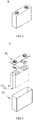
- FIG. 4 is a three-dimensional view of an implementation of a lithium-ion battery 5.
- FIG. 5 is an exploded view of FIG. 4 .
- the lithium-ion battery 5 includes a casing 51, an electrode assembly 52, and a top cover assembly 53.
- the electrode assembly 52 is accommodated in the casing 51.
- the electrode assembly 52 includes a positive-electrode plate 521, a negative-electrode plate, and a separator.
- the separator separates the positive-electrode plate 521 from the negative-electrode plate.
- the electrolyte is injected into the casing 51 and soaks the electrode assembly 51, and specifically soaks the positive-electrode plate 521, the negative electrode plate, and the separator.
- the quantity of electrode assemblies 52 is not limited, and may be one or more.
- the battery shown in FIG. 4 is a can-shaped battery, but the battery in this application is not limited to a can-shaped battery.
- the lithium-ion battery 5 may be a pouch-shaped battery. That is, the casing 51 is replaced with a metal laminated film, and the top cover assembly 53 is removed.
- the negative-electrode plate includes a negative-electrode current collector and a negative-electrode active substance layer.
- the negative-electrode active substance layer may be disposed on one surface of the negative-electrode current collector, or may be disposed on two surfaces of the negative-electrode current collector.
- the negative-electrode active substance may be one or more of metal lithium, a carbon-based negative-electrode material, a silicon-based material, a tin-based material, or lithium titanate.
- the carbon-based negative-electrode material may be one or more of natural graphite, artificial graphite, mesocarbon microbead (MCMB), hard carbon, soft-carbon nanocarbon, or carbon fiber.
- the silicon-based material may be one or more of silicon, a silicon-carbon composite, or a silicon-oxygen compound.
- the tin-based material may be one or more of elemental tin, a tin-oxygen compound, a tin-carbon composite, or a tin alloy.
- a second inorganic layer containing no binder is disposed on the surface of the negative-electrode plate, and a resistance of the negative-electrode plate is not higher than 3 ohms.
- the second inorganic layer has substantially the same properties as the inorganic dielectric layer disposed on the surface of the positive-electrode active substance layer.
- the negative-electrode active substance layer further includes a binder and a conductive agent.
- the binder may be specifically one or more of styrene-butadiene rubber (SBR) or sodium carboxymethyl cellulose (CMC).
- the conductive agent may be one or more of conductive carbon black, superconducting carbon black, conductive graphite, acetylene black, Ketjen black, graphene, or carbon nanotube.
- the specific type of the negative-electrode current collector is not limited, and may be selected according to needs.
- the negative-electrode current collector may be a copper foil.
- a specific composition of the electrolyte is not limited, and may be prepared according to actual needs.
- the electrolyte includes a lithium salt, an organic solvent, and an optional additive.
- the specific type of the organic solvent is not limited, and may be selected according to needs.
- the organic solvent may be at least two of ethylene carbonate (EC), propylene carbonate, butylene carbonate, fluoroethylene carbonate (FEC), ethyl methyl carbonate (EMC), dimethyl carbonate, diethyl carbonate (DEC), dipropyl carbonate, methyl propyl carbonate, ethyl propyl carbonate, 1,4-butyrolactone, methyl propionate, methyl butyrate, ethyl acetate, ethyl propionate, ethyl butyrate, sulfolane, dimethyl sulfone, methyl ethyl sulfone, or diethyl sulfone.
- the specific type of the lithium salt is not limited, and may be selected according to needs.
- the lithium salt may be one or more of LiPF6, LiBF4, LiClO 4 , LiAsF6, LiFSI, LiTFSI, LiTFS, LiPO 2 F 2 , LiDFOB, or LiBOB.
- a concentration of the lithium salt is 0.5 mol/L to 1.5 mol/L; and further preferably, the concentration of the lithium salt is 0.8 mol/L to 1.2 mol/L.
- the electrolyte may further include one or more of vinylene carbonate (VC), vinyl ethylene carbonate (VEC), FEC, succinonitrile (SN), adiponitrile (ADN), 1,3-propene sultone (PST), tris(trimethylsilane) phosphate (TMSP), or tris(trimethylsilane) borate (TMSB).
- VC vinylene carbonate
- VEC vinyl ethylene carbonate
- FEC FEC
- ADN succinonitrile
- ADN 1,3-propene sultone
- PST 1,3-propene sultone
- TMSP tris(trimethylsilane) phosphate
- TMSB tris(trimethylsilane) borate
- the electrolyte may be prepared using conventional methods, for example, by homogeneously mixing materials in the electrolyte.
- materials in the electrolyte for example, lithium salt, an additive A, and an additive B are added to an organic solvent and mixed to obtain the electrolyte.
- Specific order of adding the materials is not limited.
- the lithium salt may be added into the organic solvent first, and then the additive A and the additive B are simultaneously added into the organic solvent and homogeneously mixed to obtain the electrolyte.
- the specific type of the separator is not limited, and may be selected according to needs.
- the separator may be, but not limited to, polyethylene, polypropylene, or polyvinylidene fluoride, or a multilayer composite film of the polyethylene, the polypropylene, or the polyvinylidene fluoride.
- the separator may be a bare film made from such materials, or may be a product obtained by coating the bare film.
- the coating differs depending on use conditions of the separator.
- the coating may be a ceramic coating or an organic coating.
- a third aspect of this application discloses a battery module, including the lithium-ion battery disclosed in the second aspect of this application.
- FIG. 6 is a three-dimensional view of an implementation of a battery module 4.
- the battery module 4 includes a plurality of lithium-ion batteries 5.
- the plurality of batteries 5 are arranged in the longitudinal direction.
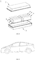
- FIG. 7 is a three-dimensional view of an implementation of a battery pack 1.
- FIG. 8 is an exploded view of FIG. 7 .
- the battery pack 1 includes an upper container part 2, a lower container part 3, and a battery module 4.
- the upper container part 2 and the lower container part 3 are assembled together to form a space for accommodating the battery module 4.
- the battery module 4 is fitted into a space formed by assembling the upper container part 2 and the lower container part 3 together.
- An output electrode of the battery module 4 passes through one of the upper container part 2 or the lower container part 3 or is led out between the upper container part 2 and the lower container part 3, to supply power to the outside or to be charged from the outside.
- the quantity and arrangement of battery modules 4 may be determined according to actual needs.
- this application provides an apparatus, including the lithium-ion battery disclosed in the second aspect of this application, or the battery module disclosed in the third aspect, or the battery pack disclosed in the fourth aspect.
- the lithium-ion battery may be used as a power supply of the apparatus.
- the apparatus includes a pure electric vehicle, a hybrid electric vehicle, a plug-in hybrid electric vehicle, an electric bicycle, an electric scooter, an electric golf cart, an electric truck, and an energy storage system.
- FIG. 9 is a schematic diagram of an implementation of an apparatus using a lithium-ion battery as a power supply.
- the battery module, the battery pack, and the apparatus include the lithium-ion battery disclosed in this application, and therefore, have at least the same advantages as the lithium-ion battery, details of which are omitted here.
- the lithium-ion batteries in Examples 1 to 15 were all manufactured according to the following methods.
- Example 2 was repeated, except that: no inorganic dielectric layer was disposed on the surface of the positive-electrode plate.
- Example 2 was repeated, except that the thickness of the inorganic dielectric layer on the surface of the positive-electrode plate was 1200 nm.
- Example 2 was repeated, except that the inorganic dielectric layer disposed on the surface of the positive-electrode plate was obtained by coating the positive-electrode plate with a slurry comprising a binder and alumina ceramic particles, followed by cold calendering and drying.
- Example 1 27.30% 79.40% 21.60% 90.90% 24.10%
- Example 2 25.40% 85.90% 21.40% 85.70% 21.00%
- Example 3 24.30% 86.60% 19.40% 84.70% 23.30%
- Example 4 22.10% 87.70% 23.70% 87.70% 21.40%
- Example 5 21.00% 84.20% 20.80% 84.90% 23.20%
- Example 6 20.70% 82.90% 24.50% 79.10% 26.10%
- Example 7 21.10% 79.00% 25.50% 79.50% 25.10%
- Example 8 20.80% 78.10% 28.10% 78.40% 24.10%
- Example 9 23.10% 88.80% 22.60% 83.40% 21.30%
- Example 10 22.50% 85.70%
- the inorganic dielectric layer also served as an insulating interface between the positive-electrode plate and the separator, and prevented a separator polymer from oxidation and failure due to contact with the highly oxidative positive-electrode plate under a high voltage.
- Comparative Example 1 no inorganic dielectric layer was disposed on the surface of the positive-electrode active substance layer.
- the surface of the positive-electrode plate was highly oxidative, and many side reactions of the electrolyte occurred on the surface of the electrode plate. Consequently, the volume expansion rate of the battery was relatively high, an internal impedance of the battery increased significantly, and the capacity retention rate decreased drastically.
Landscapes
- Chemical & Material Sciences (AREA)
- Chemical Kinetics & Catalysis (AREA)
- Electrochemistry (AREA)
- General Chemical & Material Sciences (AREA)
- Engineering & Computer Science (AREA)
- Inorganic Chemistry (AREA)
- Materials Engineering (AREA)
- Composite Materials (AREA)
- Manufacturing & Machinery (AREA)
- Organic Chemistry (AREA)
- Secondary Cells (AREA)
- Battery Electrode And Active Subsutance (AREA)
Applications Claiming Priority (2)
| Application Number | Priority Date | Filing Date | Title |
|---|---|---|---|
| CN201811151916.1A CN110970613B (zh) | 2018-09-29 | 2018-09-29 | 一种正极极片以及使用该正极极片的锂离子电池 |
| PCT/CN2019/108134 WO2020063740A1 (zh) | 2018-09-29 | 2019-09-26 | 一种正极极片、使用该正极极片的锂离子电池、电池模块、电池包及装置 |
Publications (3)
| Publication Number | Publication Date |
|---|---|
| EP3787068A1 true EP3787068A1 (de) | 2021-03-03 |
| EP3787068A4 EP3787068A4 (de) | 2021-08-11 |
| EP3787068B1 EP3787068B1 (de) | 2022-10-19 |
Family
ID=69950995
Family Applications (1)
| Application Number | Title | Priority Date | Filing Date |
|---|---|---|---|
| EP19866720.6A Active EP3787068B1 (de) | 2018-09-29 | 2019-09-26 | Positives polstück und lithiumionenbatterie, batteriemodul, batteriepack und vorrichtung mit positivem polstück |
Country Status (4)
| Country | Link |
|---|---|
| US (1) | US12074315B2 (de) |
| EP (1) | EP3787068B1 (de) |
| CN (1) | CN110970613B (de) |
| WO (1) | WO2020063740A1 (de) |
Cited By (1)
| Publication number | Priority date | Publication date | Assignee | Title |
|---|---|---|---|---|
| EP4131507A4 (de) * | 2021-04-12 | 2025-07-09 | Shenzhen Dynanonic Innovazone New Energy Tech Co Ltd | Lithiumzusatzadditiv, herstellungsverfahren dafür und anwendung davon |
Families Citing this family (10)
| Publication number | Priority date | Publication date | Assignee | Title |
|---|---|---|---|---|
| CN112467121A (zh) * | 2020-12-03 | 2021-03-09 | 珠海冠宇电池股份有限公司 | 一种正极片及其制备方法和应用 |
| WO2022267013A1 (zh) * | 2021-06-25 | 2022-12-29 | 宁德新能源科技有限公司 | 电化学装置及电子装置 |
| CN113793930B (zh) * | 2021-09-17 | 2023-04-25 | 珠海冠宇电池股份有限公司 | 一种正极片及锂离子电池 |
| CN115979907B (zh) * | 2021-10-14 | 2024-11-19 | 比亚迪股份有限公司 | 一种电极片的孔隙检测方法及电极片 |
| CN114477300B (zh) * | 2022-01-26 | 2023-12-22 | 蜂巢能源科技股份有限公司 | 一种钠离子电池正极材料及其制备方法和应用 |
| CN114583104B (zh) * | 2022-02-24 | 2023-11-28 | 珠海冠宇动力电池有限公司 | 一种正极片和电池 |
| CN114864886B (zh) * | 2022-04-02 | 2024-02-27 | 万华化学集团股份有限公司 | 一种正极材料及其制备方法 |
| CN115799441B (zh) * | 2023-02-10 | 2023-07-14 | 欣旺达电动汽车电池有限公司 | 一种锂离子电池及用电装置 |
| CN118738261A (zh) * | 2023-03-28 | 2024-10-01 | 宁德时代新能源科技股份有限公司 | 正极极片及其制备方法、电极组件、电池单体、电池和用电装置 |
| CN117497766A (zh) * | 2024-01-03 | 2024-02-02 | 宁德时代新能源科技股份有限公司 | 负极极片及其制备方法、电池和用电装置 |
Family Cites Families (16)
| Publication number | Priority date | Publication date | Assignee | Title |
|---|---|---|---|---|
| JP5374851B2 (ja) * | 2007-10-15 | 2013-12-25 | ソニー株式会社 | リチウムイオン二次電池用負極およびリチウムイオン二次電池 |
| JP5271275B2 (ja) * | 2007-12-14 | 2013-08-21 | パナソニック株式会社 | 非水電解質二次電池の製造方法 |
| JP4563503B2 (ja) * | 2007-12-26 | 2010-10-13 | パナソニック株式会社 | 非水電解質二次電池 |
| US9196901B2 (en) * | 2010-06-14 | 2015-11-24 | Lee Se-Hee | Lithium battery electrodes with ultra-thin alumina coatings |
| US8980472B2 (en) | 2010-08-05 | 2015-03-17 | Toyota Jidosha Kabushiki Kaisha | Secondary battery |
| CN102420300A (zh) * | 2011-12-07 | 2012-04-18 | 保定市山河日月实业有限公司 | 一种锂离子电池隔膜的制备方法 |
| CN103682247B (zh) * | 2012-09-24 | 2017-02-08 | 华为技术有限公司 | 一种锂离子电池用复合负极片及其制备方法和锂离子电池 |
| CN103413966B (zh) * | 2013-07-18 | 2015-08-05 | 中国科学院金属研究所 | 一种具有膜电极结构的锂离子电池及其制备方法 |
| CN104064705B (zh) * | 2014-06-09 | 2017-01-04 | 东莞市魔方新能源科技有限公司 | 一种锂离子二次电池用复合隔膜、其制造方法及含该隔膜的电化学装置 |
| JP6252524B2 (ja) * | 2015-03-12 | 2017-12-27 | トヨタ自動車株式会社 | 固体電池用正極活物質の製造方法 |
| KR102072220B1 (ko) * | 2016-01-12 | 2020-01-31 | 주식회사 엘지화학 | 디바이스에 대한 탑재 공간이 최소화된 전지팩 |
| CN106229447A (zh) * | 2016-08-10 | 2016-12-14 | 东莞永蓝电子科技有限公司 | 一种锂离子电池 |
| CN107749457B (zh) * | 2016-11-18 | 2020-07-31 | 万向一二三股份公司 | 一种含正极陶瓷涂层的锂离子电池 |
| CN115632104A (zh) * | 2017-12-20 | 2023-01-20 | 宁德时代新能源科技股份有限公司 | 一种负极极片,其制备方法及电化学装置 |
| CN109994705B (zh) | 2017-12-29 | 2022-01-14 | 宁德时代新能源科技股份有限公司 | 一种正极极片,其制备方法及电化学装置 |
| CN108807974B (zh) * | 2018-06-29 | 2021-07-09 | 宁德时代新能源科技股份有限公司 | 锂离子电池 |
-
2018
- 2018-09-29 CN CN201811151916.1A patent/CN110970613B/zh active Active
-
2019
- 2019-09-26 EP EP19866720.6A patent/EP3787068B1/de active Active
- 2019-09-26 US US17/057,062 patent/US12074315B2/en active Active
- 2019-09-26 WO PCT/CN2019/108134 patent/WO2020063740A1/zh not_active Ceased
Cited By (1)
| Publication number | Priority date | Publication date | Assignee | Title |
|---|---|---|---|---|
| EP4131507A4 (de) * | 2021-04-12 | 2025-07-09 | Shenzhen Dynanonic Innovazone New Energy Tech Co Ltd | Lithiumzusatzadditiv, herstellungsverfahren dafür und anwendung davon |
Also Published As
| Publication number | Publication date |
|---|---|
| CN110970613A (zh) | 2020-04-07 |
| EP3787068B1 (de) | 2022-10-19 |
| US12074315B2 (en) | 2024-08-27 |
| EP3787068A4 (de) | 2021-08-11 |
| CN110970613B (zh) | 2021-06-15 |
| WO2020063740A1 (zh) | 2020-04-02 |
| US20210210749A1 (en) | 2021-07-08 |
Similar Documents
| Publication | Publication Date | Title |
|---|---|---|
| EP3787068B1 (de) | Positives polstück und lithiumionenbatterie, batteriemodul, batteriepack und vorrichtung mit positivem polstück | |
| EP4123759B1 (de) | Negativelektrodenplatte und lithium-ionen-sekundärbatterie | |
| CN102088109B (zh) | 非水电解质二次电池和隔膜 | |
| CN110720156B (zh) | 锂离子二次电池 | |
| JP6070540B2 (ja) | 二次電池および電解液 | |
| EP2840640B1 (de) | Lithiumsekundärbatterie | |
| CN108292779B (zh) | 锂离子二次电池 | |
| EP2822083B1 (de) | Lithiumsekundärbatterie mit verbesserten frequenzeigenschaften | |
| CN118899512A (zh) | 二次电池与含有该二次电池的电池模块、电池包和用电装置 | |
| JP2011096638A (ja) | 二次電池 | |
| KR102793639B1 (ko) | 포스파이트계 첨가제 및 설포네이트계 첨가제를 포함하는 전해질 및 이를 포함하는 리튬이차전지 | |
| JP6052168B2 (ja) | リチウム二次電池 | |
| US10923770B2 (en) | Lithium ion secondary battery | |
| EP4195348A1 (de) | Elektrochemische vorrichtung und stromverbrauchende vorrichtung mit der elektrochemischen vorrichtung | |
| CN117121257A (zh) | 锂二次电池用非水性电解质溶液及包含其的锂二次电池 | |
| EP4040561A1 (de) | Elektrolyt für lithiummetallsekundärbatterie | |
| JPWO2015015883A1 (ja) | リチウム二次電池及びリチウム二次電池用電解液 | |
| JP2026062909A (ja) | 非水電解液及びそれを含む二次電池、電池モジュール、電池パック及び電力消費装置 | |
| JP5793411B2 (ja) | リチウム二次電池 | |
| JP2022046160A (ja) | リチウムイオン二次電池およびその製造方法 | |
| WO2014171518A2 (ja) | リチウムイオン二次電池 | |
| JP2012033346A (ja) | 非プロトン性電解液二次電池 | |
| US8318347B2 (en) | Lithium ion secondary battery | |
| KR102619182B1 (ko) | 리튬 이차전지용 비수전해액 및 이를 포함하는 리튬 이차전지 | |
| JPWO2012029645A1 (ja) | 二次電池およびそれに用いる二次電池用電解液 |
Legal Events
| Date | Code | Title | Description |
|---|---|---|---|
| STAA | Information on the status of an ep patent application or granted ep patent |
Free format text: STATUS: THE INTERNATIONAL PUBLICATION HAS BEEN MADE |
|
| PUAI | Public reference made under article 153(3) epc to a published international application that has entered the european phase |
Free format text: ORIGINAL CODE: 0009012 |
|
| STAA | Information on the status of an ep patent application or granted ep patent |
Free format text: STATUS: REQUEST FOR EXAMINATION WAS MADE |
|
| 17P | Request for examination filed |
Effective date: 20201125 |
|
| AK | Designated contracting states |
Kind code of ref document: A1 Designated state(s): AL AT BE BG CH CY CZ DE DK EE ES FI FR GB GR HR HU IE IS IT LI LT LU LV MC MK MT NL NO PL PT RO RS SE SI SK SM TR |
|
| AX | Request for extension of the european patent |
Extension state: BA ME |
|
| A4 | Supplementary search report drawn up and despatched |
Effective date: 20210709 |
|
| RIC1 | Information provided on ipc code assigned before grant |
Ipc: H01M 4/13 20100101AFI20210705BHEP Ipc: H01M 4/36 20060101ALI20210705BHEP Ipc: H01M 4/62 20060101ALI20210705BHEP Ipc: H01M 10/42 20060101ALI20210705BHEP Ipc: H01M 10/0525 20100101ALI20210705BHEP Ipc: H01M 4/02 20060101ALI20210705BHEP Ipc: H01M 4/131 20100101ALI20210705BHEP Ipc: H01M 4/525 20100101ALI20210705BHEP |
|
| DAV | Request for validation of the european patent (deleted) | ||
| DAX | Request for extension of the european patent (deleted) | ||
| STAA | Information on the status of an ep patent application or granted ep patent |
Free format text: STATUS: EXAMINATION IS IN PROGRESS |
|
| 17Q | First examination report despatched |
Effective date: 20220215 |
|
| GRAP | Despatch of communication of intention to grant a patent |
Free format text: ORIGINAL CODE: EPIDOSNIGR1 |
|
| STAA | Information on the status of an ep patent application or granted ep patent |
Free format text: STATUS: GRANT OF PATENT IS INTENDED |
|
| INTG | Intention to grant announced |
Effective date: 20220801 |
|
| GRAS | Grant fee paid |
Free format text: ORIGINAL CODE: EPIDOSNIGR3 |
|
| GRAA | (expected) grant |
Free format text: ORIGINAL CODE: 0009210 |
|
| STAA | Information on the status of an ep patent application or granted ep patent |
Free format text: STATUS: THE PATENT HAS BEEN GRANTED |
|
| RAP3 | Party data changed (applicant data changed or rights of an application transferred) |
Owner name: CONTEMPORARY AMPEREX TECHNOLOGY CO., LIMITED |
|
| AK | Designated contracting states |
Kind code of ref document: B1 Designated state(s): AL AT BE BG CH CY CZ DE DK EE ES FI FR GB GR HR HU IE IS IT LI LT LU LV MC MK MT NL NO PL PT RO RS SE SI SK SM TR |
|
| REG | Reference to a national code |
Ref country code: GB Ref legal event code: FG4D |
|
| REG | Reference to a national code |
Ref country code: CH Ref legal event code: EP |
|
| REG | Reference to a national code |
Ref country code: IE Ref legal event code: FG4D |
|
| REG | Reference to a national code |
Ref country code: DE Ref legal event code: R096 Ref document number: 602019020932 Country of ref document: DE |
|
| REG | Reference to a national code |
Ref country code: SE Ref legal event code: TRGR Ref country code: AT Ref legal event code: REF Ref document number: 1526121 Country of ref document: AT Kind code of ref document: T Effective date: 20221115 |
|
| REG | Reference to a national code |
Ref country code: LT Ref legal event code: MG9D |
|
| REG | Reference to a national code |
Ref country code: NL Ref legal event code: MP Effective date: 20221019 |
|
| REG | Reference to a national code |
Ref country code: AT Ref legal event code: MK05 Ref document number: 1526121 Country of ref document: AT Kind code of ref document: T Effective date: 20221019 |
|
| PG25 | Lapsed in a contracting state [announced via postgrant information from national office to epo] |
Ref country code: NL Free format text: LAPSE BECAUSE OF FAILURE TO SUBMIT A TRANSLATION OF THE DESCRIPTION OR TO PAY THE FEE WITHIN THE PRESCRIBED TIME-LIMIT Effective date: 20221019 |
|
| PG25 | Lapsed in a contracting state [announced via postgrant information from national office to epo] |
Ref country code: PT Free format text: LAPSE BECAUSE OF FAILURE TO SUBMIT A TRANSLATION OF THE DESCRIPTION OR TO PAY THE FEE WITHIN THE PRESCRIBED TIME-LIMIT Effective date: 20230220 Ref country code: NO Free format text: LAPSE BECAUSE OF FAILURE TO SUBMIT A TRANSLATION OF THE DESCRIPTION OR TO PAY THE FEE WITHIN THE PRESCRIBED TIME-LIMIT Effective date: 20230119 Ref country code: LT Free format text: LAPSE BECAUSE OF FAILURE TO SUBMIT A TRANSLATION OF THE DESCRIPTION OR TO PAY THE FEE WITHIN THE PRESCRIBED TIME-LIMIT Effective date: 20221019 Ref country code: FI Free format text: LAPSE BECAUSE OF FAILURE TO SUBMIT A TRANSLATION OF THE DESCRIPTION OR TO PAY THE FEE WITHIN THE PRESCRIBED TIME-LIMIT Effective date: 20221019 Ref country code: ES Free format text: LAPSE BECAUSE OF FAILURE TO SUBMIT A TRANSLATION OF THE DESCRIPTION OR TO PAY THE FEE WITHIN THE PRESCRIBED TIME-LIMIT Effective date: 20221019 Ref country code: AT Free format text: LAPSE BECAUSE OF FAILURE TO SUBMIT A TRANSLATION OF THE DESCRIPTION OR TO PAY THE FEE WITHIN THE PRESCRIBED TIME-LIMIT Effective date: 20221019 |
|
| PG25 | Lapsed in a contracting state [announced via postgrant information from national office to epo] |
Ref country code: RS Free format text: LAPSE BECAUSE OF FAILURE TO SUBMIT A TRANSLATION OF THE DESCRIPTION OR TO PAY THE FEE WITHIN THE PRESCRIBED TIME-LIMIT Effective date: 20221019 Ref country code: PL Free format text: LAPSE BECAUSE OF FAILURE TO SUBMIT A TRANSLATION OF THE DESCRIPTION OR TO PAY THE FEE WITHIN THE PRESCRIBED TIME-LIMIT Effective date: 20221019 Ref country code: LV Free format text: LAPSE BECAUSE OF FAILURE TO SUBMIT A TRANSLATION OF THE DESCRIPTION OR TO PAY THE FEE WITHIN THE PRESCRIBED TIME-LIMIT Effective date: 20221019 Ref country code: IS Free format text: LAPSE BECAUSE OF FAILURE TO SUBMIT A TRANSLATION OF THE DESCRIPTION OR TO PAY THE FEE WITHIN THE PRESCRIBED TIME-LIMIT Effective date: 20230219 Ref country code: HR Free format text: LAPSE BECAUSE OF FAILURE TO SUBMIT A TRANSLATION OF THE DESCRIPTION OR TO PAY THE FEE WITHIN THE PRESCRIBED TIME-LIMIT Effective date: 20221019 Ref country code: GR Free format text: LAPSE BECAUSE OF FAILURE TO SUBMIT A TRANSLATION OF THE DESCRIPTION OR TO PAY THE FEE WITHIN THE PRESCRIBED TIME-LIMIT Effective date: 20230120 |
|
| P01 | Opt-out of the competence of the unified patent court (upc) registered |
Effective date: 20230516 |
|
| REG | Reference to a national code |
Ref country code: DE Ref legal event code: R097 Ref document number: 602019020932 Country of ref document: DE |
|
| PG25 | Lapsed in a contracting state [announced via postgrant information from national office to epo] |
Ref country code: SM Free format text: LAPSE BECAUSE OF FAILURE TO SUBMIT A TRANSLATION OF THE DESCRIPTION OR TO PAY THE FEE WITHIN THE PRESCRIBED TIME-LIMIT Effective date: 20221019 Ref country code: RO Free format text: LAPSE BECAUSE OF FAILURE TO SUBMIT A TRANSLATION OF THE DESCRIPTION OR TO PAY THE FEE WITHIN THE PRESCRIBED TIME-LIMIT Effective date: 20221019 Ref country code: EE Free format text: LAPSE BECAUSE OF FAILURE TO SUBMIT A TRANSLATION OF THE DESCRIPTION OR TO PAY THE FEE WITHIN THE PRESCRIBED TIME-LIMIT Effective date: 20221019 Ref country code: DK Free format text: LAPSE BECAUSE OF FAILURE TO SUBMIT A TRANSLATION OF THE DESCRIPTION OR TO PAY THE FEE WITHIN THE PRESCRIBED TIME-LIMIT Effective date: 20221019 Ref country code: CZ Free format text: LAPSE BECAUSE OF FAILURE TO SUBMIT A TRANSLATION OF THE DESCRIPTION OR TO PAY THE FEE WITHIN THE PRESCRIBED TIME-LIMIT Effective date: 20221019 |
|
| PLBE | No opposition filed within time limit |
Free format text: ORIGINAL CODE: 0009261 |
|
| STAA | Information on the status of an ep patent application or granted ep patent |
Free format text: STATUS: NO OPPOSITION FILED WITHIN TIME LIMIT |
|
| PG25 | Lapsed in a contracting state [announced via postgrant information from national office to epo] |
Ref country code: SK Free format text: LAPSE BECAUSE OF FAILURE TO SUBMIT A TRANSLATION OF THE DESCRIPTION OR TO PAY THE FEE WITHIN THE PRESCRIBED TIME-LIMIT Effective date: 20221019 Ref country code: AL Free format text: LAPSE BECAUSE OF FAILURE TO SUBMIT A TRANSLATION OF THE DESCRIPTION OR TO PAY THE FEE WITHIN THE PRESCRIBED TIME-LIMIT Effective date: 20221019 |
|
| 26N | No opposition filed |
Effective date: 20230720 |
|
| PG25 | Lapsed in a contracting state [announced via postgrant information from national office to epo] |
Ref country code: SI Free format text: LAPSE BECAUSE OF FAILURE TO SUBMIT A TRANSLATION OF THE DESCRIPTION OR TO PAY THE FEE WITHIN THE PRESCRIBED TIME-LIMIT Effective date: 20221019 |
|
| REG | Reference to a national code |
Ref country code: CH Ref legal event code: PL |
|
| PG25 | Lapsed in a contracting state [announced via postgrant information from national office to epo] |
Ref country code: LU Free format text: LAPSE BECAUSE OF NON-PAYMENT OF DUE FEES Effective date: 20230926 |
|
| REG | Reference to a national code |
Ref country code: BE Ref legal event code: MM Effective date: 20230930 |
|
| PG25 | Lapsed in a contracting state [announced via postgrant information from national office to epo] |
Ref country code: LU Free format text: LAPSE BECAUSE OF NON-PAYMENT OF DUE FEES Effective date: 20230926 Ref country code: IT Free format text: LAPSE BECAUSE OF FAILURE TO SUBMIT A TRANSLATION OF THE DESCRIPTION OR TO PAY THE FEE WITHIN THE PRESCRIBED TIME-LIMIT Effective date: 20221019 Ref country code: MC Free format text: LAPSE BECAUSE OF FAILURE TO SUBMIT A TRANSLATION OF THE DESCRIPTION OR TO PAY THE FEE WITHIN THE PRESCRIBED TIME-LIMIT Effective date: 20221019 |
|
| REG | Reference to a national code |
Ref country code: IE Ref legal event code: MM4A |
|
| PG25 | Lapsed in a contracting state [announced via postgrant information from national office to epo] |
Ref country code: IE Free format text: LAPSE BECAUSE OF NON-PAYMENT OF DUE FEES Effective date: 20230926 |
|
| PG25 | Lapsed in a contracting state [announced via postgrant information from national office to epo] |
Ref country code: CH Free format text: LAPSE BECAUSE OF NON-PAYMENT OF DUE FEES Effective date: 20230930 |
|
| PG25 | Lapsed in a contracting state [announced via postgrant information from national office to epo] |
Ref country code: IE Free format text: LAPSE BECAUSE OF NON-PAYMENT OF DUE FEES Effective date: 20230926 Ref country code: CH Free format text: LAPSE BECAUSE OF NON-PAYMENT OF DUE FEES Effective date: 20230930 |
|
| REG | Reference to a national code |
Ref country code: DE Ref legal event code: R081 Ref document number: 602019020932 Country of ref document: DE Owner name: CONTEMPORARY AMPEREX TECHNOLOGY (HONG KONG) LI, HK Free format text: FORMER OWNER: CONTEMPORARY AMPEREX TECHNOLOGY CO., LIMITED, NINGDE CITY, FUJIAN, CN |
|
| PG25 | Lapsed in a contracting state [announced via postgrant information from national office to epo] |
Ref country code: BE Free format text: LAPSE BECAUSE OF NON-PAYMENT OF DUE FEES Effective date: 20230930 |
|
| REG | Reference to a national code |
Ref country code: GB Ref legal event code: 732E Free format text: REGISTERED BETWEEN 20240829 AND 20240904 |
|
| PG25 | Lapsed in a contracting state [announced via postgrant information from national office to epo] |
Ref country code: BG Free format text: LAPSE BECAUSE OF FAILURE TO SUBMIT A TRANSLATION OF THE DESCRIPTION OR TO PAY THE FEE WITHIN THE PRESCRIBED TIME-LIMIT Effective date: 20221019 |
|
| PG25 | Lapsed in a contracting state [announced via postgrant information from national office to epo] |
Ref country code: BG Free format text: LAPSE BECAUSE OF FAILURE TO SUBMIT A TRANSLATION OF THE DESCRIPTION OR TO PAY THE FEE WITHIN THE PRESCRIBED TIME-LIMIT Effective date: 20221019 |
|
| PG25 | Lapsed in a contracting state [announced via postgrant information from national office to epo] |
Ref country code: CY Free format text: LAPSE BECAUSE OF FAILURE TO SUBMIT A TRANSLATION OF THE DESCRIPTION OR TO PAY THE FEE WITHIN THE PRESCRIBED TIME-LIMIT; INVALID AB INITIO Effective date: 20190926 |
|
| PG25 | Lapsed in a contracting state [announced via postgrant information from national office to epo] |
Ref country code: HU Free format text: LAPSE BECAUSE OF FAILURE TO SUBMIT A TRANSLATION OF THE DESCRIPTION OR TO PAY THE FEE WITHIN THE PRESCRIBED TIME-LIMIT; INVALID AB INITIO Effective date: 20190926 |
|
| PGFP | Annual fee paid to national office [announced via postgrant information from national office to epo] |
Ref country code: DE Payment date: 20250702 Year of fee payment: 7 |
|
| PGFP | Annual fee paid to national office [announced via postgrant information from national office to epo] |
Ref country code: GB Payment date: 20250703 Year of fee payment: 7 |
|
| PGFP | Annual fee paid to national office [announced via postgrant information from national office to epo] |
Ref country code: FR Payment date: 20250808 Year of fee payment: 7 |
|
| PGFP | Annual fee paid to national office [announced via postgrant information from national office to epo] |
Ref country code: SE Payment date: 20250922 Year of fee payment: 7 |
|
| PG25 | Lapsed in a contracting state [announced via postgrant information from national office to epo] |
Ref country code: TR Free format text: LAPSE BECAUSE OF FAILURE TO SUBMIT A TRANSLATION OF THE DESCRIPTION OR TO PAY THE FEE WITHIN THE PRESCRIBED TIME-LIMIT Effective date: 20221019 |