EP3787205A1 - Optische übertragungsvorrichtung, optische empfangsvorrichtung, optisches kommunikationssystem, optisches übertragungsverfahren, einstellverfahren und computerlesbares medium - Google Patents
Optische übertragungsvorrichtung, optische empfangsvorrichtung, optisches kommunikationssystem, optisches übertragungsverfahren, einstellverfahren und computerlesbares medium Download PDFInfo
- Publication number
- EP3787205A1 EP3787205A1 EP19793040.7A EP19793040A EP3787205A1 EP 3787205 A1 EP3787205 A1 EP 3787205A1 EP 19793040 A EP19793040 A EP 19793040A EP 3787205 A1 EP3787205 A1 EP 3787205A1
- Authority
- EP
- European Patent Office
- Prior art keywords
- transmission
- filtering processing
- band
- reception
- optical
- Prior art date
- Legal status (The legal status is an assumption and is not a legal conclusion. Google has not performed a legal analysis and makes no representation as to the accuracy of the status listed.)
- Withdrawn
Links
Images







Classifications
-
- H—ELECTRICITY
- H04—ELECTRIC COMMUNICATION TECHNIQUE
- H04J—MULTIPLEX COMMUNICATION
- H04J14/00—Optical multiplex systems
- H04J14/02—Wavelength-division multiplex systems
- H04J14/0201—Add-and-drop multiplexing
- H04J14/0202—Arrangements therefor
- H04J14/0209—Multi-stage arrangements, e.g. by cascading multiplexers or demultiplexers
-
- H—ELECTRICITY
- H04—ELECTRIC COMMUNICATION TECHNIQUE
- H04B—TRANSMISSION
- H04B10/00—Transmission systems employing electromagnetic waves other than radio-waves, e.g. infrared, visible or ultraviolet light, or employing corpuscular radiation, e.g. quantum communication
- H04B10/60—Receivers
- H04B10/66—Non-coherent receivers, e.g. using direct detection
- H04B10/67—Optical arrangements in the receiver
-
- H—ELECTRICITY
- H04—ELECTRIC COMMUNICATION TECHNIQUE
- H04B—TRANSMISSION
- H04B10/00—Transmission systems employing electromagnetic waves other than radio-waves, e.g. infrared, visible or ultraviolet light, or employing corpuscular radiation, e.g. quantum communication
- H04B10/50—Transmitters
- H04B10/501—Structural aspects
- H04B10/506—Multiwavelength transmitters
-
- H—ELECTRICITY
- H04—ELECTRIC COMMUNICATION TECHNIQUE
- H04B—TRANSMISSION
- H04B10/00—Transmission systems employing electromagnetic waves other than radio-waves, e.g. infrared, visible or ultraviolet light, or employing corpuscular radiation, e.g. quantum communication
- H04B10/50—Transmitters
- H04B10/572—Wavelength control
-
- H—ELECTRICITY
- H04—ELECTRIC COMMUNICATION TECHNIQUE
- H04J—MULTIPLEX COMMUNICATION
- H04J14/00—Optical multiplex systems
- H04J14/02—Wavelength-division multiplex systems
- H04J14/0227—Operation, administration, maintenance or provisioning [OAMP] of WDM networks, e.g. media access, routing or wavelength allocation
- H04J14/0254—Optical medium access
- H04J14/0256—Optical medium access at the optical channel layer
Definitions
- the present invention relates to an optical communication system configured to transmit and receive optical signals through a transmission line.
- a multiplexing-demultiplexing device for transmitting a wavelength multiplexed optical signal including a plurality of optical signals is provided in an optical transmission device provided at a terminal station.
- a wavelength selective switch WSS is used as the multiplexing-demultiplexing device (see PTL 1).
- the WSS includes a plurality of ports to which optical signals are input, and a wavelength band for filtering an input optical signal is set to each port.
- the WSS filters each input optical signal and converts the optical signal into an optical signal in a predetermined frequency band, and then multiplexes the optical signals and outputs the multiplexed optical signal after multiplexing to a transmission line.
- a WSS filters each input optical signal in a wavelength band roughly identical to a wavelength band of the optical signal.
- narrowing of an optical spectrum due to a filter characteristic of the WSS occurs in an optical signal filtered through the roughly identical wavelength band.
- WSSs are provided in a plurality of stages in the aforementioned optical transmission device. At this time, it is conceivable that edges of a filter in a first-stage WSS and a filter in a next-stage WSS overlap or become close to each other. In that case, a signal band of an optical signal transmitted through the filters may be excessively narrowed. This may affect transmission quality.
- An object of the present invention is to provide an optical transmission device that may suppress narrowing of an optical signal band occurring when multiplexing-demultiplexing devices are provided in a plurality of stages.
- An optical transmission device includes: a first multiplexing device configured to output a first wavelength multiplexed signal acquired by multiplexing each of one or more first processed signals acquired by performing first filtering processing on each of one or more input transmission optical signals; and a second multiplexing device configured to output a second wavelength multiplexed signal acquired by multiplexing each of one or more of the first wavelength multiplexed signals undergoing second filtering processing, wherein an upper limit and a lower limit of each of one or more first transmission bands being a transmission band related to each operation of the first filtering processing are respectively different from an upper limit and a lower limit of each of one or more second transmission bands being a transmission band related to each operation of the second filtering processing.
- a transfer control device may suppress narrowing of an optical signal band occurring when multiplexing-demultiplexing devices are provided in a plurality of stages.
- a first example embodiment is an example embodiment related to an optical transmission device including a multistage multiplexing device. Configuration and Operation
- Fig. 1 is a conceptual diagram illustrating a configuration of an optical transmission device 100a being an example of the optical transmission device according to the first example embodiment.
- the optical transmission device 100a includes multiplexing devices 101a to 10na being n multiplexing devices and a multiplexing device 106a. Note that n is a number equal to or greater than 2.
- Transmission optical signals s11 to s1m are input to the multiplexing device 101a from transmitters 611 to 61m being m transmitters, respectively.
- the transmission optical signals s11 to s1m are optical signals having wavelengths different from one another. Further, the transmission optical signals s11 to s1m are optical signals in channels different from one another.
- a channel refers to a wavelength grid defined by a predetermined center frequency interval and a predetermined frequency bandwidth.
- the multiplexing device 101a is a multiplexing device in a first stage viewed from the transmitters 611 to 61m.
- the multiplexing device 101a performs, on each of the transmission optical signals s11 to s1m, transmission filtering processing [first-stage transmission filtering processing (first filtering processing)] of transmitting a set transmission band (frequency band) set to the transmission optical signal.
- the set transmission bands do not overlap one another.
- the multiplexing device 101a may be configured with a WSS.
- the multiplexing device 101a may include a plurality of ports to which the transmission optical signals s11 to s1m are input, respectively, and a transmission band may be set to each port.
- the multiplexing device 101a multiplexes the transmission optical signals after the first-stage transmission filtering processing and inputs a first-stage multiplexed transmission optical signal being a transmission optical signal after multiplexing to the multiplexing device 106a.
- the multiplexing device 106a is a multiplexing device in a next stage viewed from the transmitters 611 to 61m.
- the multiplexing device 106a performs, on each of the first-stage multiplexed transmission optical signals after multiplexing input from the multiplexing devices 101a to 10na, next-stage transmission filtering processing (second filtering processing) of transmitting the first-stage multiplexed transmission optical signal through a set set transmission band.
- the set transmission bands related to the next-stage transmission filtering processing do not overlap one another.
- the multiplexing device 106a may be configured with a WSS.
- the multiplexing device 106a may include a plurality of ports to which the first-stage multiplexed transmission optical signals after multiplexing input from the multiplexing devices 101a to 10na are input, respectively, and a transmission band may be set to each port.
- transmission refers to an amount of attenuation of a signal undergoing the filtering processing being equal to or less than a predetermined value.
- the amount of attenuation is 3 dB.
- a band in which an amount of attenuation of a signal undergoing the filtering processing is equal to or less than a predetermined value may be referred to as a transmission region, and a band in which the amount is equal to or more than the predetermined value may be referred to as a cutoff region.
- the multiplexing device 106a multiplexes the first-stage multiplexed transmission optical signals after the next-stage transmission filtering processing and outputs a next-stage multiplexed transmission optical signal after multiplexing to a transmission line 300a.
- the next-stage multiplexed transmission optical signal is transmitted to an unillustrated optical transmission device on the receiving side.
- Each of the upper limit and the lower limit of a set transmission band may be referred to as an edge.
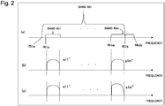
- Fig. 2 is a conceptual diagram illustrating set transmission band examples related to the transmission filtering processing performed on the transmission optical signals s11 to s1m illustrated in Fig. 1 in the multiplexing devices 101a and 106a.
- Diagram (a) in Fig. 2 illustrates set transmission bands related to the transmission filtering processing in each of the multiplexing devices 101a, 10na, and 106a illustrated in Fig. 1 .
- Diagram (b) in Fig. 2 illustrates transmission optical signals after the next-stage transmission filtering processing when each transmission band is as illustrated in Diagram (a) in Fig. 2 .
- Diagram (c) in Fig. 2 illustrates transmission optical signals after the next-stage transmission filtering processing in a case of general set transmission bands.
- a multiplexing device can set a band related to filtering processing on a per predetermined band basis.
- a band related to filtering processing is set in such a way as to include a channel of a transmitted transmission optical signal and not to include a channel of an untransmitted transmission optical signal.
- the upper limit of a band 40m being a set transmission band related to the first-stage transmission filtering processing matches the upper limit of a band 501 being a set transmission band related to the next-stage transmission filtering processing.
- Diagrams (b) and (c) in Fig. 2 illustrate optical spectra of the transmission optical signals s11 to slm.
- Each of the transmission optical signals s11 to s1m represents an optical signal of a channel in an illustrated band.
- Bands 401 to 40m illustrated in Diagram (a) in Fig. 2 are set transmission bands set to the transmission optical signals s11 to s1m in the multiplexing device 101a in this order.
- the bands 401 to 40m include bands including wavelengths included in the transmission optical signals s11 to s1m, respectively. Frequency bands included in the bands 401 to 40m become higher in this order.
- the bands 401 to 40m do not overlap one another.
- the band 501 is a set transmission band related to the next-stage transmission filtering processing performed in the multiplexing device 106a on the first-stage multiplexed transmission optical signal input from the multiplexing device 101a.
- the band 501 includes a band including the wavelengths included in the transmission optical signals s11 to s1m constituting the first-stage multiplexed transmission optical signal.
- a relation between the band 40m and the band 501 will be described.
- a frequency f4mb being the upper limit of the band 40m set by the multiplexing device 101a is positioned on the higher frequency side of a frequency f51b set by the multiplexing device 106a.
- the band 40m is a set transmission band set to the transmission optical signal s1m by the multiplexing device 101a.
- the transmission optical signals s11 to s1m constitute the first-stage multiplexed transmission optical signal output by the multiplexing device 101a, and the transmission optical signal s1m is an optical signal of a channel on the highest frequency side in the first-stage multiplexed transmission optical signal.
- the channel of the transmission optical signal s1m may be referred to as an edge channel included in the first-stage multiplexed transmission optical signal.
- an edge of the band 40m through which the multiplexing device 101a filters the optical signal of the edge channel is positioned on the higher frequency side of the band 501.
- the band 40m is provided in such a way as to include a band outside the band 501.
- a bandwidth of the band 40m in the multiplexing device 101a will be described.
- Fig. 3 is a diagram illustrating a setting example of the band 40m.
- a transmission optical signal s1(m+1) a spectrum of which is represented by a dotted line is an optical signal not included in the first stage multiplexed optical signal constituted by the transmission optical signals s11 to s1m.
- a channel of the transmission optical signal s1(m+1) adjoins a channel of the transmission optical signal s1m.
- the band 40m may be set in such a way as to include at least part of the channel of the transmission optical signal s1(m+1), that is, the adjoining channel of the transmission optical signal s1m.
- Fig. 4 is a diagram illustrating another setting example of the band 40m.
- a center frequency of the channel of the transmission optical signal s1m or a center frequency of a band related to filtering processing generally set to transmit the transmission optical signal s1m is denoted as fc.
- the band related to generally set filtering processing as described above is a band including a channel of a transmitted transmission optical signal and not including a channel of an untransmitted transmission optical signal.
- a lower frequency and a higher frequency of frequencies at 3 dB down from transmitted power of the center frequency fc in the band 40m are denoted as frequencies f1 and f2, respectively.
- the upper limit frequency f4mb may be set in such a way as to include N/2 (GHz) or more on the higher frequency side.
- the band 40m has only to be provided in such a way as to include a band outside the band 501, as described above, and the bandwidth of the band 40a is not limited to the band illustrated in Fig. 3 or Fig. 4 .
- the transmission optical signal s1m of the edge channel has been described to be an optical signal on the highest frequency side in the first-stage multiplexed transmission optical signal in the description above, a similar configuration is applicable in a case of an optical signal on the lowest frequency side.
- the optical transmission device 100a may be configured as an open cable interface (OCI). At this time, the transmitters 611 to 61m connected to the optical transmission device 100a may be manufactured by a plurality of different vendors.
- OCI open cable interface
- the optical transmission device may include a three-or-more-stage multiplexing device.
- the optical transmission device may perform three-or-more-stage transmission filtering processing.
- set transmission bands related to the transmission filtering processing in the optical transmission device are set in such a way that none of the lower limits and the upper limits of the set transmission bands related to the respective stages of the transmission filtering processing overlap one another.
- none of the lower limits and the upper limits of set transmission bands related to the first-stage transmission filtering processing overlap any of the lower limits and the upper limits of set transmission bands related to the next-stage transmission filtering processing.
- the lower limit and the upper limit of the transmission band related to the first-stage transmission filtering processing and the lower limit and the upper limit of the transmission band related to the next-stage transmission filtering processing do not overlap one another.
- every upper limit and upper limit of a signal band of a transmission optical signal included in the multiplexed transmission optical signal output from the optical transmission device is determined either by the first-stage transmission filtering processing or by the next-stage transmission filtering processing.
- none of the upper limits and the lower limits are affected by twofold transmission filtering processing by the first-stage transmission filtering processing and the next-stage transmission filtering processing.
- the optical transmission device may suppress narrowing of a signal band of a transmission optical signal due to the twofold transmission filtering processing.
- a second example embodiment is an example embodiment related to an optical communication system including optical transmission devices on the transmitting side and the receiving side.
- Fig. 5 is a conceptual diagram illustrating a configuration of an optical communication system 800 being an example of an optical communication system according to the second example embodiment.
- the optical communication system 800 includes a transmitting-side optical transmission device 100, a receiving-side optical transmission device 200, and a transmission line 300.
- Each of the transmitting-side optical transmission device 100 and the receiving-side optical transmission device 200 may be configured as an open cable interface (OCI).
- OCI open cable interface
- the transmitting-side optical transmission device 100 includes WSS_CH_MUXes 101 to 10n being n optical multiplexing devices and a WSS_Band_MUX 106 being an optical multiplexing device.
- Transmission optical signals t11 to t1m are input to the WSS_CH_MUX 101 from transmitters T11 to T1m being m transmitters, respectively.
- the WSS_CH_MUX 101 is a multiplexing device in a first stage viewed from the transmitters T11 to T1m.
- the WSS_CH_MUX 101 performs, on each of the transmission optical signals t11 to tlm, the aforementioned first-stage transmission filtering processing of transmitting a set transmission band set to the transmission optical signal.
- the set transmission bands are set in such a way as not to overlap one another.
- the multiplexing device 101a multiplexes the transmission optical signals after the first-stage transmission filtering processing and inputs a first-stage multiplexed transmission optical signal being a transmission optical signal after multiplexing to the WSS_Band_MUX 106.
- the WSS_Band_MUX 106 is a multiplexing device in a next stage viewed from the transmitters T11 to Tnm.
- the WSS_Band_MUX 106 performs, on each of the first-stage multiplexed transmission optical signals input from the WSS_CH_MUXes 101 to 10n, next-stage transmission filtering processing of transmitting a set transmission band set to the first-stage multiplexed transmission optical signal.
- the set transmission bands related to the next-stage transmission filtering processing are set in such a way as not to overlap one another.
- the WSS_Band_MUX 106 multiplexes the first-stage multiplexed transmission optical signals after the next-stage transmission filtering processing and inputs a next-stage multiplexed transmission optical signal after multiplexing to the transmission line 300.
- the next-stage multiplexed transmission optical signal is transmitted toward the receiving-side optical transmission device 200.
- each of the upper limits and the lower limits of the set transmission bands related to the first-stage transmission filtering processing is set in such a way as not to overlap any of the upper limits and the lower limits of the set transmission bands related to the next-stage transmission filtering processing.
- the receiving-side optical transmission device 200 includes a WSS_Band_DEMUX 206 being an optical demultiplexing device and WSS_CH_DEMUXes 201 to 20n being n optical demultiplexing devices.
- a first-stage multiplexed reception optical signal is input to the WSS_Band_DEMUX 206 from the transmitting-side optical transmission device 100 through the transmission line 300.
- the first-stage multiplexed reception optical signal is the aforementioned next-stage multiplexed transmission optical signal after being transmitted from the transmitting-side optical transmission device 100 and passing through the transmission line 300.
- the WSS_Band_DEMUX 206 is a demultiplexing device in a first stage viewed from the transmission line 300.
- the WSS_Band_DEMUX 206 demultiplexes the input first-stage multiplexed reception optical signal into first-stage demultiplexed reception optical signals being optical signals in n signal bands.
- the WSS_Band_DEMUX 206 performs, on each of the first-stage demultiplexed reception optical signals, filtering processing (first-stage reception filtering processing) of transmitting a set transmission band set to the first-stage demultiplexed reception optical signal.
- the set transmission bands are set in such a way as not to overlap one another.
- each of next-stage reception multiplexed optical signals being the first-stage demultiplexed reception optical signals undergoing the first-stage reception filtering processing is input to a related WSS_CH_DEMUX out of the WSS_CH_DEMUXes 201 to 20n according to a set transmission band thereof.
- the WSS_CH_DEMUX 201 demultiplexes a next-stage multiplexed reception optical signal input from the WSS_Band_DEMUX 206 into reception optical signals in m signal bands.
- Each of the demultiplexed reception optical signals becomes each of reception optical signals r11 to r1m by next-stage reception filtering processing through a set transmission band set to the reception optical signal.
- the reception optical signals r11 to r1m are optical signals relating to the transmission optical signals t11 to t1m in this order.
- reception optical signals r11 to r1m are input to receivers R11 to R1m in this order.
- an edge of each set transmission band related to the first-stage reception filtering processing is set in such a way as not to overlap an edge of each set transmission band related to the next-stage transmission filtering processing.
- Fig. 6 is a diagram illustrating general set transmission bands related to the first-stage transmission filtering processing and the next-stage transmission filtering processing.
- Diagram (a') in Fig. 6 illustrates the transmission optical signals t11 to tnm illustrated in Fig. 5 .
- Diagram (b) in Fig. 6 is an enlarged view of a part enclosed by broken lines illustrated in Diagram (a) in Fig. 6 .
- Diagram (c) in Fig. 6 is an image diagram illustrating transmission optical signals after undergoing the first-stage transmission filtering processing and the next-stage transmission filtering processing with set transmission bands illustrated in Diagram (b) in Fig. 6 .
- each of bands 4s11 to 4s1m represents the set transmission band related to the aforementioned first-stage transmission filtering processing performed on each of the transmission optical signals t11 to t1m in the WSS_CH_MUX 101.
- bands 4s21 to 4s2m and bands 4sn1 to 4snm represent the set transmission band related to the aforementioned first-stage transmission filtering processing performed on each of the transmission optical signals t11 to t1m in the WSS_CH_MUX 101.
- each of bands 5s1 to 5sn represents a set transmission band related to the next-stage transmission filtering processing.
- the next-stage transmission filtering processing is performed on a first-stage multiplexed transmission optical signal acquired by multiplexing the transmission optical signals t11 to t1m undergoing the first-stage transmission filtering processing in the WSS_Band_MUX 106 illustrated in Fig. 5 .
- channels of transmission optical signals adjoin one another, and the channels of the transmission optical signals t11 to t1m, t21 to t2m, and t31 to t3m illustrated in Fig. 6 adjoin one other.
- the transmission optical signals t1m and t21 are optical signals constituting different first stage multiplexed optical signals but are optical signals of channels adjoining each other.
- a frequency f4s1mb being the upper limit of the band 4s1m roughly matches a frequency f5s1b being the upper limit of the band 5s1.
- a frequency f4s21a being the lower limit of the band 4s21 roughly matches a frequency f5s2a being the lower limit of the band 5s2.
- a frequency f5s2b being the upper limit of the band 5s2 roughly matches the upper limit of the band 4s2m.
- a frequency f5sna being the lower limit of the band 5sn roughly matches the lower limit of the band 4sn1.
- a frequency f5s1a being the lower limit of the band 5s1 is set on the lower frequency side of the lower limit of the band 4s11.
- a frequency f5snb being the upper limit of the band 5sn is set on the higher frequency side of the band 4snm.
- a transmission optical signal tlm" illustrated in Diagram (c) in Fig. 6 is the transmission optical signal t1m illustrated in Fig. 5 undergoing the first-stage transmission filtering processing with the band 4s1m as a set transmission band and the next-stage transmission filtering processing with the band 5s1 as a set transmission band.
- Signal strength of the transmission optical signal t1m" in the neighborhood of the upper limit of the signal band is affected by both the first-stage transmission filtering processing and the next-stage transmission filtering processing and therefore is remarkably decreased. Consequently, the signal band of the transmission optical signal t1m" is remarkably narrowed.
- a transmission optical signal t21" is the transmission optical signal t21 illustrated in Fig. 5 undergoing the first-stage transmission filtering processing with the band 4s21 as a set transmission band and the next-stage transmission filtering processing with the band 5s2 as a set transmission band.
- Signal strength of the transmission optical signal t21" in the neighborhood of the lower limit of the signal band is affected by both the first-stage transmission filtering processing and the next-stage transmission filtering processing and therefore is remarkably decreased. Consequently, the signal band of the transmission optical signal t21" is remarkably narrowed.
- Fig. 7 is an image diagram illustrating transmission optical signals after the transmission filtering processing in each stage when the set transmission bands illustrated in Fig. 6 are set in the transmitting-side optical transmission device 100 illustrated in Fig. 5 .
- the horizontal axis of the signals illustrated in Fig. 7 represents frequency, and the vertical axis represents signal strength.
- the transmission optical signal t12 illustrated in Fig. 5 becomes a transmission optical signal t12' with a signal band identical to the band 4s12 by the first-stage transmission filtering processing with the band 4s12 as the set transmission band.
- the band 5s1 being a set transmission band related to the next-stage transmission filtering processing covers the signal band of the transmission optical signal t12'. Accordingly, the signal band of a transmission optical signal t12" after the next-stage transmission filtering processing is the same as that of the transmission optical signal t12'.
- the upper limit of the signal band of the transmission optical signal t1m is on the higher frequency side of the upper limit of the band 5s1. Accordingly, the upper limit of the signal band of the transmission optical signal t1m' after the first-stage reception filtering processing becomes the upper limit of the band 5s1.
- the lower limit of the signal band of the transmission optical signal t1m is within the band 5s1. Accordingly, a shape of the transmission optical signal tlm' after the first-stage reception filtering processing in the neighborhood of the signal band lower limit is identical to a shape of the transmission optical signal t1m in the neighborhood of the lower limit of the signal band.
- the signal band upper limit of the transmission optical signal t1m' becomes identical to the upper limit of the band 5s1 by the first-stage transmission filtering processing with the band 5s1 as the set transmission band.
- the upper limit of the band 5s1 being a set transmission band related to the next-stage transmission filtering processing matches the upper limit of the band 4s1m. Accordingly, a signal level of the higher frequency side of the signal band of the transmission optical signal tlm" after the next-stage transmission filtering processing is further decreased by the next-stage transmission filtering processing. Consequently, the transmission optical signal tlm" has a remarkably narrowed signal band compared with the transmission optical signal t12".
- the transmission optical signal t21 becomes a transmission optical signal t21' having a signal band identical to the band 4s21 by the first-stage transmission filtering processing with the band 4s21 as the set transmission band.
- the lower limit of the band 5s2 being a set transmission band related to the next-stage transmission filtering processing matches the lower limit of the band 4s21. Accordingly, a signal level of the lower frequency side of the signal band of the transmission optical signal t21" after the next-stage transmission filtering processing is further decreased by the next-stage transmission filtering processing. Consequently, the transmission optical signal t21" has a remarkably narrowed signal band compared with the transmission optical signal t12".
- a signal band of a transmission optical signal after the next-stage transmission filtering processing may be remarkably narrowed.
- Fig. 8 is a diagram illustrating an example of set transmission bands related to the first-stage transmission filtering processing and the next-stage transmission filtering processing, according to the second example embodiment.
- Diagram (a') in Fig. 8 illustrates the transmission optical signals t11 to tnm illustrated in Fig. 5 .
- Diagram (b) in Fig. 8 is an enlarged view of a part enclosed by broken lines illustrated in Diagram (a) in Fig. 8 .
- Diagram (c) in Fig. 8 is an image diagram illustrating transmission optical signals after undergoing the first-stage transmission filtering processing and the next-stage transmission filtering processing with set transmission bands illustrated in Diagram (b) in Fig. 8 .
- a frequency f4s1mb being the upper limit of the band 4s1m is set on the higher frequency side of a frequency f5s1b being the upper limit of the band 5s1.
- a frequency f4s21a being the lower limit of the band 4s21 is set on the lower frequency side of a frequency f5s2a being the lower limit of the band 5s2.
- the upper limit of the band 4s2m is set on the higher frequency side of a frequency f5s2b being the upper limit of the band 5s2.
- the lower limit of the band 4sn1 is set on the lower frequency side of a frequency f5sna being the lower limit of the band 5sn.
- a frequency f5s1a being the lower limit of the band 5s1 is set on the lower frequency side of the lower limit of the band 4s11.
- a frequency f5snb being the upper limit of the band 5sn is set on the higher frequency side of the band 4snm.
- An optical signal t1m" illustrated in Diagram (c) in Fig. 8 is the optical signal t1m illustrated in Fig. 5 undergoing the first-stage transmission filtering processing with the band 4s1m as a set transmission band and the next-stage transmission filtering processing with the band 5s1 as a set transmission band.
- Signal strength of the optical signal t1m" in the neighborhood of the upper limit of the signal band is affected by the next-stage transmission filtering processing but is not affected by the first-stage transmission filtering processing.
- Signal strength of the optical signal t1m" in the neighborhood of the lower limit of the signal band is affected by the first-stage transmission filtering processing but is not affected by the next-stage transmission filtering processing. Accordingly, the signal strength of the optical signal t1m" in the neighborhood of the upper limit of the signal band and the signal length in the neighborhood of the lower limit do not exhibit remarkable decrease due to being affected by both the first-stage transmission filtering processing and the next-stage transmission filtering processing. Consequently, the signal band of the optical signal t1m" is not narrowed as is the case with the signal band of the optical signal t1m" illustrated in Fig. 6 .
- a transmission optical signal t21" is the transmission optical signal t21 illustrated in Fig. 5 undergoing the first-stage transmission filtering processing with the band 4s21 as a set transmission band and the next-stage transmission filtering processing with the band 5s2 as a set transmission band.
- Signal strength of the transmission optical signal t21" in the neighborhood of the upper limit of the signal band is affected by the first-stage transmission filtering processing but is not affected by the next-stage transmission filtering processing.
- Signal strength of the transmission optical signal t21" in the neighborhood of the lower limit of the signal band is affected by the next-stage transmission filtering processing but is not affected by the first-stage transmission filtering processing. Accordingly, the signal strength of the transmission optical signal t21" in the neighborhood of the upper limit of the signal band and the signal strength in the neighborhood of the lower limit do not exhibit remarkable decrease due to being affected by both the first-stage transmission filtering processing and the next-stage transmission filtering processing. Consequently, the signal band of the transmission optical signal t21" is not narrowed as is the case with the signal band of the transmission optical signal t21" illustrated in Fig. 6 .
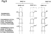
- Fig. 9 is an image diagram illustrating transmission optical signals after the transmission filtering processing in each stage when the set transmission bands illustrated in Fig. 8 are set in the transmitting-side optical transmission device 100 illustrated in Fig. 5 .
- the horizontal axis of the signals illustrated in Fig. 9 represents frequency, and the vertical axis represents signal strength.
- a transmission optical signal t12 illustrated in Fig. 9 becomes a transmission optical signal t12' having a signal band identical to the band 4s12 by the first-stage transmission filtering processing with the band 4s12 as the set transmission band.
- the band 5s1 being a set transmission band related to the next-stage transmission filtering processing covers the signal band of the transmission optical signal t12'. Accordingly, the signal band of a transmission optical signal t12" after the next-stage transmission filtering processing is the same as that of the transmission optical signal t12'.
- the lower limit of the signal band of the transmission optical signal t1m matches the lower limit of the band 4s1m by the first-stage transmission filtering processing with the band 4s1m as the set transmission band.
- the upper limit of the band 4s1m is set on the higher frequency side of the upper limit of the signal band of the transmission optical signal t1m. Accordingly, a shape of the transmission optical signal t1m in the neighborhood of the signal band upper limit is not affected by the first-stage transmission filtering processing. Accordingly, the shape of the transmission optical signal t1m in the neighborhood of the upper limit of the signal band becomes identical to a shape of the transmission optical signal tlm' after the first-stage transmission filtering processing in the neighborhood of the signal band upper limit.
- the neighborhood of the signal band lower limit of the transmission optical signal tlm' is within the band 5s1 and therefore is not affected by the next-stage transmission filtering processing. Accordingly, a shape of the transmission optical signal tlm" after the next-stage transmission filtering processing in the neighborhood of the signal band lower limit becomes identical to a shape of the transmission optical signal tlm' in the neighborhood of the signal band lower limit.
- the neighborhood of the signal band upper limit of the transmission optical signal tlm' is on the higher frequency side of the upper limit of the band 5s1. Accordingly, the upper limit of the transmission optical signal t1m" becomes identical to the upper limit of the band 5s1 by the next-stage transmission filtering processing.
- the signal band of the transmission optical signal tlm" after the next-stage transmission filtering processing is set by the lower limit of the band 4s1m and the upper limit of the band 5s1.
- the shape of the transmission optical signal t1m' in the neighborhood of the signal band upper limit is affected by the next-stage transmission filtering processing but is not affected by the first-stage transmission filtering processing. Accordingly, remarkable decrease in signal strength due to being affected twofold by the first-stage transmission filtering processing and the next-stage transmission filtering processing, as is the case in the transmission optical signal t1m" illustrated in Fig. 7 , does not occur in the shape of the transmission optical signal tlm" in the neighborhood of the signal band upper limit.
- the upper limit of a signal band of the transmission optical signal t21 is on the higher frequency side of the upper limit of the band 4s21. Accordingly, the upper limit of the signal band of the transmission optical signal t21 matches the upper limit of the band 4s21 by the first-stage transmission filtering processing with the band 4s21 as the set transmission band.
- the lower limit of the band 4s21 is set on the lower frequency side of the lower limit of the signal band of the transmission optical signal t21. Accordingly, a shape of the transmission optical signal t21 in the neighborhood of the signal band lower limit is not affected by the first-stage transmission filtering processing. Accordingly, a shape of a transmission optical signal t21' in the neighborhood of the signal band lower limit matches a shape of the transmission optical signal t21 after the first-stage transmission filtering processing in the neighborhood of the signal band lower limit.
- the lower limit of the signal band of the transmission optical signal t21' is set on the lower frequency side of the lower limit of the band 5s1. Accordingly, a shape of a transmission optical signal t21" after the next-stage transmission filtering processing in the neighborhood of the signal band lower limit becomes identical to a shape of the neighborhood of the lower limit of the band 5s1.
- a shape of the transmission optical signal t21' in the neighborhood of the signal band upper limit is set within the band 5s1. Accordingly, the shape of the transmission optical signal t21" after the next-stage transmission filtering processing in the neighborhood of the signal band upper limit becomes identical to the shape of the transmission optical signal t21' in the neighborhood of the signal band upper limit.
- the signal band of the transmission optical signal t21" after the next-stage transmission filtering processing is set by the upper limit of the band 4s21 and the lower limit of the band 5s1. Further, signal strength of the transmission optical signal t21" in the neighborhood of the signal band lower limit is affected by the next-stage transmission filtering processing but is not affected by the first-stage transmission filtering processing. Accordingly, remarkable decrease in signal strength due to being affected twofold by the first-stage transmission filtering processing and the next-stage transmission filtering processing, as is the case in the transmission optical signal t21" illustrated in Fig. 7 , does not occur in the shape of the transmission optical signal t21" in the neighborhood of the signal band upper limit.
- Fig. 10 is a diagram illustrating a second setting example of set transmission bands related to the first-stage transmission filtering processing and the next-stage transmission filtering processing, according to the second example embodiment.
- Diagram (a') in Fig. 10 illustrates the transmission optical signals t11 to tnm illustrated in Fig. 5 .
- Diagram (b) in Fig. 10 is an enlarged view of a part enclosed by broken lines illustrated in Diagram (a) in Fig. 10 .
- Diagram (c) in Fig. 10 is an image diagram illustrating transmission optical signals after undergoing the first-stage transmission filtering processing and the next-stage transmission filtering processing with set transmission bands illustrated in Diagram (b) in Fig. 10 .
- the transmission optical signal t1m and the transmission optical signal t21 are not optical signals of channels adjoining each other, and a a bandwidth not belonging to any channel exists between the two transmission optical signals.
- an empty channel not used in transmission of a transmission optical signal exists as the bandwidth.
- the empty channel is illustrated as a channel of the transmission optical signal t1(m+1)in Diagram (a') in Fig. 10 .
- the transmission optical signal t1(m+1) is an actually unused transmission optical signal and is an optical signal not input to the WSS_Band_MUX 106.
- a bandwidth of the empty channel is not limited to a case of a bandwidth being identical to those of other reception optical signals as illustrated.
- a frequency f4s1mb being the upper limit of the band 4s1m is set on the higher frequency side of a frequency f5s1b being the upper limit of the band 5s1.
- a frequency f4s21a being the lower limit of the band 4s21 is set on the higher frequency side of a frequency f5s2a being the lower limit of the band 5s2.
- the upper limit of the band 4s2m is set on the higher frequency side of a frequency f5s2b being the upper limit of the band 5s2.
- the lower limit of the band 4sn1 is set on the higher frequency side of a frequency f5sna being the lower limit of the band 5sn.
- a frequency f5s1a being the lower limit of the band 5s1 is set on the lower frequency side of the lower limit of the band 4s11.
- a frequency f5snb being the upper limit of the band 5sn is set on the higher frequency side of the upper limit of the band 4snm.
- An optical signal tlm" illustrated in Diagram (c) in Fig. 10 is the optical signal t1m illustrated in Fig. 5 undergoing the first-stage transmission filtering processing with the band 4s1m as a set transmission band and the next-stage transmission filtering processing with the band 5s1 as a set transmission band.
- Signal strength of the optical signal tlm" in the neighborhood of the upper limit of the signal band is affected by the next-stage transmission filtering processing but is not affected by the first-stage transmission filtering processing.
- Signal strength of the optical signal tlm" in the neighborhood of the lower limit of the signal band is affected by the first-stage transmission filtering processing but is not affected by the next-stage transmission filtering processing. Accordingly, the signal strength of the signal band of the optical signal t1m" in the neighborhood of the upper limit and the signal strength in the neighborhood of the lower limit do not exhibit remarkable decrease due to being affected by both the first-stage transmission filtering processing and the next-stage transmission filtering processing. Accordingly, the signal band of the optical signal t1m" is not narrowed as is the case with the signal band of the optical signal t1m" illustrated in Fig. 6 .
- a transmission optical signal t21" is the transmission optical signal t21 illustrated in Fig. 5 undergoing the first-stage transmission filtering processing with the band 4s21 as a set transmission band and the next-stage transmission filtering processing with the band 5s2 as a set transmission band.
- Both signal strength of the transmission optical signal t21" in the neighborhood of the upper limit of the signal band and signal strength in the neighborhood of the lower limit are affected by the first-stage transmission filtering processing but are not affected by the next-stage transmission filtering processing. Accordingly, the signal strength of the transmission optical signal t21" in the neighborhood of the upper limit of the signal band and the signal strength in the neighborhood of the lower limit do not exhibit remarkable decrease due to being affected by both the first-stage transmission filtering processing and the next-stage transmission filtering processing. Accordingly, the signal band of the transmission optical signal t21" is not narrowed as is the case with the signal band of the transmission optical signal t21" illustrated in Fig. 6 .
- Fig. 11 is a diagram illustrating a third setting example of set transmission bands related to the first-stage transmission filtering processing and the next-stage transmission filtering processing, according to the second example embodiment.
- Diagram (a') in Fig. 11 illustrates the transmission optical signals t11 to tnm illustrated in Fig. 5 .
- Diagram (b) in Fig. 11 is an enlarged view of a part enclosed by broken lines illustrated in Diagram (a) in Fig. 11 .
- Diagram (c) in Fig. 8 is an image diagram illustrating transmission optical signals after undergoing the first-stage transmission filtering processing and the next-stage transmission filtering processing with set transmission bands illustrated in Diagram (b) in Fig. 8 .
- the transmission optical signal t1m and the transmission optical signal t21 are not optical signals of channels adjoining each other, and a bandwidth not belonging to any channel exists between the two transmission optical signals.
- an empty channel not used in transmission of a transmission optical signal exists as the bandwidth.
- the empty channel is illustrated as a channel of the transmission optical signal t1(m+1) in Diagram (a') in Fig. 11 .
- the transmission optical signal t1(m+1) is an actually unused transmission optical signal and is an optical signal not input to the WSS_Band_MUX 106.
- a bandwidth of the empty channel is not limited to a case of being a bandwidth being identical to those of other reception optical signals as illustrated.
- a frequency f4s1mb being the upper limit of the band 4s1m is set on the lower frequency side of a frequency f5s1b being the upper limit of the band 5s1.
- a frequency f4s21a being the lower limit of the band 4s21 is set on the lower frequency side of a frequency f5s2a being the lower limit of the band 5s2.
- the upper limit of the band 4s2m is set on the lower frequency side of a frequency f5s2b being the upper limit of the band 5s2.
- the lower limit of the band 4sn1 is set on the higher frequency side of a frequency f5sna being the lower limit of the band 5sn.
- a frequency f5s1a being the lower limit of the band 5s1 is set on the lower frequency side of the lower limit of the band 4s11.
- a frequency f5snb being the upper limit of the band 5sn is set on the higher frequency side of the upper limit of the band 4snm.
- An optical signal tlm" illustrated in Diagram (c) in Fig. 11 is the optical signal t1m illustrated in Fig. 5 undergoing the first-stage transmission filtering processing with the band 4s1m as a set transmission band and the next-stage transmission filtering processing with the band 5s1 as a set transmission band.
- Both signal strength of the optical signal tlm" in the neighborhood of the upper limit of the signal band and signal strength in the neighborhood of the lower limit are affected by the first-stage transmission filtering processing but are not affected by the next-stage transmission filtering processing. Accordingly, the signal strength of the optical signal tlm" in the neighborhood of the upper limit of the signal band and the signal strength in the neighborhood of the lower limit do not exhibit remarkable decrease due to being affected by both the first-stage transmission filtering processing and the next-stage transmission filtering processing. Accordingly, the signal band of the optical signal tlm" is not narrowed as is the case with the signal band of the optical signal tlm" illustrated in Fig. 6 .
- a transmission optical signal t21" is the transmission optical signal t21 illustrated in Fig. 5 undergoing the first-stage transmission filtering processing with the band 4s21 as a set transmission band and the next-stage transmission filtering processing with the band 5s2 as a set transmission band.
- Signal strength of the transmission optical signal t21" in the neighborhood of the upper limit of the signal band is affected by the first-stage transmission filtering processing but is not affected by the next-stage transmission filtering processing.
- Signal strength of the transmission optical signal t21" in the neighborhood of the lower limit of the signal band is affected by the next-stage transmission filtering processing but is not affected by the first-stage transmission filtering processing. Accordingly, the signal strength of the transmission optical signal t21" in the neighborhood of the upper limit of the signal band and the signal strength in the neighborhood of the lower limit do not exhibit remarkable decrease due to being affected by both the first-stage transmission filtering processing and the next-stage transmission filtering processing. Accordingly, the signal band of the transmission optical signal t21" is not narrowed as is the case with the signal band of the transmission optical signal t21" illustrated in Fig. 6 .
- Fig. 12 is a conceptual diagram illustrating general set transmission bands related to the first-stage reception filtering processing and the next-stage reception filtering processing.
- Diagram (a') in Fig. 12 illustrates reception optical signals in the first-stage multiplexed reception optical signals.
- the transmission optical signals t11 to tnm illustrated in Fig. 5 are illustrated.
- Diagram (b) in Fig. 12 is an enlarged view of a part enclosed by broken lines illustrated in Diagram (a) in Fig. 12 .
- Diagram (b) in Fig. 12 is an enlarged view of a part enclosed by broken lines illustrated in Diagram (a) in Fig. 8 .
- Diagram (c) in Fig. 12 is an image diagram illustrating reception optical signals in the set transmission bands illustrated in Diagram (b) in Fig. 12 after undergoing the first-stage transmission filtering processing and the next-stage transmission filtering processing.
- each of bands 5r1 to 5rn is a set transmission band related to the first-stage reception filtering processing performed on each of the next-stage multiplexed reception optical signals.
- the next-stage multiplexed reception optical signal is acquired by demultiplexing the aforementioned first-stage multiplexed reception optical signal in the WSS_Band_DEMUX 206 illustrated in Fig. 5 .
- each of bands 4r11 to 4r1m represents the set transmission band related to the aforementioned next-stage reception filtering processing.
- the next-stage reception filtering processing is performed on each reception optical signal acquired by demultiplexing the next-stage multiplexed reception optical signal in the WSS_CH_DEMUX 201.
- bands 4r21 to 4r2m and bands 4rn1 to 4rnm are same.
- a frequency f4rlmb being the upper limit of the band 4r1m roughly matches a frequency f5r1b being the upper limit of the band 5r1.
- a frequency f4r21a being the lower limit of the band 4r21 roughly matches a frequency f5r2a being the lower limit of the band 5r2.
- a frequency f5r2b being the upper limit of the band 5r2 roughly matches the upper limit of the band 4r2m.
- a frequency f5rna being the lower limit of the band 5rn roughly matches the lower limit of the band 4rn1.
- a frequency f5rla being the lower limit of the band 5r1 is set on the lower frequency side of the lower limit of the band 4r11.
- a frequency f5rnb being the upper limit of the band 5rn is set on the higher frequency side of the band 4rnm.
- a reception optical signal r1m illustrated in Diagram (c) in Fig. 12 is the reception optical signal r1m illustrated in Fig. 5 undergoing the first-stage transmission filtering processing with the band 4s1m as a set transmission band and the next-stage reception filtering processing with the band 5s1 as a set transmission band.
- Signal strength of the reception optical signal r1m in the neighborhood of the upper limit of the signal band is remarkably decreased due to being affected by both the first-stage transmission filtering processing and the next-stage reception filtering processing. Consequently, the signal band of the reception optical signal r1m is narrowed.
- a reception optical signal r21 is the reception optical signal r21 illustrated in Fig. 5 undergoing the first-stage transmission filtering processing with the band 4s21 as a set transmission band and the next-stage reception filtering processing with the band 5s2 as a set transmission band.
- Signal strength of the reception optical signal r21 in the neighborhood of the lower limit of the signal band is remarkably decreased due to being affected by both the first-stage transmission filtering processing and the next-stage reception filtering processing. Consequently, the signal band of the reception optical signal r21 is narrowed.
- Fig. 13 is an image diagram illustrating signals in each stage after the reception filtering processing is performed when the set transmission bands illustrated in Fig. 12 are set in the receiving-side optical transmission device 200 illustrated in Fig. 5 .
- the horizontal axis of the signals illustrated in Fig. 13 represents frequency, and the vertical axis represents signal strength.
- the signal band of a reception optical signal r12" before the first-stage reception filtering processing is included in the band 5r1. Accordingly, the reception optical signal r12" becomes a reception optical signal r12' having a signal band identical to the signal band of the reception optical signal r12", without being affected by the first-stage reception filtering processing with the band 5r1 as the set transmission band.
- the reception optical signal r12' is an optical signal multiplexed in the next-stage multiplexed reception optical signal.
- the band 4r12 being a set transmission band related to the next-stage reception filtering processing is covered by a signal band of the reception optical signal r12'. Accordingly, the signal band of a reception optical signal r12" after the next-stage reception filtering processing becomes identical to the band 4r12.
- the signal band upper limit of a reception optical signal r1m" is on the higher frequency side of the upper limit of the band 5r1 being a set transmission band related to the first-stage reception filtering processing. Accordingly, the signal band upper limit of a reception optical signal r1m' after the first-stage reception filtering processing becomes identical to the upper limit of the band 5r1.
- the signal band lower limit of the reception optical signal r1m" is within the band 5r1. Accordingly, a shape of the reception optical signal r1m' after the first-stage reception filtering processing in the neighborhood of the signal band lower limit becomes identical to a shape of the reception optical signal r1m" in the neighborhood of the signal band lower limit.
- the signal band upper limit of the reception optical signal r1m' is identical to the upper limit of the band 4r1m being a set transmission band related to the next-stage reception filtering processing. Accordingly, signal strength of a reception optical signal r1m after the next-stage reception filtering processing in the neighborhood of the signal band upper limit is remarkably decreased due an effect of the twofold filtering processing. Consequently, the reception optical signal r1m has a remarkably narrowed signal band compared with the reception optical signal r12.
- the signal band lower limit of the reception optical signal r1m' is on the lower frequency side of the lower limit of the band 4rlm. Accordingly, the signal band lower limit of the reception optical signal r1m after the next-stage reception filtering processing becomes identical to the lower limit of the band 4r1m.
- the signal band lower limit of a reception optical signal r21" is on the lower frequency side of the lower limit of the band 5r2 being a set transmission band related to the first-stage reception filtering processing. Accordingly, the lower limit of a reception optical signal r21' after the first-stage reception filtering processing becomes identical to the lower limit of the band 5r2.
- the signal band upper limit of the reception optical signal r21" is within the band 5r2. Accordingly, a shape of the reception optical signal r21' after the first-stage reception filtering processing in the neighborhood of the signal band upper limit becomes identical to a shape of the reception optical signal r21" in the neighborhood of the signal band upper limit.
- the signal band lower limit of the reception optical signal r21' is identical to the lower limit of the band 4r21 being a set transmission band related to the next-stage reception filtering processing. Accordingly, signal strength of a reception optical signal r21 after the next-stage reception filtering processing in the neighborhood of the signal band lower limit is remarkably decreased due to an effect of the twofold filtering processing. Consequently, the reception optical signal r21 has a remarkably narrowed signal band compared with the reception optical signal r12.
- the signal band upper limit of the reception optical signal r21' is on the higher frequency side of the upper limit of the band 4r21. Accordingly, the signal band upper limit of the reception optical signal r21 after the next-stage reception filtering processing becomes identical to the upper limit of the band 4r21.
- a signal band of a reception optical signal after the next-stage reception filtering processing may be remarkably narrowed.
- Fig. 14 is a diagram illustrating a first setting example of set transmission bands related to the first-stage reception filtering processing and the next-stage reception filtering processing, according to the second example embodiment.
- Diagram (a') in Fig. 14 illustrates reception optical signals in the first-stage multiplexed reception optical signals.
- Diagram (b) in Fig. 14 is an enlarged view of a part enclosed by broken lines illustrated in Diagram (a) in Fig. 14 .
- Diagram (c) in Fig. 14 is an image diagram illustrating reception optical signals after undergoing the first-stage reception filtering processing and the next-stage reception filtering processing with set transmission bands illustrated in Diagram (b) in Fig. 14 .
- Each of bands 5r1 to 5rn illustrated in Diagram (a) in Fig. 14 is a set transmission band related to the first-stage reception filtering processing.
- the first-stage reception filtering processing is performed on each of the next-stage multiplexed reception optical signals acquired by demultiplexing the aforementioned first-stage multiplexed reception optical signal in the WSS_Band_DEMUX 206 illustrated in Fig. 5 .
- Each of bands 4r11 to 4r1m represents the set transmission band related to the aforementioned next-stage reception filtering processing performed on each reception optical signal acquired by demultiplexing the next-stage multiplexed reception optical signal in the WSS_CH_DEMUX 201.
- a frequency f4rlmb being the upper limit of the band 4r1m is set on the higher frequency side of a frequency f5r1b being the upper limit of the band 5r1.
- a frequency f4r21a being the lower limit of the band 4r21 is set on the lower frequency side of a frequency f5r2a being the lower limit of the band 5r2.
- the upper limit of the band 4r2m is set on the higher frequency side of the upper limit of a frequency f5r2b being the upper limit of the band 5r2.
- the lower limit of the band 4rn1 is set on the lower frequency side of the lower limit of the band 5rn.
- a frequency f5rla being the lower limit of the band 5r1 is set on the lower frequency side of the lower limit of the band 4r11.
- a frequency f5rnb being the upper limit of the band 5rn is set on the higher frequency side of the band 4rnm.
- a reception optical signal r1m illustrated in Diagram (c) in Fig. 14 is the reception optical signal r1m illustrated in Fig. 5 undergoing the first-stage transmission filtering processing with the band 4s1m as a set transmission band and the next-stage reception filtering processing with the band 5s1 as a set transmission band.
- Signal strength of the reception optical signal r1m in the neighborhood of the upper limit of the signal band is affected by the first-stage reception filtering processing but is not affected by the next-stage reception filtering processing.
- Signal strength of the reception optical signal r1m in the neighborhood of the lower limit of the signal band is affected by the next-stage reception filtering processing but is not affected by the first-stage reception filtering processing. Accordingly, the signal band of the reception optical signal r1m is not narrowed as is the case with the reception optical signal r1m illustrated in Fig. 12 .
- a reception optical signal r21 is the reception optical signal r21 illustrated in Fig. 5 undergoing the first-stage reception filtering processing with the band 4s21 as a set transmission band and the next-stage reception filtering processing with the band 5s2 as a set transmission band.
- Signal strength of the reception optical signal r21 in the neighborhood of the lower limit of the signal band is affected by the first-stage reception filtering processing but is not affected by the next-stage reception filtering processing.
- Signal strength of the reception optical signal r21 in the neighborhood of the upper limit of the signal band is affected by the next-stage reception filtering processing but is not affected by the first-stage reception filtering processing. Accordingly, the signal band of the reception optical signal r21 is not narrowed as is the case with the reception optical signal r21 illustrated in Fig. 12 .
- Fig. 15 is an image diagram illustrating signals in each stage after reception filtering processing when the set transmission band illustrated in Fig. 14 are set in the receiving-side optical transmission device 200 illustrated in Fig. 5 .
- the horizontal axis of the signals illustrated in Fig. 15 represents frequency, and the vertical axis represents signal strength.
- the signal band of a reception optical signal r12" before the first-stage reception filtering processing is included in the band 5r1. Accordingly, the reception optical signal r12" is not affected by the first-stage reception filtering processing with the band 5r1 as the set transmission band. Accordingly, the signal band of a reception optical signal r12' after the first-stage reception filtering processing becomes identical to the signal band of the reception optical signal r12".
- the reception optical signal r12' is an optical signal multiplexed in the next-stage multiplexed reception optical signal.
- the band 4r12 being a set transmission band related to the next-stage reception filtering processing is covered by the signal band of the reception optical signal r12'. Accordingly, the signal band of a reception optical signal r12 after the next-stage reception filtering processing becomes identical to the band 4r12.
- the signal band upper limit of a reception optical signal r1m" is on the higher frequency side of the upper limit of the band 5r1 being a set transmission band related to the first-stage reception filtering processing. Accordingly, the signal band upper limit of a reception optical signal r1m' after the first-stage reception filtering processing becomes identical to the upper limit of the band 5r1.
- the signal band lower limit of the reception optical signal r1m" is within the band 5r1. Accordingly, a shape of the reception optical signal r1m' after the first-stage reception filtering processing in the neighborhood of the signal band lower limit is identical to a shape of the reception optical signal r1m" in the neighborhood of the signal band lower limit.
- the signal band lower limit of the reception optical signal r1m' is on the lower frequency side of the lower limit of the band 4rlm being a set transmission band related to the next-stage reception filtering processing. Accordingly, the signal band lower limit of a reception optical signal r1m after the next-stage reception filtering processing becomes identical to the lower limit of the band 4r1m.
- the signal band upper limit of the reception optical signal r1m" is on the higher frequency side of the upper limit of the band 5r1. Accordingly, the signal band upper limit of the reception optical signal r1m' after the first-stage reception filtering processing becomes identical to the band 5r1.
- the signal band upper limit of the reception optical signal r1m' is within the band 4r1m. Accordingly, a shape of the reception optical signal r1m after the next-stage reception filtering processing in the neighborhood of the signal band upper limit becomes identical to a shape of the reception optical signal r1m' in the neighborhood of the signal band upper limit.
- the signal band of the reception optical signal r1m after the next-stage reception filtering processing is set by the lower limit of the band 4r1m and the upper limit of the band 5r1. Further, the neighborhood of the lower limit of the signal band of the reception optical signal r1m is affected by the next-stage reception filtering processing but is not affected by the first-stage reception filtering processing. Accordingly, remarkable narrowing of a signal band due to being affected twofold by the first-stage reception filtering processing and the next-stage reception filtering processing, as is the case in the reception optical signal r1m illustrated in Fig. 13 , does not occur in the neighborhood of the upper limit of the signal band of the reception optical signal r1m.
- the signal band lower limit of a reception optical signal r21" is on the lower frequency side of the lower limit of the band 5r2 being a set transmission band related to the first-stage reception filtering processing. Accordingly, the lower limit of a reception optical signal r21' after first-stage reception filtering processing becomes identical to the lower limit of the band 5r2.
- the signal band upper limit of the reception optical signal r21 is within the band 5r2. Accordingly, a shape of the reception optical signal r21' after the first-stage reception filtering processing in the neighborhood of the signal band upper limit becomes identical to a shape of the reception optical signal r21" in the neighborhood of the signal band upper limit.
- the signal band lower limit of the reception optical signal r21' is within the band 4r21 being a set transmission band related to the next-stage reception filtering processing. Accordingly, a shape of the reception optical signal r21 after the next-stage reception filtering processing in the neighborhood of the signal band lower limit becomes identical to a shape of the reception optical signal r21' in the neighborhood of the signal band lower limit.
- the signal band upper limit of the reception optical signal r21' is on the higher frequency side of the upper limit of the band 4r21. Accordingly, the signal band upper limit of the reception optical signal after the next-stage reception filtering processing r21 becomes identical to the upper limit of the band 4r21.
- the signal band of the reception optical signal r21 after the next-stage reception filtering processing is set by the upper limit of the band 4r21 and the lower limit of the band 5r2. Further, the neighborhood of the lower limit of the signal band of the reception optical signal r21 is affected by the next-stage reception filtering processing but is not affected by the first-stage reception filtering processing. Accordingly, remarkable narrowing of a signal band due to being affected twofold by the first-stage reception filtering processing and the next-stage reception filtering processing, as is the case in the reception optical signal r21 illustrated in Fig. 13 , does not occur in the neighborhood of the upper limit of the signal band of the reception optical signal r21.
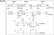
- Fig. 16 is a conceptual diagram illustrating a second setting example of set transmission bands related to the first-stage reception filtering processing and the next-stage reception filtering processing, according to the present example embodiment.
- Diagram (a') in Fig. 16 illustrates reception optical signals in the first-stage multiplexed reception optical signals.
- Diagram (b) in Fig. 16 is an enlarged view of a part enclosed by broken lines illustrated in Diagram (a) in Fig. 16 .
- Diagram (c) in Fig. 16 is an image diagram illustrating reception optical signals after undergoing the first-stage transmission filtering processing and the next-stage reception filtering processing with set transmission bands illustrated in Diagram (b) in Fig. 16 .
- a reception optical signal r1m" and a reception optical signal r21" are not optical signals of channels adjoining each other, and a bandwidth not belonging to any channel exists between the two reception optical signals.
- an empty channel not used in reception of a reception optical signal exists as the bandwidth.
- the empty channel is illustrated as a channel of a reception optical signal r1(m+1)" in Diagram (a') in Fig. 16 .
- the reception optical signal r1(m+1)" is an actually unused reception optical signal and is a reception optical signal not output from the WSS_CH_DEMUXes.
- a bandwidth of the empty channel is not limited to a case of a bandwidth being identical to those of other reception optical signals as illustrated.
- Each of bands 5r1 to 5rn illustrated in Diagram (a) in Fig. 16 is a set transmission band related to the first-stage reception filtering processing.
- the first-stage reception filtering processing is performed on each of the next-stage multiplexed reception optical signals acquired by demultiplexing the aforementioned first-stage multiplexed reception optical signal in the WSS_Band_DEMUX 206 illustrated in Fig. 5 .
- Each of bands 4r11 to 4rlm represents the set transmission band related to the aforementioned next-stage reception filtering processing performed on each of reception optical signals acquired by demultiplexing the next-stage multiplexed reception optical signal in the WSS_CH_DEMUX 201.
- a frequency f4r1mb being a frequency on the edge of the higher frequency side of the band 4rlm is set on the higher frequency side of a frequency f5rlb being the upper limit of the band 5r1.
- a frequency f4r21a being the lower limit of the band 4r21 is set within the band 5r2.
- the upper limit of the band 4r2m is set on the higher frequency side of a frequency f5r2b being the upper limit of the band 5r2.
- the lower limit of the band 4rn1 is set within the band 5rn.
- a frequency f5rla being the lower limit of the band 5r1 is set on the lower frequency side of the lower limit of the band 4r11.
- a frequency f5rnb being the upper limit of the band 5rn is set on the higher frequency side of the band 4rnm.
- a reception optical signal r1m illustrated in Diagram (c) in Fig. 16 is the reception optical signal r1m illustrated in Fig. 5 undergoing the first-stage transmission filtering processing with the band 4s1m as a set transmission band and the next-stage reception filtering processing with the band 5s1 as a set transmission band.
- Signal strength of the reception optical signal r1m in the neighborhood of the upper limit of the signal band is affected by the first-stage reception filtering processing but is not affected by the next-stage reception filtering processing.
- Signal strength of the reception optical signal r1m in the neighborhood of the lower limit of the signal band is affected by the next-stage reception filtering processing but is not affected by the first-stage reception filtering processing. Accordingly, the signal band of the reception optical signal r1m is not narrowed as is the case with the reception optical signal r1m illustrated in Fig. 12 .
- a reception optical signal r21 is the reception optical signal r21 illustrated in Fig. 5 undergoing the first-stage reception filtering processing with the band 4s21 as a set transmission band and the next-stage reception filtering processing with the band 5s2 as a set transmission band.
- Both signal strength of the reception optical signal r21 in the neighborhood of the lower limit of the signal band and signal strength in the neighborhood of the upper limit are affected by the next-stage reception filtering processing but are not affected by the first-stage reception filtering processing. Accordingly, the signal band of the reception optical signal r21 is not narrowed as is the case with the reception optical signal r21 illustrated in Fig. 12 .
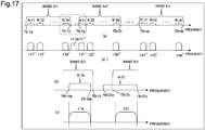
- Fig. 17 is a diagram illustrating a third setting example of set transmission bands related to the first-stage reception filtering processing and the next-stage reception filtering processing, according to the present example embodiment.
- Diagram (a') in Fig. 17 illustrates reception optical signals in the first-stage multiplexed reception optical signals.
- Diagram (b) in Fig. 17 is an enlarged view of a part enclosed by broken lines illustrated in Diagram (a) in Fig. 17 .
- Diagram (c) in Fig. 12 is an image diagram illustrating reception optical signals after undergoing the first-stage reception filtering processing and the next-stage reception filtering processing with set transmission bands illustrated in Diagram (b) in Fig. 12 .
- a reception optical signal r1m" and a reception optical signal r21" are not optical signals of channels adjoining each other, and a bandwidth not belonging to any channel exists between the two reception optical signals.
- an empty channel not used in reception of a reception optical signal exists as the bandwidth.
- the empty channel is illustrated as a channel of a reception optical signal r1(m+1)" in Diagram (a') in Fig. 17 .
- the reception optical signal r1(m+1)" is an actually unused reception optical signal and is a reception optical signal not output from the WSS_CH_DEMUXes.
- a bandwidth of the empty channel is not limited to a case of a bandwidth being identical to those of other reception optical signals as illustrated.
- Each of bands 5r1 to 5rn illustrated in Diagram (a) in Fig. 17 is a set transmission band related to the first-stage reception filtering processing.
- the first-stage reception filtering processing is performed on each of the next-stage multiplexed reception optical signals acquired by demultiplexing the aforementioned first-stage multiplexed reception optical signal in the WSS_Band_DEMUX 206 illustrated in Fig. 5 .
- Each of bands 4r11 to 4rlm represents the set transmission band related to the aforementioned next-stage reception filtering processing performed on each reception optical signal acquired by demultiplexing the next-stage multiplexed reception optical signal in the WSS_CH_DEMUX 201.
- a frequency f4rlmb being the upper limit of the band 4rlm is set within the band 5r1.
- a frequency f4r21a being the lower limit of the band 4r21 is set on the lower frequency side of a frequency f5r2a being the lower limit of the band 5r2.
- the upper limit of the band 4r2m is set within the band 5r2.
- the lower limit of the band 4rn1 is set on the lower frequency side of a frequency f5rna being the lower limit of the band 5rn.
- a frequency f5rla being the lower limit of the band 5r1 is set on the lower frequency side of the lower limit of the band 4r11.
- a frequency f5rnb being the upper limit of the band 5rn is set on the higher frequency side of the upper limit of the band 4rnm.
- a reception optical signal r1m illustrated in Diagram (c) in Fig. 17 is the reception optical signal r1m illustrated in Fig. 5 undergoing the first-stage transmission filtering processing with the band 4s1m as a set transmission band and the next-stage reception filtering processing with the band 5s1 as a set transmission band.
- Both signal strength of the reception optical signal r1m in the neighborhood of the upper limit of the signal band and signal strength in the neighborhood of the lower limit are affected by the next-stage reception filtering processing but are not affected by the first-stage reception filtering processing. Accordingly, the signal band of the reception optical signal r1m is not narrowed as is the case with the reception optical signal r1m illustrated in Fig. 12 .
- a reception optical signal r21 is the reception optical signal r21 illustrated in Fig. 5 undergoing the first-stage reception filtering processing with the band 4s21 as a set transmission band and the next-stage reception filtering processing with the band 5s2 as a set transmission band.
- Signal strength of the reception optical signal r21 in the neighborhood of the lower limit of the signal band is affected by the next-stage reception filtering processing but is not affected by the first-stage reception filtering processing.
- Signal strength of the reception optical signal r21 in the neighborhood of the upper limit of the signal band is affected by the next-stage reception filtering processing but is not affected by the first-stage reception filtering processing. Accordingly, the signal band of the reception optical signal r21 is not narrowed as is the case with the reception optical signal r21 illustrated in Fig. 12 .
- Three-or-more-stage transmission filtering processing may be performed on transmission optical signals in the optical transmission device for transmission.
- edges of set transmission bands related to transmission filtering processing in every stage are set in such a way as not to overlap one another.
- the optical transmission device for reception may include a three-or-more-stage optical demultiplexing device.
- three-or-more-stage transmission filtering processing may be performed on reception optical signals in the optical transmission device for reception.
- edges of set transmission bands related to reception filtering processing in every stage are set in such a way as not to overlap one another.
- each of the transmitting-side optical transmission device and the receiving-side optical transmission device included in the optical communication system according to the present example embodiment all edges of set transmission bands related to multistage filtering processing of optical signals are set in such a way as not to overlap one another. Accordingly, the optical communication system may suppress remarkable decrease in signal strength of an optical signal at a frequency in the neighborhood of overlapping edges, the decrease being caused by overlapping of edges of set transmission bands related to multistage filtering processing. Accordingly, the optical communication system may suppress narrowing of a signal band of the optical signal accompanying the decrease in signal strength.
- a third example embodiment is an example embodiment related to an optical communication system automatically setting edges of set transmission bands related to multistage filtering processing of optical signals in such a way that the edges do not overlap one another.
- Fig. 18 is a conceptual diagram illustrating a configuration of an optical communication system 800 being an example of an optical communication system according to the third example embodiment.
- a description of the optical communication system 800 illustrated in Fig. 18 is the same as the description of the optical communication system 800 illustrated in Fig. 5 except for the following description.
- the following description is inconsistent with the description of the second example embodiment, the following description has priority.
- the optical communication system 800 illustrated in Fig. 18 includes control units 170 and 270.
- the control unit 170 acquires information indicating set transmission bands related to each stage of transmission filtering processing from each of WSS_CH_MUXes 101 to 10n (first-stage transmission WSSs) and a WSS_Band_MUX 106 (next-stage transmission WSS). Then, the control unit 170 extracts an edge of a set transmission band related to the first-stage transmission filtering processing and an edge of a set transmission band related to the next-stage transmission filtering processing overlapping each other. Then, when extracting overlapping edges, the control unit 170 transmits control information instructing widening of a set transmission band including the edge to a first-stage transmission WSS performing the first-stage transmission filtering processing on the set transmission band.
- the widening is widening of the upper limit of the set transmission band toward the higher frequency side.
- the widening is widening of the lower limit of the set transmission band toward the lower frequency side.
- the first-stage transmission WSS receiving the transmission of the control information widens the set transmission band related to the first-stage transmission filtering processing in accordance with the control information.
- the control unit 270 acquires information indicating set transmission bands related to each stage of reception filtering processing from a WSS_Band_DEMUX 206 (first-stage reception WSS) and each of WSS_CH_DEMUXes 201 to 20n (next-stage reception WSSs). Then, the control unit 270 extracts an edge of a set transmission band related to the first-stage reception filtering processing and an edge of a set transmission band related to the next-stage reception filtering processing overlapping each other. Then, when extracting overlapping edges, the control unit 120 transmits control information instructing widening of a set transmission band including the edge to a next-stage reception WSS performing the next-stage reception filtering processing on the set transmission band.
- the widening is widening of the upper limit of the set transmission band toward the higher frequency side.
- the widening is widening of the lower limit of the set transmission band toward the lower frequency side.
- the next-stage reception WSS receiving the transmission of the control information widens the set transmission band related to the next-stage reception filtering processing in accordance with the control information.
- Fig. 19 is a conceptual diagram illustrating a processing flow of processing performed by either one of the control units 170 and 270 (hereinafter simply referred to as a "control unit").
- control unit starts the processing illustrated in Fig. 19 by external input of start information.
- the control unit determines whether a transmission band of each filter is set in each WSS included in a target optical transmission device (a transmitting-side optical transmission device 100 or a receiving-side optical transmission device 200).
- the control unit makes the determination by, for example, acquiring setting completion information from each WSS.
- control unit acquires and stores every set transmission band set in each WSS included in the target optical transmission device, as the processing.
- the control unit specifies the upper limit of each lower level transmission band included in the target optical transmission device.
- the lower level transmission band refers to a set transmission band related to filtering processing in the first-stage transmission WSS or the next-stage reception WSS.
- the control unit specifies the upper limit of each lower level transmission band.
- the higher level transmission band refers to a set transmission band related to filtering processing in the next-stage transmission WSS or the first-stage reception WSS.
- the control unit extracts a lower level transmission band making the difference between the upper limit of the lower level transmission band specified by the processing in S103 and the upper limit of the higher level transmission band specified by the processing in S104 equal to or less than a threshold value Th1.
- the threshold value Th1 is a threshold value predetermined under an assumption that two upper limits match when the difference between the two upper limits is equal to or less than the threshold value Th1.
- control unit instructs each lower level WSS performing filtering processing related to each lower level transmission band extracted by the processing in S105 to change the upper limit of the relating lower level transmission band to a higher frequency value.
- the lower level WSS receiving the instruction changes the upper limit of the target lower level transmission band in accordance with the instruction.
- control unit specifies the lower limit of each lower level transmission band included in the target optical transmission device.
- control unit specifies the lower limit of each higher level transmission band.
- the control unit extracts a lower level transmission band making the difference between the lower limit of the lower level transmission band specified by the processing in S107 and the lower limit of the higher level transmission band specified by the processing in S108 equal to or less than a threshold value Th2.
- the threshold value Th2 is a threshold value predetermined under an assumption that two lower limits match when the difference between the two lower limits is equal to or less than the threshold value Th2.
- control unit instructs each lower level WSS performing filtering processing related to each lower level transmission band extracted by the processing in S110 to change the lower limit of the relating lower level transmission band to a lower frequency value.
- the lower level WSS receiving the instruction changes the lower limit of the target lower level transmission band in accordance with the instruction.
- control unit ends the processing illustrated in Fig. 19 .
- the optical communication system according to the third example embodiment has a configuration similar to that of the optical communication system according to the second example embodiment and provides effects similar to those of the optical communication system according to the second example embodiment.
- the third example embodiment may enable automatic setting of set transmission bands for providing the aforementioned effects.
- a fourth example embodiment is an example embodiment related to an optical transmission device adjusting set transmission bands in each WSS by monitoring the aforementioned next-stage transmission optical multiplexed signal.
- Fig. 20 is a conceptual diagram illustrating a configuration of an optical transmission device 190 being an example of an optical transmission device according to the fourth example embodiment.
- the optical transmission device 190 includes a transmitting-side optical transmission device 100 and a control unit 170.
- the transmitting-side optical transmission device 100 includes an optical coupler 161 and a signal monitor 162.
- the optical coupler 161 splits part of the aforementioned next-stage transmission multiplexed optical signal transmitted from a WSS_Band_MUX 106 to a transmission line 300 and inputs the split signal to the signal monitor 162.
- the signal monitor 162 is an optical channel monitor (OCM).
- OCM optical channel monitor
- the signal monitor 162 measures a frequency characteristic of signal strength of a next-stage multiplexed transmission optical signal input from the optical coupler 161. Then, the signal monitor 162 inputs information indicating the measured frequency characteristic to the control unit 170.
- control unit 170 specifies an upper limit or a lower limit of a set transmission band related to the first-stage transmission filtering processing to be changed.
- control unit 170 transmits, to a lower level WSS relating to the specified upper limit or lower limit, a control signal instructing change of the upper limit or the lower limit of the set transmission band.
- a lower level WSS is each of WSS_CH_MUXes 101 to 10n illustrated in Fig. 20 .
- a frequency band for each channel is allocated to each lower level WSS.
- the optical transmission device 190 may be configured as an OCI.
- a description of the transmitting-side optical transmission device 100 and the control unit 170 illustrated in Fig. 20 is the same as the description of the transmitting-side optical transmission device 100 and the control unit 170 illustrated in Fig. 18 except for the above description.
- the above description is inconsistent with the description of the third example embodiment, the above description has priority.
- the optical transmission device monitors a frequency characteristic of the next-stage multiplexed transmission optical signal. Then, from the monitored characteristic, the optical transmission device specifies an upper limit or a lower limit to be changed out of upper limits and lower limits of set transmission bands related to the first-stage reception filtering processing and causes a relating lower level WSS to change the upper limit or the lower limit. Accordingly, for example, even when the control unit does not acquire channel information indicating a set transmission band related to the first-stage reception filtering processing in each lower level WSS from each transmission unit, the optical transmission device may adjust the set transmission band by monitoring the next-stage multiplexed transmission optical signal.
- Fig. 21 is a block diagram illustrating an optical transmission device 100x being a minimum configuration of the optical transmission device according to the example embodiments.
- the optical transmission device 100x includes a first multiplexing device 101x and a second multiplexing device 106x.
- the first multiplexing device 101x outputs a first wavelength multiplexed signal acquired by multiplexing first processed signals acquired by performing first filtering processing on input transmission optical signals.
- the second multiplexing device 106x outputs a second wavelength multiplexed signal acquired by multiplexing the first wavelength multiplexed signals undergoing second filtering processing.
- each first transmission band being a transmission band related to each operation of the first filtering processing are respectively different from the upper limit and the lower limit of each second transmission band being a transmission band related to each operation of the second filtering processing.
- the optical transmission device 100x none of the upper limits and the lower limits of the set transmission bands related to the first filtering processing overlap any of the upper limits and the lower limits of the set transmission bands related to the next-stage transmission filtering processing. Accordingly, every upper limit and upper limit of a signal band of a transmission optical signal included in a multiplexed transmission optical signal output from the optical transmission device is determined by either the first filtering processing or the second filtering processing. In other words, none of the upper limits and the lower limits are affected by twofold filtering processing by the first filtering processing and the second filtering processing. Accordingly, the optical transmission device may suppress narrowing of a signal band of a transmission optical signal due to the twofold filtering processing.
- the optical transmission device 100x provides the effect described in the Advantageous Effects of Invention section.
Landscapes
- Engineering & Computer Science (AREA)
- Computer Networks & Wireless Communication (AREA)
- Signal Processing (AREA)
- Physics & Mathematics (AREA)
- Electromagnetism (AREA)
- Optical Communication System (AREA)
- Optical Filters (AREA)
Applications Claiming Priority (2)
| Application Number | Priority Date | Filing Date | Title |
|---|---|---|---|
| JP2018087295 | 2018-04-27 | ||
| PCT/JP2019/016753 WO2019208413A1 (ja) | 2018-04-27 | 2019-04-19 | 光伝送装置、光受信装置、光通信システム、光伝送方法、設定方法及びコンピュータ可読媒体 |
Publications (2)
| Publication Number | Publication Date |
|---|---|
| EP3787205A1 true EP3787205A1 (de) | 2021-03-03 |
| EP3787205A4 EP3787205A4 (de) | 2021-06-30 |
Family
ID=68293801
Family Applications (1)
| Application Number | Title | Priority Date | Filing Date |
|---|---|---|---|
| EP19793040.7A Withdrawn EP3787205A4 (de) | 2018-04-27 | 2019-04-19 | Optische übertragungsvorrichtung, optische empfangsvorrichtung, optisches kommunikationssystem, optisches übertragungsverfahren, einstellverfahren und computerlesbares medium |
Country Status (4)
| Country | Link |
|---|---|
| US (1) | US20210050929A1 (de) |
| EP (1) | EP3787205A4 (de) |
| JP (1) | JP7107366B2 (de) |
| WO (1) | WO2019208413A1 (de) |
Families Citing this family (2)
| Publication number | Priority date | Publication date | Assignee | Title |
|---|---|---|---|---|
| CN113346976B (zh) * | 2020-03-02 | 2024-04-12 | 华为技术有限公司 | 一种频谱资源配置的方法、网络设备和系统 |
| EP3937401B1 (de) * | 2020-07-07 | 2023-04-12 | ADVA Optical Networking SE | Verfahren und vorrichtung zur migration von datenverkehr von einem bestehenden optischen wdm-übertragungssystem zu einem neuen optischen wdm-übertragungssystem |
Family Cites Families (5)
| Publication number | Priority date | Publication date | Assignee | Title |
|---|---|---|---|---|
| JP4020809B2 (ja) * | 2003-03-26 | 2007-12-12 | 富士通株式会社 | 波長分割多重伝送システム |
| US8639069B1 (en) * | 2003-06-30 | 2014-01-28 | Calient Technologies, Inc. | Wavelength dependent optical switch |
| US7869711B2 (en) * | 2005-10-18 | 2011-01-11 | Nec Laboratories America, Inc. | Optical tunable asymmetric interleaver and upgrade for dense wavelength division multiplexed networks |
| WO2017109830A1 (ja) | 2015-12-21 | 2017-06-29 | 三菱電機株式会社 | 光中継装置、制御方法および光伝送システム |
| JP6825890B2 (ja) | 2016-11-29 | 2021-02-03 | ダイセルポリマー株式会社 | ポリカーボネート樹脂組成物 |
-
2019
- 2019-04-19 WO PCT/JP2019/016753 patent/WO2019208413A1/ja not_active Ceased
- 2019-04-19 JP JP2020516298A patent/JP7107366B2/ja active Active
- 2019-04-19 EP EP19793040.7A patent/EP3787205A4/de not_active Withdrawn
- 2019-04-19 US US17/043,853 patent/US20210050929A1/en not_active Abandoned
Also Published As
| Publication number | Publication date |
|---|---|
| WO2019208413A1 (ja) | 2019-10-31 |
| JPWO2019208413A1 (ja) | 2021-03-18 |
| JP7107366B2 (ja) | 2022-07-27 |
| US20210050929A1 (en) | 2021-02-18 |
| EP3787205A4 (de) | 2021-06-30 |
Similar Documents
| Publication | Publication Date | Title |
|---|---|---|
| KR101449977B1 (ko) | 광 통신 네트워크들의 용량을 최적화하기 위한 방법 | |
| EP3840259A1 (de) | Optischer sender-empfänger und verfahren zur automatischen einstellung seiner wellenlänge | |
| KR101607885B1 (ko) | 광학 신호들을 송신하기 위한 시스템 및 방법 | |
| US9118419B1 (en) | Digitizer for use in an overlay system with digital optical transmitter for digitized narrowcast signals | |
| EP3748881A1 (de) | Optische übertragungsvorrichtung, übertragungssystem und steuerverfahren für ein übertragungssystem | |
| EP3203660B1 (de) | Knotenvorrichtung und verfahren zur steuerung der knotenvorrichtung | |
| EP3787205A1 (de) | Optische übertragungsvorrichtung, optische empfangsvorrichtung, optisches kommunikationssystem, optisches übertragungsverfahren, einstellverfahren und computerlesbares medium | |
| EP2161866A1 (de) | System, vorrichtung und verfahren zur aufwertung eines wellenlängen-multiplex-systems niedriger dichte | |
| EP3267605A1 (de) | Verfahren und zentrale netzwerkvorrichtung zur herstellung eines eingebetteten optischen kommunikationskanals in einem optischen wdm-übertragungssystem | |
| EP1333603A2 (de) | Hybrides Lichtwellenleiter- und Koaxialleitungskommunikationssystem | |
| US11115146B2 (en) | Optical signal demultiplexing device, optical signal reception device, and optical signal demultiplexing method | |
| CN104160645B (zh) | 利用融合信号添加和移除的多频带可重配置光学分插复用 | |
| EP1009120A2 (de) | Optische mehrkanalige Add/drop-Vorrichtung, Multiplexer/Demultiplexer | |
| EP3859998A1 (de) | Optischer sender und optischer empfänger | |
| EP3849114B1 (de) | Optische sendevorrichtung, optisches kommunikationssystem und optisches sendeverfahren | |
| US11303380B2 (en) | Striping of signal to groups of nodes for flexible service group sizing | |
| EP3780427A1 (de) | Optische übertragungsvorrichtung, optisches kommunikationssystem und optisches kommunikationsverfahren | |
| US12388555B2 (en) | Node equipment, wavelength monitor, and wavelength monitoring method | |
| KR102871413B1 (ko) | 광 트랜시버 및 이의 파장 자동 설정 방법 | |
| US20240333400A1 (en) | Submarine optical communication system |
Legal Events
| Date | Code | Title | Description |
|---|---|---|---|
| STAA | Information on the status of an ep patent application or granted ep patent |
Free format text: STATUS: THE INTERNATIONAL PUBLICATION HAS BEEN MADE |
|
| PUAI | Public reference made under article 153(3) epc to a published international application that has entered the european phase |
Free format text: ORIGINAL CODE: 0009012 |
|
| STAA | Information on the status of an ep patent application or granted ep patent |
Free format text: STATUS: REQUEST FOR EXAMINATION WAS MADE |
|
| 17P | Request for examination filed |
Effective date: 20201126 |
|
| AK | Designated contracting states |
Kind code of ref document: A1 Designated state(s): AL AT BE BG CH CY CZ DE DK EE ES FI FR GB GR HR HU IE IS IT LI LT LU LV MC MK MT NL NO PL PT RO RS SE SI SK SM TR |
|
| AX | Request for extension of the european patent |
Extension state: BA ME |
|
| A4 | Supplementary search report drawn up and despatched |
Effective date: 20210531 |
|
| RIC1 | Information provided on ipc code assigned before grant |
Ipc: H04J 14/02 20060101AFI20210525BHEP Ipc: G02B 5/20 20060101ALI20210525BHEP Ipc: G02B 5/28 20060101ALI20210525BHEP Ipc: H04B 10/572 20130101ALI20210525BHEP Ipc: H04B 10/67 20130101ALI20210525BHEP |
|
| DAV | Request for validation of the european patent (deleted) | ||
| DAX | Request for extension of the european patent (deleted) | ||
| STAA | Information on the status of an ep patent application or granted ep patent |
Free format text: STATUS: EXAMINATION IS IN PROGRESS |
|
| 17Q | First examination report despatched |
Effective date: 20240411 |
|
| STAA | Information on the status of an ep patent application or granted ep patent |
Free format text: STATUS: THE APPLICATION HAS BEEN WITHDRAWN |
|
| 18W | Application withdrawn |
Effective date: 20240717 |