EP3787723B1 - Nichtobstruktive nasenkanüle - Google Patents
Nichtobstruktive nasenkanüle Download PDFInfo
- Publication number
- EP3787723B1 EP3787723B1 EP19724259.7A EP19724259A EP3787723B1 EP 3787723 B1 EP3787723 B1 EP 3787723B1 EP 19724259 A EP19724259 A EP 19724259A EP 3787723 B1 EP3787723 B1 EP 3787723B1
- Authority
- EP
- European Patent Office
- Prior art keywords
- cylindrical wall
- nasal cannula
- connector
- inner cylindrical
- wall
- Prior art date
- Legal status (The legal status is an assumption and is not a legal conclusion. Google has not performed a legal analysis and makes no representation as to the accuracy of the status listed.)
- Active
Links
Images


Classifications
-
- A—HUMAN NECESSITIES
- A61—MEDICAL OR VETERINARY SCIENCE; HYGIENE
- A61M—DEVICES FOR INTRODUCING MEDIA INTO, OR ONTO, THE BODY; DEVICES FOR TRANSDUCING BODY MEDIA OR FOR TAKING MEDIA FROM THE BODY; DEVICES FOR PRODUCING OR ENDING SLEEP OR STUPOR
- A61M16/00—Devices for influencing the respiratory system of patients by gas treatment, e.g. ventilators; Tracheal tubes
- A61M16/06—Respiratory or anaesthetic masks
- A61M16/0666—Nasal cannulas or tubing
- A61M16/0672—Nasal cannula assemblies for oxygen therapy
-
- A—HUMAN NECESSITIES
- A61—MEDICAL OR VETERINARY SCIENCE; HYGIENE
- A61M—DEVICES FOR INTRODUCING MEDIA INTO, OR ONTO, THE BODY; DEVICES FOR TRANSDUCING BODY MEDIA OR FOR TAKING MEDIA FROM THE BODY; DEVICES FOR PRODUCING OR ENDING SLEEP OR STUPOR
- A61M16/00—Devices for influencing the respiratory system of patients by gas treatment, e.g. ventilators; Tracheal tubes
- A61M16/0003—Accessories therefor, e.g. sensors, vibrators, negative pressure
-
- A—HUMAN NECESSITIES
- A61—MEDICAL OR VETERINARY SCIENCE; HYGIENE
- A61M—DEVICES FOR INTRODUCING MEDIA INTO, OR ONTO, THE BODY; DEVICES FOR TRANSDUCING BODY MEDIA OR FOR TAKING MEDIA FROM THE BODY; DEVICES FOR PRODUCING OR ENDING SLEEP OR STUPOR
- A61M16/00—Devices for influencing the respiratory system of patients by gas treatment, e.g. ventilators; Tracheal tubes
- A61M16/08—Bellows; Connecting tubes ; Water traps; Patient circuits
- A61M16/0816—Joints or connectors
- A61M16/0841—Joints or connectors for sampling
- A61M16/0858—Pressure sampling ports
-
- A—HUMAN NECESSITIES
- A61—MEDICAL OR VETERINARY SCIENCE; HYGIENE
- A61M—DEVICES FOR INTRODUCING MEDIA INTO, OR ONTO, THE BODY; DEVICES FOR TRANSDUCING BODY MEDIA OR FOR TAKING MEDIA FROM THE BODY; DEVICES FOR PRODUCING OR ENDING SLEEP OR STUPOR
- A61M16/00—Devices for influencing the respiratory system of patients by gas treatment, e.g. ventilators; Tracheal tubes
- A61M16/08—Bellows; Connecting tubes ; Water traps; Patient circuits
- A61M16/0875—Connecting tubes
-
- A—HUMAN NECESSITIES
- A61—MEDICAL OR VETERINARY SCIENCE; HYGIENE
- A61M—DEVICES FOR INTRODUCING MEDIA INTO, OR ONTO, THE BODY; DEVICES FOR TRANSDUCING BODY MEDIA OR FOR TAKING MEDIA FROM THE BODY; DEVICES FOR PRODUCING OR ENDING SLEEP OR STUPOR
- A61M16/00—Devices for influencing the respiratory system of patients by gas treatment, e.g. ventilators; Tracheal tubes
- A61M16/10—Preparation of respiratory gases or vapours
- A61M16/12—Preparation of respiratory gases or vapours by mixing different gases
- A61M16/122—Preparation of respiratory gases or vapours by mixing different gases with dilution
- A61M16/125—Diluting primary gas with ambient air
- A61M16/127—Diluting primary gas with ambient air by Venturi effect, i.e. entrainment mixers
-
- A—HUMAN NECESSITIES
- A61—MEDICAL OR VETERINARY SCIENCE; HYGIENE
- A61M—DEVICES FOR INTRODUCING MEDIA INTO, OR ONTO, THE BODY; DEVICES FOR TRANSDUCING BODY MEDIA OR FOR TAKING MEDIA FROM THE BODY; DEVICES FOR PRODUCING OR ENDING SLEEP OR STUPOR
- A61M16/00—Devices for influencing the respiratory system of patients by gas treatment, e.g. ventilators; Tracheal tubes
- A61M16/08—Bellows; Connecting tubes ; Water traps; Patient circuits
- A61M16/0816—Joints or connectors
- A61M16/0841—Joints or connectors for sampling
- A61M16/085—Gas sampling
-
- A—HUMAN NECESSITIES
- A61—MEDICAL OR VETERINARY SCIENCE; HYGIENE
- A61M—DEVICES FOR INTRODUCING MEDIA INTO, OR ONTO, THE BODY; DEVICES FOR TRANSDUCING BODY MEDIA OR FOR TAKING MEDIA FROM THE BODY; DEVICES FOR PRODUCING OR ENDING SLEEP OR STUPOR
- A61M16/00—Devices for influencing the respiratory system of patients by gas treatment, e.g. ventilators; Tracheal tubes
- A61M16/0003—Accessories therefor, e.g. sensors, vibrators, negative pressure
- A61M2016/0027—Accessories therefor, e.g. sensors, vibrators, negative pressure pressure meter
-
- A—HUMAN NECESSITIES
- A61—MEDICAL OR VETERINARY SCIENCE; HYGIENE
- A61M—DEVICES FOR INTRODUCING MEDIA INTO, OR ONTO, THE BODY; DEVICES FOR TRANSDUCING BODY MEDIA OR FOR TAKING MEDIA FROM THE BODY; DEVICES FOR PRODUCING OR ENDING SLEEP OR STUPOR
- A61M2202/00—Special media to be introduced, removed or treated
- A61M2202/02—Gases
- A61M2202/0208—Oxygen
-
- A—HUMAN NECESSITIES
- A61—MEDICAL OR VETERINARY SCIENCE; HYGIENE
- A61M—DEVICES FOR INTRODUCING MEDIA INTO, OR ONTO, THE BODY; DEVICES FOR TRANSDUCING BODY MEDIA OR FOR TAKING MEDIA FROM THE BODY; DEVICES FOR PRODUCING OR ENDING SLEEP OR STUPOR
- A61M2205/00—General characteristics of the apparatus
- A61M2205/33—Controlling, regulating or measuring
- A61M2205/3331—Pressure; Flow
-
- A—HUMAN NECESSITIES
- A61—MEDICAL OR VETERINARY SCIENCE; HYGIENE
- A61M—DEVICES FOR INTRODUCING MEDIA INTO, OR ONTO, THE BODY; DEVICES FOR TRANSDUCING BODY MEDIA OR FOR TAKING MEDIA FROM THE BODY; DEVICES FOR PRODUCING OR ENDING SLEEP OR STUPOR
- A61M2230/00—Measuring parameters of the user
- A61M2230/40—Respiratory characteristics
- A61M2230/42—Rate
-
- A—HUMAN NECESSITIES
- A61—MEDICAL OR VETERINARY SCIENCE; HYGIENE
- A61M—DEVICES FOR INTRODUCING MEDIA INTO, OR ONTO, THE BODY; DEVICES FOR TRANSDUCING BODY MEDIA OR FOR TAKING MEDIA FROM THE BODY; DEVICES FOR PRODUCING OR ENDING SLEEP OR STUPOR
- A61M2240/00—Specially adapted for neonatal use
Definitions
- the present invention in some embodiments thereof, relates to a nasal cannula and, more particularly, but not exclusively, to a structure for a nasal cannula that does not obstruct the nasal passage.
- a nasal cannula is a device used to supply gases directly to a patient's nose and is also used to measure gases from a patients nose.
- the gas may be supplemental oxygen or increased airflow and may be supplied to a patient or person in need of respiratory help.
- the nasal cannula is formed with a tube that is split into two prongs which are placed in the nostrils and through which the supply gas flows into the nostrils.
- the tube may be held in place with a hook around the patient's ears or with an elastic head band.
- a distal end of the tube may be connected to a gas supply source such as a portable oxygen generator or central supply source in a hospital via a wall connection. It is also known to use a nasal cannula for infants or neonates.
- Gas flow rate that may be achieved with a nasal cannula for infants or neonates may be limited due to the small dimensions of the nostrils. However, higher rates may be achieved with a known wider channel humidified nasal cannula.
- Another known drawback of nasal cannulae for infants or neonates is that due to the small dimensions of the nostrils, the prongs may plug the nostril and so that there is little or no free airflow passage between the nostril and the surrounding environment. This may cause significant side effects such as positive end-distending pressure to infants and significant alteration to their breathing strategy.
- French Patent Application Publication No. FR 2827778 entitled “Nasal respiratory assistance device,” discloses a nasal apparatus for respiratory assistance.
- the apparatus includes two parallel tubular passages integral with one another and including distal ends that are respectively intended to be introduced into the two nostrils of a patient.
- Each of said tubular passages include at least one auxiliary channel opening into the corresponding tubular passage and with deflection means arranged opposite the corresponding auxiliary channel.
- the auxiliary channels of the two tubular passages are supplied in parallel with ventilation gas.
- a nasal cannula that supplies gases to a patient's nose without obstructing the nasal passage and the course of natural breathing through the nose.
- the nasal cannula may be particularly suitable for neonates, infants and small children.
- the nasal cannula as described herein enables a patient, e.g. a neonate and an adult patient to freely exhale through their nose and also to supplement inhalation of gases delivered with the nasal cannula with air from the surrounding environment.
- the nasal cannula is configured for sampling gases from the nasal cavity while the patient is breathing.
- the nasal cannula is also configured for measuring changes in pressure in the nasal cavity during the breathing rhythm, and in this way measure breathing by providing a respiratory trace.
- a nasal cannula comprising: a prong formed from an inner cylindrical wall surrounded by an outer cylindrical wall, a base connecting the inner cylindrical wall to the outer cylindrical wall, wherein the inner cylindrical wall, the outer cylindrical wall and base together define an open air channel between the inner and outer cylindrical wall and wherein the inner cylindrical wall defines a bore through which air freely flows; and a connector fluidly connected to the air channel and configured to provide flow communication between the air channel and an external device connected to the connector.
- the inner cylindrical wall has a first height and wherein the outer cylindrical wall has a second height and wherein the first height is less than the second height.
- the outer cylindrical wall has a truncated cone shape.
- the inner cylindrical wall has a first diameter and wherein the outer cylindrical wall has a second diameter at its distal end with respect to the base and wherein a ratio of the first diameter over the second diameter is 0.8-1.0.
- a width of the air channel tapers distal to the base.
- the connector is connected to the air channel via a port formed in the outer cylindrical wall.
- the base is configured to structurally support the prong and the connector and wherein the bore defined by the inner cylindrical wall extends through the base.
- the inner cylindrical wall is configured to be flexible and to collapse toward the outer cylindrical wall absent flow pressure in the air channel.
- the device is a source of compressed gas and wherein the air channel is configured to receive gas from the device via the connector and expel the gas through an opening between the inner cylindrical wall and the outer cylindrical wall.
- the prong is configured to provide flow communication from the opening between the inner cylindrical wall and the outer cylindrical wall to the device based on applying a vacuum through the connector.
- the nasal includes a second connector connected to a port in the inner wall, wherein the second connector is configured to provide flow communication between the bore and a sensor for sensing a parameter of breathing.
- the nasal cannula includes a pair of the prong, wherein the base connects the pair.
- the nasal cannula includes a pair of the connector, wherein each connector of the pair is fluidly connected to the air channel of one of the pair of the prong.
- a method for providing respiratory assistance comprising: providing a nasal cannula, the nasal cannula comprising: a prong formed from an inner cylindrical wall surrounded by an outer cylindrical wall, a base connecting the inner cylindrical wall to the outer cylindrical wall and an air channel formed between the inner and outer cylindrical wall, wherein the inner cylindrical wall defines a bore through which air may freely flow; and a first connector fluidly connected to the air channel and configured to provide flow communication between the air channel and an external device connected to the connector; a second connector connected to a port in the inner wall, wherein the second connector is configured to provide flow communication between the bore and a sensor for sensing a parameter of breathing; delivering air to the nasal cannula via the connector; and sensing the parameter of breathing based on connecting the second connector to the sensing device.
- the method includes extracting air from the second connectors and sensing the parameter of breathing based on the air extracted.
- the delivering and the extracting is performed concurrently.
- the delivering and the extracting is performed consecutively.
- the extracting is synchronized to occur at a defined period in a breathing cycle.
- the present invention in some embodiments thereof, relates to a nasal cannula and, more particularly, but not exclusively, to a structure for a nasal cannula that does not obstruct the nasal passage.
- nasal cannulae tend to block a significant portion of the nasal passage due to the prongs that are placed in the nostrils. For neonates and children the blockage is even more significant and may reach 80% of the nasal passage. The blockage may make exhaling through the nose cumbersome and difficult. Adults may alter their natural breathing pattern and instead exhale orally. Neonates being obligate nose breathers cannot compensate by exhaling orally and therefore may not succeed in exhaling properly. Disruption of proper exhalation in the neonates may lead to end-distending pressure buildup that in turn may lead to gastrointestinal perforations.
- nasal cannula Another concern associated with pediatrics and especially neonates, regarding usage of a nasal cannula, is a risk that if the supply through the nasal cannula is terminated unexpectedly, the blockage due to the prongs may significantly impair the ability of the neonate or baby to take in air from the surrounding environment.
- a nasal cannula that does not significantly obstruct the nasal passage.
- the non-obstructive nasal cannula may be used for adults, children, infants as well as neonates and may support maintaining a natural breathing pattern.
- the non-obstructive nasal cannula includes a pair of ring shape prongs, each of which define an annular air channel through which air may be delivered and a central bore through which a patient may have free flow communication with the surrounding environment.
- each prong is formed from a pair of substantially concentric cylindrical walls and a base that together define an air channel between the concentric cylindrical walls through which gasses may be actively delivered to the patient and/or sampled from the patient.
- the pair of substantially concentric cylindrical walls includes an inner wall that defines the central bore and an outer wall surrounding the inner wall.
- both the inner wall and the outer wall extend from a ring shaped base. Flow communication with a gas source may be via a port formed in outer wall or on the ring shaped base and a tube connected to the port.
- the outer wall is shaped as a truncated cone and the inner wall is defined to have a constant diameter with a height less than the outer wall.
- a channel formed between the inner and outer wall is angled toward the inner wall.
- a diameter of the outer wall distal from the base is substantially equal to a diameter of the inner wall. In this manner there is substantially no obstruction of the nasal passage due to the outer wall and annular air channel.
- the inner wall may be formed from flexible material and may be configured to collapse toward the outer wall while no active flow is being delivered.
- the inner wall may open the channel between the walls, e.g. move away from outer wall. By collapsing the inner wall while no active flow is being initiated, a diameter of the bore may be increased to further accommodate free flow communication with the surrounding environment.
- the nasal cannula may be used as a respiratory assisting device, may be used as a sensing device for monitoring breathing parameters and may be used as both a respiratory assisting device and a sensing device.
- the nasal cannula includes a dedicated air channel through which sensing may be performed concurrently with respiratory assistance.
- the dedicated air channel may be fluidly connected to the central bore formed in the cannula and may sense air flow through the central bore during a breathing cycle.
- sensing may be performed through an air channel through which gas may be delivered to the nasal cavity, e.g. the air channel that is fluidly connected to the ring shaped cavity formed in the nasal cannula.
- sensing with the nasal cannula may include for example extracting gases from the nasal cavity by applying a vacuum at an end of the tubing distal from the cannula and analyzing parameters of the extracted gases.
- Sensing may also include for example monitoring pressure changes. Pressure measurements may be monitored by connecting a sensor at the end of the tubing distal from the cannula.
- a nasal cannula 100 may include a dedicated prong 200 for each of a right and left nostril, a dedicated connector 220 for each of a right and left nostril through which air supply is delivered to prong 200 and optionally a base 215 configured to provide structural support for prongs 200 and connectors 220.
- each prong 200 includes a ring shaped cavity 250 or channel formed between an outer wall 205 and an inner wall 210 of prong 200 as well as a central bore 150 through which air may freely flow ( FIG. 2 and FIG. 3 ).
- Ring shaped cavity 250 is an air channel through which air or gas may be actively delivered to nasal cavity or optionally extracted for sensing.
- Connector 220 may be integrated or connected to outer wall 205 and may provide flow communication between ring shaped cavity 250 and an external device.
- flexible tubing may be connected to connector 220 at a first end and to a device, e.g. a source of compressed air or a sensing device at an opposite end.
- outer wall 205 may be shaped as a truncated cone or may generally taper as it extends out from base 215.
- the truncated cone shape may accommodate fitting nasal cannula 100 into different size nostrils and may also reduce potentially obstruction of natural airflow as described in more detail herein below.
- nasal cannula 100 may be sized to slightly expand a nostril when worn. An extent of the expansion may be based on a depth at which prongs 200 are pushed into the nostrils.
- nasal cannula 100 may be formed from a polymer material.
- nasal cannula 100 may be formed based on injection molding.
- a diameter D2 of bore 150 may be sized to provide a relatively wide opening through which a patient may naturally breath (inhale and exhale) with airflow 180 simultaneously with receiving supplemental oxygen or increased airflow 280 with nasal cannula 100.
- tapering of outer wall 205 provides a diameter D1 at the exit that is equal to diameter D2.
- obstruction of natural air exchange airflow 180
- a ratio of D2 and D1 may be defined to be 0.7 -1.0.
- inner wall 210 is defined to be lower in height than a height of outer wall 205.
- Cavity 250 between inner wall 210 and outer wall 205 provides flow communication between a patient and a pressurized gas source connected to connectors 220.
- outer wall 205 is angled toward inner wall 210.
- the angle of inclination ⁇ may be 60° - 85°.
- controlled airflow 280 enters prong 200 from a lateral direction and spreads through a ring shaped cavity 250 around bore 150.
- cavity 250 is a channel formed in base 215 and that extends upwards between inner wall 210 and outer wall 205.
- cavity 250 may be defined by a ring shaped base 225, inner wall 210 attached to an inner diameter of the ring and outer wall 205 attached to an outer diameter of the ring, each with a sealed connection.
- inner wall 210 has a height H2 that is less than a height H1 of outer wall 205.
- a ratio H2 over H1 is defined between 0.3-1.0.
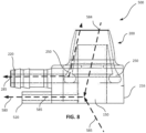
- a nasal cannula 500 includes a first connector 220 defining an air flow channel 221 that is in flow communication with circumferential cavity 250 in prong 200 and may include an additional connector 520 defining an airflow channel 521 that is in fluid communication with flow through bore 150.
- a base 216 provides structural support for prong 200, connector 220 and additional connector 520.
- additional connector 520 may be configured to connect air flow to a sensor, e.g. pressure sensor or air sampler configured to monitor parameters while a patient is breathing. Measurements may be made while air or gas is being delivered through channel 221 into circumferential cavity 250 optionally in synchronization with a breathing rhythm and may also be made while no air or gas is being delivered.
- a diameter of air flow channel 521 defined through additional connector 520 is smaller than air flow channel 221 defined through connector 220.
- prong 200 for a left nostril may include both connectors 220 and 520 and another prong 200 for a right nostril may only include connector 220.
- prong 200 for a left nostril may include both connectors 220 and 520 and another prong 200 for a right nostril may also include both connectors 220 and 520.
- Prongs 200 for both nostrils may be formed in a single base 215 as shown for example in FIGS. 1-3 .
- FIG. 8 is a side view of the other example nasal cannula with arrows indicating example airflow directions in accordance with some example embodiments of the present disclosure.
- air may be extracted from connector 520 for sensing.
- a vacuum may be applied to extract air from bore 150 (arrow 580).
- Sampled air may be air that a patient exhales (arrow 584) and may be air from the surrounding environment that a patient inhales (arrow 585).
- a sensor connected to connector 520 may sense parameters related to both inhalation and exhalation. In some example embodiments, sensing may be alternatively or additionally performed via connector 520.
- a nasal cannula 100 may be connected to tubing 400 based on attaching ends 401 to connectors 220.
- Tubing 400 typically includes a distal connector 450 connected to tube 400 at an end opposite an end at which nasal cannula 100 is connected.
- Distal connector 450 may be connected to one or more of a gas supply source 440 for delivering gas to the patient, a pressure sensor 430 configured to monitor pressure in nasal cavity during breathing, and a vacuum actuator 410, e.g. a pump for extracting air from the nasal cavity to a sampler 420 for sampling the air in the nasal cavity.
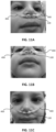
- example nasal cannula 100 may be sized to fit an infant. While the infant may receive air or gasses delivered to nasal cannula 100 via tubes 230 and connectors 220, the infant may also freely inhale and exhale air naturally (from the surrounding environment) through bore 150 in nasal cannula 100.
- Graph 300 is an example graph of actual nasal airflow recorded through nasal cannula 100.
- nasal cannula 100 may avoid end-distending pressure buildup and thereby the risk of gastrointestinal perforations.
Landscapes
- Health & Medical Sciences (AREA)
- Pulmonology (AREA)
- Emergency Medicine (AREA)
- Biomedical Technology (AREA)
- Engineering & Computer Science (AREA)
- Anesthesiology (AREA)
- Heart & Thoracic Surgery (AREA)
- Hematology (AREA)
- Life Sciences & Earth Sciences (AREA)
- Animal Behavior & Ethology (AREA)
- General Health & Medical Sciences (AREA)
- Public Health (AREA)
- Veterinary Medicine (AREA)
- Otolaryngology (AREA)
- Measurement Of The Respiration, Hearing Ability, Form, And Blood Characteristics Of Living Organisms (AREA)
Claims (13)
- Nasenkanüle (100), umfassend:einen Stutzen (200), der aus einer inneren zylindrischen Wand (210), die von einer äußeren zylindrischen Wand (205) umgeben ist, gebildet ist, und eine Basis (215), die die innere zylindrische Wand (210) mit der äußeren zylindrischen Wand (205) verbindet, wobei die innere zylindrische Wand (210), die äußere zylindrische Wand (205) und die Basis (215) zusammen einen Luftkanal (250) zwischen der inneren zylindrischen Wand (210) und der äußeren zylindrischen Wand (205) definieren, wobei die innere zylindrische Wand (210 ), die äußere zylindrische Wand (205) und der Luftkanal (250) dazwischen so ausgestaltet sind, dass sie innerhalb eines Nasenlochs aufgenommen werden können, und wobei die innere zylindrische Wand (210) eine Bohrung (150) definiert, durch die Luft frei strömen kann; undeinen Verbinder (220), der mit dem Luftkanal (250) in Fluidverbindung steht und so ausgestaltet ist, dass er eine Strömungsverbindung zwischen dem Luftkanal (250) und einer externen Vorrichtung bereitstellt, die mit dem Verbinder (220) verbunden ist.
- Nasenkanüle (100) nach Anspruch 1, wobei die innere zylindrische Wand (210) eine erste Höhe aufweist und wobei die äußere zylindrische Wand (205) eine zweite Höhe aufweist, und wobei die erste Höhe kleiner als die zweite Höhe ist.
- Nasenkanüle (100) nach Anspruch 1 oder Anspruch 2, wobei die äußere zylindrische Wand (205) eine Kegelstumpfform aufweist.
- Nasenkanüle (100) nach einem der Ansprüche 1-3, wobei die innere zylindrische Wand (210) einen ersten Durchmesser aufweist und wobei die äußere zylindrische Wand (205) einen zweiten Durchmesser an ihrem distalen Ende in Bezug auf die Basis (215) aufweist, und wobei ein Verhältnis des ersten Durchmessers zu dem zweiten Durchmesser 0,8-1,0 beträgt.
- Nasenkanüle (100) nach einem der Ansprüche 1-4, wobei sich eine Breite des Luftkanals (250) distal zur Basis (215) verjüngt.
- Nasenkanüle (100) nach einem der Ansprüche 1-5, wobei der Verbinder (220) mittels eines in der äußeren zylindrischen Wand gebildeten Ports mit dem Luftkanal (250) verbunden ist.
- Nasenkanüle (100) nach einem der Ansprüche 1-6, wobei die Basis (215) so ausgestaltet ist, dass sie den Stutzen (200) und den Verbinder (220) strukturell trägt, und wobei sich die durch die innere zylindrische Wand (210) definierte Bohrung (150) durch die Basis (215) erstreckt.
- Nasenkanüle (100) nach einem der Ansprüche 1-7, wobei die innere zylindrische Wand (210) so ausgestaltet ist, dass sie flexibel ist, und bei fehlendem Strömungsdruck im Luftkanal (250) in Richtung der äußeren zylindrischen Wand (205) zusammenfällt.
- Nasenkanüle (100) nach einem der Ansprüche 1-8, wobei die externe Vorrichtung eine Quelle für Druckgas ist, und wobei der Luftkanal (250) so ausgestaltet ist, dass er Gas von der externen Vorrichtung mittels des Verbinders (220) aufnimmt und das Gas durch eine Öffnung zwischen der inneren zylindrischen Wand und der äußeren zylindrischen Wand ausstößt.
- Nasenkanüle (100) nach einem der Ansprüche 1-9, wobei der Stutzen (200) so ausgestaltet ist, dass er eine Strömungsverbindung von der Öffnung zwischen der inneren zylindrischen Wand und der äußeren zylindrischen Wand zur externen Vorrichtung basierend auf dem Anlegen eines Vakuums durch den Verbinder (220) hindurch bereitstellt.
- Nasenkanüle (100) nach einem der Ansprüche 1-10, die einen zweiten Verbinder (520) umfasst, der mit einem Port in der inneren zylindrischen Wand verbunden ist, wobei der zweite Verbinder (520) so ausgestaltet ist, dass er eine Strömungsverbindung zwischen der Bohrung (150) und einen Sensor zum Abfühlen eines Atemparameters bereitstellt.
- Nasenkanüle (100) nach einem der Ansprüche 1-11, die ein Paar von Stutzen (200) umfasst, wobei die Basis (215) das Paar verbindet.
- Nasenkanüle (100) nach Anspruch 12, die ein Paar von Verbindern (220) umfasst, wobei jeder Verbinder (220) des Paars mit dem Luftkanal (250) eines des Paares der Stutzen (200) in Fluidverbindung steht.
Applications Claiming Priority (3)
| Application Number | Priority Date | Filing Date | Title |
|---|---|---|---|
| US201862664176P | 2018-04-29 | 2018-04-29 | |
| US201862674648P | 2018-05-22 | 2018-05-22 | |
| PCT/IL2019/050470 WO2019211834A1 (en) | 2018-04-29 | 2019-04-28 | Non-obstructive nasal cannula |
Publications (2)
| Publication Number | Publication Date |
|---|---|
| EP3787723A1 EP3787723A1 (de) | 2021-03-10 |
| EP3787723B1 true EP3787723B1 (de) | 2024-02-28 |
Family
ID=66542480
Family Applications (1)
| Application Number | Title | Priority Date | Filing Date |
|---|---|---|---|
| EP19724259.7A Active EP3787723B1 (de) | 2018-04-29 | 2019-04-28 | Nichtobstruktive nasenkanüle |
Country Status (3)
| Country | Link |
|---|---|
| US (1) | US20210046271A1 (de) |
| EP (1) | EP3787723B1 (de) |
| WO (1) | WO2019211834A1 (de) |
Families Citing this family (3)
| Publication number | Priority date | Publication date | Assignee | Title |
|---|---|---|---|---|
| WO2018042355A1 (en) * | 2016-08-31 | 2018-03-08 | Fisher & Paykel Healthcare Limited | A patient interface, system and method |
| CN111330130A (zh) * | 2020-03-04 | 2020-06-26 | 深圳市量子氢生物技术有限公司 | 分腔式鼻吸管 |
| US20220339378A1 (en) * | 2021-04-21 | 2022-10-27 | Hill-Rom Services Pte. Ltd. | Accurate pressure measurement with non-invasive ventilation nasal pillows |
Family Cites Families (13)
| Publication number | Priority date | Publication date | Assignee | Title |
|---|---|---|---|---|
| US5099836A (en) * | 1987-10-05 | 1992-03-31 | Hudson Respiratory Care Inc. | Intermittent oxygen delivery system and cannula |
| US20050121033A1 (en) * | 1998-02-25 | 2005-06-09 | Ric Investments, Llc. | Respiratory monitoring during gas delivery |
| FR2827778B1 (fr) * | 2001-07-30 | 2004-05-28 | Vygon | Appareil nasal d'assistance respiratoire |
| US6679265B2 (en) * | 2001-10-25 | 2004-01-20 | Worldwide Medical Technologies | Nasal cannula |
| US7114497B2 (en) * | 2003-07-18 | 2006-10-03 | Acoba, Llc | Method and system of individually controlling airway pressure of a patient's nares |
| US8333199B2 (en) * | 2005-09-12 | 2012-12-18 | Mergenet Medical, Inc. | High flow therapy artificial airway interfaces and related methods |
| US20080047559A1 (en) * | 2006-08-22 | 2008-02-28 | Romeo Fiori | Nasal positive pressure ventilation apparatus and method |
| US8631799B2 (en) * | 2008-01-25 | 2014-01-21 | Salter Labs | Respiratory therapy system including a nasal cannula assembly |
| US20110006763A1 (en) * | 2009-07-07 | 2011-01-13 | Anthonius Bakker | Hall effect current sensor system and associated flip-chip packaging |
| MY168202A (en) * | 2010-04-14 | 2018-10-15 | Ngah Chai Leow | Nasal cannula for carbon dioxide sampling |
| EP2931347B1 (de) * | 2012-12-11 | 2018-08-08 | Koninklijke Philips N.V. | Nasenkanülensystem |
| US9517318B2 (en) * | 2013-06-28 | 2016-12-13 | L'Air Liquide, Société Anonyme pour l'Etude et l'Exploitation des Procédés Georges Claude | Method of delivering medical gases via a nasal cannula assembly with flow control passage communicating with a deformable reservoir |
| US10322252B2 (en) * | 2015-07-10 | 2019-06-18 | Darin B Atherton | Ergonomic nasal cannula |
-
2019
- 2019-04-28 EP EP19724259.7A patent/EP3787723B1/de active Active
- 2019-04-28 WO PCT/IL2019/050470 patent/WO2019211834A1/en not_active Ceased
-
2020
- 2020-10-29 US US17/083,493 patent/US20210046271A1/en not_active Abandoned
Also Published As
| Publication number | Publication date |
|---|---|
| WO2019211834A1 (en) | 2019-11-07 |
| EP3787723A1 (de) | 2021-03-10 |
| US20210046271A1 (en) | 2021-02-18 |
Similar Documents
| Publication | Publication Date | Title |
|---|---|---|
| CN102355920B (zh) | 射流通气导管 | |
| US10342456B2 (en) | Apparatus, arrangement and method for analyzing breathing gas flowing along breathing tubing for subject breathing | |
| US8925549B2 (en) | Flow control adapter for performing spirometry and pulmonary function testing | |
| US9138556B2 (en) | Device for respiratory assistance, and measurement system comprising such a device | |
| EP3787723B1 (de) | Nichtobstruktive nasenkanüle | |
| JP6734268B2 (ja) | 呼吸補助機器、鼻用装置、および呼吸補助マスク | |
| EP3294394B1 (de) | Flüssigkeitsentfernung bei einer patientenschnittstellenanordnung | |
| KR20220092496A (ko) | 호흡기 치료 시스템 및 장치 | |
| AU2010351102B2 (en) | Nasal cannula for carbon dioxide sampling | |
| CN105848702A (zh) | 用于呼吸系统的过滤热湿交换装置 | |
| CN103384542A (zh) | 用于新生儿复苏和初始呼吸支持的系统和装置 | |
| TW202300190A (zh) | 患者介面 | |
| EP3235535B1 (de) | Vorrichtung für nasale high-flow-therapie | |
| US11779724B2 (en) | Respiration sensor attachment device | |
| JP2024503250A (ja) | 一体化された酸素送達を有するベンチレータシステムおよび関連付けられたデバイスおよび方法 | |
| EP2890438B1 (de) | Atemhilfevorrichtung, nasale vorrichtung und atemhilfemaske | |
| CN110785124A (zh) | 用于感测呼吸参数的非侵入式装置和方法 | |
| CN107427654B (zh) | 流动构件 | |
| EP3468465B1 (de) | Gassensorkit und im gesicht tragbare vorrichtung | |
| CN217472534U (zh) | 一种可监测呼末的吸氧面罩 | |
| TWM465917U (zh) | 人工呼吸器 | |
| AU2021221742A1 (en) | Patent interface gas sampling |
Legal Events
| Date | Code | Title | Description |
|---|---|---|---|
| STAA | Information on the status of an ep patent application or granted ep patent |
Free format text: STATUS: UNKNOWN |
|
| STAA | Information on the status of an ep patent application or granted ep patent |
Free format text: STATUS: THE INTERNATIONAL PUBLICATION HAS BEEN MADE |
|
| PUAI | Public reference made under article 153(3) epc to a published international application that has entered the european phase |
Free format text: ORIGINAL CODE: 0009012 |
|
| STAA | Information on the status of an ep patent application or granted ep patent |
Free format text: STATUS: REQUEST FOR EXAMINATION WAS MADE |
|
| 17P | Request for examination filed |
Effective date: 20201127 |
|
| AK | Designated contracting states |
Kind code of ref document: A1 Designated state(s): AL AT BE BG CH CY CZ DE DK EE ES FI FR GB GR HR HU IE IS IT LI LT LU LV MC MK MT NL NO PL PT RO RS SE SI SK SM TR |
|
| AX | Request for extension of the european patent |
Extension state: BA ME |
|
| DAV | Request for validation of the european patent (deleted) | ||
| DAX | Request for extension of the european patent (deleted) | ||
| REG | Reference to a national code |
Ref country code: HK Ref legal event code: DE Ref document number: 40049482 Country of ref document: HK |
|
| RAP1 | Party data changed (applicant data changed or rights of an application transferred) |
Owner name: SOBEL, NOAM |
|
| STAA | Information on the status of an ep patent application or granted ep patent |
Free format text: STATUS: EXAMINATION IS IN PROGRESS |
|
| 17Q | First examination report despatched |
Effective date: 20230113 |
|
| GRAP | Despatch of communication of intention to grant a patent |
Free format text: ORIGINAL CODE: EPIDOSNIGR1 |
|
| STAA | Information on the status of an ep patent application or granted ep patent |
Free format text: STATUS: GRANT OF PATENT IS INTENDED |
|
| INTG | Intention to grant announced |
Effective date: 20230921 |
|
| GRAS | Grant fee paid |
Free format text: ORIGINAL CODE: EPIDOSNIGR3 |
|
| GRAA | (expected) grant |
Free format text: ORIGINAL CODE: 0009210 |
|
| STAA | Information on the status of an ep patent application or granted ep patent |
Free format text: STATUS: THE PATENT HAS BEEN GRANTED |
|
| AK | Designated contracting states |
Kind code of ref document: B1 Designated state(s): AL AT BE BG CH CY CZ DE DK EE ES FI FR GB GR HR HU IE IS IT LI LT LU LV MC MK MT NL NO PL PT RO RS SE SI SK SM TR |
|
| REG | Reference to a national code |
Ref country code: GB Ref legal event code: FG4D |
|
| REG | Reference to a national code |
Ref country code: CH Ref legal event code: EP |
|
| REG | Reference to a national code |
Ref country code: DE Ref legal event code: R096 Ref document number: 602019047304 Country of ref document: DE |
|
| REG | Reference to a national code |
Ref country code: IE Ref legal event code: FG4D |
|
| REG | Reference to a national code |
Ref country code: LT Ref legal event code: MG9D |
|
| PG25 | Lapsed in a contracting state [announced via postgrant information from national office to epo] |
Ref country code: IS Free format text: LAPSE BECAUSE OF FAILURE TO SUBMIT A TRANSLATION OF THE DESCRIPTION OR TO PAY THE FEE WITHIN THE PRESCRIBED TIME-LIMIT Effective date: 20240628 |
|
| REG | Reference to a national code |
Ref country code: NL Ref legal event code: MP Effective date: 20240228 |
|
| PG25 | Lapsed in a contracting state [announced via postgrant information from national office to epo] |
Ref country code: LT Free format text: LAPSE BECAUSE OF FAILURE TO SUBMIT A TRANSLATION OF THE DESCRIPTION OR TO PAY THE FEE WITHIN THE PRESCRIBED TIME-LIMIT Effective date: 20240228 |
|
| PG25 | Lapsed in a contracting state [announced via postgrant information from national office to epo] |
Ref country code: GR Free format text: LAPSE BECAUSE OF FAILURE TO SUBMIT A TRANSLATION OF THE DESCRIPTION OR TO PAY THE FEE WITHIN THE PRESCRIBED TIME-LIMIT Effective date: 20240529 |
|
| PG25 | Lapsed in a contracting state [announced via postgrant information from national office to epo] |
Ref country code: NL Free format text: LAPSE BECAUSE OF FAILURE TO SUBMIT A TRANSLATION OF THE DESCRIPTION OR TO PAY THE FEE WITHIN THE PRESCRIBED TIME-LIMIT Effective date: 20240228 Ref country code: HR Free format text: LAPSE BECAUSE OF FAILURE TO SUBMIT A TRANSLATION OF THE DESCRIPTION OR TO PAY THE FEE WITHIN THE PRESCRIBED TIME-LIMIT Effective date: 20240228 Ref country code: RS Free format text: LAPSE BECAUSE OF FAILURE TO SUBMIT A TRANSLATION OF THE DESCRIPTION OR TO PAY THE FEE WITHIN THE PRESCRIBED TIME-LIMIT Effective date: 20240528 |
|
| PG25 | Lapsed in a contracting state [announced via postgrant information from national office to epo] |
Ref country code: ES Free format text: LAPSE BECAUSE OF FAILURE TO SUBMIT A TRANSLATION OF THE DESCRIPTION OR TO PAY THE FEE WITHIN THE PRESCRIBED TIME-LIMIT Effective date: 20240228 |
|
| PG25 | Lapsed in a contracting state [announced via postgrant information from national office to epo] |
Ref country code: RS Free format text: LAPSE BECAUSE OF FAILURE TO SUBMIT A TRANSLATION OF THE DESCRIPTION OR TO PAY THE FEE WITHIN THE PRESCRIBED TIME-LIMIT Effective date: 20240528 Ref country code: NO Free format text: LAPSE BECAUSE OF FAILURE TO SUBMIT A TRANSLATION OF THE DESCRIPTION OR TO PAY THE FEE WITHIN THE PRESCRIBED TIME-LIMIT Effective date: 20240528 Ref country code: NL Free format text: LAPSE BECAUSE OF FAILURE TO SUBMIT A TRANSLATION OF THE DESCRIPTION OR TO PAY THE FEE WITHIN THE PRESCRIBED TIME-LIMIT Effective date: 20240228 Ref country code: LT Free format text: LAPSE BECAUSE OF FAILURE TO SUBMIT A TRANSLATION OF THE DESCRIPTION OR TO PAY THE FEE WITHIN THE PRESCRIBED TIME-LIMIT Effective date: 20240228 Ref country code: IS Free format text: LAPSE BECAUSE OF FAILURE TO SUBMIT A TRANSLATION OF THE DESCRIPTION OR TO PAY THE FEE WITHIN THE PRESCRIBED TIME-LIMIT Effective date: 20240628 Ref country code: HR Free format text: LAPSE BECAUSE OF FAILURE TO SUBMIT A TRANSLATION OF THE DESCRIPTION OR TO PAY THE FEE WITHIN THE PRESCRIBED TIME-LIMIT Effective date: 20240228 Ref country code: GR Free format text: LAPSE BECAUSE OF FAILURE TO SUBMIT A TRANSLATION OF THE DESCRIPTION OR TO PAY THE FEE WITHIN THE PRESCRIBED TIME-LIMIT Effective date: 20240529 Ref country code: FI Free format text: LAPSE BECAUSE OF FAILURE TO SUBMIT A TRANSLATION OF THE DESCRIPTION OR TO PAY THE FEE WITHIN THE PRESCRIBED TIME-LIMIT Effective date: 20240228 Ref country code: ES Free format text: LAPSE BECAUSE OF FAILURE TO SUBMIT A TRANSLATION OF THE DESCRIPTION OR TO PAY THE FEE WITHIN THE PRESCRIBED TIME-LIMIT Effective date: 20240228 Ref country code: BG Free format text: LAPSE BECAUSE OF FAILURE TO SUBMIT A TRANSLATION OF THE DESCRIPTION OR TO PAY THE FEE WITHIN THE PRESCRIBED TIME-LIMIT Effective date: 20240228 |
|
| PG25 | Lapsed in a contracting state [announced via postgrant information from national office to epo] |
Ref country code: PT Free format text: LAPSE BECAUSE OF FAILURE TO SUBMIT A TRANSLATION OF THE DESCRIPTION OR TO PAY THE FEE WITHIN THE PRESCRIBED TIME-LIMIT Effective date: 20240628 Ref country code: PL Free format text: LAPSE BECAUSE OF FAILURE TO SUBMIT A TRANSLATION OF THE DESCRIPTION OR TO PAY THE FEE WITHIN THE PRESCRIBED TIME-LIMIT Effective date: 20240228 |
|
| REG | Reference to a national code |
Ref country code: AT Ref legal event code: MK05 Ref document number: 1660658 Country of ref document: AT Kind code of ref document: T Effective date: 20240228 |
|
| PG25 | Lapsed in a contracting state [announced via postgrant information from national office to epo] |
Ref country code: SE Free format text: LAPSE BECAUSE OF FAILURE TO SUBMIT A TRANSLATION OF THE DESCRIPTION OR TO PAY THE FEE WITHIN THE PRESCRIBED TIME-LIMIT Effective date: 20240228 Ref country code: PT Free format text: LAPSE BECAUSE OF FAILURE TO SUBMIT A TRANSLATION OF THE DESCRIPTION OR TO PAY THE FEE WITHIN THE PRESCRIBED TIME-LIMIT Effective date: 20240628 Ref country code: PL Free format text: LAPSE BECAUSE OF FAILURE TO SUBMIT A TRANSLATION OF THE DESCRIPTION OR TO PAY THE FEE WITHIN THE PRESCRIBED TIME-LIMIT Effective date: 20240228 Ref country code: LV Free format text: LAPSE BECAUSE OF FAILURE TO SUBMIT A TRANSLATION OF THE DESCRIPTION OR TO PAY THE FEE WITHIN THE PRESCRIBED TIME-LIMIT Effective date: 20240228 |
|
| PG25 | Lapsed in a contracting state [announced via postgrant information from national office to epo] |
Ref country code: DK Free format text: LAPSE BECAUSE OF FAILURE TO SUBMIT A TRANSLATION OF THE DESCRIPTION OR TO PAY THE FEE WITHIN THE PRESCRIBED TIME-LIMIT Effective date: 20240228 |
|
| PG25 | Lapsed in a contracting state [announced via postgrant information from national office to epo] |
Ref country code: SM Free format text: LAPSE BECAUSE OF FAILURE TO SUBMIT A TRANSLATION OF THE DESCRIPTION OR TO PAY THE FEE WITHIN THE PRESCRIBED TIME-LIMIT Effective date: 20240228 |
|
| PG25 | Lapsed in a contracting state [announced via postgrant information from national office to epo] |
Ref country code: CZ Free format text: LAPSE BECAUSE OF FAILURE TO SUBMIT A TRANSLATION OF THE DESCRIPTION OR TO PAY THE FEE WITHIN THE PRESCRIBED TIME-LIMIT Effective date: 20240228 Ref country code: EE Free format text: LAPSE BECAUSE OF FAILURE TO SUBMIT A TRANSLATION OF THE DESCRIPTION OR TO PAY THE FEE WITHIN THE PRESCRIBED TIME-LIMIT Effective date: 20240228 |
|
| PG25 | Lapsed in a contracting state [announced via postgrant information from national office to epo] |
Ref country code: AT Free format text: LAPSE BECAUSE OF FAILURE TO SUBMIT A TRANSLATION OF THE DESCRIPTION OR TO PAY THE FEE WITHIN THE PRESCRIBED TIME-LIMIT Effective date: 20240228 |
|
| PG25 | Lapsed in a contracting state [announced via postgrant information from national office to epo] |
Ref country code: SK Free format text: LAPSE BECAUSE OF FAILURE TO SUBMIT A TRANSLATION OF THE DESCRIPTION OR TO PAY THE FEE WITHIN THE PRESCRIBED TIME-LIMIT Effective date: 20240228 |
|
| PG25 | Lapsed in a contracting state [announced via postgrant information from national office to epo] |
Ref country code: SM Free format text: LAPSE BECAUSE OF FAILURE TO SUBMIT A TRANSLATION OF THE DESCRIPTION OR TO PAY THE FEE WITHIN THE PRESCRIBED TIME-LIMIT Effective date: 20240228 Ref country code: SK Free format text: LAPSE BECAUSE OF FAILURE TO SUBMIT A TRANSLATION OF THE DESCRIPTION OR TO PAY THE FEE WITHIN THE PRESCRIBED TIME-LIMIT Effective date: 20240228 Ref country code: RO Free format text: LAPSE BECAUSE OF FAILURE TO SUBMIT A TRANSLATION OF THE DESCRIPTION OR TO PAY THE FEE WITHIN THE PRESCRIBED TIME-LIMIT Effective date: 20240228 Ref country code: EE Free format text: LAPSE BECAUSE OF FAILURE TO SUBMIT A TRANSLATION OF THE DESCRIPTION OR TO PAY THE FEE WITHIN THE PRESCRIBED TIME-LIMIT Effective date: 20240228 Ref country code: DK Free format text: LAPSE BECAUSE OF FAILURE TO SUBMIT A TRANSLATION OF THE DESCRIPTION OR TO PAY THE FEE WITHIN THE PRESCRIBED TIME-LIMIT Effective date: 20240228 Ref country code: CZ Free format text: LAPSE BECAUSE OF FAILURE TO SUBMIT A TRANSLATION OF THE DESCRIPTION OR TO PAY THE FEE WITHIN THE PRESCRIBED TIME-LIMIT Effective date: 20240228 Ref country code: AT Free format text: LAPSE BECAUSE OF FAILURE TO SUBMIT A TRANSLATION OF THE DESCRIPTION OR TO PAY THE FEE WITHIN THE PRESCRIBED TIME-LIMIT Effective date: 20240228 |
|
| REG | Reference to a national code |
Ref country code: DE Ref legal event code: R119 Ref document number: 602019047304 Country of ref document: DE |
|
| PG25 | Lapsed in a contracting state [announced via postgrant information from national office to epo] |
Ref country code: MC Free format text: LAPSE BECAUSE OF FAILURE TO SUBMIT A TRANSLATION OF THE DESCRIPTION OR TO PAY THE FEE WITHIN THE PRESCRIBED TIME-LIMIT Effective date: 20240228 |
|
| PG25 | Lapsed in a contracting state [announced via postgrant information from national office to epo] |
Ref country code: MC Free format text: LAPSE BECAUSE OF FAILURE TO SUBMIT A TRANSLATION OF THE DESCRIPTION OR TO PAY THE FEE WITHIN THE PRESCRIBED TIME-LIMIT Effective date: 20240228 |
|
| REG | Reference to a national code |
Ref country code: CH Ref legal event code: PL |
|
| PG25 | Lapsed in a contracting state [announced via postgrant information from national office to epo] |
Ref country code: IT Free format text: LAPSE BECAUSE OF FAILURE TO SUBMIT A TRANSLATION OF THE DESCRIPTION OR TO PAY THE FEE WITHIN THE PRESCRIBED TIME-LIMIT Effective date: 20240228 |
|
| PG25 | Lapsed in a contracting state [announced via postgrant information from national office to epo] |
Ref country code: LU Free format text: LAPSE BECAUSE OF NON-PAYMENT OF DUE FEES Effective date: 20240428 |
|
| REG | Reference to a national code |
Ref country code: BE Ref legal event code: MM Effective date: 20240430 |
|
| PG25 | Lapsed in a contracting state [announced via postgrant information from national office to epo] |
Ref country code: LU Free format text: LAPSE BECAUSE OF NON-PAYMENT OF DUE FEES Effective date: 20240428 Ref country code: IT Free format text: LAPSE BECAUSE OF FAILURE TO SUBMIT A TRANSLATION OF THE DESCRIPTION OR TO PAY THE FEE WITHIN THE PRESCRIBED TIME-LIMIT Effective date: 20240228 |
|
| PLBE | No opposition filed within time limit |
Free format text: ORIGINAL CODE: 0009261 |
|
| STAA | Information on the status of an ep patent application or granted ep patent |
Free format text: STATUS: NO OPPOSITION FILED WITHIN TIME LIMIT |
|
| PG25 | Lapsed in a contracting state [announced via postgrant information from national office to epo] |
Ref country code: DE Free format text: LAPSE BECAUSE OF NON-PAYMENT OF DUE FEES Effective date: 20241105 |
|
| PG25 | Lapsed in a contracting state [announced via postgrant information from national office to epo] |
Ref country code: BE Free format text: LAPSE BECAUSE OF NON-PAYMENT OF DUE FEES Effective date: 20240430 |
|
| PG25 | Lapsed in a contracting state [announced via postgrant information from national office to epo] |
Ref country code: FR Free format text: LAPSE BECAUSE OF NON-PAYMENT OF DUE FEES Effective date: 20240428 |
|
| GBPC | Gb: european patent ceased through non-payment of renewal fee |
Effective date: 20240528 |
|
| PG25 | Lapsed in a contracting state [announced via postgrant information from national office to epo] |
Ref country code: FR Free format text: LAPSE BECAUSE OF NON-PAYMENT OF DUE FEES Effective date: 20240428 Ref country code: DE Free format text: LAPSE BECAUSE OF NON-PAYMENT OF DUE FEES Effective date: 20241105 Ref country code: BE Free format text: LAPSE BECAUSE OF NON-PAYMENT OF DUE FEES Effective date: 20240430 Ref country code: CH Free format text: LAPSE BECAUSE OF NON-PAYMENT OF DUE FEES Effective date: 20240430 |
|
| 26N | No opposition filed |
Effective date: 20241129 |
|
| PG25 | Lapsed in a contracting state [announced via postgrant information from national office to epo] |
Ref country code: IE Free format text: LAPSE BECAUSE OF NON-PAYMENT OF DUE FEES Effective date: 20240428 |
|
| PG25 | Lapsed in a contracting state [announced via postgrant information from national office to epo] |
Ref country code: SI Free format text: LAPSE BECAUSE OF FAILURE TO SUBMIT A TRANSLATION OF THE DESCRIPTION OR TO PAY THE FEE WITHIN THE PRESCRIBED TIME-LIMIT Effective date: 20240228 |
|
| PG25 | Lapsed in a contracting state [announced via postgrant information from national office to epo] |
Ref country code: GB Free format text: LAPSE BECAUSE OF NON-PAYMENT OF DUE FEES Effective date: 20240528 |
|
| PG25 | Lapsed in a contracting state [announced via postgrant information from national office to epo] |
Ref country code: CY Free format text: LAPSE BECAUSE OF FAILURE TO SUBMIT A TRANSLATION OF THE DESCRIPTION OR TO PAY THE FEE WITHIN THE PRESCRIBED TIME-LIMIT; INVALID AB INITIO Effective date: 20190428 |
|
| PG25 | Lapsed in a contracting state [announced via postgrant information from national office to epo] |
Ref country code: HU Free format text: LAPSE BECAUSE OF FAILURE TO SUBMIT A TRANSLATION OF THE DESCRIPTION OR TO PAY THE FEE WITHIN THE PRESCRIBED TIME-LIMIT; INVALID AB INITIO Effective date: 20190428 |