EP3787795B1 - Ventilloser fluidischer schalt-flowchip und verwendungen davon - Google Patents
Ventilloser fluidischer schalt-flowchip und verwendungen davon Download PDFInfo
- Publication number
- EP3787795B1 EP3787795B1 EP19796922.3A EP19796922A EP3787795B1 EP 3787795 B1 EP3787795 B1 EP 3787795B1 EP 19796922 A EP19796922 A EP 19796922A EP 3787795 B1 EP3787795 B1 EP 3787795B1
- Authority
- EP
- European Patent Office
- Prior art keywords
- cavity
- pressure
- channel
- fluid
- destination
- Prior art date
- Legal status (The legal status is an assumption and is not a legal conclusion. Google has not performed a legal analysis and makes no representation as to the accuracy of the status listed.)
- Active
Links
Images













Classifications
-
- B—PERFORMING OPERATIONS; TRANSPORTING
- B01—PHYSICAL OR CHEMICAL PROCESSES OR APPARATUS IN GENERAL
- B01L—CHEMICAL OR PHYSICAL LABORATORY APPARATUS FOR GENERAL USE
- B01L3/00—Containers or dishes for laboratory use, e.g. laboratory glassware; Droppers
- B01L3/50—Containers for the purpose of retaining a material to be analysed, e.g. test tubes
- B01L3/502—Containers for the purpose of retaining a material to be analysed, e.g. test tubes with fluid transport, e.g. in multi-compartment structures
- B01L3/5027—Containers for the purpose of retaining a material to be analysed, e.g. test tubes with fluid transport, e.g. in multi-compartment structures by integrated microfluidic structures, i.e. dimensions of channels and chambers are such that surface tension forces are important, e.g. lab-on-a-chip
- B01L3/50273—Containers for the purpose of retaining a material to be analysed, e.g. test tubes with fluid transport, e.g. in multi-compartment structures by integrated microfluidic structures, i.e. dimensions of channels and chambers are such that surface tension forces are important, e.g. lab-on-a-chip characterised by the means or forces applied to move the fluids
-
- B—PERFORMING OPERATIONS; TRANSPORTING
- B01—PHYSICAL OR CHEMICAL PROCESSES OR APPARATUS IN GENERAL
- B01L—CHEMICAL OR PHYSICAL LABORATORY APPARATUS FOR GENERAL USE
- B01L3/00—Containers or dishes for laboratory use, e.g. laboratory glassware; Droppers
- B01L3/50—Containers for the purpose of retaining a material to be analysed, e.g. test tubes
- B01L3/502—Containers for the purpose of retaining a material to be analysed, e.g. test tubes with fluid transport, e.g. in multi-compartment structures
- B01L3/5027—Containers for the purpose of retaining a material to be analysed, e.g. test tubes with fluid transport, e.g. in multi-compartment structures by integrated microfluidic structures, i.e. dimensions of channels and chambers are such that surface tension forces are important, e.g. lab-on-a-chip
- B01L3/502738—Containers for the purpose of retaining a material to be analysed, e.g. test tubes with fluid transport, e.g. in multi-compartment structures by integrated microfluidic structures, i.e. dimensions of channels and chambers are such that surface tension forces are important, e.g. lab-on-a-chip characterised by integrated valves
-
- B—PERFORMING OPERATIONS; TRANSPORTING
- B01—PHYSICAL OR CHEMICAL PROCESSES OR APPARATUS IN GENERAL
- B01L—CHEMICAL OR PHYSICAL LABORATORY APPARATUS FOR GENERAL USE
- B01L3/00—Containers or dishes for laboratory use, e.g. laboratory glassware; Droppers
- B01L3/50—Containers for the purpose of retaining a material to be analysed, e.g. test tubes
- B01L3/502—Containers for the purpose of retaining a material to be analysed, e.g. test tubes with fluid transport, e.g. in multi-compartment structures
- B01L3/5027—Containers for the purpose of retaining a material to be analysed, e.g. test tubes with fluid transport, e.g. in multi-compartment structures by integrated microfluidic structures, i.e. dimensions of channels and chambers are such that surface tension forces are important, e.g. lab-on-a-chip
- B01L3/502746—Containers for the purpose of retaining a material to be analysed, e.g. test tubes with fluid transport, e.g. in multi-compartment structures by integrated microfluidic structures, i.e. dimensions of channels and chambers are such that surface tension forces are important, e.g. lab-on-a-chip characterised by the means for controlling flow resistance, e.g. flow controllers, baffles or throttle valves
-
- B—PERFORMING OPERATIONS; TRANSPORTING
- B01—PHYSICAL OR CHEMICAL PROCESSES OR APPARATUS IN GENERAL
- B01L—CHEMICAL OR PHYSICAL LABORATORY APPARATUS FOR GENERAL USE
- B01L3/00—Containers or dishes for laboratory use, e.g. laboratory glassware; Droppers
- B01L3/50—Containers for the purpose of retaining a material to be analysed, e.g. test tubes
- B01L3/502—Containers for the purpose of retaining a material to be analysed, e.g. test tubes with fluid transport, e.g. in multi-compartment structures
- B01L3/5027—Containers for the purpose of retaining a material to be analysed, e.g. test tubes with fluid transport, e.g. in multi-compartment structures by integrated microfluidic structures, i.e. dimensions of channels and chambers are such that surface tension forces are important, e.g. lab-on-a-chip
- B01L3/502753—Containers for the purpose of retaining a material to be analysed, e.g. test tubes with fluid transport, e.g. in multi-compartment structures by integrated microfluidic structures, i.e. dimensions of channels and chambers are such that surface tension forces are important, e.g. lab-on-a-chip characterised by bulk separation arrangements on lab-on-a-chip devices, e.g. for filtration or centrifugation
-
- B—PERFORMING OPERATIONS; TRANSPORTING
- B01—PHYSICAL OR CHEMICAL PROCESSES OR APPARATUS IN GENERAL
- B01L—CHEMICAL OR PHYSICAL LABORATORY APPARATUS FOR GENERAL USE
- B01L3/00—Containers or dishes for laboratory use, e.g. laboratory glassware; Droppers
- B01L3/50—Containers for the purpose of retaining a material to be analysed, e.g. test tubes
- B01L3/502—Containers for the purpose of retaining a material to be analysed, e.g. test tubes with fluid transport, e.g. in multi-compartment structures
- B01L3/5027—Containers for the purpose of retaining a material to be analysed, e.g. test tubes with fluid transport, e.g. in multi-compartment structures by integrated microfluidic structures, i.e. dimensions of channels and chambers are such that surface tension forces are important, e.g. lab-on-a-chip
- B01L3/502761—Containers for the purpose of retaining a material to be analysed, e.g. test tubes with fluid transport, e.g. in multi-compartment structures by integrated microfluidic structures, i.e. dimensions of channels and chambers are such that surface tension forces are important, e.g. lab-on-a-chip specially adapted for handling suspended solids or molecules independently from the bulk fluid flow, e.g. for trapping or sorting beads or physically stretching molecules
-
- B—PERFORMING OPERATIONS; TRANSPORTING
- B01—PHYSICAL OR CHEMICAL PROCESSES OR APPARATUS IN GENERAL
- B01L—CHEMICAL OR PHYSICAL LABORATORY APPARATUS FOR GENERAL USE
- B01L3/00—Containers or dishes for laboratory use, e.g. laboratory glassware; Droppers
- B01L3/56—Labware specially adapted for transferring fluids
- B01L3/567—Valves, taps or stop-cocks
-
- G—PHYSICS
- G01—MEASURING; TESTING
- G01N—INVESTIGATING OR ANALYSING MATERIALS BY DETERMINING THEIR CHEMICAL OR PHYSICAL PROPERTIES
- G01N33/00—Investigating or analysing materials by specific methods not covered by groups G01N1/00 - G01N31/00
- G01N33/48—Biological material, e.g. blood, urine; Haemocytometers
- G01N33/50—Chemical analysis of biological material, e.g. blood, urine; Testing involving biospecific ligand binding methods; Immunological testing
- G01N33/53—Immunoassay; Biospecific binding assay; Materials therefor
- G01N33/5302—Apparatus specially adapted for immunological test procedures
- G01N33/5304—Reaction vessels, e.g. agglutination plates
-
- B—PERFORMING OPERATIONS; TRANSPORTING
- B01—PHYSICAL OR CHEMICAL PROCESSES OR APPARATUS IN GENERAL
- B01L—CHEMICAL OR PHYSICAL LABORATORY APPARATUS FOR GENERAL USE
- B01L2200/00—Solutions for specific problems relating to chemical or physical laboratory apparatus
- B01L2200/02—Adapting objects or devices to another
- B01L2200/026—Fluid interfacing between devices or objects, e.g. connectors, inlet details
- B01L2200/027—Fluid interfacing between devices or objects, e.g. connectors, inlet details for microfluidic devices
-
- B—PERFORMING OPERATIONS; TRANSPORTING
- B01—PHYSICAL OR CHEMICAL PROCESSES OR APPARATUS IN GENERAL
- B01L—CHEMICAL OR PHYSICAL LABORATORY APPARATUS FOR GENERAL USE
- B01L2200/00—Solutions for specific problems relating to chemical or physical laboratory apparatus
- B01L2200/06—Fluid handling related problems
- B01L2200/0647—Handling flowable solids, e.g. microscopic beads, cells, particles
-
- B—PERFORMING OPERATIONS; TRANSPORTING
- B01—PHYSICAL OR CHEMICAL PROCESSES OR APPARATUS IN GENERAL
- B01L—CHEMICAL OR PHYSICAL LABORATORY APPARATUS FOR GENERAL USE
- B01L2200/00—Solutions for specific problems relating to chemical or physical laboratory apparatus
- B01L2200/06—Fluid handling related problems
- B01L2200/0684—Venting, avoiding backpressure, avoid gas bubbles
-
- B—PERFORMING OPERATIONS; TRANSPORTING
- B01—PHYSICAL OR CHEMICAL PROCESSES OR APPARATUS IN GENERAL
- B01L—CHEMICAL OR PHYSICAL LABORATORY APPARATUS FOR GENERAL USE
- B01L2300/00—Additional constructional details
- B01L2300/04—Closures and closing means
- B01L2300/046—Function or devices integrated in the closure
- B01L2300/048—Function or devices integrated in the closure enabling gas exchange, e.g. vents
-
- B—PERFORMING OPERATIONS; TRANSPORTING
- B01—PHYSICAL OR CHEMICAL PROCESSES OR APPARATUS IN GENERAL
- B01L—CHEMICAL OR PHYSICAL LABORATORY APPARATUS FOR GENERAL USE
- B01L2300/00—Additional constructional details
- B01L2300/06—Auxiliary integrated devices, integrated components
- B01L2300/0627—Sensor or part of a sensor is integrated
- B01L2300/0636—Integrated biosensor, microarrays
-
- B—PERFORMING OPERATIONS; TRANSPORTING
- B01—PHYSICAL OR CHEMICAL PROCESSES OR APPARATUS IN GENERAL
- B01L—CHEMICAL OR PHYSICAL LABORATORY APPARATUS FOR GENERAL USE
- B01L2300/00—Additional constructional details
- B01L2300/08—Geometry, shape and general structure
- B01L2300/0861—Configuration of multiple channels and/or chambers in a single devices
- B01L2300/0883—Serpentine channels
-
- B—PERFORMING OPERATIONS; TRANSPORTING
- B01—PHYSICAL OR CHEMICAL PROCESSES OR APPARATUS IN GENERAL
- B01L—CHEMICAL OR PHYSICAL LABORATORY APPARATUS FOR GENERAL USE
- B01L2300/00—Additional constructional details
- B01L2300/14—Means for pressure control
-
- B—PERFORMING OPERATIONS; TRANSPORTING
- B01—PHYSICAL OR CHEMICAL PROCESSES OR APPARATUS IN GENERAL
- B01L—CHEMICAL OR PHYSICAL LABORATORY APPARATUS FOR GENERAL USE
- B01L2300/00—Additional constructional details
- B01L2300/16—Surface properties and coatings
- B01L2300/161—Control and use of surface tension forces, e.g. hydrophobic, hydrophilic
- B01L2300/165—Specific details about hydrophobic, oleophobic surfaces
-
- B—PERFORMING OPERATIONS; TRANSPORTING
- B01—PHYSICAL OR CHEMICAL PROCESSES OR APPARATUS IN GENERAL
- B01L—CHEMICAL OR PHYSICAL LABORATORY APPARATUS FOR GENERAL USE
- B01L2400/00—Moving or stopping fluids
- B01L2400/04—Moving fluids with specific forces or mechanical means
- B01L2400/0475—Moving fluids with specific forces or mechanical means specific mechanical means and fluid pressure
- B01L2400/0487—Moving fluids with specific forces or mechanical means specific mechanical means and fluid pressure fluid pressure, pneumatics
-
- B—PERFORMING OPERATIONS; TRANSPORTING
- B01—PHYSICAL OR CHEMICAL PROCESSES OR APPARATUS IN GENERAL
- B01L—CHEMICAL OR PHYSICAL LABORATORY APPARATUS FOR GENERAL USE
- B01L2400/00—Moving or stopping fluids
- B01L2400/04—Moving fluids with specific forces or mechanical means
- B01L2400/0475—Moving fluids with specific forces or mechanical means specific mechanical means and fluid pressure
- B01L2400/0487—Moving fluids with specific forces or mechanical means specific mechanical means and fluid pressure fluid pressure, pneumatics
- B01L2400/049—Moving fluids with specific forces or mechanical means specific mechanical means and fluid pressure fluid pressure, pneumatics vacuum
-
- B—PERFORMING OPERATIONS; TRANSPORTING
- B01—PHYSICAL OR CHEMICAL PROCESSES OR APPARATUS IN GENERAL
- B01L—CHEMICAL OR PHYSICAL LABORATORY APPARATUS FOR GENERAL USE
- B01L2400/00—Moving or stopping fluids
- B01L2400/06—Valves, specific forms thereof
-
- B—PERFORMING OPERATIONS; TRANSPORTING
- B01—PHYSICAL OR CHEMICAL PROCESSES OR APPARATUS IN GENERAL
- B01L—CHEMICAL OR PHYSICAL LABORATORY APPARATUS FOR GENERAL USE
- B01L2400/00—Moving or stopping fluids
- B01L2400/08—Regulating or influencing the flow resistance
- B01L2400/084—Passive control of flow resistance
- B01L2400/086—Passive control of flow resistance using baffles or other fixed flow obstructions
-
- B—PERFORMING OPERATIONS; TRANSPORTING
- B01—PHYSICAL OR CHEMICAL PROCESSES OR APPARATUS IN GENERAL
- B01L—CHEMICAL OR PHYSICAL LABORATORY APPARATUS FOR GENERAL USE
- B01L2400/00—Moving or stopping fluids
- B01L2400/08—Regulating or influencing the flow resistance
- B01L2400/084—Passive control of flow resistance
- B01L2400/088—Passive control of flow resistance by specific surface properties
Definitions
- Reconfigurable microfluidic systems based on networks of hydrophobic channels using valve-less fluidic switching can be used for multiple applications. Challenges are encountered with implementation of this technology due to robustness of the hydrophobic barriers and the requirement of various fluid transfer events.
- HPB hydrophobic barriers
- the devices use straight channels connected to wells, and processes for fluid control that implement three pressures: High, Low, and Vacuum, where the low pressure is nominally atmospheric pressure, the high gas pressure moves fluid from a source well, through a connecting channel, to a destination well, and the destination well is kept at low pressure (atmosphere) during this transfer.
- the connecting channel has been emptied to reestablish the hydrophobic barrier between the source well and channel.
- the method comprises further applying partial vacuum to a destination cavity or other connecting cavity, the partial vacuum being applied for a time sufficient to evacuate fluid from the destination cavity.
- a defined amount of fluid remains in the source cavity in a region between the entrance and exit channels.
- the pressure sequencer is configured to apply a one or more pressure modes selected from the group consisting of constant pressure, pulsing pressures, increased ramping pressures and decreased ramping pressures.
- the pressure sequencer is configured to apply pulsing pressures and a pulse width modulation (PWM) with a duty factor in the range of from about 1% to about 5%, 10%, 20%, 30%, 40%, 50%, 60%, 70%, 80% or 90%.
- PWM pulse width modulation
- the pressure sequencer is configured to apply increased and/or decreased ramping pressures comprising rise and/or fall times in the range of about 10 msec to about 20 msec, 50msec, 100msec, 250 msec, 500 msec, 750 msec or 1 sec.
- one or more of the microfluidic channels are hydrophobic or comprise a hydrophobic coating.
- the system comprises a flowchip as described above and herein.
- the high gas pressure is in the range of about 5 kPa to about 10kPa, 20kPa, 30kPa, 40kPa, 50kPa, 60kPa, 70kPa, 80 kPa, 90kPa or 100 kPa, e.g., in the range of about 10 kPa to about 60 kPa; and/or ii) the intermediate gas pressure is in the range of about 0.5 kPa to about 1 kPa, 2 kPa, 3 kPa, 4 kPa, 5 kPa, 6kPa, 7kPa, 8 kPa, 9 kPa or 10 kPa; and/or iii) the optional partial vacuum pressure is in the range of about -5kPa
- fluid flow rate under high gas pressure through the first plurality of microfluidic channels is from about 0.1 ⁇ L/second to about 0.2, 0.3, 0.4, 0.5, 0.6, 0.7, 0.8, 0.9, 1.0, 2.0, 3.0, 4.0, 5.0, 6.0, 7.0, 8.0, 9.0 or 10.0 ⁇ L/second.
- fluid flow rate under intermediate gas pressure through the first plurality of microfluidic channels is from about 0.01 ⁇ L/second to about 0.05, 0.1, 0.2, 0.3, 0.4, 0.5, 0.6, 0.7, 0.8, 0.9 or 1.0 ⁇ L/second.
- the fluid flow rate under high gas pressure is faster than the fluid flow rate under intermediate gas pressure.
- a plurality of the microfluidic channels present a hydrophobic pressure barrier to fluid flow that is less than the pressure difference between the high gas pressure and the low gas pressure.
- the pressure sequencer is configured to apply or follow a fluid transfer rule in which: (1) high gas pressure is applied to an origin or source cavity from which a fluid is transferred and low gas pressure is applied to a destination cavity to which the fluid is transferred, the high gas pressure being applied for a time t(1) sufficient to overcome hydrophobic and/or hydrostatic barriers and start fluid flowing from the origin or source cavity into a microfluidic channel connecting the origin or source cavity to the destination cavity; (2) intermediate gas pressure is applied to the origin or source cavity and low pressure is applied to the destination cavity such that fluid continues to move through the connecting channel, the intermediate gas pressure being applied for a time t(2) sufficient to empty the origin or source cavity of fluid but of a pressure insufficient to expel fluid out of the channel; whereby the origin or source cavity is emptied of fluid and the fluid is moved into the channel and destination cavity.
- the pressure sequencer is configured to follow a fluid transfer rule further in which: (3) partial vacuum is applied to the destination channel while low pressure is applied to the source cavity 210 such that fluid is evacuated or removed from the destination cavity 220 through the gas port. In some embodiments, the pressure sequencer is configured to concurrently apply a combination of gas pressure and partial vacuum to at least one cavity. In some embodiments, partial vacuum is applied to the destination cavity 220 through a port or channel in fluid communication with the bottom surface of the destination cavity 230 and fluid is evacuated or removed from the bottom surface of the destination cavity. See, e.g., Figures 5 and 6 .
- gas pressure is applied to the destination cavity 220 through a port or channel in fluid communication with the top opening of the destination cavity 240 ( e.g., above or over the meniscus of the fluid in the destination cavity) concurrently with partial vacuum being applied to the destination cavity through a port or channel in fluid communication with the bottom surface of the destination cavity 230 (e.g., below or under the fluid in the destination cavity).
- time t(1) is for a time period that is stopped or ended before the quantity of liquid is completely removed from the source cavity, e.g., a time period sufficient to drain at least about 10% and up to about 20%, 30%, 40%, 50%, 60%, 70%, 80% or 90% of the fluid volume from the origin or source cavity.
- the pressure sequencer is further connected to a very high gas pressure source, and the pressure sequencer is configured to apply a very high gas pressure, wherein the very high gas pressure is greater than the high gas pressure.
- the very high gas pressure is at least about 100 kPa, e.g ., at least about 125 kPa, 150 kPa, 175 kPa, 200 kPa, or higher.
- the pressure sequencer is configured to apply or follow a fluid transfer rule in which the partial vacuum gas pressure is applied to a destination cavity to which a fluid is drawn via its input/output channel and low gas pressure is applied to any other cavity connected to the destination cavity by a channel.
- one or more networks comprise j rows and k columns of cavities, j and k being positive integers, cavities in each row or column being connected in series.
- the pressure sequencer is configured to follow a fluid transfer rule further in which partial vacuum is applied to the destination channel while low pressure is applied to the source cavity such that fluid is evacuated or removed from the destination cavity through the gas port.
- partial vacuum is applied to the destination cavity 220 through a port or channel in fluid communication with the bottom surface of the destination cavity 230 and fluid is evacuated or removed through the bottom surface of the destination cavity.
- gas pressure is applied to the destination cavity 220 through a port or channel in fluid communication with the top opening of the destination cavity 240 ( e.g ., above or over the meniscus of the fluid in the destination cavity) concurrently with partial vacuum being applied to the destination cavity through a port or channel in fluid communication with the bottom surface of the destination cavity 230 ( e.g ., below or under the fluid in the destination cavity).
- the one or more of the microfluidic channels are hydrophobic or comprise a hydrophobic coating.
- the intermediate gas pressure is insufficiently great to introduce gas into the microfluidic channel even when all of the quantity of liquid has been removed from the source cavity. In some embodiments, less than about 90% of the liquid is removed from the source cavity before applying the intermediate gas pressure.
- the method is performed using a system as described above and herein.
- the flowchips, systems and methods described herein address the challenges presented by the currently available reconfigurable microfluidic systems in that the high gas pressure needs to exert enough force to overcome the initial hydrostatic and hydrophobic barriers to move fluid through the channel, but insufficient force to force air through the destination well once the channel empties.
- the flowchips, systems and methods are based, in part, on the discovery and utilization of a narrow process window to achieve this balance, which can be adjusted by adjusting parameters, such as channel dimensions, flowchip material, and fluid composition.
- the present flowchips and systems are suitable for running multi-step assays (e.g ., such as ELISAs), which can require flowchips with multiple channels of varying cross-sectional areas and lengths, and involve reagents with different physical characteristics (e.g ., buffers, substrates, stopping solutions, blocking agents, etc).
- multi-step assays e.g ., such as ELISAs
- reagents with different physical characteristics e.g ., buffers, substrates, stopping solutions, blocking agents, etc.
- valveless microfluidic flowchips that use high, intermediate, low and vacuum pressure settings and surface tension induced fluid resistance at the well/channel interface (WCI) to improve robustness. Additionally, we provide a system and method for removing fluid from a flowchip using partial vacuum. Further, we provide flowchips with channels having structural fluid flow barrier structures or configurations that increase the hydrophobic and hydrostatic barriers without substantially compromising overall fluid flow.
- the flowchips comprise one or more networks of microfluidic cavities connected by microfluidic channels, wherein reservoirs are cavities that are connected to only one channel each, and nodes are cavities that are connected to two or more channels each; wherein: i) a first plurality of the channels connect only two cavities each; ii) a second plurality of the channels comprise a fluid flow barrier structure or configuration; and iii) a plurality of the cavities include a gas pressure port.
- the first and second pluralities of the channels can be the same, different, or partially the same ( e.g ., overlapping).
- a “fluid flow barrier structure or configuration” refers to a structural feature of a microfluidic channel having increased fluid flow resistance.
- the pressure required to push fluid through a channel from a source well to a destination well is referred to as the "breakthrough pressure".
- the structural feature is a highly non-linear deviation from a straight path between adjacent cavities, a narrowing or constriction in the channel (whether straight or otherwise), a void ( e.g ., a sealed cavity) in the channel that introduces an abrupt and substantial change in geometry, including an increase in channel dimensions (height and width), and/or a variation in the channel's surface condition ( e.g ., a roughening).
- Increased fluid flow resistance can be due to one or more forces resisting flow, including without limitation, resistive forces resulting from static friction, surface energy, surface tension, fluid density, and/or fluid viscosity.
- the fluid flow barrier structure or configuration can be located anywhere along the length of a microfluidic channel. In some embodiments, a fluid flow barrier structure or configuration is located at or near an interface of the cavity with the channel. In some embodiments, a fluid flow barrier structure or configuration is located essentially at the interface of a cavity and a microfluidic channel, e.g ., at a distance in the range of from about 0 mm to about 5 mm, 6 mm, 7 mm, 8 mm, 9 mm or 10 mm from a cavity. As appropriate, a microfluidic channel can have one, two or more fluid flow barrier structures or configurations. In a microfluidic channel having two or more fluid flow barrier structures or configurations, the fluid flow barrier structures or configurations can be the same or different. The fluid flow barrier structure or configuration can also incorporate an enhanced hydrophobic barrier.
- the fluid flow barrier structure or configuration increases channel resistance to fluid flow or the pressure required to move fluid by at least about 20%, e.g., at least about 25%, 30%, 35%, 40%, 45%, 50%, or more, e.g., in comparison to a channel that does not have a fluid flow barrier structure or configuration ( e.g ., a straight, unconstricted channel).
- a fluid flow barrier structure or configuration can be any structural configuration of a microfluidic channel that increases the resistance of fluid flow, e.g ., in comparison to a linear or substantially linear and substantially unconstricted microfluidic channel without the fluid flow barrier structure or configuration, e.g ., in comparison to a linear microfluidic channel having constant and full width and height dimensions.
- the fluid flow barrier structure or configuration comprises a constriction or narrowing of the channel, a rib feature, and/or a channel having a markedly non-linear path.
- the non-linearity is characterized by an abrupt change in the direction of a channel, e.g ., which can be from 45 degrees to 135 degrees, e.g., over a length of 1 to 5 channel widths. The number of changes, or turns in direction, can be from 1 to 10 or more in sequence.
- a fluid flow barrier structure or configuration that is a constriction or narrowing of the channel is illustrated in Figure 7B ; a rib feature is illustrated in Figure 11 .
- the fluid flow barrier structure or configuration comprises a geometry selected from the group consisting of serpentine or S-curve geometry, a junction, a fishbone or a split channel.
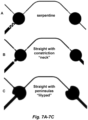
- a serpentine or S-curve fluid flow barrier structure or configuration is illustrated in Figure 7A .
- the fluid flow barrier structure or configuration comprises a void (e.g ., a sealed cavity) located in-line with the channel.
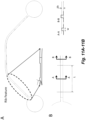
- a void fluid flow barrier structure or configuration introduces an abrupt and substantial change in geometry, including increases in height and width dimensions, as illustrated in Figures 9A-9B .
- one or more or a plurality of the cavities are not cylindrical and comprise a concave curvature at the junction of the cavity with one or more channels, such that the cavity forms peninsulas that extend from the cavity towards one or more channels (e.g ., the cavity is in the shape of a lilypad). See, e.g., Figure 7C .
- a sealed cavity or void is incorporated into a channel, e.g., as depicted in Figures 9A-9B .
- a region of reduced height e.g ., a rib feature
- a channel can have multiple fluid flow barrier structures or configurations, e . g , 2, 3, 4 or more fluid flow barriers.
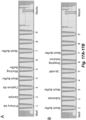
- one or more or a plurality of the cavities include a straight and perpendicular entrance of one or more channels into the cavity, such that there is a sharp change in geometry (e.g., 90°) where the channel enters the cavity, e.g ., as depicted in Figures 14A-14B .
- Perpendicular includes the intersection of a straight channel region with a small segment of a curved surface, as shown in Figures 14A-14B .
- the nodes are configured such that entrance (input, transfer) channel and exit (output, assay) channel junctions are located in different vertical planes, e.g ., as depicted in Figures 15A-15B .
- the input (transfer) channels can enter at one or more entrance points of the space above the node and the output (assay) channels can exit at one or more exit points at the bottom of the node.
- the input channels are located at or near the outer diameter of the cavity (e.g ., within about 1 mm of the outer edge of a 3 mm diameter cavity, e.g ., within the outer 1/3 of the diameter of the cavity) while the output channel is located at or near the center of the cavity (e.g., within about 1 mm of the center, e.g ., within the inner 1/3 of the diameter of the cavity).
- a defined amount of fluid remains in the source cavity in a region between the entrance and exit channels.
- valveless microfluidic flowchips described herein are based on networks of microfluidic cavities connected by microfluidic channels, which can be hydrophobic. Each cavity can be classified as either a reservoir or a node, and includes a pressure port via which gas pressure may be applied. Sequences of gas pressures, applied to reservoirs and nodes according to fluid transfer rules, enable fluid to be moved from any reservoir to any other reservoir in a system.
- valveless microfluidic flowchips can be designed from the basic components of reservoirs, nodes and channels to perform many different microfluidic tasks including, e.g ., homogenous and inhomogeneous assays and microwell plate interfacing.
- the systems are scalable to any number of fluid inputs and outputs, and they can be used to manipulate very small fluid volumes necessary for multiplexing samples with analytes to perform multiple simultaneous assays.
- a microfluidic cavity is an internal volume for accumulating fluid in the microfluidic flowchips.
- a reservoir is a microfluidic cavity that is connected to only one microfluidic channel.
- a node is a microfluidic cavity that is connected to more than one microfluidic channel.
- a channel is a microfluidic passageway between nodes or reservoirs.
- Each channel in the present valveless microfluidic system connects at least two cavities. Contemplated are flowchip designs where there are channel intersections and fluid flow is controlled by differential resistance in different channels.
- Nodes are designed to present lower resistance to fluid flow than are channels.
- the fluid flow resistance of a cavity or channel is inversely proportional to the square of its cross sectional area. Therefore the difference in flow resistance between a channel and a reservoir, or between a channel and a node, may be engineered via different cross sectional areas.
- Reservoirs store fluids; e.g ., samples or reagents.
- Nodes can store a fluid initially and also can store other fluids during a sequence of fluid transfer steps. Provisions for automated loading fluid into, or unloading fluid from, a reservoir may be provided, with a small plastic tube extending from a reservoir to a glass bottle or with an automated pipette station being examples.
- valveless microfluidic flowchips can be implemented in a variety of ways as long as: reservoirs, nodes, channels and pressure ports are provided; and resistance to fluid flow is greater in the channels than in the nodes.
- the channels are hydrophobic, e.g ., to prevent fluid flow when pressures at the two ends of a channel are equal or nearly so.
- fluid flow through microfluidic channels is controlled by gas pressure differences applied to the cavities, e.g ., reservoirs and nodes. Fluid flow through a hydrophobic channel exhibits a pronounced threshold effect. At first, no fluid flows as the pressure difference from one end of the channel to the other is increased.
- hydrophobicity of channels sets the threshold pressure difference, and the difference between high and low pressures used in a system is designed to be greater than the hydrophobic threshold pressure.
- the pressure is high at the source cavity end of a channel and low at the destination cavity end, fluid flows in the channel from the source cavity to the destination cavity.
- Intermediate gas pressure is insufficient to overcome the hydrophobic threshold, but if fluid is already flowing ( e.g ., by subjecting the source cavity to high gas pressure), intermediate gas pressure is sufficient to continue allowing the fluid flow, albeit at a reduced rate. If fluid is already flowing and the pressure is reduced to intermediate gas pressure at the source cavity end of a channel and remains low at the destination end of the channel, fluid continues flowing in the channel from the source cavity to the destination cavity, but air is not introduced into the channel.
- hydrophobic threshold pressure of hydrophobic channels keeps fluid in nodes and reservoirs from leaking into the channels when no pressure differences are applied.
- the threshold pressure is designed to be great enough to prevent fluid flow that might be driven by the hydrodynamic pressure caused by the weight of fluid in a reservoir or node, or by residual pressure differences that might exist when applied pressures are switched between high and low.
- a "hydrophobic channel” is defined as one that exhibits a pressure threshold that prevents fluid from leaking into the channel when the pressure difference between the two ends of the channel is less than a designated or threshold pressure.
- channels were designed to have about 1 kPa hydrophobic threshold pressure.
- valveless microfluidic flowchip includes a substrate layer, a hydrophobic fluid layer, and a pneumatic layer.
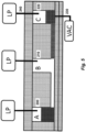
- Figure 2 illustrates a valveless microfluidic flowchip, seen in cross section.
- microfluidic flowchip 105 includes a substrate layer 110, a hydrophobic fluidic layer 115, and a pneumatic layer 120.
- Cavities in the hydrophobic fluidic layer are labeled A, B and C in Figure 2 and in Figures 3A-3F . Cavities A and B are connected by channel 125 while cavities B and C are connected by channel 130. Cavities A and C are classified as reservoirs because they are connected to only one channel each. Cavity B is classified as a node because it is connected to more than one channel: B is connected to both channel 125 and channel 130.
- Pressure sources 135, 140 and 145 are connected to reservoir A, node B and reservoir C, respectively, via gas tubes 150, 155 and 160, respectively.
- Each of the three pressure sources is capable of providing at least two different pressures: a high gas pressure and a low pressure.
- Labels HP, IP and LP in Figure 2 and in Figures 3A-3F refer to the capability of a pressure source to provide high, intermediate or low pressures, respectively.
- Pressure source 145 is also capable of providing a pressure that is less than atmospheric pressure; e.g ., a partial vacuum.
- substrate 110 may be made of glass, polydimethylsiloxane (PDMS), polyethylene terephthalate (PET), or plastic.
- Hydrophobic fluidic layer 115 may be made from PDMS.
- a mold for casting PDMS to define hydrophobic microfluidic channels may be produced with a programmable cutter for vinyl decals or defined photolithographically in an epoxy-based negative photoresist such as SU-8. After patterned PDMS is cured and removed from a mold, it may be bonded to a flat substrate.
- Pneumatic layer 120 may also be made from PDMS.
- Gas tubes may be made from polyetheretherketone (PEEK) tubing which forms convenient seals when inserted in appropriately sized holes in PDMS.
- Hydrophobic materials that are suitable alternatives to PDMS include polypropylene (PP), a cyclic olefin polymer (COP), a cyclic olefin copolymer (COC), fluorinated ethylene propylene (FEP) and polytetrafluoroethylene (PTFE). Published water contact angles for these materials are provided in Table 1.
- the polymers can be modified to increase their hydrophobicity through use of additives, surface coatings, or surface modifications.
- the cross-sectional dimensions of channels 125 and 130 can be in the range of about 25 ⁇ m to about 50 ⁇ m, 100 ⁇ m, 150 ⁇ m, or 200 ⁇ m (height) by about 25 ⁇ m to about 50 ⁇ m, 100 ⁇ m, 150 ⁇ m, 200 ⁇ m, 250 ⁇ m, 300 ⁇ m, 350 ⁇ m, 400 ⁇ m, 450 ⁇ m, or 500 ⁇ m (width).
- the sizes of reservoirs A and C, and of node B can be between about 1 mm to about 2 mm, 2.5 mm, 3 mm, 3.5 mm, 4 mm, 4.5 mm, 5 mm, 5.5 mm, or 6 mm in diameter.
- the distance between reservoir A and node B can be between about 5 mm to about 25 mm, 50 mm, 75 mm or 100 mm; the distance between node B and reservoir C can be within the same range.
- the cross-sectional areas of the cavities in typical flowchips are approximately 100 to 400 times greater than the cross-sectional areas of the channels. Therefore the flow resistance of the channels is about 10,000 to 160,000 times greater than the flow resistance of the cavities.
- Alternative designs for channels and cavities including fluid flow barrier structures or configurations lead to the flow resistance of such channels being about 20%, 50%, 100%, 200%, 500%, or 1000% greater than the flow resistance of non-altered channels.
- microfluidic flowchip 105 Another way to make a structure like microfluidic flowchip 105 involves hot embossing a hydrophobic thermoplastic polymer such as polypropylene (PP) or cyclic olefin polymer/copolymer (COP/COC) followed by solvent-assisted lamination to form enclosed, hydrophobic channels.
- PP polypropylene
- COP/COC cyclic olefin polymer/copolymer
- hydrophilic microfluidic channels formed in polycarbonate for example, may be made hydrophobic via chemical surface treatment.
- one or more or a plurality of the cavities can be connected with up to 4, 5, 6, 7, 8, 9, 10, 11, 12, 13, 14, 15 or 16 channels each.
- each network in the one or more networks comprises an input/output channel, the input/output channel having a greater resistance to fluid flow than that of the microfluidic channels.
- valveless microfluidic flowchips comprising those known in the art and the valveless microfluidic flowchips described above and herein.
- the systems comprise a pressure sequencer connected by pneumatic delivery channels to: (1) a high gas pressure gas source; (2) an intermediate gas pressure gas source; (3) a low pressure gas source; and optionally, (4) a partial vacuum pressure gas source; and to at least one cavity, e.g ., at least two cavities, in the flowchip.
- the pressure sequencer is configured to apply a high gas pressure, an intermediate gas pressure, a low gas pressure, and optionally, a partial vacuum pressure to at least one cavity according to pressure sequence data, where the high gas pressure is greater than the intermediate gas pressure, the intermediate gas pressure is greater than the low gas pressure, and the low gas pressure is greater than the partial vacuum gas pressure, and the partial vacuum pressure is less than atmospheric pressure.
- the flowchip can but need not additionally comprise microfluidic channels comprising a hydrostatic resistance barrier.
- the pressure sequencer is configured to concurrently apply a combination of gas pressure and partial vacuum to at least one cavity.
- Fluid transfer between cavities e.g ., between reservoirs and nodes is accomplished by switching pressures applied to each reservoir and node in a system according to a specific pattern.
- the origin or source cavity is a reservoir or node from which fluid is to be transferred.
- the destination cavity is the reservoir or node to which fluid is to be transferred.
- at least three gas pressures are used: high gas pressure, intermediate gas pressure and low gas pressure.
- at least four gas pressures are used: high gas pressure, intermediate gas pressure, low gas pressure and partial vacuum.
- a fluid transfer rule for the present valveless microfluidic systems may be summarized in the following steps:
- the fluid transfer rule may be executed by a pressure sequencer that is configured to execute the required sequence of pressures to accomplish any desired fluid transfer operation.
- the pressure sequencer receives pressure sequence data and/or instructions from, e.g., a controller. These data or instructions includes step by step instructions specifying what pressure is to be applied to each reservoir and node in device in order to carry out a specific fluid transfer operation. Fluid can be moved from any reservoir to any other reservoir in a reconfigurable microfluidic system by repeating the steps of the fluid transfer rule.
- a controller is part of a microfluidics system as described herein. Such system may be integrated with electronics or other processing logic for controlling their operation before, during, and after processing by a pressure sequencer.
- the processing logic may be referred to as the "controller,” which may control various components or subparts of the system or systems.
- the controller depending on the processing requirements and/or the type of system, may be programmed to control any of the processes disclosed herein, including the delivery of gases, pressure settings, vacuum settings, power settings, flow rate settings, fluid delivery settings, volume settings, positional and operation settings connected to or interfaced with a specific microfluidics system.
- the controller may be implemented in any of various integrated circuits, logic, memory, and/or software that receive instructions, issue instructions, control operation, enable endpoint measurements, and the like.
- the integrated circuits may include chips in the form of memory that store program instructions, digital signal processors (DSPs), chips defined as application specific integrated circuits (ASICs), and/or one or more microprocessors, or microcontrollers that execute program instructions (e.g ., software).
- Program instructions may be instructions communicated to the controller in the form of various individual settings (or program files), defining operational parameters for carrying out a particular process.
- the controller may have access to computer readable media such as storage media, computer storage media, or data storage devices (removable and non-removable) such as, for example, magnetic discs, optical disks, or tape.
- Computer storage media may include volatile and non-volatile, removable and non-removable media implemented in any method or technology for storage of information, such as computer readable instructions, data structures, program modules, or other data. Examples of computer storage media include RAM, ROM, EEPROM, flash memory or other memory technology, CD-ROM, digital versatile discs (DVD) or other optical storage, magnetic cassettes, magnetic tape, magnetic disk storage or other magnetic storage devices, or any other medium which can be used to store the information and which can be accessed by an application, module, or both.
- Any such computer storage media may be part of the device or accessible or connectable thereto.
- the computer storage media may be located remotely, e.g ., cloud storage, and accessed via a network or internet connection. Any method, application or module herein described may be implemented using computer readable/executable instructions that may be stored or otherwise held by such computer readable media and executed by the one or more processors.
- the controller may be a part of or coupled to a computer that is integrated with, coupled to the system, otherwise networked to the system, or a combination thereof.
- the controller may be in the "cloud" or all or a part of a host computer system, which can allow for remote access of the pressure sequencer.
- the host computer system and/or the controller can be connected to the internet ( e.g ., via a wired or wireless connection).
- the computer may enable remote access to the system to monitor current progress of fluidic operations, examine a history of past pressure sequencing operations, examine trends or performance metrics from a plurality of pressure sequencing operations, to change parameters of current processing, to set processing steps to follow a current processing, or to start a new process.
- a remote computer e.g . a server
- the remote computer may include a user interface that enables entry or programming of parameters and/or settings, which are then communicated to the system from the remote computer.
- the controller receives instructions in the form of data, which specify parameters for each of the processing steps to be performed during one or more operations. It should be understood that the parameters may be specific to the type of process to be performed and the type of tool that the controller is configured to interface with or control.
- the controller may be distributed, such as by comprising one or more discrete controllers that are networked together and working towards a common purpose, such as the processes and controls described herein.
- a distributed controller for such purposes would be one or more integrated circuits locally associated with one or more pressure sequencers in communication with one or more integrated circuits located remotely (such as part of a remote computer) that combine to control one or more pressure sequences.
- the controller might communicate with one or more of other pressure sequencers in fluid communication with one or more microfluidic chips, in sequence or in parallel, a main computer, or another controller.
- the controller may assist in detection of assay parameters (e.g ., reservoir pressures, reservoir volumes, fluid flow rate), and biomarker detection (e.g ., when performing an immunoassay).
- the controller may host a user-accessible platform for invoking services, such as reporting and analysis services, and for providing computational resources to effect machine learning techniques on the detection data.
- the pressure sequencer can be implemented as a set of electronically controlled pneumatic valves, e.g ., that are programmed using software (e.g ., Lab VIEW, National Instruments Corporation, MATLAB, Mathworks, Visual BASIC, C#, Python, or Java)), e.g ., running on a personal computer, a microcontroller or microprocessor.
- the pressure sequence data necessary to move fluid from one reservoir to another in a reconfigurable microfluidic device can be programmed or worked out manually.
- a graphical software program may be written that allows a user to select origin and destination reservoirs, with the program then generating appropriate pressure sequence data by repeated application of the fluid transfer rule. In this way an intuitive system may be created that permits users to perform arbitrary microfluidic experiments without needing to understand the fluid transfer rule or other system operation details.
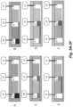
- Figures 3A-3F illustrate an implementation using the herein described systems and flowchips for transferring fluid from a source cavity (A) to a destination cavity (B) through a connecting channel.
- a high gas pressure (HP) is applied for a time t(1) to overcome the hydrostatic and hydrophobic barriers between the source cavity (A) and connected channel and start fluid flowing through the channel to the destination cavity (B) ( See, e.g., Figures 3A-3C ).
- the pressure on the source cavity (A) is then switched to an intermediate gas pressure (IP) for a time t(2) that will continue to move fluid through the channel and empty the source cavity (A) ( See, e.g., Figures 3D-3E ).
- IP intermediate gas pressure
- the force exerted by IP is less than the amount required to overcome the resistance or fluid flow barrier(s) at the channel/cavity interface when the source cavity (A) has emptied so fluid is not pushed down the channel.
- the destination cavity (B) is kept at low pressure (LP, atmospheric or ambient) during this transfer. At the end of this transfer event, the source cavity (A) is empty, the connecting channel is full, and the destination cavity (B) has been filled with fluid ( See, e.g., Figure 3F ).
- the total volume in the destination cavity (B) is the volume in the source cavity (A) minus the volume in the channel.
- the time t(1) is set so that at least about 10% up to about 70%, 75%, 80%, 85% or 90%, e.g ., between about 30% and about 70%, of the fluid in the source cavity (A) has been transferred.
- the time t(2) is set for a time period that is longer than the time required to transfer the remaining fluid in the source cavity (A).
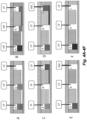
- Figures 4A-4F illustrate an implementation using the herein described systems and flowchips for transferring fluid from a source cavity (B) to a destination cavity (C) through a connecting channel and then evacuating or removing fluid from the destination cavity (C).
- a high pressure (HP) is applied for a time t(1) to cavities A and B to overcome the fluid flow barriers between the source cavity (B) and channel connected to cavity C and start fluid flowing through the channel to the destination cavity (C) ( See, e.g., Figures 4A-4B ). In this scenario fluid will remain in cavity A.
- the pressure on cavities A and B is then switched to an intermediate pressure (IP) for a time t(2) that will continue to move fluid through the B-C channel and empty the source cavity (B) ( See, e.g., Figure 4C ).
- IP intermediate pressure
- the force exerted by IP is less than the amount required to overcome the resistance or fluid flow barrier(s) at the channel/cavity interface when the source cavity (B) has emptied so fluid is not pushed down the channel.
- the destination cavity (C) is kept at low pressure (LP, atmospheric or ambient) during this transfer. At the end of this transfer event, cavity A remains full, the source cavity (B) is empty, the connecting channel is full, and the destination cavity (C) has been filled with fluid ( See, e.g., Figure 4C ).
- the total volume in the destination cavity (C) is the volume in the source cavity (B) minus the volume in the channel.
- the time t(1) is set so that at least about 10% up to about 70%, 75%, 80%, 85% or 90%, e.g ., between about 30% and about 70%, of the fluid in the source cavity (B) has been transferred.
- the time t(2) is set for a time period that is longer than the time required to transfer the remaining fluid in the source cavity (C).
- the pressure on the source cavity (C) is then switched to partial vacuum (VAC) for a time t(3) and fluid is removed from the source cavity (C) and channel B-C through the gas port ( See, e.g., Figures 4D-4E ). At the end of this event, cavity A remains full and the source cavity (B), channel B-C, and destination cavity (C) are empty ( See, e.g., Figure 4F ).
- a gas port is connected to this manifold at one or more cavities. Connection of the cavity to the manifold can be done through pre-formed holes in the bottom seal of the cavity or by penetration through the bottom seal of the flowchip when the flowchip is mounted on the bottom manifold ( e.g ., with a hollow needle).
- the bottom manifold can be connected to the same pressure and partial vacuum sources used for the top manifold or have separate pressure and partial vacuum sources.
- Figures 6A-6F illustrate an implementation using the herein described systems and flowchips for transferring fluid from a source cavity (B) to a destination cavity (C) through a connecting channel and then evacuating or removing fluid from the destination cavity (C) where destination cavity (C) has separate gas ports for applying pressure and evacuating fluid.
- a high pressure (HP) is applied for a time t(1) to cavities A and B to overcome the hydrostatic and hydrophobic barriers between the source cavity (B) and channel connected to cavity C and start fluid flowing through the channel to the destination cavity (C) ( See, e.g., Figures 6A-6B ). In this scenario fluid will remain in cavity A.
- the pressure on cavities A and B is then switched to an intermediate pressure (IP) for a time t(2) that will continue to move fluid through the B-C channel and empty the source cavity (B) (See, e.g., Figure 6C ).
- IP intermediate pressure
- the force exerted by IP is less than the amount required to overcome the resistance or fluid flow barrier(s) at the channel/cavity interface when the source cavity (B) has emptied so fluid is not pushed down the channel.
- the destination cavity (C) is kept at low pressure (LP, atmospheric or ambient) during this transfer. At the end of this transfer event, cavity A remains full, the source cavity (B) is empty, the connecting channel is full, and the destination cavity (C) has been filled with fluid (See, e.g., Figure 6C ).
- the pressure on the bottom gas port of source cavity (C) is then switched to partial vacuum (VAC) while the pressure on the top gas port is kept at low pressure for a time t(3) and fluid is removed from the source cavity (C) through the bottom gas port (See, e.g., Figures 6D-6E ).
- VAC partial vacuum
- the pressure on the top gas port is kept at low pressure for a time t(3) and fluid is removed from the source cavity (C) through the bottom gas port (See, e.g., Figures 6D-6E ).
- cavity A remains full
- the channel B-C remains full
- the source cavity (B) and destination cavity (C) are empty (See, e.g., Figure 6F ).
- a system for moving a quantity of liquid from a source cavity to a destination cavity and evacuation of fluid from the destination cavity in a network of microfluidic cavities, wherein the source cavity and the destination cavity are separated by a valveless microfluidic channel having a resistance to fluid flow greater than that of the source cavity comprising: (i) a receptacle for receiving and engaging with a flowchip comprising the network of microfluidic cavities; (ii) a pressure sequencer comprising a set of gas valves and configured to be connected to a first gas source for producing a high pressure in microfluidic cavities, a second gas source for producing a low pressure in microfluidic cavities, and a third gas source for producing an intermediate pressure in microfluidic cavities, and optionally a fourth source for producing a partial vacuum, wherein the high pressure is greater than the low pressure, the intermediate pressure is less than the high pressure but greater than the low pressure, and the intermediate pressure is insufficiently great to overcome resistance or barrier(s) to fluid flow
- an air-liquid interface at the entrance to the microfluidic channel provides an increased resistance or barrier(s) to fluid flow that prevents further fluid transfer when the source cavity is first emptied (or substantially emptied) of the liquid.
- the intermediate pressure is sufficient to push fluid out of the source cavity only so long as there is fluid in the cavity.
- the resistance to fluid transfer increases such the intermediate pressure is no longer sufficient to drive fluid through the channel.
- the pressure sequencer is configured to apply or follow a fluid transfer rule in which: (1) high gas pressure is applied to an origin or source cavity from which a fluid is transferred and low gas pressure is applied to a destination cavity to which the fluid is transferred, the high pressure being applied for a time t(1) sufficient to overcome hydrophobic and/or hydrostatic barriers and start fluid flowing from the origin or source cavity into a microfluidic channel connecting the origin or source cavity to the destination cavity; (2) intermediate pressure is applied to the origin or source cavity and low pressure is applied to the destination cavity such that fluid continues to move through the connecting channel, the intermediate pressure being applied for a time sufficient to empty the origin or source cavity of fluid but of a pressure insufficient to expel fluid out of the channel; whereby the origin or source cavity is emptied of fluid and the fluid is moved into the channel and destination cavity; and (3) optionally, partial vacuum is applied to the destination channel while low pressure is applied to the source cavity such that fluid is evacuated from the destination cavity through the gas port.
- partial vacuum is applied to the destination cavity through a separate port or channel located on the bottom surface of the destination cavity 220, or opposite side of the pressure ports, e.g ., so that less stress is applied to the manifold/flowchip interface, and fluid is evacuated from the bottom of the cavity.
- gas pressure is introduced into the destination cavity from the gas port above the top surface of the flowchip to facilitate removal of fluid from, and drying of the destination cavity by the partial vacuum port below the flowchip.
- the terms "above” and “below” are relative because the flowchip could be held in a vertical configuration. Gas pressure is applied above the meniscus of the fluid in the destination cavity and partial vacuum is concurrently applied below the fluid in the destination cavity, e.g ., on opposite sides of the fluid in the destination cavity, facilitating evacuation with continuous flow of fluid.
- an air-liquid interface at the entrance to the microfluidic channel provides an increased resistance or barrier(s) to fluid flow that prevents further fluid transfer when the source cavity is first emptied (or substantially emptied) of the liquid.
- the intermediate gas pressure is sufficient to push fluid out of the source cavity only so long as there is fluid in the cavity.
- the resistance to fluid transfer increases such the intermediate gas pressure is no longer sufficient to drive fluid through the channel.
- the pressure sequencer is configured to apply one or more pressure modes selected from the group consisting of constant pressure, pulsing pressures, increased ramping pressures and decreased ramping pressures.
- the pressure sequencer is configured to control applied pressure by applying pulsing pressures and using pulse width modulation (PWM), which may have a duty factor chosen to provide the desired pressure. For example, during operation, the duty factor may be adjusted to being in the range of about 1%, 5%, 10%, 20%, 30%, 40%, 50%, 60%, 70%, 80% or 90%.
- PWM pulse width modulation
- the pressure sequencer is configured to apply increased and/or decreased ramping pressures comprising rise and/or fall times in the range of about 10 msec to about 20 msec, 50 msec, 100 msec, 250 msec, 500 msec, 750 msec or 1 sec.
- high pressure can be in the range of about 5 kPa to about 100 kPa
- intermediate pressure can be in the range of about 1.0 kPa to about 10 kPa
- low pressure can be about 0 kPa or atmospheric or ambient pressure
- partial vacuum pressure can be less than atmospheric pressure, e.g ., about -6 kPa or lower, where all pressures are gauge pressures.
- the high pressure is in the range of about 5 kPa to about 60kPa, 70kPa, 80 kPa, 90kPa or 100 kPa, e.g., in the range of about 10 kPa to about 60 kPa.
- the intermediate pressure is in the range of about 1 kPa to about 5 kPa, 6kPa, 7kPa, 8 kPa, 9 kPa or 10 kPa.
- the partial vacuum pressure is in the range of about -5kPa to about -10kPa, -20kPa, -30kPa, -40kPa, -50kPa, -60kPa, -70kPa, -80kPa, -90kPa, or -100kPa.
- fluid flow rate under high gas pressure through the first plurality of microfluidic channels is from about 0.1 ⁇ L/second to about 0.2, 0.3, 0.4, 0.5, 0.6, 0.7, 0.8, 0.9, 1.0, 2.0, 3.0, 4.0, 5.0, 6.0, 7.0, 8.0, 9.0 or 10.0 ⁇ L/second.
- fluid flow rate under intermediate pressure through the first plurality of microfluidic channels is from about 0.01 ⁇ L/second to about 0.05, 0.1, 0.2, 0.3, 0.4, 0.5, 0.6, 0.7, 0.8, 0.9 or 1.0 ⁇ L/second.
- a plurality of the microfluidic channels present a hydrophobic pressure barrier to fluid flow that is less than the pressure difference between the high gas pressure and the low gas pressure.
- the pressure sequencer is configured to apply or follow a fluid transfer rule in which: (1) high gas pressure is applied to an origin or source cavity from which a fluid is transferred and low gas pressure is applied to a destination cavity to which the fluid is transferred, the high gas pressure being applied for a time t(1) sufficient to overcome hydrophobic and/or hydrostatic barriers and start fluid flowing from the origin or source cavity into a microfluidic channel connecting the origin or source cavity to the destination cavity; and (2) intermediate gas pressure is applied to the origin or source cavity and low pressure is applied to the destination cavity such that fluid continues to move through the connecting channel, the intermediate gas pressure being applied for a time t(2) sufficient to empty the origin or source cavity of fluid but of a pressure insufficient to expel fluid out of the channel; whereby the origin or source cavity is emptied of fluid and the fluid is moved into the channel and destination cavity.
- time t(1) is for a time period that is stopped or ended before the quantity of liquid is completely removed from the source cavity, e.g ., a time period sufficient to drain at least about 10% and up to about 90% of the fluid volume from the origin or source cavity.
- partial vacuum is applied to the destination cavity through a separate port or channel located on the bottom surface of the destination cavity 220, or opposite side of the pressure ports, e.g., so that less stress is applied to the manifold/flowchip interface, and fluid is evacuated from the bottom of the cavity.
- gas pressure is introduced into the destination cavity from the gas port above the top surface of the flowchip to facilitate removal of fluid from, and drying of the destination cavity by the partial vacuum port below the flowchip.
- the pressure sequencer is further connected to a very high gas pressure source, and the pressure sequencer is configured to apply a very high gas pressure, wherein the very high gas pressure is greater than the high gas pressure.
- the very high gas pressure is at least about 100 kPa, e.g., at least about 125 kPa, 150 kPa, 175 kPa, 200 kPa, or higher.
- the pressure sequencer is configured to apply or follow a fluid transfer rule in which the partial vacuum gas pressure is applied to a destination cavity to which a fluid is drawn via its input/output channel and low gas pressure is applied to any other cavity connected to the destination cavity by a channel.
- one or more networks comprise j rows and k columns of cavities, j and k being positive integers, cavities in each row or column being connected in series.
- a microfluidic flowchip having a source cavity and a destination cavity separated by a valveless microfluidic channel having a resistance to fluid flow greater than that of the source cavity.
- the methods comprise: (a) applying a high gas pressure to the source cavity, and all other cavities connected to the source cavity excepting the destination cavity, while applying a low pressure to the destination cavity to move a portion of the quantity of liquid from the source cavity, through the microfluidic channel, and to the destination cavity, wherein the high gas pressure is greater than the low pressure; and (b) applying an intermediate gas pressure to the source cavity before the quantity of liquid is completely removed from the source cavity, wherein the intermediate gas pressure is lower than the high gas pressure but higher than low pressure, and wherein the intermediate gas pressure is sufficiently great to push at least some of the quantity of liquid remaining after (a) to the destination cavity, but insufficiently great overcome resistance to fluid flow in the microfluidic channel, and thereby avoid introducing gas into the microfluidic channel.
- the one or more of the microfluidic channels are hydrophobic or comprise a hydrophobic coating.
- the intermediate gas pressure is insufficiently great to introduce gas into the microfluidic channel even when all of the quantity of liquid has been removed from the source cavity. In some embodiments, less than about 90% of the liquid is removed from the source cavity before applying the intermediate gas pressure. In some embodiments, a defined amount of fluid remains in the source cavity in a region between the entrance and exit channels. In some embodiments, the method is performed using a system as described above and herein.
- the methods comprise operating the valveless microfluidic system as described above and herein according to a set of pressure sequence data that causes the fluid to be drawn into the system from an origin or source cavity of the microwell plate and expelled into a destination cavity of the microwell plate, wherein air is not introduced into a microfluidic channel downstream of an origin or source cavity.
- the methods comprise operating the valveless microfluidic system as described above and herein, with pressure sequence data that causes each of the j samples to be exposed to the k reagents thereby producing j output solutions, wherein air is not introduced into a microfluidic channel downstream of an origin or source cavity.
- the methods comprise operating the valveless microfluidic system as described above and herein, wherein the system comprises two or more networks, the system operated according to pressure sequence data such that the pressure sequencer directs fluid flows in the system that cause different kinds of sample-analyte-capture-analyte reactions to occur in different networks, but the same kind of detection reagent reaction to occur in a plurality of networks, wherein air is not introduced into a microfluidic channel downstream of an origin or source cavity.
- the immunoassay fluid comprises a buffer having a pH in the range of 6-11, e.g., pH in the range of 6-9, e.g., a pH in the range of about 7-9 or a pH in the range of 9-11, one or more blocking agents or protein solutions and one or more surfactants.
- the immunoassay fluid comprises phosphate buffered saline (PBS), tris-buffered saline (TBS) or a bicarbonate buffer, albumin (e.g ., bovine serum albumin (BSA)), Tween-20, Triton-X, or other surfactants and optionally glycerol.
- PBS phosphate buffered saline
- TBSA tris-buffered saline
- BSA bovine serum albumin
- the methods can be executed analogously to the methods described in U.S. Patent Publication Nos. US2017/0021351 , US2017/0021352 and US2017/0021353 , with the improvement that the pressure sequencer is configured to switch from high gas pressure mode to intermediate gas pressure mode before the quantity of liquid is completely removed from the source cavity, thereby avoiding introduction of air bubbles into the microfluidic channel that connects the origin cavity with the destination cavity.
- FIG. 3A-3F A schematic representation of this process is shown in Figures 3A-3F .
- a high gas pressure (HP) e.g., in the range of about 5 kPa or 10 kPa to about 60 kPa or 100 kPa, is applied for a time t(1) to overcome the hydrophobic and hydrostatic barriers between the source cavity and connected channel and start fluid flowing through the channel to the destination cavity ( Figures 3A-3C ).
- the pressure on the source cavity is then switched to a second, intermediate gas pressure (IP), e.g ., in the range of about 0.5 kPa or 1.0 kPa to about 5 kPa or 10kPa, for a time t(2) that will continue to move fluid through the channel and empty the source cavity ( Figures 3D-3E ).
- IP intermediate gas pressure
- the force exerted by an intermediate gas pressure (IP) is less than the amount required to overcome the resistance or fluid flow barrier(s) at the cavity/channel interface when the source cavity has emptied so fluid is not pushed down the channel.
- the destination cavity is kept at a low pressure (LP, e.g ., atmospheric) during this transfer.
- LP low pressure
- the source cavity is empty, the connecting channel is full, and the destination cavity has been filled with fluid ( Figure 3F ).
- the total volume in the destination cavity is the volume in the source cavity minus the volume in the channel.
- the time t(1) is set so that 10% to 90% of the fluid in the source cavity has been transferred.
- the time t(2) is set so that is much longer than the time required to transfer the remaining fluid in the source cavity.
- 14 ⁇ l of fluid is transferred by HP and 6 ⁇ l of fluid by IP.
- the fluid should be completely transferred during the IP step after about 60 sec.
- the excess IP time accommodates for variation in fluid transfer rates caused by channel dimensional variations, presence of artifacts or contamination in channels, presence of air bubbles in channels, or other effects.
- the times t(1) and t(2) are configured so that the source cavity will not empty during the HP step and the total transfer time is minimized.
- the measured flowrate variation over multiple channels and multiple flowchips is approximately 12%, which gives a "3-sigma" maximum HP flowrate of 2.72 ⁇ l/sec. Under the above conditions the maximum amount of fluid transferred during HP will be 19 ⁇ l so the source cavity will not be emptied.
- the "3-sigma" minimum HP flowrate is 1.28 ⁇ l/sec, making the expected minimum amount of fluid transferred to be 9 ⁇ l. This means 11 ⁇ l will be transferred at the IP rate which will take 110 sec which is less than t(2). This method assures that all of the fluid will be transferred out of the source cavity, but air will not be forced through the channel and into the destination cavity.
- the time t(2) can be increased if desired to accommodate variations in the IP flowrate.
- the resistance at the WCI is a function of the surface and fluid properties and the channel dimensions.
- ⁇ fluid viscosity
- L channel length
- ⁇ channel width
- H channel height
- the fluid viscosity can be optimized to increase this resistance and allow higher values of IP to be used in the process.
- Additives such as glycerol, and other higher viscosity fluids have been mixed into assay reagents in order to increase this resistance. These fluids will evacuate from channels at higher IP values.
- a useful "assay buffer” solution for flowchips made from polypropylene (PP) contains PBS + 0.1% BSA + 0.001% Tween 20.
- a useful "assay buffer” solution for flowchips made from cyclic olefin copolymer (COC) contains PBS + 0.1% BSA + 0.001% Tween 20 + 10% glycerol.
- the channel geometry can be modified to increase the hydrostatic barrier (HSB) for example by introducing a "neck” or a "serpentine” structure at or near the WCI. Examples of these are shown in Figures 7A-7C .
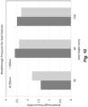
- the HSB pressures were measured for polydimethylsiloxane (PDMS) devices with these geometries and the results are given in Table 2, below, and which is also depicted in Figure 8 .
- PDMS polydimethylsiloxane
- the hydrostatic resistance or fluid flow barrier structures are designed so that there is an increase in both the hydrophobic barrier (HPB), which relates to the resistance of liquid moving from a cavity into a channel, and the hydrostatic barrier (HSB), which relates to the resistance of moving liquid from a channel. It is also critical to maintain adequate flowrates so that the fluid transfers can be performed in a reasonable amount of time, however. This is especially important for time-sensitive steps in an immunoassay like the substrate incubation time.
- the flowrates for an assay buffer were measured for the three structures at different applied pressures and the results are shown in Figure 8 . Some reduction in flowrates were observed, but were within an acceptable range.
- the channel geometry can be modified to include a sealed cavity, or void, along the length of the channel between two regular cavities.
- a void is characterized by its diameter and height and the presence of a void in a channel leads to an increase in the breakthrough pressure (BP) of the channel.
- the BP is defined as the pressure required to move fluid from a source cavity to a destination cavity.
- the BPs were measured for polydimethylsiloxane (PDMS) devices with void diameters of 250 ⁇ m and 500 ⁇ m, and void heights of 90 ⁇ m and 250 ⁇ m and the results are given in Figure 10 . In these cases the channel width and height were 50 ⁇ m.
- the channel geometry can be modified to include a region of reduced height (referred to herein as a rib or a rib feature), along the length of the channel between two cavities.
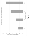
- a rib is characterized by its length, width, and height and the presence of a rib in a channel leads to an increase in the breakthrough pressure (BP) and capillary pressure of the channel.
- the BPs were measured for polydimethylsiloxane (PDMS) devices with channel widths of 50 ⁇ m and channel heights from 22 ⁇ m to 50 ⁇ m and the results are given in Figure 12 .
- the BPs were also compared to calculated capillary pressures for various rib geometries and those results are given in Figure 13 .
- a good correlation (R2 0.927) was observed between the BP and capillary pressure.
- the mold for injection molded microfluidic devices is typically formed by sandwiching two sides together: an A-side and a B-side.
- a standard method is to have the A-side contain fluidic channel features and the B-side contain cavity and support features. Cavities are commonly formed by cylindrical pins and junctions between cavities and channels are made where the end of these pins press against raised features, or landing pads, on the A-side that define the bottom of the cavities and channel connections. Limitations of alignment of the A-side and B-side requires that the landing pads be larger than the ends of the pins so that there is always a complete connection (i.e., full contact between surfaces) between those items. An example of this is shown in Figure 14A .
- Fig 14A shows a bottom view of the junction between a pin and a landing pad that has a single channel connection; the Middle image shows a cross sectional view of that region; the Right image shows a 3-dimensional top view of that region.
- a consequence of this assembly method is the formation of a lip which creates a microfluidic "ring" at the base of a cavity that is nominally the same height as the connecting channel (e.g., 50 ⁇ m). Fluid can be drawn through this ring by microcapillary forces and if two or more channels are connected to the same cavity (e.g., a node) the ring can form a microfluidic connection between those channels that can circumvent the hydrophobic barrier established between the cavity and channel.
- the connection geometry is flared with a radius of curvature defined by the machine tooling used to create the mold (see Fig 14A - Right). This smoothing of the channel junction can reduce the fluid flow barrier at the WCI.
- FIG 14B An improved device is shown in Figure 14B .
- the B-side pin is larger than the A-side landing pad. This provides the necessary tolerance for alignment of the two mold sides while eliminating the lip at the base of the cavity formed by those items. This removes microfluidic connections between two or more channels that have junctions with the same cavity.
- An additional improvement is that channels now go straight into the cavities making a sharp change in geometry between the channel and cavity, because the junction of the channel with the cavity is perpendicular. This increases fluid flow barriers into and out of a cavity and improves the ability to control fluid transfers.
- Fig 14B has all the WCIs in one plane at the bottom of a cavity.
- the lack of a microfluidic landing pad gap connection between channels reduces potential wicking, but fluidic connections can still be formed between two or more channels that lead to adverse effects on assay performance (e.g., cross-contamination).
- Figures 15A-15B A further improvement of such junctions is shown in Figures 15A-15B.
- Fig 15A shows a top 3-dimensional view of a cavity with entrance ports close to the bottom of the cavity.
- Fig 15B shows a bottom 3-dimensional view of channels and their junctions with a cavity.
- Fig 15C shows a cross sectional view of a Transfer Channel entrance port and an exit junction to an Assay Channel.
- a feature of this device is the Transfer channels enter the cavity in a plane that is above the bottom of the cavity. Fluid then exits the cavity into the Assay Channel at the bottom of the cavity. This provides a vertical separation between the junctions and further reduces the likelihood of fluidic connection between Transfer Channels and the Assay Channel.
- the geometry of the Entrance Port is also such that more sharp edges are formed then in the case of the device in Fig 14B . This will further increase fluid flow barriers into and out of these channels and improve ability of the device to control fluid transfers.
- Fig. 15 Improvement in fluid control provided by the cavity features shown in Fig. 15 was measured by observing passive leakage of a high surfactant fluid from a cavity into connecting channels. Images from this study are shown in Fig 16A and B .
- An aqueous solution with 0.1% Tween 20 and fluorescein dye (for visualization) was loaded into various cavities of flowchips and let to stand for 60 minutes. The bottoms of the cavities were imaged using a fluorescence microscope (Lumascope with 4x objective, 490 excitation, 530 nm emission from Etaluma, Carlsbad CA).
- a positive result for passive leakage was determined if fluid was observed to travel more than 1 mm into the channel.
- the percentage of channels exhibiting passive leakage was used to gauge the flowchip performance.
- For the device shown in Fig 14B with native COC surfaces approximately 50% of channels were observed to have passive leakage. The addition of hydrophobic surface coatings reduced this to less than 17%.
- the device shown in Fig 15 with native COC surfaces
- the method described in this example can be extended to use of n different HP settings where n>2. This can allow for more elegant control of fluid movements for running assays in flowchips with a wide variety of cavity and channel dimensions and multiple fluid types.
- multiple lower HP values can be used if both low and high surface tension fluids are required to perform an assay.
- multiple higher HP values can be used if there are different hydrophobic barriers present in a flowchip.
- a very high hydrophobic and/or hydrostatic barrier (or other barrier) can be used to keep fluids in a cavity for long term storage and/or transport.
- a much higher HP e.g ., > 100 kPa) can be used to break this barrier.
- Vacuum can also be used in the process to evacuate fluid from cavities and channels in order to restore hydrophobic and/or hydrostatic barriers and reduce potential mixing of residual fluids in channels.
- Inflammation is a complex event in which cells respond to various endogenous and exogenous stimuli.
- Factors such as tumor necrosis factor alpha (TNF- ⁇ ), interleukin-1 beta (IL-1 ⁇ ), and interferon gamma (IFN- ⁇ ) activate signaling pathways leading to the expression of cell-surface antigens that facilitate binding of immune cells to blood vessels.
- TNF- ⁇ tumor necrosis factor alpha
- IL-1 ⁇ interleukin-1 beta
- IFN- ⁇ interferon gamma
- a microfluidic flowchip was designed containing multiple reservoirs and nodes that accommodate the reagents required to perform an ELISA assay.
- the channel layout is shown in Figure 1A .
- the assay channel (from Well 3 to Well 8) has a cross-section of 50 ⁇ m by 200 ⁇ m while the other transfer channels have cross-sections of 50 ⁇ m by 50 ⁇ m.
- the flowchip was made out of COC using injection molding and the bottom surface was sealed with a COC film. Each reservoir has a capacity of ⁇ 30 ⁇ l and was filled with 20 ⁇ l of the appropriate assay reagent. Assays were performed using two separate protocols designated 1 st Half and 2 nd Half.
- the Capture and Primary antibodies are specific to each immunoassay and matched antibody pairs for the MCP-1, IL-8, and IL-6 assays were obtained from a commercial source (Biolegend, San Diego, CA).
- the buffers and Stop Solution are common to all three assays and were made using materials obtained from Sigma-Aldrich.
- the SA-HRP Becton Dickenson, San Diego, CA
- Substrate Abcam, Cambridge, MA
- the Primary Ab's were used at a concentration of 1 ⁇ g/ml and made by diluting stock Ab in an Assay Buffer solution containing PBS, bovine serum albumin (BSA), and Tween20.
- the Blocking Buffer consisted of BSA diluted in PBS.
- the SA-HRP was also diluted in Assay Buffer and used at a concentration of 200ng/ml.
- the Substrate solution was used as provided.
- two transfers occur as indicated by two sets of numbers in the parentheses.
- Each fluid transfer step from a source well to a destination well, followed a fluid transfer rule that included a HP portion to move the majority of fluid through a given channel followed by a longer LP portion to empty the source well without emptying the channel as described previously.
- the HP portion typically was between 5 and 20 sec while the LP portion typically was between 30 and 300 sec.
- Incubation in the assay channel was done using a different fluid transfer rule that included successive short HP transfers followed by a delay between transfers to allow interaction of the reagents with the assay channel walls. Delay times were typically between 5 and 60 sec with a total of 15 to 30 cycles used during an Incubation step.
- the total incubation time (number of cycles x delay time) is dependent on the assay and sensitivity required: longer incubation times in general provide higher sensitivity.
- a LP portion was used after the HP cycles of an Incubation step in order to empty the source well.
- the Removal steps were accomplished by applying a vacuum to the Waste reservoir and sealing off Well 9.
- the time to remove 20 ⁇ l from Well 8 was typically between 15 and 30 sec.
- the total time for the 1 st Half protocol was approximately 90 min and the total time for the 2 nd Half protocol approximately 45 min.
- the flowchips were removed from the system, placed in a plate reader (Tecan, Switzerland) and the absorbance at 450nm was read through Well 6 using a pre-defined protocol.
- Multiparametric inflammation response of primary human vascular endothelial cells was characterized after 20 hours of stimulation with known inflammatory cytokines.
- HUVEC cells were cultured for 48 hours in 96-well multiwell plates (MWP) and then were incubated with a cocktail of TNF- ⁇ , IL-1 ⁇ , and IFN- ⁇ at maximum concentrations of 5 ng/well, 1ng/well, and 100 ng/well respectively.
- MCP-1 96-well multiwell plates
- the cell supernatants were removed and the amount of IL-6, Il-8, and MCP-1 was measured in the supernatants using the microfluidic ELISA system.
- Supernatants were diluted by 4x in Assay Buffer and the amount of cytokine was quantified using a standard curve.
- IL-8 was not affected within the concentration range studied by MG-132 which is a proteasome inhibitor that has been reported to stimulate IL-8.
- This novel microfluidic ELISA system provides an efficient multiparametric assay method that can be used to test the efficacy of anti-inflammatory compounds and also provide significant insight into the mechanism of action by selective inhibition of markers triggered by different signaling pathways.
- Macrophages originate from blood monocytes that leave the circulation to differentiate into various tissues. Macrophages are involved in the detection and phagocytosis of bacteria and damaged cells. In addition, macrophages initiate inflammation by releasing cytokines that activate vascular cells and facilitate adhesion of cytokines to blood vessels and migration into the tissues. Differentiated THP-1 cells have been widely used as an in vitro model of macrophages in studies of macrophage involvement in inflammatory responses.
- the human monocytic cell line THP-1 can be differentiated to macrophages by phorbol 12-myristate 13-acetate (PMA) and activated by LPS. Activated THP-1 cells change morphology and secrete inflammatory cytokines.
- PMA phorbol 12-myristate 13-acetate
- THP-1 cells were stimulated with PMA and LPS for 48 hours. An increase of IL-8, IL-1b and TNF-a was observed upon PMA and LPS activation of THP-1 cells.
- kinase inhibitors SB202190 and PDTC were treated with the kinase inhibitors SB202190 and PDTC, and the antibiotic moxifloxacin prior to activation.
- a microfluidic flowchip was designed containing multiple reservoirs and nodes that accommodate the reagents required to perform an ELISA assay.
- the channel layout is shown in Figure 21A .
- the assay channel (from Well 3 to Well 9) has a cross-section of 50 ⁇ m by 300 ⁇ m and length of 25 mm while the other transfer channels have cross-sections of 50 ⁇ m by 50 ⁇ m.
- Figure 21B shows a zoomed region of one microfluidic network including void and rib features in transfer channels.
- the flowchip was made out of COC using injection molding and the bottom surface was sealed with a COC film. Each reservoir has a capacity of ⁇ 30 ⁇ l and was filled with 20 ⁇ l of the appropriate assay reagent.
- the Capture and Primary antibodies are specific to each immunoassay and matched antibody pairs for the IL-8, IL-1 ⁇ , and TNF ⁇ assays were obtained from a commercial source (Biolegend, San Diego, CA).
- the buffers and Stop Solution are common to all three assays and were made using materials obtained from Sigma-Aldrich.
- the Avidin-HRP (Biolegend, San Diego, CA) and Substrate (Abcam, Cambridge, MA) were also common to each assay.
- the Capture Ab's were used at a concentration of 10 ⁇ g/ml and made by diluting stock Ab in a Coating Buffer solution containing phosphate buffered saline (PBS).
- PBS phosphate buffered saline
- the Primary Ab's were used at a concentration of 1 ⁇ g/ml and made by diluting stock Ab in an Assay Buffer solution containing PBS, bovine serum albumin (BSA), and Tween20.
- the Blocking Buffer consisted of BSA diluted in PBS.
- the Avidin-HRP was also diluted in Assay Buffer and used at a concentration of 200ng/ml.
- the Substrate solution was used as provided.
- two transfers occur as indicated by two sets of numbers in the parentheses.
- Each fluid transfer step from a source well to a destination well, followed a fluid transfer rule that included a HP portion to move the majority of fluid through a given channel followed by a longer LP portion to empty the source well without emptying the channel as described previously.
- the HP portion typically was between 5 and 20 sec while the LP portion typically was between 30 and 300 sec.
- Incubation in the assay channel was done using a different fluid transfer rule that included successive short HP transfers followed by a delay between transfers to allow interaction of the reagents with the assay channel walls. Delay times were typically between 5 and 60 sec with a total of 15 to 30 cycles used during an Incubation step.
- the total incubation time (number of cycles x delay time) is dependent on the assay and sensitivity required: longer incubation times in general provide higher sensitivity.
- a LP portion was used after the HP cycles of an Incubation step in order to empty the source well. The Removal steps were accomplished by applying a vacuum to the Waste port. The time to remove 20 ⁇ l from Well 9 was typically between 15 and 30 sec. The total time for the complete assay protocol was approximately 150 min. At the end of the protocol the flowchips were removed from the system, placed in a plate reader (Tecan, Switzerland) and the absorbance at 450nm was read through Well 6 using a pre-defined protocol.
- FIG. 23A shows standard curves for an IL-6 assay run using the flowchip device shown in Figure 1 and using the protocol in Table 3 (FC-1) compared to that from a flowchip device in Figure 21 using the protocol in Table 4 (FC-2).
- FC-1 protocol in Table 3
- FC-2 protocol in Table 4
- the improvement in assay performance as gauged by assay window (High Conc SignalBlank Signal), signal standard deviation, and Limit of Detection (LOD) is given in Figure 23B .
- THP-1 cells Inflammation response of THP-1 cells was characterized after differentiation with PMA and stimulation with LPS. Upon stimulation, differentiated THP-1 cells will adhere to the plate and secrete upregulate cytokines. THP-1 cells were plated 20,000 cells per well in a 96-well plate and incubated for 48 hr. Next, they were stimulated with a mix of PMA & LPS for 24 hr (0-5 pg/mL of PMA, and 0-100 pg/mL LPS). Anti-inflammatory compounds were added 2 hr prior to cytokine stimulation. After incubation, 60 ⁇ l of supernatant was taken for ELISA analysis from each well. The samples were analyzed fresh or stored at -70C for subsequent analysis.
- Inflammation is triggered by activation of receptors with cytokines leading to a cascade of signaling events.
- Kinases activate transcription factors that up-regulate adhesion molecules and cytokines (markers). Different markers are under control of different pathways and transcription factors.
- 3 - Moxifloxacin inhibits the enzyme bacterial DNA gyrase and prevents replication of bacterial DNA during bacterial growth and reproduction.
- the response of IL-8, TNF ⁇ , and IL-1 ⁇ were measured as a function of concentration of those compounds.
- the response curves for IL-8 are shown in Figure 25A .
- Each response curve was fit with a 4-parameter function and EC 50 values were measured.
- the results for all three cytokines is given in Figure 25B .
Landscapes
- Chemical & Material Sciences (AREA)
- Health & Medical Sciences (AREA)
- Hematology (AREA)
- Chemical Kinetics & Catalysis (AREA)
- Clinical Laboratory Science (AREA)
- General Health & Medical Sciences (AREA)
- Analytical Chemistry (AREA)
- Dispersion Chemistry (AREA)
- Life Sciences & Earth Sciences (AREA)
- Immunology (AREA)
- Molecular Biology (AREA)
- Engineering & Computer Science (AREA)
- Physics & Mathematics (AREA)
- Biomedical Technology (AREA)
- Urology & Nephrology (AREA)
- Fluid Mechanics (AREA)
- Cell Biology (AREA)
- Microbiology (AREA)
- Food Science & Technology (AREA)
- Medicinal Chemistry (AREA)
- Biotechnology (AREA)
- Biochemistry (AREA)
- General Physics & Mathematics (AREA)
- Pathology (AREA)
- Automatic Analysis And Handling Materials Therefor (AREA)
- Physical Or Chemical Processes And Apparatus (AREA)
Claims (12)
- System zum Bewegen einer Flüssigkeitsmenge von einem Ursprungs- oder Quellhohlraum zu einem Zielhohlraum in einem Netzwerk von Mikrofluidhohlräumen, wobei der Ursprungs- oder Quellhohlraum und der Zielhohlraum durch einen ventillosen Mikrofluidkanal getrennt sind, der einen Strömungswiderstand hat, der größer als der des Quellhohlraums ist, wobei das System enthält:eine Buchse zum Aufnehmen eines Flowchips, der das Netzwerk von Mikrofluidhohlräumen enthält, undzum in Eingriff Gelangen damit; undeinen Drucksequenzer, der einen Satz von Gasventilen enthält und konfiguriert ist, mit einer ersten Gasquelle zum Erzeugen eines hohen Gasdrucks in Mikrofluidhohlräumen, einer zweiten Gasquelle zum Erzeugen eines niedrigen Drucks in Mikrofluidhohlräumen, und einer dritten Gasquelle zum Erzeugen eines dazwischenliegenden Gasdrucks in Mikrofluidhohlräumen verbunden zu werden, wobei der hohe Gasdruck höher als der niedrige Druck ist, der dazwischenliegende Gasdruck niedriger als der hohe Gasdruck, aber höher als der niedrige Druck ist, und der dazwischenliegende Gasdruck nicht ausreichend groß ist, um den Strömungswiderstand in dem Mikrofluidkanal zu überwinden, wenn der Quellhohlraum im Wesentlichen leer von der Flüssigkeit ist, wobei der Drucksequenzer jeden Druckzustand auf jeden Hohlraum aufbringen kann; dadurch gekennzeichnet, dass das System weiter enthält einen Regler, der konfiguriert ist, den Drucksequenzer zu steuern:(a) den hohen Gasdruck auf einen beliebigen Hohlraum (außer dem Zielhohlraum) anzuwenden, der mit dem Ursprungs- oder Quellhohlraum über einen ersten Kanal verbunden ist, und während dessen den niedrigen Gasdruck auf einen beliebigen Hohlraum (außer dem Zielhohlraum) anzuwenden, der mit dem Zielhohlraum über einen zweiten Kanal verbunden ist, zum Bewegen eines Teils der Flüssigkeitsmenge von dem Ursprungs- oder Quellhohlraum, durch den Mikrofluidkanal und zu dem Zielhohlraum, und(b) einen dazwischenliegenden Gasdruck auf den Ursprungs- oder Quellhohlraum durch den ersten Kanal aufzubringen, bevor die Flüssigkeitsmenge vollständig aus dem Quellhohlraum entfernt ist, wobei der dazwischenliegende Gasdruck ausreichend hoch ist, zumindest einen Teil der Flüssigkeitsmenge, die nach (a) verbleibt, zu dem Zielhohlraum zu drücken, aber das Eindringen von Gas in den Mikrofluidkanal verhindert.
- System nach Anspruch 1, wobei der Drucksequenzer konfiguriert ist, einen Druckmodus oder mehrere Druckmodi aufzubringen, der/die ausgewählt ist/sind aus der Gruppe bestehend aus konstantem Druck, pulsierendem Druck, ansteigenden Rampendrücken und abfallenden Rampendrücken, und
wobei optional der Drucksequenzer konfiguriert ist, pulsierende Drücke und eine Pulsweitenmodulation (PWM) mit einem Tastverhältnis im Bereich von 1% bis 90% aufzubringen. - System nach Anspruch 2, wobei der Drucksequenzer konfiguriert ist, ansteigende und/oder abfallende Rampendrücke aufzubringen mit Anstiegs- und/oder Abfallzeiten im Bereich von 10 msec bis 1 sec.
- System nach einem der vorhergehenden Ansprüche, wobei ein oder mehrere Mikrofluidkanäle hydrophob sind oder eine hydrophobe Beschichtung aufweisen.
- System nach einem der vorhergehenden Ansprüche, wobei eine Mehrzahl der Hohlräume einen geraden und senkrechten Eingang von einem Kanal oder mehreren Kanälen in den Hohlraum aufweist, so dass es eine starke Veränderung der Geometrie gibt, wo der Kanal in den Hohlraum eintritt.
- System nach einem der vorhergehenden Ansprüche, wobei:i) der hohe Gasdruck im Bereich von 5 kPa bis 100 kPa ist; und/oderii) der dazwischenliegende Gasdruck im Bereich von 0,5 kPa bis 10 kPa ist.
- System nach einem der vorhergehenden Ansprüche, wobei eine Mehrzahl der Mikrofluidkanäle eine hydrophobe Druckbarriere gegenüber Fluidströmung bildet, die geringer als die Druckdifferenz zwischen dem hohen Gasdruck und dem niedrigen Gasdruck ist.
- System nach einem der vorhergehenden Ansprüche, wobei der Drucksequenzer konfiguriert ist, einer Fluidtransferregel zu folgen, bei der:(1) hoher Gasdruck auf einen Ursprungs- oder Quellhohlraum, aus dem ein Fluid transferiert wird, aufgebracht wird, und niedriger Gasdruck auf einen Zielhohlraum, zu dem das Fluid transferiert wird, aufgebracht wird, wobei der hohe Gasdruck für eine Zeit t(1) aufgebracht wird, die ausreichend ist, hydrophobe und/oder hydrostatische Barrieren zu überwinden und dass Fluid beginnt, aus dem Ursprungs- oder Quellhohlraum in einen Mikrofluidkanal zu fließen, der den Ursprungs- oder Quellhohlraum mit dem Zielhohlraum verbindet; und(2) dazwischenliegender Gasdruck auf den Ursprungs- oder Quellhohlraum aufgebracht wird und niedriger Gasdruck auf den Zielhohlraum aufgebraucht wird, so dass sich das Fluid weiter durch den Verbindungskanal bewegt, wobei der dazwischenliegende Gasdruck für eine Zeit t(2) aufgebracht wird, die ausreichend ist, den Ursprungs- oder Quellhohlraum von Fluid zu leeren, aber einen Druck hat, der nicht ausreichend ist, Fluid aus dem Kanal auszustoßen; wodurch der Ursprungs- oder Quellhohlraum von Fluid geleert wird und das Fluid in den Kanal und den Zielhohlraum bewegt wird.
- System nach einem der vorhergehenden Ansprüche, wobei der Drucksequenzer konfiguriert ist, einer Fluidtransferregel zu folgen, bei der weiter:
(3) Teilvakuum auf den Zielkanal über einen vierten Kanal aufgebracht wird, während niedriger Druck auf den Quellhohlraum durch den zweiten Kanal aufgebracht wird, so dass Fluid aus dem Zielhohlraum durch den Gasport abtransportiert wird. - System nach Anspruch 9, wobei der Drucksequenzer konfiguriert ist, gleichzeitig eine Kombination aus Gasdruck und Teilvakuum auf zumindest einen Hohlraum aufzubringen.
- System nach einem der Ansprüche 8 oder 9, wobei das Teilvakuum auf den Zielhohlraum durch einen Port oder einen Kanal in Fluidverbindung mit der Bodenfläche des Zielhohlraums aufgebracht wird, und Fluid von der Bodenfläche des Zielhohlraums abtransportiert wird.
- Verfahren zum Bewegen einer Flüssigkeitsmenge von einem Quellhohlraum zu einem Zielhohlraum in einem Netzwerk von Mikrofluidhohlräumen, wobei der Quellhohlraum und der Zielhohlraum durch einen ventillosen Mikrofluidkanal getrennt sind, der einen Strömungswiderstand hat, der größer als der des Quellhohlraums ist, wobei das Verfahren gekennzeichnet ist, dadurch, dass es enthält:(a) Aufbringen eines hohen Gasdrucks auf einen beliebigen Hohlraum (außer dem Zielhohlraum), der mit dem Ursprungs- oder Quellhohlraum über einen ersten Kanal verbunden ist, und während dessen Aufbringen des niedrigen Gasdrucks auf einen beliebigen Hohlraum (außer dem Zielhohlraum, der mit dem Zielhohlraum über einen zweiten Kanal verbunden ist, zum Bewegen eines Teils der Flüssigkeitsmenge von dem Quellhohlraum, durch den Mikrofluidkanal und zu dem Zielhohlraum, wobei der hohe Gasdruck höher als der niedrige Druck ist; und(b) Aufbringen eines dazwischenliegenden Gasdrucks auf den Quellhohlraum durch den ersten Kanal, bevor die Flüssigkeitsmenge vollständig aus dem Quellhohlraum entfernt ist, wobei der dazwischenliegende Gasdruck niedriger als der hohe Gasdruck, aber höher als der niedrige Gasdruck ist, und wobei der dazwischenliegende Gasdruck ausreichend hoch ist, zumindest einen Teil der Flüssigkeitsmenge, die nach (a) verbleibt, zu dem Zielhohlraum zu drücken, aber nicht ausreichend hoch ist, den Strömungswiderstand in dem Mikrofluidkanal zu überwinden, und damit das Eindringen von Gas in den Mikrofluidkanal verhindert.
Applications Claiming Priority (2)
| Application Number | Priority Date | Filing Date | Title |
|---|---|---|---|
| US201862664700P | 2018-04-30 | 2018-04-30 | |
| PCT/US2019/029879 WO2019213060A1 (en) | 2018-04-30 | 2019-04-30 | Valveless fluidic switching flowchip and uses thereof |
Publications (3)
| Publication Number | Publication Date |
|---|---|
| EP3787795A1 EP3787795A1 (de) | 2021-03-10 |
| EP3787795A4 EP3787795A4 (de) | 2022-01-26 |
| EP3787795B1 true EP3787795B1 (de) | 2024-10-30 |
Family
ID=68292045
Family Applications (1)
| Application Number | Title | Priority Date | Filing Date |
|---|---|---|---|
| EP19796922.3A Active EP3787795B1 (de) | 2018-04-30 | 2019-04-30 | Ventilloser fluidischer schalt-flowchip und verwendungen davon |
Country Status (5)
| Country | Link |
|---|---|
| US (2) | US11376589B2 (de) |
| EP (1) | EP3787795B1 (de) |
| CN (1) | CN112512688A (de) |
| CA (1) | CA3098905A1 (de) |
| WO (1) | WO2019213060A1 (de) |
Families Citing this family (3)
| Publication number | Priority date | Publication date | Assignee | Title |
|---|---|---|---|---|
| EP3787795B1 (de) | 2018-04-30 | 2024-10-30 | Protein Fluidics, Inc. | Ventilloser fluidischer schalt-flowchip und verwendungen davon |
| CA3154534A1 (en) * | 2022-04-07 | 2023-10-07 | Wasim Kapadia | Microfluidic viscometer for measuring the viscosity of microliter-volume liquid samples |
| DE102022213554B4 (de) | 2022-12-13 | 2026-04-30 | Robert Bosch Gesellschaft mit beschränkter Haftung | Vorrichtung und Verfahren zum Splitten dreidimensionaler Agglomerate |
Family Cites Families (43)
| Publication number | Priority date | Publication date | Assignee | Title |
|---|---|---|---|---|
| US3993062A (en) | 1975-11-03 | 1976-11-23 | Baxter Laboratories, Inc. | Hydrophobic valve |
| US5726404A (en) | 1996-05-31 | 1998-03-10 | University Of Washington | Valveless liquid microswitch |
| US6143248A (en) | 1996-08-12 | 2000-11-07 | Gamera Bioscience Corp. | Capillary microvalve |
| US6090251A (en) | 1997-06-06 | 2000-07-18 | Caliper Technologies, Inc. | Microfabricated structures for facilitating fluid introduction into microfluidic devices |
| US6012902A (en) | 1997-09-25 | 2000-01-11 | Caliper Technologies Corp. | Micropump |
| US20040202579A1 (en) | 1998-05-08 | 2004-10-14 | Anders Larsson | Microfluidic device |
| AU5878900A (en) | 1999-06-19 | 2001-01-09 | Orchid Biosciences, Inc. | Microfluidic device interface |
| US6811668B1 (en) | 1999-06-22 | 2004-11-02 | Caliper Life Sciences, Inc. | Apparatus for the operation of a microfluidic device |
| US7601270B1 (en) | 1999-06-28 | 2009-10-13 | California Institute Of Technology | Microfabricated elastomeric valve and pump systems |
| CA2408574A1 (en) | 2000-05-24 | 2001-11-29 | Micronics, Inc. | Microfluidic concentration gradient loop |
| US6773566B2 (en) | 2000-08-31 | 2004-08-10 | Nanolytics, Inc. | Electrostatic actuators for microfluidics and methods for using same |
| US20020189947A1 (en) | 2001-06-13 | 2002-12-19 | Eksigent Technologies Llp | Electroosmotic flow controller |
| US20040109793A1 (en) | 2002-02-07 | 2004-06-10 | Mcneely Michael R | Three-dimensional microfluidics incorporating passive fluid control structures |
| ATE355128T1 (de) * | 2002-09-06 | 2006-03-15 | Epigem Ltd | Modulares mikrofluidsystem |
| US7094345B2 (en) | 2002-09-09 | 2006-08-22 | Cytonome, Inc. | Implementation of microfluidic components, including molecular fractionation devices, in a microfluidic system |
| US6911132B2 (en) | 2002-09-24 | 2005-06-28 | Duke University | Apparatus for manipulating droplets by electrowetting-based techniques |
| US7445926B2 (en) | 2002-12-30 | 2008-11-04 | The Regents Of The University Of California | Fluid control structures in microfluidic devices |
| KR100537504B1 (ko) | 2003-01-20 | 2005-12-19 | 삼성전자주식회사 | 생물학적 시료 내에서의 단백질 검출을 위한 자동화된 유동 시스템 |
| US7011793B2 (en) | 2003-05-15 | 2006-03-14 | Kionix, Inc. | Reconfigurable modular microfluidic system and method of fabrication |
| US7524464B2 (en) | 2003-09-26 | 2009-04-28 | Ahn Chong H | Smart disposable plastic lab-on-a-chip for point-of-care testing |
| US20050217742A1 (en) | 2004-03-31 | 2005-10-06 | Sebastian Bohm | Microfluidic circuit including an array of triggerable passive valves |
| EP1838431A4 (de) | 2004-12-03 | 2012-08-22 | California Inst Of Techn | Mikrofluidikvorrichtungen mit kreisläufen für chemische reaktionen |
| US20070113908A1 (en) | 2005-11-18 | 2007-05-24 | The Ohio State University And Bioloc, Inc. | Valve for microfluidic chips |
| US20090165876A1 (en) | 2005-11-22 | 2009-07-02 | Micah James Atkin | Microfluidic Structures |
| US7976795B2 (en) | 2006-01-19 | 2011-07-12 | Rheonix, Inc. | Microfluidic systems |
| FR2897282B1 (fr) * | 2006-02-16 | 2008-05-30 | Commissariat Energie Atomique | Procede de controle de l'avancee d'un liquide dans un compos ant microfluidique |
| ES2393758T3 (es) | 2006-03-15 | 2012-12-27 | Micronics, Inc. | Ensayos integrados de ácidos nucleicos |
| US8142738B2 (en) * | 2006-12-07 | 2012-03-27 | Brand Gmbh + Co Kg | Bottle top dispenser for handling liquids |
| WO2008103824A1 (en) | 2007-02-23 | 2008-08-28 | Chinese Academy Of Inspection And Quarantine (Caiq) | Sensitivity-enhanced dot-antibody linked immunogold assay for virus detection |
| US8075854B2 (en) | 2007-11-08 | 2011-12-13 | The Ohio State University Research Foundation Bioprocessing Innovative Company | Microfluidic chips for rapid multiplex ELISA |
| US8122901B2 (en) | 2008-06-30 | 2012-02-28 | Canon U.S. Life Sciences, Inc. | System and method for microfluidic flow control |
| US20110301535A1 (en) | 2008-10-10 | 2011-12-08 | The Regents Of The University Of Michigan | Microfluidic control systems |
| US8354080B2 (en) * | 2009-04-10 | 2013-01-15 | Canon U.S. Life Sciences, Inc. | Fluid interface cartridge for a microfluidic chip |
| EA024999B1 (ru) | 2009-11-24 | 2016-11-30 | Опкоу Дайагностикс, Ллк. | Смешивание и доставка текучих сред в микрофлюидных системах |
| CA2786569C (en) | 2010-01-29 | 2019-04-09 | Perkinelmer Health Sciences, Inc. | Sample-to-answer microfluidic cartridge |
| US20130287613A1 (en) * | 2010-10-07 | 2013-10-31 | Vanderbilt University | Peristaltic micropump and related systems and methods |
| US9829451B2 (en) | 2011-10-09 | 2017-11-28 | Simon Fraser University | Microfluidic reconfiguration device for multi-plexed sample analysis |
| SG11201405072XA (en) * | 2012-02-21 | 2014-09-26 | Fluidigm Corp | Method and systems for microfluidic logic devices |
| WO2013181656A1 (en) | 2012-06-01 | 2013-12-05 | President And Fellows Of Harvard College | Microfluidic devices formed from hydrophobic paper |
| US9956558B2 (en) | 2015-07-24 | 2018-05-01 | HJ Science & Technology, Inc. | Reconfigurable microfluidic systems: homogeneous assays |
| US9733239B2 (en) | 2015-07-24 | 2017-08-15 | HJ Science & Technology, Inc. | Reconfigurable microfluidic systems: scalable, multiplexed immunoassays |
| US9956557B2 (en) * | 2015-07-24 | 2018-05-01 | HJ Science & Technology, Inc. | Reconfigurable microfluidic systems: microwell plate interface |
| EP3787795B1 (de) | 2018-04-30 | 2024-10-30 | Protein Fluidics, Inc. | Ventilloser fluidischer schalt-flowchip und verwendungen davon |
-
2019
- 2019-04-30 EP EP19796922.3A patent/EP3787795B1/de active Active
- 2019-04-30 CN CN201980044332.0A patent/CN112512688A/zh active Pending
- 2019-04-30 US US16/398,859 patent/US11376589B2/en active Active
- 2019-04-30 WO PCT/US2019/029879 patent/WO2019213060A1/en not_active Ceased
- 2019-04-30 CA CA3098905A patent/CA3098905A1/en active Pending
-
2022
- 2022-05-23 US US17/664,594 patent/US11839873B2/en active Active
Also Published As
| Publication number | Publication date |
|---|---|
| EP3787795A1 (de) | 2021-03-10 |
| EP3787795A4 (de) | 2022-01-26 |
| US20190329247A1 (en) | 2019-10-31 |
| CN112512688A (zh) | 2021-03-16 |
| US11839873B2 (en) | 2023-12-12 |
| US20220362763A1 (en) | 2022-11-17 |
| CA3098905A1 (en) | 2019-11-07 |
| US11376589B2 (en) | 2022-07-05 |
| WO2019213060A1 (en) | 2019-11-07 |
Similar Documents
| Publication | Publication Date | Title |
|---|---|---|
| US11839873B2 (en) | Valveless fluidic switching flowchip and uses thereof | |
| US12337316B2 (en) | Plasma separating microfluidic device | |
| CN102740975B (zh) | 微流体系统中的流体混合和递送 | |
| Hemmig et al. | Transposing lateral flow immunoassays to capillary-driven microfluidics using self-coalescence modules and capillary-assembled receptor carriers | |
| CN105026932B (zh) | 微流控分配设备 | |
| CN105848783B (zh) | 微流体装置、使用和方法 | |
| US9534200B2 (en) | Microstructure for particle and cell SEparation, identification, sorting, and manipulation | |
| US7223371B2 (en) | Microfluidic channel network device | |
| Saias et al. | Design, modeling and characterization of microfluidic architectures for high flow rate, small footprint microfluidic systems | |
| JP2014525569A (ja) | 予めプログラムされた自己出力型マイクロ流体回路のための方法およびシステム | |
| JP2003527616A (ja) | さらなる周辺チャンネルを有する微小流動デバイスおよびシステム | |
| CN105555406B (zh) | 用于执行聚合酶链式反应的分析单元、用于运行以及用于制造这样的分析单元的方法 | |
| Tottori et al. | Degas-driven deterministic lateral displacement in poly (dimethylsiloxane) microfluidic devices | |
| Dharmaraja et al. | Programming paper networks for point of care diagnostics | |
| JP2004000163A (ja) | 細胞の処理に用いるセル | |
| US9733239B2 (en) | Reconfigurable microfluidic systems: scalable, multiplexed immunoassays | |
| JP2007121275A (ja) | マイクロチップ、このマイクロチップを用いた液体の混合方法及び血液検査方法 | |
| JP2007136379A (ja) | マイクロリアクタおよびその製造方法 | |
| CN210079551U (zh) | 微流控芯片及其胶塞防回流结构 | |
| CN108698003A (zh) | 微流体混合装置和方法 | |
| EP1261426B1 (de) | Testkarte und verfahren ihrer verwendung | |
| JP2006153609A (ja) | 流体搬送装置及び該装置を用いた流体搬送方法 | |
| CN113893892B (zh) | 一种基于微流控芯片的纳米孔及其制备方法 | |
| CN118218034A (zh) | 微流控芯片及微流控系统、其使用方法 | |
| CA2992434C (en) | Reconfigurable microfluidic systems: scalable, multiplexed immunoassays |
Legal Events
| Date | Code | Title | Description |
|---|---|---|---|
| STAA | Information on the status of an ep patent application or granted ep patent |
Free format text: STATUS: THE INTERNATIONAL PUBLICATION HAS BEEN MADE |
|
| PUAI | Public reference made under article 153(3) epc to a published international application that has entered the european phase |
Free format text: ORIGINAL CODE: 0009012 |
|
| STAA | Information on the status of an ep patent application or granted ep patent |
Free format text: STATUS: REQUEST FOR EXAMINATION WAS MADE |
|
| 17P | Request for examination filed |
Effective date: 20201026 |
|
| AK | Designated contracting states |
Kind code of ref document: A1 Designated state(s): AL AT BE BG CH CY CZ DE DK EE ES FI FR GB GR HR HU IE IS IT LI LT LU LV MC MK MT NL NO PL PT RO RS SE SI SK SM TR |
|
| AX | Request for extension of the european patent |
Extension state: BA ME |
|
| DAV | Request for validation of the european patent (deleted) | ||
| DAX | Request for extension of the european patent (deleted) | ||
| A4 | Supplementary search report drawn up and despatched |
Effective date: 20220104 |
|
| RIC1 | Information provided on ipc code assigned before grant |
Ipc: B01L 3/00 20060101AFI20211221BHEP |
|
| P01 | Opt-out of the competence of the unified patent court (upc) registered |
Effective date: 20230529 |
|
| STAA | Information on the status of an ep patent application or granted ep patent |
Free format text: STATUS: EXAMINATION IS IN PROGRESS |
|
| 17Q | First examination report despatched |
Effective date: 20231108 |
|
| GRAP | Despatch of communication of intention to grant a patent |
Free format text: ORIGINAL CODE: EPIDOSNIGR1 |
|
| STAA | Information on the status of an ep patent application or granted ep patent |
Free format text: STATUS: GRANT OF PATENT IS INTENDED |
|
| INTG | Intention to grant announced |
Effective date: 20240430 |
|
| GRAJ | Information related to disapproval of communication of intention to grant by the applicant or resumption of examination proceedings by the epo deleted |
Free format text: ORIGINAL CODE: EPIDOSDIGR1 |
|
| STAA | Information on the status of an ep patent application or granted ep patent |
Free format text: STATUS: EXAMINATION IS IN PROGRESS |
|
| GRAP | Despatch of communication of intention to grant a patent |
Free format text: ORIGINAL CODE: EPIDOSNIGR1 |
|
| STAA | Information on the status of an ep patent application or granted ep patent |
Free format text: STATUS: GRANT OF PATENT IS INTENDED |
|
| INTC | Intention to grant announced (deleted) | ||
| INTG | Intention to grant announced |
Effective date: 20240812 |
|
| GRAS | Grant fee paid |
Free format text: ORIGINAL CODE: EPIDOSNIGR3 |
|
| GRAA | (expected) grant |
Free format text: ORIGINAL CODE: 0009210 |
|
| STAA | Information on the status of an ep patent application or granted ep patent |
Free format text: STATUS: THE PATENT HAS BEEN GRANTED |
|
| AK | Designated contracting states |
Kind code of ref document: B1 Designated state(s): AL AT BE BG CH CY CZ DE DK EE ES FI FR GB GR HR HU IE IS IT LI LT LU LV MC MK MT NL NO PL PT RO RS SE SI SK SM TR |
|
| REG | Reference to a national code |
Ref country code: GB Ref legal event code: FG4D |
|
| REG | Reference to a national code |
Ref country code: CH Ref legal event code: EP |
|
| REG | Reference to a national code |
Ref country code: DE Ref legal event code: R096 Ref document number: 602019061203 Country of ref document: DE |
|
| REG | Reference to a national code |
Ref country code: IE Ref legal event code: FG4D |
|
| REG | Reference to a national code |
Ref country code: LT Ref legal event code: MG9D |
|
| REG | Reference to a national code |
Ref country code: NL Ref legal event code: MP Effective date: 20241030 |
|
| PG25 | Lapsed in a contracting state [announced via postgrant information from national office to epo] |
Ref country code: PT Free format text: LAPSE BECAUSE OF FAILURE TO SUBMIT A TRANSLATION OF THE DESCRIPTION OR TO PAY THE FEE WITHIN THE PRESCRIBED TIME-LIMIT Effective date: 20250228 Ref country code: HR Free format text: LAPSE BECAUSE OF FAILURE TO SUBMIT A TRANSLATION OF THE DESCRIPTION OR TO PAY THE FEE WITHIN THE PRESCRIBED TIME-LIMIT Effective date: 20241030 Ref country code: IS Free format text: LAPSE BECAUSE OF FAILURE TO SUBMIT A TRANSLATION OF THE DESCRIPTION OR TO PAY THE FEE WITHIN THE PRESCRIBED TIME-LIMIT Effective date: 20250228 |
|
| PG25 | Lapsed in a contracting state [announced via postgrant information from national office to epo] |
Ref country code: FI Free format text: LAPSE BECAUSE OF FAILURE TO SUBMIT A TRANSLATION OF THE DESCRIPTION OR TO PAY THE FEE WITHIN THE PRESCRIBED TIME-LIMIT Effective date: 20241030 Ref country code: NL Free format text: LAPSE BECAUSE OF FAILURE TO SUBMIT A TRANSLATION OF THE DESCRIPTION OR TO PAY THE FEE WITHIN THE PRESCRIBED TIME-LIMIT Effective date: 20241030 |
|
| REG | Reference to a national code |
Ref country code: AT Ref legal event code: MK05 Ref document number: 1736390 Country of ref document: AT Kind code of ref document: T Effective date: 20241030 |
|
| PG25 | Lapsed in a contracting state [announced via postgrant information from national office to epo] |
Ref country code: BG Free format text: LAPSE BECAUSE OF FAILURE TO SUBMIT A TRANSLATION OF THE DESCRIPTION OR TO PAY THE FEE WITHIN THE PRESCRIBED TIME-LIMIT Effective date: 20241030 |
|
| PG25 | Lapsed in a contracting state [announced via postgrant information from national office to epo] |
Ref country code: ES Free format text: LAPSE BECAUSE OF FAILURE TO SUBMIT A TRANSLATION OF THE DESCRIPTION OR TO PAY THE FEE WITHIN THE PRESCRIBED TIME-LIMIT Effective date: 20241030 |
|
| PG25 | Lapsed in a contracting state [announced via postgrant information from national office to epo] |
Ref country code: NO Free format text: LAPSE BECAUSE OF FAILURE TO SUBMIT A TRANSLATION OF THE DESCRIPTION OR TO PAY THE FEE WITHIN THE PRESCRIBED TIME-LIMIT Effective date: 20250130 |
|
| PG25 | Lapsed in a contracting state [announced via postgrant information from national office to epo] |
Ref country code: LV Free format text: LAPSE BECAUSE OF FAILURE TO SUBMIT A TRANSLATION OF THE DESCRIPTION OR TO PAY THE FEE WITHIN THE PRESCRIBED TIME-LIMIT Effective date: 20241030 Ref country code: AT Free format text: LAPSE BECAUSE OF FAILURE TO SUBMIT A TRANSLATION OF THE DESCRIPTION OR TO PAY THE FEE WITHIN THE PRESCRIBED TIME-LIMIT Effective date: 20241030 Ref country code: GR Free format text: LAPSE BECAUSE OF FAILURE TO SUBMIT A TRANSLATION OF THE DESCRIPTION OR TO PAY THE FEE WITHIN THE PRESCRIBED TIME-LIMIT Effective date: 20250131 |
|
| PG25 | Lapsed in a contracting state [announced via postgrant information from national office to epo] |
Ref country code: PL Free format text: LAPSE BECAUSE OF FAILURE TO SUBMIT A TRANSLATION OF THE DESCRIPTION OR TO PAY THE FEE WITHIN THE PRESCRIBED TIME-LIMIT Effective date: 20241030 |
|
| PG25 | Lapsed in a contracting state [announced via postgrant information from national office to epo] |
Ref country code: RS Free format text: LAPSE BECAUSE OF FAILURE TO SUBMIT A TRANSLATION OF THE DESCRIPTION OR TO PAY THE FEE WITHIN THE PRESCRIBED TIME-LIMIT Effective date: 20250130 |
|
| PG25 | Lapsed in a contracting state [announced via postgrant information from national office to epo] |
Ref country code: SM Free format text: LAPSE BECAUSE OF FAILURE TO SUBMIT A TRANSLATION OF THE DESCRIPTION OR TO PAY THE FEE WITHIN THE PRESCRIBED TIME-LIMIT Effective date: 20241030 |
|
| PGFP | Annual fee paid to national office [announced via postgrant information from national office to epo] |
Ref country code: DE Payment date: 20250429 Year of fee payment: 7 |
|
| PG25 | Lapsed in a contracting state [announced via postgrant information from national office to epo] |
Ref country code: DK Free format text: LAPSE BECAUSE OF FAILURE TO SUBMIT A TRANSLATION OF THE DESCRIPTION OR TO PAY THE FEE WITHIN THE PRESCRIBED TIME-LIMIT Effective date: 20241030 |
|
| PGFP | Annual fee paid to national office [announced via postgrant information from national office to epo] |
Ref country code: GB Payment date: 20250428 Year of fee payment: 7 |
|
| PG25 | Lapsed in a contracting state [announced via postgrant information from national office to epo] |
Ref country code: EE Free format text: LAPSE BECAUSE OF FAILURE TO SUBMIT A TRANSLATION OF THE DESCRIPTION OR TO PAY THE FEE WITHIN THE PRESCRIBED TIME-LIMIT Effective date: 20241030 |
|
| PG25 | Lapsed in a contracting state [announced via postgrant information from national office to epo] |
Ref country code: RO Free format text: LAPSE BECAUSE OF FAILURE TO SUBMIT A TRANSLATION OF THE DESCRIPTION OR TO PAY THE FEE WITHIN THE PRESCRIBED TIME-LIMIT Effective date: 20241030 |
|
| PG25 | Lapsed in a contracting state [announced via postgrant information from national office to epo] |
Ref country code: SK Free format text: LAPSE BECAUSE OF FAILURE TO SUBMIT A TRANSLATION OF THE DESCRIPTION OR TO PAY THE FEE WITHIN THE PRESCRIBED TIME-LIMIT Effective date: 20241030 |
|
| PG25 | Lapsed in a contracting state [announced via postgrant information from national office to epo] |
Ref country code: CZ Free format text: LAPSE BECAUSE OF FAILURE TO SUBMIT A TRANSLATION OF THE DESCRIPTION OR TO PAY THE FEE WITHIN THE PRESCRIBED TIME-LIMIT Effective date: 20241030 |
|
| PG25 | Lapsed in a contracting state [announced via postgrant information from national office to epo] |
Ref country code: IT Free format text: LAPSE BECAUSE OF FAILURE TO SUBMIT A TRANSLATION OF THE DESCRIPTION OR TO PAY THE FEE WITHIN THE PRESCRIBED TIME-LIMIT Effective date: 20241030 |
|
| REG | Reference to a national code |
Ref country code: DE Ref legal event code: R097 Ref document number: 602019061203 Country of ref document: DE |
|
| PLBE | No opposition filed within time limit |
Free format text: ORIGINAL CODE: 0009261 |
|
| STAA | Information on the status of an ep patent application or granted ep patent |
Free format text: STATUS: NO OPPOSITION FILED WITHIN TIME LIMIT |
|
| PG25 | Lapsed in a contracting state [announced via postgrant information from national office to epo] |
Ref country code: SE Free format text: LAPSE BECAUSE OF FAILURE TO SUBMIT A TRANSLATION OF THE DESCRIPTION OR TO PAY THE FEE WITHIN THE PRESCRIBED TIME-LIMIT Effective date: 20241030 |
|
| 26N | No opposition filed |
Effective date: 20250731 |
|
| REG | Reference to a national code |
Ref country code: CH Ref legal event code: H13 Free format text: ST27 STATUS EVENT CODE: U-0-0-H10-H13 (AS PROVIDED BY THE NATIONAL OFFICE) Effective date: 20251125 |
|
| PG25 | Lapsed in a contracting state [announced via postgrant information from national office to epo] |
Ref country code: LU Free format text: LAPSE BECAUSE OF NON-PAYMENT OF DUE FEES Effective date: 20250430 |
|
| PG25 | Lapsed in a contracting state [announced via postgrant information from national office to epo] |
Ref country code: MC Free format text: LAPSE BECAUSE OF FAILURE TO SUBMIT A TRANSLATION OF THE DESCRIPTION OR TO PAY THE FEE WITHIN THE PRESCRIBED TIME-LIMIT Effective date: 20241030 |
|
| REG | Reference to a national code |
Ref country code: BE Ref legal event code: MM Effective date: 20250430 |
|
| PG25 | Lapsed in a contracting state [announced via postgrant information from national office to epo] |
Ref country code: FR Free format text: LAPSE BECAUSE OF NON-PAYMENT OF DUE FEES Effective date: 20250430 |
|
| PG25 | Lapsed in a contracting state [announced via postgrant information from national office to epo] |
Ref country code: BE Free format text: LAPSE BECAUSE OF NON-PAYMENT OF DUE FEES Effective date: 20250430 |
|
| PG25 | Lapsed in a contracting state [announced via postgrant information from national office to epo] |
Ref country code: CH Free format text: LAPSE BECAUSE OF NON-PAYMENT OF DUE FEES Effective date: 20250430 |
|
| PG25 | Lapsed in a contracting state [announced via postgrant information from national office to epo] |
Ref country code: IE Free format text: LAPSE BECAUSE OF NON-PAYMENT OF DUE FEES Effective date: 20250430 |