EP3788189B1 - Brise-balles destiné à l'ouvraison de balles de fibres comprimées, doté d'un système de protection contre les collisions - Google Patents
Brise-balles destiné à l'ouvraison de balles de fibres comprimées, doté d'un système de protection contre les collisions Download PDFInfo
- Publication number
- EP3788189B1 EP3788189B1 EP19706904.0A EP19706904A EP3788189B1 EP 3788189 B1 EP3788189 B1 EP 3788189B1 EP 19706904 A EP19706904 A EP 19706904A EP 3788189 B1 EP3788189 B1 EP 3788189B1
- Authority
- EP
- European Patent Office
- Prior art keywords
- flap
- bale opener
- accordance
- machine frame
- movement
- Prior art date
- Legal status (The legal status is an assumption and is not a legal conclusion. Google has not performed a legal analysis and makes no representation as to the accuracy of the status listed.)
- Active
Links
Images


Classifications
-
- D—TEXTILES; PAPER
- D01—NATURAL OR MAN-MADE THREADS OR FIBRES; SPINNING
- D01G—PRELIMINARY TREATMENT OF FIBRES, e.g. FOR SPINNING
- D01G7/00—Breaking or opening fibre bales
- D01G7/04—Breaking or opening fibre bales by means of toothed members
Definitions
- the invention relates to a bale opener according to independent claim 1.
- the invention further relates to a method for controlling a protection system of a bale opener according to claim 1.
- the DE 37 34 480 A1 discloses a bale opener for opening pressed fiber bales that are positioned in a direction of installation, and the bale opener has a machine frame on which a removal unit is arranged at an adjustable height.
- the machine frame can be moved in the direction of installation of the fiber bales so that the fiber bales can be driven over with the removal unit and fiber material can be removed from the fiber bales.
- the removal unit has a removal roller that is set in rotation and removes fiber flakes from the fiber bales, after which the fiber flakes are transported away via a suction device.
- the EP 0 435 816 A1 a bale opener in a tower design with a collector unit that projects out on one side is known.
- the bale opener is equipped with a protection system to prevent the collector rollers from running freely, so that an operator cannot come into contact with the collector rollers in operation.
- the safety concept provides for an initial pass to geometrically record the bale formation of the fiber bales before the actual removal process begins, and to then use deviations from the recorded bale formation as a basis for a possible interruption of the operation of the collector rollers.
- bale opener for opening pressed fiber bales that are positioned in a direction of installation.
- the bale opener is also designed in a tower design and has a collision sensor on the tower itself, so that it is not possible to completely monitor the moving components of the bale opener in the direction of movement of the machine frame.
- the collector unit that protrudes from the tower must be monitored separately. Monitoring the collector unit itself against collisions is only possible to a limited extent, since a distinction must be made between a foreign body, for example an operator, and the fiber bales themselves.
- a bale opener for opening pressed fiber bales placed on a floor in a setting direction is known, which is designed with a machine frame that is arranged to be movable in the setting direction and has a portal design with a first side wall and a second side wall and is further designed with a pickup unit that has at least one pickup roller that is arranged on the machine frame so that it can be adjusted in height and that is designed to travel over the fiber bales when the machine frame is moved in order to to remove fibers from the fiber bales, and wherein the side walls are connected to one another by means of at least one portal profile extending in a transverse direction transverse to the installation direction and parallel to the ground.
- the EP 0 428 477 A1 a bale opener with a sensory protection device, wherein at least one sensor system is provided which stretches a gapless protective curtain between a floor and the machine parts.
- the protective curtains are stretched on each side of the removal element and run on both sides of the removal element perpendicular to the removal plane and parallel to the removal element.
- the side protective curtains are also connected by a front protective curtain, wherein at least the side protective curtains run in their vertical extension from the removal element to the floor.
- a protective cover is created under and next to the doffer rollers, whereby the sensors naturally also monitor the fiber bales, which often leads to incorrect monitoring signals, since fibers of the fiber bales can protrude into the monitoring curtain or a strongly deviating surface topography of the fiber bales leads to false signals and thus, for example, to an undesirable emergency shutdown of the removal process, which must be avoided.
- the object of the invention is to provide a bale opener with an improved protection system.
- the particular object of the invention is to avoid field monitoring by means of corresponding sensors and in particular the object of the invention is to avoid unjustified interruptions in the operation of the bale opener and nevertheless to provide reliable collision monitoring of the movement range of the machine frame.
- the invention includes the technical teaching that a collision sensor pointing in the direction of movement of the machine frame is arranged on the first side wall and on the second side wall, wherein the collision sensors are designed as reflection light sensors and collision monitoring of the machine frame can be carried out by means of the collision sensors independently of the operating state of the doffer rollers.
- the bale opener according to the invention is therefore intended for opening pressed fiber bales that are placed on a floor in a direction of installation. It has a machine frame that is arranged to be movable in the direction of installation and has a portal design with a first side wall and a second side wall.
- the bale opener also has a pickup unit in a known manner.
- the pickup unit comprises at least one pickup roller.
- the pickup unit is arranged on the machine frame so that it can be adjusted in height and is set up to move over the fiber bales when the machine frame is moved in order to remove fibers from the fiber bales by means of the at least one pickup roller.
- the side walls are connected to one another by means of at least one portal profile that extends in a transverse direction transverse to the direction of installation and parallel to the floor.
- the particular advantage is the effective and at the same time simple arrangement of the collision sensors on each of the side walls, which enables complete monitoring of the movement range of the machine frame along the direction of installation by designing the collision sensors as reflection light sensors. If the light emitted by the collision sensors is reflected by an object, the reflection sensors can detect the light reflected on the object, which can generate a corresponding switching signal. This is a particularly simple and inexpensive way to protect the bale opener.
- Various wave ranges can be used for the light, for example in the infrared range, the visible range and/or the UV range.
- the monitoring of the movement range of the machine frame can also be carried out during the removal of the fiber bales by the pickup unit, since the collision monitoring of the machine frame can be carried out independently of the operating state of the pickup rollers.
- the collision sensors are designed to be contactless and preferably have a detection range of 400 mm to 1,000 mm and/or 600 mm to 800 mm on the associated side wall, on which the respective collision sensor is arranged. This makes it possible to adjust the sensitivity of the sensors to the respective conditions on site. In addition, these detection dimensions offer a good compromise between safety and the desired, continuous operation of the bale opener.
- the collector unit has two side flaps each pointing in the direction of movement, which are arranged on the collector unit so as to be movable in an opening direction and an opposite closing direction. Furthermore, the collector unit has a flap monitoring means by means of which a movement of an associated one of the side flaps can be monitored at least into a closing position or out of a closing position. For example, if there is a flap monitoring device on the top of the fiber bale an object, in particular a person, this object will cause the side flap to be moved (for example pressed in) beyond the closed position in the direction of the collector unit into or onto the other collector unit when the collector unit passes over the fiber bales.
- This movement of the side flap is detected by the flap monitoring means, and a corresponding signal can be provided, for example to delay or stop the travel movement of the machine frame and in particular to put the at least one collector roller out of operation.
- a corresponding signal can be provided, for example to delay or stop the travel movement of the machine frame and in particular to put the at least one collector roller out of operation.
- the flap monitoring means also detects the opening movement, and in the same way the travel movement of the machine frame can be delayed or stopped and/or the operation of the at least one collector roller can be stopped.
- the at least one side flap is arranged so that it can pivot. This means that the movement in the opening or closing direction is achieved by means of the pivotability. This type of movement makes it possible to use one and the same element, namely the relevant side flap, for collision testing.
- the relevant side flap is pivotably mounted on the top of the collector unit, i.e. on a side facing away from the ground on which the bale opener stands. This prevents the relevant side flap from opening accidentally due to its own weight.
- the flap monitoring means preferably comprises a flap tappet.
- the flap tappet and the associated side flap are arranged according to the invention in such a way that the flap tappet comes into contact with the side flap when it is pivoted into a closed position. This enables the flap monitoring means to be triggered reliably, since electrical energy for triggering the flap monitoring means can be dispensed with.
- the flap tappet has a switching contour against which a probe of an electrical switch is guided.
- the switching contour enables, in particular, a reliable triggering of the flap monitoring means.
- the switching contour is preferably designed in such a way that the electrical switch is triggered when the flap tappet, from a closed position of the side flap, is pressed in both the closing direction of the side flap and also disengaged in an opening direction of the side flap that is opposite to the closing direction.
- the flap tappet is pre-tensioned in particular with a spring element, and if the flap tappet is moved in only one of the two directions of its longitudinal extension, the electrical switch triggers the same signal in each case. This achieves even greater operational reliability of the bale opener and, in particular, the area on the fiber bale is also monitored during operation of the bale opener.
- the flap monitoring device has a dual function. It can detect both the opening of the side flap and the pushing of the side flap beyond the closing position in the direction of another pickup unit and thus the presence of an obstacle, so that the aforementioned safety measures can be initiated in both cases.
- a tactile switching element is arranged on the side walls in an area close to the ground, pointing in the direction of movement of the machine frame. This creates additional safety, for example when there are objects lying on the ground that are not necessarily detected by the collision sensors.
- the tactile switching elements advantageously comprise covering elements that are movably mounted on the side walls to actuate the switching elements. If such a covering element is pressed in, for example, in the direction of another side wall, the tactile switching element is activated and a signal can be provided. Close to the ground means, within the scope of the invention, an arrangement that the respective switching element is pressed in the direction of the aforementioned direction on the It is designed to safely push against objects on the floor and, if the object cannot be pushed away, to operate it safely.
- "Object” is meant in a functional sense. This term also includes a person's foot.
- the invention is further directed to a method for controlling a protective system of one of the aforementioned bale openers.
- This method provides a safety step that is carried out when at least one of the aforementioned collision sensors on the side walls senses, i.e. triggers, a foreign body.
- the safety step comprises slowing down, stopping or reversing at least the travel movement of the machine frame. Reversing can be provided because braking the machine frame usually involves a braking distance during which the pickup unit could come over the obstacle. If this obstacle is a person, it might not be possible to free them. If it is an object, it might not be possible to remove it.
- the safety step comprises stopping the at least one pickup roller. This serves the purpose of preventing damage to the detected obstacle (person/object). Alternatively, it can be provided that the at least one pickup roller first reverses a little and then stops. This would allow material taken along by the respective pickup roller to be released again.
- the method can provide that the safety step is carried out when one of the tactile switching elements on the side walls is triggered.
- the method according to the invention preferably provides for the safety step to be carried out when the electrical switch of the flap monitoring means is triggered.
- the particular advantage of the method according to the invention is that field protection is no longer absolutely necessary for the safe operation of the bale opener, with the field protection protecting the entire installation area of the fiber bales.
- the sensors on the machine frame, in particular on the side walls, and in conjunction with the sensors on the collector unit, can ensure that the bale opener is safe from collision with foreign objects, which is sufficient in particular to eliminate the need for field protection for the bale opener.
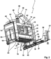
- the Figures 1 and 2 show in two different perspective views a bale opener 1 with the features of the present invention.
- the bale opener 1 is used for milling the top of fiber bales 100, which are placed in a setting-up area 28 on a floor 50 in several rows next to each other in a setting-up direction 10.
- a removal unit 12 which is mounted on a machine frame 11 so that it can move in a vertical direction, is used to mill the top of the fiber bales 100.
- the machine frame 11 has a first side wall 13 and a second side wall 14, and two portal profiles 16 arranged at a distance from one another extend between the two side walls 13 and 14.
- the side walls 13, 14 have rollers 43 and 44, and a guide rail 52 on which the rollers 43 are guided on the first side wall 13 is used to guide the machine frame 11 in the installation direction 10.
- the rollers 44 which are located on the underside of the second side wall 14, run over the floor 50, on which the fiber bales 100 are also placed, and on which the guide rail 31 is mounted.
- the collector unit 12 has two collector rollers 25 and three support rollers 32 on a bottom side, with the collector rollers 25 located between the support rollers 32, and with all rollers 25, 32 running parallel to one another in the transverse direction 15. Gratings 33 are located in front of the collector rollers 25. If the rollers 25, 32 are set in rotation, the collector rollers 26 pick up flake-like components from the pressed fiber bales 100, and the fiber flakes are sucked off via the suction device 26 and fed for further use.
- the suction device 26 comprises a suction hood 34, which is located on the top of the collector unit 12 and to which a spiral hose 35 leading vertically upwards is connected.
- a suction air shaft 36 which introduces the suction air into the top of the first side wall 13.
- the suction air shaft 36 is thus self-supporting. attached to the top of the first side wall 13, and the spiral hose 35 is arranged in a hanging arrangement at the free end of the suction air shaft 36.
- the suction air passes through the first side wall 13 and reaches a further processing station via a channel 27 together with the fiber flakes.
- the manual control of the bale opener 1 is carried out via a control panel 37, which is set up, for example, at the head end of the channel 27.
- the electrical supply to the bale opener 1 is via a connection box 38, which is located at the same head end of the channel 27.
- An electrical supply and a signal connection to the movable machine frame 11 can be established via a power and signal connection 29, comprising a cable chain unit 30, wherein the power and signal connection 29 is located on the side of the channel 27.
- a driver 39 forms the movable connection of the channel chain unit 30 and is connected to a belt lifting unit 40, which is connected to the first side cheek 13 and is consequently moved along with the movement of the machine frame 11 in the installation direction 10.
- the bath lifting unit 40 is used to lift a cover belt 45, which covers the top of the channel 27.
- Two bridge elements 51 are mounted on the two portal profiles 16 running parallel between the side walls 13, 14, on which the pickup unit 12 is suspended so that it can be moved in height by means of traction means 41.
- the pickup unit has side flaps 19 on both sides which can be opened in order to access the pickup rollers 25 and the support rollers 32, in particular for maintenance and cleaning purposes.
- a tactile switching element 18 is shown on the underside, behind which an electrical switch is arranged. If the machine frame 11 moves in the setting-up direction 10, objects lying on the floor 50 will come into contact with at least one the tactile switching elements 18, which causes an interruption in the movement of the machine frame 11.
- the tactile switching element 18 can also be used to detect people who are standing in the movement area of the side walls 13, 14.
- Fig.3 shows a perspective detailed view of the side walls 13 and 14 with the pickup unit 12 arranged between them.
- Collision sensors 17 are arranged on the side walls 13 and 14 on both sides of the installation direction 10.
- the collision sensors 17 have a sensor cone 31, and all objects detected by the collision sensors 17 lead to an interruption or slowing down of the movement of the machine frame 11 of the bale opener 1 in the installation direction 10.
- the pickup 12 has side flaps 19 arranged on both sides, which are pivotably arranged on the top of the pickup unit 12 and wherein a movement of the side flaps 19 at least into a closed position or out of a closed position can be monitored by means of a flap monitoring means 20.
- the closing direction for pivoting the side flap 19 is marked with I and the opening direction is marked with II.
- the side flap 19 can also be operated manually, in particular by means of the flap handle 49.
- the flap monitoring means 20 comprises a flap tappet 21, which can either be pressed into the flap monitoring means 20 or moved out of it, as indicated by a double arrow. In this way, a movement of the side flap 19 in the closing direction I as well as in the opening direction II can be detected.
- the flap monitoring means 20 which comprises a flap tappet 21, and the flap tappet 21 is movably received along a tappet axis 47.
- the Figure 4 The situation shown exists when the side flap 19 is normally closed.
- the flap tappet 21 is pre-tensioned with a spring element 48 such that the flap tappet 21 is in a rest position which is designed such that the side flap 19 on the pickup unit 12 remains essentially closed.
- a probe 23 of an electrical switch 24 rests on a switching contour 22 of the flap tappet 21.
- the probe 23 is arranged pre-tensioned essentially transversely to the direction of movement I, II of the flap tappet 21 in the direction of the flap tappet 21.
- the flap tappet 21 is moved in the opening direction II, so that the sensor head 23 is now actuated by the switching contour 22b due to the pre-tensioned spring 48, and the electrical switch 24 also triggers an electrical signal when the side flap 19 is opened.
- This makes it possible to detect monitoring of the side flap 19 in the event of a collision with a foreign body, whereby the side flap 19 is pressed further in the closing direction I, and opening of the side flap 19 can also be detected in the same way by moving the flap tappet 21 in the opening direction II.
- the switching signal of the electrical switch 24 for example, the travel movement of the machine frame 11 of the bale opener 1 can be interrupted and/or the at least one pickup roller 25 of the pickup unit 12 can be put out of operation.
- the invention is not limited to the preferred embodiment described above. Rather, a number of variants are conceivable which make use of the solution presented even in fundamentally different embodiments.
Landscapes
- Engineering & Computer Science (AREA)
- Textile Engineering (AREA)
- Preliminary Treatment Of Fibers (AREA)
Claims (12)
- Brise-balles (1) destiné à l'ouvraison de balles de fibres (100) comprimées et mises en place sur un sol (21) dans une direction de mise en place (10), comportant• un bâti de machine (11), qui- est disposé déplaçable dans la direction de mise en place (10) et- présente une construction en portique avec un premier panneau latéral (13) et un second panneau latéral (14) et• une unité détacheuse (12), qui- présente au moins un cylindre détacheur (26),- est disposée sur le bâti de machine (11) de manière réglable en hauteur et- est configurée pour passer au-dessus des balles de fibres lors du déplacement du bâti de machine (11) pour détacher des fibres des balles de fibres (100) au moyen de l'au moins un cylindre détacheur (26),• dans lequel les panneaux latéraux (13, 14) sont reliés l'un à l'autre au moyen d'au moins un profilé de portique (16) s'étendant dans une direction transversale (15), transversalement à la direction de mise en place et parallèlement au sol (21)
caractérisé en ce que• un capteur de collision (17) orienté dans l'une des directions de mouvement du bâti de machine (11) est disposé respectivement sur le premier panneau latéral (13) et sur le second panneau latéral (14), dans lequel• les capteurs de collision (17) sont réalisés sous la forme de détecteurs optiques à réflexion et• une surveillance de collision du bâti de machine (11) peut être exécutée au moyen des capteurs de collision (17) indépendamment de l'état de fonctionnement des cylindres détacheurs (26). - Brise-balles (1) selon la revendication 1, caractérisé en ce que les capteurs de collision (17)• présentent, sur le panneau latéral (13, 14) associé respectif, une étendue de détection de 500 mm à 1000 mm et/ou de 600 mm à 800 mm.
- Brise-balles (1) selon l'une des revendications précédentes, caractérisé en ce que• l'unité détacheuse (12) présente deux volets latéraux (19) orientés chacun dans l'une des directions de mouvement, lesquels sont disposés sur l'unité détacheuse (12) de manière mobile dans une direction d'ouverture (II) et une direction de fermeture (I), et• un moyen de surveillance de volet (20), configuré pour surveiller un mouvement d'un volet latéral (19) associé au moins entrant dans une position de fermeture ou sortant d'une position de fermeture.
- Brise-balles (1) selon la revendication 3, caractérisé en ce qu'au moins un volet latéral (19) est disposé de manière pivotante.
- Brise-balles (1) selon la revendication 4, caractérisé en ce que l'au moins un volet latéral (19) est disposé de manière pivotante sur le côté supérieur de l'unité détacheuse (12).
- Brise-balles (1) selon l'une des revendications 3 à 5, caractérisé en ce que• le moyen de surveillance de volet (20) présente une tige-poussoir de volet (21) et• la tige-poussoir de volet (21) et le volet latéral (19) associé sont disposés de telle manière que la tige-poussoir de volet (21) vient en contact contre le volet latéral (19) quand celui-ci est déplacé dans une position de fermeture.
- Brise-balles (1) selon la revendication 6, caractérisé en ce que la tige-poussoir de volet (21) présente un contour de commutation (22, 22a, 22b) contre lequel est guidée une tête palpeuse (23) d'un commutateur électrique (24).
- Brise-balles (1) selon la revendication 7, caractérisé en ce que le contour de commutation (22a, 22b) est conçu de telle manière que le commutateur électrique (24) est déclenché, l'amenant à sortir d'une position de fermeture du volet latéral (19),• lors d'un enfoncement de la tige-poussoir de volet (21) dans la direction de fermeture (I) du volet latéral (19) et• lors d'une sortie de la tige-poussoir de volet (21) dans une direction d'ouverture (II), opposée à la direction de fermeture, du volet latéral (19).
- Brise-balles (1) selon l'une des revendications précédentes, caractérisé par un élément de commutation (18) tactile disposé sur les panneaux latéraux (13, 14) dans une zone proche du sol et orienté respectivement dans l'une des directions de mouvement du bâti de machine (11).
- Procédé de commande d'un système de protection d'un brise-balles (1) selon l'une des revendications précédentes, caractérisé par une étape de sécurité consistant à ralentir, arrêter ou inverser au moins le mouvement de déplacement du bâti de machine (11) et/ou arrêter ou partiellement inverser et arrêter l'au moins un cylindre détacheur (26) quand au moins un capteur de collision (17) situé sur les panneaux latéraux (13, 14) détecte un corps étranger.
- Procédé selon la revendication 10, caractérisé en ce que• le brise-balles est réalisé selon la revendication 9 et• l'étape de sécurité est exécutée quand l'un des éléments de commutation (18) tactiles situés sur les panneaux latéraux (13, 14) est déclenché.
- Procédé selon la revendication 10 ou 11, caractérisé en ce que• le brise-balles est réalisé selon la revendication 7 ou 8 et• l'étape de sécurité est exécutée quand le commutateur électrique (24) du moyen de surveillance de volet (20) se déclenche.
Applications Claiming Priority (2)
| Application Number | Priority Date | Filing Date | Title |
|---|---|---|---|
| DE102018110669.6A DE102018110669A1 (de) | 2018-05-04 | 2018-05-04 | Ballenöffner zum Öffnen von gepressten Faserballen mit einem Kollisionsschutzsystem |
| PCT/EP2019/053023 WO2019211017A1 (fr) | 2018-05-04 | 2019-02-07 | Brise-balles destiné à l'ouvraison de balles de fibres comprimées, doté d'un système de protection contre les collisions |
Publications (2)
| Publication Number | Publication Date |
|---|---|
| EP3788189A1 EP3788189A1 (fr) | 2021-03-10 |
| EP3788189B1 true EP3788189B1 (fr) | 2024-08-28 |
Family
ID=65520227
Family Applications (1)
| Application Number | Title | Priority Date | Filing Date |
|---|---|---|---|
| EP19706904.0A Active EP3788189B1 (fr) | 2018-05-04 | 2019-02-07 | Brise-balles destiné à l'ouvraison de balles de fibres comprimées, doté d'un système de protection contre les collisions |
Country Status (4)
| Country | Link |
|---|---|
| EP (1) | EP3788189B1 (fr) |
| CN (1) | CN112055762B (fr) |
| DE (1) | DE102018110669A1 (fr) |
| WO (1) | WO2019211017A1 (fr) |
Family Cites Families (14)
| Publication number | Priority date | Publication date | Assignee | Title |
|---|---|---|---|---|
| DE3135272C2 (de) * | 1981-09-05 | 1986-10-09 | Trützschler GmbH & Co KG, 4050 Mönchengladbach | Verfahren und Vorrichtung zur Ermittlung der Höhe von Textilfaserballen |
| US4507826A (en) * | 1982-10-13 | 1985-04-02 | Keller Alex J | Method and apparatus for opening fiber bales |
| DE3637578A1 (de) * | 1986-11-04 | 1988-05-11 | Schubert & Salzer Maschinen | Vorrichtung zum selbsttaetigen oeffnen und mischen von faserballen |
| DE3734480A1 (de) | 1987-10-12 | 1989-04-27 | Schubert & Salzer Maschinen | Verfahren und vorrichtung zum oeffnen von faserballen |
| DE59002045D1 (de) * | 1989-01-16 | 1993-09-02 | Rieter Ag Maschf | Ballenabtragmaschine mit einer sicherheitseinrichtung. |
| CH680514A5 (fr) * | 1989-11-13 | 1992-09-15 | Rieter Ag Maschf | |
| EP0435816A1 (fr) | 1989-12-21 | 1991-07-03 | Maschinenfabrik Rieter Ag | Ouvreuse de balles avec un appareil de sécurité commandé par un détecteur |
| EP0533619B1 (fr) | 1991-09-19 | 1996-09-25 | Maschinenfabrik Rieter Ag | Appareil de sécurité sur une pièce de machine mobile d'une machine textile |
| DE102007014612A1 (de) * | 2007-03-23 | 2008-09-25 | TRüTZSCHLER GMBH & CO. KG | Vorrichtung zur Überwachung und Sicherung von Gefahrenbereichen an kraftgetriebenen Textilmaschinen, insbesondere Spinnereivorbereitungsmaschinen |
| DE102007051466A1 (de) * | 2007-10-27 | 2009-04-30 | Rafi Gmbh & Co. Kg | Schaltvorrichtung |
| US8207805B2 (en) * | 2009-03-17 | 2012-06-26 | W. Gessmann Gmbh | Push-button |
| DE102012004071A1 (de) * | 2012-03-02 | 2013-09-05 | Illinois Tool Works Inc. | Betätigungsvorrichtung |
| CN104726968B (zh) * | 2015-04-02 | 2016-10-12 | 安徽华茂纺织股份有限公司 | 一种圆盘抓棉机的安全防撞击装置 |
| CH712410A1 (de) * | 2016-04-29 | 2017-10-31 | Rieter Ag Maschf | Ballenöffner. |
-
2018
- 2018-05-04 DE DE102018110669.6A patent/DE102018110669A1/de not_active Withdrawn
-
2019
- 2019-02-07 CN CN201980029507.0A patent/CN112055762B/zh active Active
- 2019-02-07 EP EP19706904.0A patent/EP3788189B1/fr active Active
- 2019-02-07 WO PCT/EP2019/053023 patent/WO2019211017A1/fr not_active Ceased
Also Published As
| Publication number | Publication date |
|---|---|
| WO2019211017A1 (fr) | 2019-11-07 |
| CN112055762A (zh) | 2020-12-08 |
| EP3788189A1 (fr) | 2021-03-10 |
| CN112055762B (zh) | 2022-11-11 |
| DE102018110669A1 (de) | 2019-11-07 |
Similar Documents
| Publication | Publication Date | Title |
|---|---|---|
| EP0902158B1 (fr) | Dispositif de sécurité pour dispositifs entraínés par moteur | |
| EP0902157B1 (fr) | Porte entraínée par un moteur avec dispositif de sécurité | |
| EP2404859B1 (fr) | Dispositif de surveillance pour sécuriser un élément entraîné | |
| EP2346762B1 (fr) | Protection de zone de danger pour la zone de garnissage automatique sur un changeur de bobine | |
| DE102010017398B3 (de) | Verfahren zum Betrieb eines Tores sowie Vorrichtung zum Betrieb eines Tores | |
| DE102013203547B4 (de) | Roboterarbeitsplatzanordnung und Verfahren zum Betreiben der Roboterarbeitsplatzanordnung | |
| EP3660251B1 (fr) | Dispositif de protection, en particulier portail industriel | |
| EP0379465B1 (fr) | Ouvreuse de balles avec un dispositif de sécurité | |
| EP3788189B1 (fr) | Brise-balles destiné à l'ouvraison de balles de fibres comprimées, doté d'un système de protection contre les collisions | |
| DE4313475C2 (de) | Fahrbühne für das Bedienungspersonal eines Kalanders | |
| EP2354415B1 (fr) | Porte sectionnelle | |
| DE202014005758U1 (de) | Schutzvorrichtung für Aufzüge | |
| EP3239367B1 (fr) | Procédé de fonctionnement d'un brise-balles et brise-balles | |
| EP2444585A2 (fr) | Procédé de surveillance de mouvements sur un portail roulant et dispositif d'exécution du procédé | |
| EP4288318B1 (fr) | Système d'embarquement ayant un marchepied coulissant et un joint d'étanchéité actif | |
| EP3106738A1 (fr) | Dispositif destine a deplacer et a arreter une porte | |
| DE102018110697A1 (de) | Ballenöffner zum Öffnen von gepressten Faserballen mit einem Schutzsystem und Verfahren zur Steuerung eines Schutzsystems für einen Ballenöffner | |
| EP2402543B1 (fr) | Portail roulant et procédé de détermination d'un état de charge indésirable par ce type de portail roulant | |
| EP0428477A1 (fr) | Ouvreuse de balles avec un dispositif de sécurité sensoriel | |
| DE202006002000U1 (de) | Tor mit Lichtschrankenanordnung | |
| EP0764758B1 (fr) | Porte enroulable avec une grille | |
| EP1931747B1 (fr) | Machine de manipulation pour four a coke, pourvue d'un dispositif d'aspiration destine a aspirer des emissions | |
| EP0671532A1 (fr) | Système de fermeture à grande vitesse | |
| AT527917B1 (de) | Spaltvorrichtung zum Spalten von Holz | |
| DE102006055243B4 (de) | Schutztürsystem und Verfahren zum Schließen bzw. Öffnen |
Legal Events
| Date | Code | Title | Description |
|---|---|---|---|
| STAA | Information on the status of an ep patent application or granted ep patent |
Free format text: STATUS: UNKNOWN |
|
| STAA | Information on the status of an ep patent application or granted ep patent |
Free format text: STATUS: THE INTERNATIONAL PUBLICATION HAS BEEN MADE |
|
| PUAI | Public reference made under article 153(3) epc to a published international application that has entered the european phase |
Free format text: ORIGINAL CODE: 0009012 |
|
| STAA | Information on the status of an ep patent application or granted ep patent |
Free format text: STATUS: REQUEST FOR EXAMINATION WAS MADE |
|
| 17P | Request for examination filed |
Effective date: 20201110 |
|
| AK | Designated contracting states |
Kind code of ref document: A1 Designated state(s): AL AT BE BG CH CY CZ DE DK EE ES FI FR GB GR HR HU IE IS IT LI LT LU LV MC MK MT NL NO PL PT RO RS SE SI SK SM TR |
|
| AX | Request for extension of the european patent |
Extension state: BA ME |
|
| DAV | Request for validation of the european patent (deleted) | ||
| DAX | Request for extension of the european patent (deleted) | ||
| RAP1 | Party data changed (applicant data changed or rights of an application transferred) |
Owner name: TRUETZSCHLER GROUP SE |
|
| STAA | Information on the status of an ep patent application or granted ep patent |
Free format text: STATUS: EXAMINATION IS IN PROGRESS |
|
| 17Q | First examination report despatched |
Effective date: 20221017 |
|
| P01 | Opt-out of the competence of the unified patent court (upc) registered |
Effective date: 20230622 |
|
| REG | Reference to a national code |
Ref country code: DE Ref legal event code: R079 Free format text: PREVIOUS MAIN CLASS: D01G0007120000 Ipc: D01G0007040000 Ref country code: DE Ref legal event code: R079 Ref document number: 502019011985 Country of ref document: DE Free format text: PREVIOUS MAIN CLASS: D01G0007120000 Ipc: D01G0007040000 |
|
| RIC1 | Information provided on ipc code assigned before grant |
Ipc: D01G 7/04 20060101AFI20240208BHEP |
|
| GRAP | Despatch of communication of intention to grant a patent |
Free format text: ORIGINAL CODE: EPIDOSNIGR1 |
|
| STAA | Information on the status of an ep patent application or granted ep patent |
Free format text: STATUS: GRANT OF PATENT IS INTENDED |
|
| INTG | Intention to grant announced |
Effective date: 20240409 |
|
| GRAS | Grant fee paid |
Free format text: ORIGINAL CODE: EPIDOSNIGR3 |
|
| GRAA | (expected) grant |
Free format text: ORIGINAL CODE: 0009210 |
|
| STAA | Information on the status of an ep patent application or granted ep patent |
Free format text: STATUS: THE PATENT HAS BEEN GRANTED |
|
| AK | Designated contracting states |
Kind code of ref document: B1 Designated state(s): AL AT BE BG CH CY CZ DE DK EE ES FI FR GB GR HR HU IE IS IT LI LT LU LV MC MK MT NL NO PL PT RO RS SE SI SK SM TR |
|
| REG | Reference to a national code |
Ref country code: GB Ref legal event code: FG4D Free format text: NOT ENGLISH |
|
| REG | Reference to a national code |
Ref country code: CH Ref legal event code: EP |
|
| REG | Reference to a national code |
Ref country code: DE Ref legal event code: R096 Ref document number: 502019011985 Country of ref document: DE |
|
| REG | Reference to a national code |
Ref country code: IE Ref legal event code: FG4D Free format text: LANGUAGE OF EP DOCUMENT: GERMAN |
|
| REG | Reference to a national code |
Ref country code: LT Ref legal event code: MG9D |
|
| PG25 | Lapsed in a contracting state [announced via postgrant information from national office to epo] |
Ref country code: NO Free format text: LAPSE BECAUSE OF FAILURE TO SUBMIT A TRANSLATION OF THE DESCRIPTION OR TO PAY THE FEE WITHIN THE PRESCRIBED TIME-LIMIT Effective date: 20241128 |
|
| PG25 | Lapsed in a contracting state [announced via postgrant information from national office to epo] |
Ref country code: NL Free format text: LAPSE BECAUSE OF FAILURE TO SUBMIT A TRANSLATION OF THE DESCRIPTION OR TO PAY THE FEE WITHIN THE PRESCRIBED TIME-LIMIT Effective date: 20240828 Ref country code: GR Free format text: LAPSE BECAUSE OF FAILURE TO SUBMIT A TRANSLATION OF THE DESCRIPTION OR TO PAY THE FEE WITHIN THE PRESCRIBED TIME-LIMIT Effective date: 20241129 Ref country code: PL Free format text: LAPSE BECAUSE OF FAILURE TO SUBMIT A TRANSLATION OF THE DESCRIPTION OR TO PAY THE FEE WITHIN THE PRESCRIBED TIME-LIMIT Effective date: 20240828 Ref country code: FI Free format text: LAPSE BECAUSE OF FAILURE TO SUBMIT A TRANSLATION OF THE DESCRIPTION OR TO PAY THE FEE WITHIN THE PRESCRIBED TIME-LIMIT Effective date: 20240828 Ref country code: PT Free format text: LAPSE BECAUSE OF FAILURE TO SUBMIT A TRANSLATION OF THE DESCRIPTION OR TO PAY THE FEE WITHIN THE PRESCRIBED TIME-LIMIT Effective date: 20241230 |
|
| PG25 | Lapsed in a contracting state [announced via postgrant information from national office to epo] |
Ref country code: BG Free format text: LAPSE BECAUSE OF FAILURE TO SUBMIT A TRANSLATION OF THE DESCRIPTION OR TO PAY THE FEE WITHIN THE PRESCRIBED TIME-LIMIT Effective date: 20240828 |
|
| PG25 | Lapsed in a contracting state [announced via postgrant information from national office to epo] |
Ref country code: LV Free format text: LAPSE BECAUSE OF FAILURE TO SUBMIT A TRANSLATION OF THE DESCRIPTION OR TO PAY THE FEE WITHIN THE PRESCRIBED TIME-LIMIT Effective date: 20240828 |
|
| REG | Reference to a national code |
Ref country code: NL Ref legal event code: MP Effective date: 20240828 |
|
| PG25 | Lapsed in a contracting state [announced via postgrant information from national office to epo] |
Ref country code: IS Free format text: LAPSE BECAUSE OF FAILURE TO SUBMIT A TRANSLATION OF THE DESCRIPTION OR TO PAY THE FEE WITHIN THE PRESCRIBED TIME-LIMIT Effective date: 20241228 |
|
| PG25 | Lapsed in a contracting state [announced via postgrant information from national office to epo] |
Ref country code: HR Free format text: LAPSE BECAUSE OF FAILURE TO SUBMIT A TRANSLATION OF THE DESCRIPTION OR TO PAY THE FEE WITHIN THE PRESCRIBED TIME-LIMIT Effective date: 20240828 |
|
| PG25 | Lapsed in a contracting state [announced via postgrant information from national office to epo] |
Ref country code: ES Free format text: LAPSE BECAUSE OF FAILURE TO SUBMIT A TRANSLATION OF THE DESCRIPTION OR TO PAY THE FEE WITHIN THE PRESCRIBED TIME-LIMIT Effective date: 20240828 Ref country code: RS Free format text: LAPSE BECAUSE OF FAILURE TO SUBMIT A TRANSLATION OF THE DESCRIPTION OR TO PAY THE FEE WITHIN THE PRESCRIBED TIME-LIMIT Effective date: 20241128 |
|
| PG25 | Lapsed in a contracting state [announced via postgrant information from national office to epo] |
Ref country code: RS Free format text: LAPSE BECAUSE OF FAILURE TO SUBMIT A TRANSLATION OF THE DESCRIPTION OR TO PAY THE FEE WITHIN THE PRESCRIBED TIME-LIMIT Effective date: 20241128 Ref country code: PT Free format text: LAPSE BECAUSE OF FAILURE TO SUBMIT A TRANSLATION OF THE DESCRIPTION OR TO PAY THE FEE WITHIN THE PRESCRIBED TIME-LIMIT Effective date: 20241230 Ref country code: PL Free format text: LAPSE BECAUSE OF FAILURE TO SUBMIT A TRANSLATION OF THE DESCRIPTION OR TO PAY THE FEE WITHIN THE PRESCRIBED TIME-LIMIT Effective date: 20240828 Ref country code: NO Free format text: LAPSE BECAUSE OF FAILURE TO SUBMIT A TRANSLATION OF THE DESCRIPTION OR TO PAY THE FEE WITHIN THE PRESCRIBED TIME-LIMIT Effective date: 20241128 Ref country code: NL Free format text: LAPSE BECAUSE OF FAILURE TO SUBMIT A TRANSLATION OF THE DESCRIPTION OR TO PAY THE FEE WITHIN THE PRESCRIBED TIME-LIMIT Effective date: 20240828 Ref country code: LV Free format text: LAPSE BECAUSE OF FAILURE TO SUBMIT A TRANSLATION OF THE DESCRIPTION OR TO PAY THE FEE WITHIN THE PRESCRIBED TIME-LIMIT Effective date: 20240828 Ref country code: IS Free format text: LAPSE BECAUSE OF FAILURE TO SUBMIT A TRANSLATION OF THE DESCRIPTION OR TO PAY THE FEE WITHIN THE PRESCRIBED TIME-LIMIT Effective date: 20241228 Ref country code: HR Free format text: LAPSE BECAUSE OF FAILURE TO SUBMIT A TRANSLATION OF THE DESCRIPTION OR TO PAY THE FEE WITHIN THE PRESCRIBED TIME-LIMIT Effective date: 20240828 Ref country code: GR Free format text: LAPSE BECAUSE OF FAILURE TO SUBMIT A TRANSLATION OF THE DESCRIPTION OR TO PAY THE FEE WITHIN THE PRESCRIBED TIME-LIMIT Effective date: 20241129 Ref country code: FI Free format text: LAPSE BECAUSE OF FAILURE TO SUBMIT A TRANSLATION OF THE DESCRIPTION OR TO PAY THE FEE WITHIN THE PRESCRIBED TIME-LIMIT Effective date: 20240828 Ref country code: ES Free format text: LAPSE BECAUSE OF FAILURE TO SUBMIT A TRANSLATION OF THE DESCRIPTION OR TO PAY THE FEE WITHIN THE PRESCRIBED TIME-LIMIT Effective date: 20240828 Ref country code: BG Free format text: LAPSE BECAUSE OF FAILURE TO SUBMIT A TRANSLATION OF THE DESCRIPTION OR TO PAY THE FEE WITHIN THE PRESCRIBED TIME-LIMIT Effective date: 20240828 |
|
| PG25 | Lapsed in a contracting state [announced via postgrant information from national office to epo] |
Ref country code: SM Free format text: LAPSE BECAUSE OF FAILURE TO SUBMIT A TRANSLATION OF THE DESCRIPTION OR TO PAY THE FEE WITHIN THE PRESCRIBED TIME-LIMIT Effective date: 20240828 Ref country code: RO Free format text: LAPSE BECAUSE OF FAILURE TO SUBMIT A TRANSLATION OF THE DESCRIPTION OR TO PAY THE FEE WITHIN THE PRESCRIBED TIME-LIMIT Effective date: 20240828 Ref country code: DK Free format text: LAPSE BECAUSE OF FAILURE TO SUBMIT A TRANSLATION OF THE DESCRIPTION OR TO PAY THE FEE WITHIN THE PRESCRIBED TIME-LIMIT Effective date: 20240828 |
|
| PG25 | Lapsed in a contracting state [announced via postgrant information from national office to epo] |
Ref country code: EE Free format text: LAPSE BECAUSE OF FAILURE TO SUBMIT A TRANSLATION OF THE DESCRIPTION OR TO PAY THE FEE WITHIN THE PRESCRIBED TIME-LIMIT Effective date: 20240828 |
|
| PGFP | Annual fee paid to national office [announced via postgrant information from national office to epo] |
Ref country code: CH Payment date: 20250301 Year of fee payment: 7 |
|
| PG25 | Lapsed in a contracting state [announced via postgrant information from national office to epo] |
Ref country code: CZ Free format text: LAPSE BECAUSE OF FAILURE TO SUBMIT A TRANSLATION OF THE DESCRIPTION OR TO PAY THE FEE WITHIN THE PRESCRIBED TIME-LIMIT Effective date: 20240828 |
|
| PG25 | Lapsed in a contracting state [announced via postgrant information from national office to epo] |
Ref country code: SK Free format text: LAPSE BECAUSE OF FAILURE TO SUBMIT A TRANSLATION OF THE DESCRIPTION OR TO PAY THE FEE WITHIN THE PRESCRIBED TIME-LIMIT Effective date: 20240828 |
|
| REG | Reference to a national code |
Ref country code: DE Ref legal event code: R097 Ref document number: 502019011985 Country of ref document: DE |
|
| PLBE | No opposition filed within time limit |
Free format text: ORIGINAL CODE: 0009261 |
|
| STAA | Information on the status of an ep patent application or granted ep patent |
Free format text: STATUS: NO OPPOSITION FILED WITHIN TIME LIMIT |
|
| 26N | No opposition filed |
Effective date: 20250530 |
|
| PG25 | Lapsed in a contracting state [announced via postgrant information from national office to epo] |
Ref country code: SE Free format text: LAPSE BECAUSE OF FAILURE TO SUBMIT A TRANSLATION OF THE DESCRIPTION OR TO PAY THE FEE WITHIN THE PRESCRIBED TIME-LIMIT Effective date: 20240828 |
|
| PG25 | Lapsed in a contracting state [announced via postgrant information from national office to epo] |
Ref country code: MC Free format text: LAPSE BECAUSE OF FAILURE TO SUBMIT A TRANSLATION OF THE DESCRIPTION OR TO PAY THE FEE WITHIN THE PRESCRIBED TIME-LIMIT Effective date: 20240828 |
|
| PG25 | Lapsed in a contracting state [announced via postgrant information from national office to epo] |
Ref country code: LU Free format text: LAPSE BECAUSE OF NON-PAYMENT OF DUE FEES Effective date: 20250207 |
|
| GBPC | Gb: european patent ceased through non-payment of renewal fee |
Effective date: 20250207 |
|
| REG | Reference to a national code |
Ref country code: BE Ref legal event code: MM Effective date: 20250228 |
|
| PG25 | Lapsed in a contracting state [announced via postgrant information from national office to epo] |
Ref country code: GB Free format text: LAPSE BECAUSE OF NON-PAYMENT OF DUE FEES Effective date: 20250207 |
|
| PG25 | Lapsed in a contracting state [announced via postgrant information from national office to epo] |
Ref country code: FR Free format text: LAPSE BECAUSE OF NON-PAYMENT OF DUE FEES Effective date: 20250228 |
|
| PG25 | Lapsed in a contracting state [announced via postgrant information from national office to epo] |
Ref country code: BE Free format text: LAPSE BECAUSE OF NON-PAYMENT OF DUE FEES Effective date: 20250228 |
|
| PG25 | Lapsed in a contracting state [announced via postgrant information from national office to epo] |
Ref country code: IE Free format text: LAPSE BECAUSE OF NON-PAYMENT OF DUE FEES Effective date: 20250207 |
|
| REG | Reference to a national code |
Ref country code: CH Ref legal event code: U11 Free format text: ST27 STATUS EVENT CODE: U-0-0-U10-U11 (AS PROVIDED BY THE NATIONAL OFFICE) Effective date: 20260301 |
|
| PGFP | Annual fee paid to national office [announced via postgrant information from national office to epo] |
Ref country code: DE Payment date: 20260218 Year of fee payment: 8 |
|
| PG25 | Lapsed in a contracting state [announced via postgrant information from national office to epo] |
Ref country code: AT Free format text: LAPSE BECAUSE OF NON-PAYMENT OF DUE FEES Effective date: 20250207 |
|
| PGFP | Annual fee paid to national office [announced via postgrant information from national office to epo] |
Ref country code: IT Payment date: 20260224 Year of fee payment: 8 |
|
| REG | Reference to a national code |
Ref country code: AT Ref legal event code: MM01 Ref document number: 1718048 Country of ref document: AT Kind code of ref document: T Effective date: 20250207 |