EP3788751B1 - Randomiseur de symboles de modulation en tout-ou-rien multiporteuse - Google Patents
Randomiseur de symboles de modulation en tout-ou-rien multiporteuse Download PDFInfo
- Publication number
- EP3788751B1 EP3788751B1 EP19725801.5A EP19725801A EP3788751B1 EP 3788751 B1 EP3788751 B1 EP 3788751B1 EP 19725801 A EP19725801 A EP 19725801A EP 3788751 B1 EP3788751 B1 EP 3788751B1
- Authority
- EP
- European Patent Office
- Prior art keywords
- random
- modulation symbol
- pseudorandom
- symbol
- sequence
- Prior art date
- Legal status (The legal status is an assumption and is not a legal conclusion. Google has not performed a legal analysis and makes no representation as to the accuracy of the status listed.)
- Active
Links
Images




Classifications
-
- H—ELECTRICITY
- H04—ELECTRIC COMMUNICATION TECHNIQUE
- H04L—TRANSMISSION OF DIGITAL INFORMATION, e.g. TELEGRAPHIC COMMUNICATION
- H04L27/00—Modulated-carrier systems
- H04L27/02—Amplitude-modulated carrier systems, e.g. using on-off keying; Single sideband or vestigial sideband modulation
- H04L27/04—Modulator circuits; Transmitter circuits
-
- H—ELECTRICITY
- H04—ELECTRIC COMMUNICATION TECHNIQUE
- H04L—TRANSMISSION OF DIGITAL INFORMATION, e.g. TELEGRAPHIC COMMUNICATION
- H04L27/00—Modulated-carrier systems
- H04L27/26—Systems using multi-frequency codes
- H04L27/2601—Multicarrier modulation systems
- H04L27/2626—Arrangements specific to the transmitter only
- H04L27/2627—Modulators
-
- H—ELECTRICITY
- H04—ELECTRIC COMMUNICATION TECHNIQUE
- H04L—TRANSMISSION OF DIGITAL INFORMATION, e.g. TELEGRAPHIC COMMUNICATION
- H04L27/00—Modulated-carrier systems
- H04L27/32—Carrier systems characterised by combinations of two or more of the types covered by groups H04L27/02, H04L27/10, H04L27/18 or H04L27/26
- H04L27/34—Amplitude- and phase-modulated carrier systems, e.g. quadrature-amplitude modulated carrier systems
- H04L27/36—Modulator circuits; Transmitter circuits
- H04L27/361—Modulation using a single or unspecified number of carriers, e.g. with separate stages of phase and amplitude modulation
-
- H—ELECTRICITY
- H04—ELECTRIC COMMUNICATION TECHNIQUE
- H04L—TRANSMISSION OF DIGITAL INFORMATION, e.g. TELEGRAPHIC COMMUNICATION
- H04L5/00—Arrangements affording multiple use of the transmission path
- H04L5/0001—Arrangements for dividing the transmission path
- H04L5/0003—Two-dimensional division
- H04L5/0005—Time-frequency
- H04L5/0007—Time-frequency the frequencies being orthogonal, e.g. OFDM(A) or DMT
-
- H—ELECTRICITY
- H04—ELECTRIC COMMUNICATION TECHNIQUE
- H04W—WIRELESS COMMUNICATION NETWORKS
- H04W52/00—Power management, e.g. Transmission Power Control [TPC] or power classes
- H04W52/02—Power saving arrangements
- H04W52/0209—Power saving arrangements in terminal devices
- H04W52/0212—Power saving arrangements in terminal devices managed by the network, e.g. network or access point is leader and terminal is follower
-
- H—ELECTRICITY
- H04—ELECTRIC COMMUNICATION TECHNIQUE
- H04L—TRANSMISSION OF DIGITAL INFORMATION, e.g. TELEGRAPHIC COMMUNICATION
- H04L27/00—Modulated-carrier systems
- H04L27/18—Phase-modulated carrier systems, i.e. using phase-shift keying
- H04L27/20—Modulator circuits; Transmitter circuits
-
- H—ELECTRICITY
- H04—ELECTRIC COMMUNICATION TECHNIQUE
- H04L—TRANSMISSION OF DIGITAL INFORMATION, e.g. TELEGRAPHIC COMMUNICATION
- H04L5/00—Arrangements affording multiple use of the transmission path
- H04L5/0001—Arrangements for dividing the transmission path
- H04L5/0003—Two-dimensional division
- H04L5/0005—Time-frequency
-
- Y—GENERAL TAGGING OF NEW TECHNOLOGICAL DEVELOPMENTS; GENERAL TAGGING OF CROSS-SECTIONAL TECHNOLOGIES SPANNING OVER SEVERAL SECTIONS OF THE IPC; TECHNICAL SUBJECTS COVERED BY FORMER USPC CROSS-REFERENCE ART COLLECTIONS [XRACs] AND DIGESTS
- Y02—TECHNOLOGIES OR APPLICATIONS FOR MITIGATION OR ADAPTATION AGAINST CLIMATE CHANGE
- Y02D—CLIMATE CHANGE MITIGATION TECHNOLOGIES IN INFORMATION AND COMMUNICATION TECHNOLOGIES [ICT], I.E. INFORMATION AND COMMUNICATION TECHNOLOGIES AIMING AT THE REDUCTION OF THEIR OWN ENERGY USE
- Y02D30/00—Reducing energy consumption in communication networks
- Y02D30/70—Reducing energy consumption in communication networks in wireless communication networks
Definitions
- the following relates generally to wireless communications, and more specifically to multicarrier on-off keying symbol randomizer.
- Wireless communications systems are widely deployed to provide various types of communication content such as voice, video, packet data, messaging, broadcast, and so on. These systems may be multiple-access systems capable of supporting communication with multiple users by sharing the available system resources (e.g., time, frequency, and power).
- a wireless network for example a WLAN, such as a Wi-Fi (i.e., Institute of Electrical and Electronics Engineers (IEEE) 802.11) network may include a first wireless device (e.g., an access point (AP)) that may communicate with one or more second wireless devices (e.g., stations (STAs) or mobile devices).
- the AP may be coupled to a network, such as the Internet, and may enable a mobile device to communicate via the network (or communicate with other devices coupled to the access point).
- a wireless device may communicate with a network device bi-directionally.
- a wireless station STA may communicate with an associated AP via downlink (DL) and uplink (UL).
- DL downlink
- UL uplink
- the DL (or forward link) may refer to the communication link from the AP to the station
- the UL or reverse link
- the communication link from the station to the AP may refer to the communication link from the station to the AP.
- information may be transmitted from one wireless device to another wireless device in a wireless communications system using on-off keying.
- on-off keying the information is indicated based on the presence or absence of a signal during each symbol. For example, the presence of the signal during a particular symbol may indicate a binary "1", while the absence of the signal during the symbol indicates a "0".
- US2016/269054 relates to signal quality measurement for device-to-device communication, comprising measuring power of a Device-to-Device (D2D) signal used by the wireless device for D2D operation; determining a power difference between the measured power of the D2D signal and a physical Device-to-Device Synchronization Signal (D2DSS); estimating power of a D2DSS using the measured power of the D2D signal and the determined power difference; and performing a D2D operation using the estimated power of the D2DSS.
- D2D Device-to-Device
- D2DSS Device-to-Device Synchronization Signal
- On Symbol Generation by Steve Shellhammer, vol 802.11ba, no2, 29 March 2018 , relates to On Symbold generation of 2 ⁇ s MC-OOK 'On' Symbols and 4 ⁇ s MC-OOK 'On' Symbols in wireless communications.
- the described techniques relate to improved methods, systems, devices, or apparatuses that support multicarrier on-off keying symbol randomizer.
- the described techniques provide for randomizing modulation symbol waveforms over an on-off keying sequence.
- a first wireless device e.g., an access point (AP)
- AP access point
- WUR wake-up radio
- the AP may assign a modulation symbol from a set of possible modulation symbol waveforms to at least each on symbol in the sequence.
- the modulation symbol waveforms may be assigned to sequential on symbols in a random or pseudorandom order, e.g., by applying a random phase rotation to a stored modulation symbol waveform for each on symbol, by applying a random cyclic shift to a stored modulation symbol waveform for each on symbol, or by applying a random or pseudorandom phase-shift keying value to each subcarrier in a multicarrier system to generate a modulation symbol waveform for each on symbol.
- the AP may transmit the sequence to the WUR based at least in part on the assigned modulation symbol waveforms.
- On-off keying may be used for transmitting information in a wireless communications system. Because the information is indicated by the presence or absence of a waveform during a particular symbol, the exact structure of the waveform itself may be irrelevant to whether the receiving device understands the message. As such, some wireless devices may use a single waveform for each on symbol.
- the waveform when the same waveform is used for each on symbol, the waveform may have strong autocorrelation values at the spacing of the symbol duration, or of multiples thereof. Such autocorrelation may lead to spectral lines in the power spectral density, which can in turn lead to significant power in a narrow bandwidth.
- the use of such high power in a narrow bandwidth may pose regulatory issues, because some regulators have limits on the amount of power within a narrow bandwidth.
- a wireless device may assign modulation symbol waveforms from a set of possible modulation symbol waveforms to at least each on symbol in the sequence.
- the modulation symbol waveforms may be assigned to sequential on symbols in a random or pseudorandom order such that autocorrelation may be mitigated.
- the wireless device may assign modulation symbol waveforms from a set of possible modulation symbol waveforms by applying a random or pseudorandom phase rotation to a stored modulation symbol waveform. In some other examples, the wireless device may assign modulation symbol waveforms from a set of possible modulation symbol waveforms by applying a random or pseudorandom cyclic shift to a stored modulation symbol waveform.
- the random or pseudorandom phase rotation or cyclic shift may be determined based at least in part on a random or pseudorandom number (e.g., a random or pseudorandom bit or string of bits).
- the random or pseudorandom number may be generated by a random number generator (e.g., a linear feedback shift register).
- the wireless device may assign modulation symbol waveforms from a set of possible modulation symbol waveforms by applying a random or pseudorandom phase-shift keying value to each of a plurality of subcarriers of a multicarrier system.
- the resulting modulation symbol waveform may be used for the on symbol.
- the modulation symbol waveform may be an orthogonal frequency division multiplexing (OFDM) symbol waveform
- the random or pseudorandom phase-shift keying value may be a binary phase-shift keying (BPSK) value or a quadrature phase-shift keying (QPSK) value.
- aspects of the disclosure are initially described in the context of a wireless communications system. Aspects of the disclosure are further illustrated by and described with reference to apparatus diagrams, system diagrams, and flowcharts that relate to multicarrier on-off keying symbol randomizer.
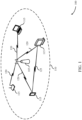
- FIG. 1 illustrates a wireless communications system 100 (also known as a Wi-Fi network) configured in accordance with various aspects of the present disclosure.
- the wireless communications system 100 e.g. wireless local area network (WLAN)
- the wireless communications system 100 may include a first wireless device (e.g., an AP 105) and multiple associated wireless devices (e.g., stations (STAs) 115, which may represent devices such as mobile stations, personal digital assistant (PDAs), other handheld devices, netbooks, notebook computers, tablet computers, laptops, display devices (e.g., TVs, computer monitors, etc.), printers, etc.
- the AP 105 and the associated stations 115 may represent a basic service set (BSS) or an extended service set (ESS).
- BSS basic service set
- ESS extended service set
- the various STAs 115 in the network are able to communicate with one another through the AP 105. Also shown is a coverage area 110 of the AP 105, which may represent a basic service area (BSA) of the wireless communications system 100.
- BSA basic service area
- An extended network station (not shown) associated with the wireless communications system 100 may be connected to a wired or wireless distribution system that may allow multiple APs 105 to be connected in an ESS.
- the AP 105 may include a communications manager 101, which may randomize modulation symbol waveforms over an on-off keying sequence.
- the communications manager 101 may identify a multicarrier sequence of on symbols and off symbols for transmission to a wake-up radio (WUR) of a STA 115.
- WUR wake-up radio
- the sequence of on symbols and off symbols may be defined by a technical specification and stored at the AP 105.
- the communications manager 101 may assign a modulation symbol waveform from a set of possible modulation symbol waveforms to at least each on symbol (e.g., to each on symbol, or each symbol regardless of whether it is an on symbol or off symbol), in the sequence of on symbols and off symbols.
- the modulation symbol waveforms may be assigned to sequential symbols (e.g., on symbols, or all symbols) in a random or pseudorandom order.
- the communications manager 101 may assigned modulation symbol waveforms to symbols in a random or pseudorandom order by randomly or pseudorandomly selecting a modulation symbol waveform from the set of possible modulation symbol waveforms for each symbol.
- the communications manager 101 may select a random or pseudorandom phase rotation or cyclic shift for each symbol, and may apply the random or pseudorandom phase rotation or cyclic shift to a stored modulation symbol waveform to generate the modulation symbol waveform for the symbol.
- the communications manager 101 may select a random or pseudorandom phase-shift keying value for each subcarrier in a multicarrier system for each symbol, may generate the modulation symbol waveform for the symbol by using the randomly or pseudorandomly selected phase-shift keying values.
- the phase-shift keying values may be, for example, binary phase-shift keying (BPSK) values or quadrature phase-shift keying (QPSK) values.
- the random or pseudorandom phase rotation, cyclic shift, or phase-shift keying values may be selected based at least in part on a random or pseudorandom number (e.g., a random or pseudorandom bit or string of bits).
- the random or pseudorandom number may be generated by a random number generator (e.g., a linear feedback shift register).
- the random number generator may be initialized with a seed, which may be a fixed seed or a variable seed (e.g., a random or pseudorandom seed).
- the communications manager 101 may cause the AP 105 to transmit the seed to the STA 115.
- random or pseudorandom number may be determined based at least in part on a stored random or pseudorandom number.
- the communications manager 101 may generate a transmission sequence based at least in part on the sequence of on symbols and off symbols.
- the transmission sequence may indicate no transmission is to be made during the off symbols, and may indicate that a corresponding assigned modulation symbol waveform is to be transmitted during each on symbol.
- the communications manager 101 may cause the AP 105 to transmit in accordance with the transmission sequence.
- a STA 115 may be located in the intersection of more than one coverage area 110 and may associate with more than one AP 105.
- a single AP 105 and an associated set of STAs 115 may be referred to as a BSS.
- An ESS is a set of connected BSSs.
- a distribution system (not shown) may be used to connect APs 105 in an ESS.
- the coverage area 110 of an AP 105 may be divided into sectors (also not shown).
- the wireless communications system 100 may include APs 105 of different types (e.g., metropolitan area, home network, etc.), with varying and overlapping coverage areas 110.
- Two STAs 115 may also communicate directly via a direct wireless link 125 regardless of whether both STAs 115 are in the same coverage area 110.
- Examples of direct wireless links 120 may include Wi-Fi Direct connections, Wi-Fi Tunneled Direct Link Setup (TDLS) links, and other group connections.
- STAs 115 and APs 105 may communicate according to the WLAN radio and baseband protocol for physical and media access control (MAC) layers from IEEE 802.11 and versions including, but not limited to, 802.11b, 802.11g, 802.11a, 802.11n, 802.11ac, 802.11ad, 802.11ah, 802.11ax, etc.
- peer-to-peer connections or ad hoc networks may be implemented within wireless communications system 100.
- a STA 115 may be detectable by a central AP 105, but not by other STAs 115 in the coverage area 110 of the central AP 105.
- one STA 115 may be at one end of the coverage area 110 of the central AP 105 while another STA 115 may be at the other end.
- both STAs 115 may communicate with the AP 105, but may not receive the transmissions of the other. This may result in colliding transmissions for the two STAs 115 in a contention based environment (e.g., CSMA/CA) because the STAs 115 may not refrain from transmitting on top of each other.
- a contention based environment e.g., CSMA/CA
- a STA 115 whose transmissions are not identifiable, but that is within the same coverage area 110 may be known as a hidden node.
- CSMA/CA may be supplemented by the exchange of a request to send (RTS) packet transmitted by a sending STA 115 (or AP 105) and a clear to send (CTS) packet transmitted by the receiving STA 115 (or AP 105). This may alert other devices within range of the sender and receiver not to transmit for the duration of the primary transmission.
- RTS/CTS may help mitigate a hidden node problem.
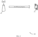
- FIG. 2 illustrates an example of a wireless communications system 200 that supports multicarrier on-off keying symbol randomizer in accordance with aspects of the present disclosure.
- wireless communications system 200 may implement aspects of wireless communications system 100.
- the wireless communications system 200 may include an AP 205 and a wireless station (STA) 210.
- the AP 205 may be an example of aspects of AP 105 described with reference to FIG. 1
- the STA 210 may be an example of aspects of STA 115 described with reference to FIG. 1 .
- the STA 210 may have an active communication mode, during which the STA 210 actively exchanges messages with other devices (e.g., the AP 205), and an idle communication mode, during which the STA 210 does not actively exchange messages with other devices.
- the STA 210 may listen to communications on the wireless communications medium in case another wireless device (e.g., the AP 205) has information to transmit to the STA 210, in which case the STA 210 may transition to active communication mode.
- the use of the main radio in idle mode may result in significant energy waste.
- the STA 210 may include a WUR which may consume less power than the main radio. The STA 210 may use to WUR during idle mode to decrease energy consumption in idle mode.
- the indication that the STA 210 should switch to active communication mode may be simple.
- the AP 205 may use on-off keying to indicate that the STA 210 should switch to active communication mode.
- the AP 205 may identify a sequence of on symbols and off symbols for transmission to the WUR of the STA 210.
- the on-off key sequence may be a multicarrier on-off sequence.
- the on-off key sequence may be defined in a technical specification and stored at the AP 205.
- the AP 205 may then assign a modulation symbol waveform from a set of possible modulation symbol waveforms to at least each on symbol in the sequence of on symbols and off symbols.
- the modulation symbol waveforms may be assigned to sequential on symbols in a random or pseudorandom order. In some examples, the modulation symbol waveforms may also be assigned to off symbols.
- the modulation symbol waveforms may be assigned to sequential on symbols by randomly or pseudorandomly selecting one of the possible modulation symbol waveforms for at least each on symbol.
- the set of possible modulation symbol waveforms may consist of a stored modulation symbol waveform with one of N possible phase rotations.
- the modulation symbol waveform for a symbol may be assigned by applying a random or pseudorandom phase rotation to the stored modulation symbol.
- the set of possible modulation symbol waveforms may consist of a stored modulation symbols waveform with one of N possible cyclic shift values.
- the modulation symbol waveform for a symbol is assigned by applying a random or pseudorandom cyclic shift to the stored modulation symbol.
- the set of possible modulation symbols may consist of a set of NxM modulation symbol waveforms, where N is the number of possible phase-shift keying values and M is the number of subcarriers in the multicarrier system.
- the modulation symbol waveform for a symbol may be assigned by generating a random or pseudorandom phase-shift keying value for each of the M subcarriers.
- the phase-shift keying value may be, for example, a binary phase-shift keying (BPSK) value or a quadrature phase-shift keying (QPSK) value
- the resulting modulation symbol waveform may be an orthogonal frequency division multiplexing (OFDM) modulation symbol waveform.
- BPSK binary phase-shift keying
- QPSK quadrature phase-shift keying
- the random or pseudorandom phase rotation, cyclic shift, or phase-shift keying value may be determined based at least in part on a random or pseudorandom number (e.g., a random or pseudorandom bit or string of bits).
- the random or pseudorandom number is determined based at least in part on a random number generator (e.g., a linear feedback shift register).
- the random number generator is initialized with a seed, which may be a fixed seed or a variable (e.g., random or pseudorandom) seed.
- the AP 205 transmits the seed (e.g., the variable seed) to the STA 210.
- the STA 210 may use the received seed to compensate at the receiver for the random or pseudorandom assignments (e.g., the random or pseudorandom phase rotation or cyclic shift).
- the random or pseudorandom number may be determined based at least in part on a stored random or pseudorandom number.
- a linear feedback shift register may generate a pseudorandom string of bits that repeats every 127 bits.
- the AP 205 may instead store a random or pseudorandom string of bits (which may have more than 127 bits).
- the AP 205 may transmit the sequence of on symbols and off symbols to the WUR of the STA 210 using multicarrier on-off keying (MC-OOK).
- the transmitted sequence may be based at least in part on the assigned modulation symbol waveforms.
- the AP 205 may transmit the corresponding assigned modulation symbol waveform during each on symbol.
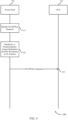
- FIG. 3 illustrates an example of a communication flow 300 in a wireless communications system that supports multicarrier on-off keying symbol randomizer in accordance with aspects of the present disclosure.
- communication flow 300 may implement aspects of wireless communications system 100.
- the communication flow 300 shows communications between an AP 305 and a STA 310.
- the AP 305 may be an example of aspects of AP 105 as described with reference to FIG. 1 .
- the STA 310 may be an example of aspects of STA 115 as described with reference to FIG. 1 .
- the AP 305 may identify an on-off key sequence at 315.
- the on-off key sequence may be a multicarrier on-off sequence.
- the on-off key sequence may include a plurality of on symbols and a plurality of off symbols.
- the on-off key sequence may be defined in a technical specification and stored at the AP 305 (e.g., in a memory).
- the AP 305 may randomly or pseudorandomly assign modulation symbol waveforms to on symbols of the on-off key sequence at 320. In some examples, the AP 305 may randomly or pseudorandomly assign modulation symbol waveforms to on symbols only. In some other examples, the AP 305 may randomly or pseudorandomly assign modulation symbol waveforms to the entire on-off key sequence, including the off symbols.
- the AP 305 may randomly or pseudorandomly assign a modulation symbol waveform to a symbol (e.g., an on symbol) based at least in part on a stored symbol.
- a random or pseudorandom change may be applied to the stored symbol to generate the modulation symbol waveform.
- the AP 305 may randomly or pseudorandomly assign a modulation symbol waveform to a symbol (e.g., an on symbol) by applying a random phase rotation to a stored symbol. In some examples, the AP 305 may randomly or pseudorandomly assign a modulation symbol waveform to a symbol (e.g., an on symbol) by applying a random cyclic shift to a stored symbol.
- the random phase rotation or cyclic shift may be determined based at least in part on a random or pseudorandom number (e.g., a bit or string of bits).
- the random or pseudorandom bit or string of bits may be generated by a random number generator such as a linear phase shift register.
- the linear phase shift register may be initialized based at least in part on a seed number.
- the seed number may be a fixed value (e.g., a value specified in a technical standard). In some other examples, the seed number may vary (e.g., randomly or pseudorandomly). In such examples, the AP 305 may transmit the seed to the STA 310.
- the STA 310 may use the received seed value in compensating for the random or pseudorandom phase rotation or cyclic shift.
- the random or pseudorandom bit or string of bits may be determined based at least in part on a random or pseudorandom number (string of bits).
- AP 305 may randomly or pseudorandomly assign a modulation symbol waveform to a symbol (e.g., an on symbol) without reference to a stored symbol.
- the AP 305 may generate a symbol by applying a random or pseudorandom phase shift keying value to each subcarrier in a multicarrier system.
- the generated symbol may be an orthogonal frequency division multiplexing (OFDM) symbol
- the phase shift keying value may be a binary phase-shift keying (BPSK) value or a quadrature phase-shift keying (QPSK) value.
- the random or pseudorandom phase-shift keying value may be determined based at least in part on a random or pseudorandom number (e.g., a bit or string of bits).
- the random or pseudorandom bit or string of bits may be generated by a random number generator such as a linear phase shift register.
- the linear phase shift register may be initialized based at least in part on a seed number.
- the seed number may be a fixed value (e.g., a value specified in a technical standard). In some other examples, the seed number may vary (e.g., randomly or pseudorandomly).
- the AP 305 may transmit the seed to the STA 310. If the STA 310 is a coherent receiver, the STA 310 may use the received seed value in compensating for the random or pseudorandom phase-shift keying values.
- the random or pseudorandom bit or string of bits may be determined based at least in part on a random or pseudorandom number (e.g., string of bits).
- the AP 305 may transmit the on-off key sequence 325 to the STA 310.
- the on-off key sequence 325 may be based at least in part on the modulation symbol waveforms randomly or pseudorandomly assigned to at least each on symbol.
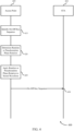
- FIG. 4 illustrates an example of a communication flow 400 in a wireless communications system that supports multicarrier on-off keying symbol randomizer in accordance with aspects of the present disclosure.
- communication flow 400 may implement aspects of wireless communications system 100.
- the communication flow 400 shows communications between an AP 405 and a STA 410.
- the AP 405 may be an example of aspects of AP 105 as described with reference to FIG. 1 .
- the STA 410 may be an example of aspects of STA 115 as described with reference to FIG. 1 .
- the AP 405 may identify an on-off key sequence at 415.
- the on-off key sequence may be a multicarrier on-off sequence.
- the on-off key sequence may include a plurality of on symbols and a plurality of off symbols.
- the on-off key sequence may be defined in a technical specification and stored at the AP 405 (e.g., in a memory).
- the AP 405 may determine a random or pseudorandom phase rotation for at least each on symbol at 420.
- the random or pseudorandom phase rotation may be determined based at least in part on a random number (e.g., bit or string of bits).
- the random or pseudorandom number may be generated by a random number generator such as random number generator 500 described with reference to FIG. 5 .
- the random or pseudorandom number may be determined based at least in part on a stored random or pseudorandom number, which may be stored at the AP 405 (e.g., in a memory).
- the AP 405 may determine the phase rotation based at least in part on a single random or pseudorandom bit (e.g., 0 or 1). For example, the AP 405 may determine a phase rotation of 0 degrees when the single bit is 0, and may determine a phase rotation of 180 degrees when the single bit is 1.
- a single random or pseudorandom bit e.g., 0 or 1
- the AP 405 may determine a phase rotation of 0 degrees when the single bit is 0, and may determine a phase rotation of 180 degrees when the single bit is 1.
- the AP 405 may determine the phase rotation based at least in part on a string of two random or pseudorandom bits (e.g., 00, 10, 01, 11). For example, the AP may determine a phase rotation of 1 degree when the string is 00, may determine a phase rotation of 90 degrees when the string is 10, may determine a phase rotation of 180 degrees when the string is 01, and may determine a phase rotation of 270 degrees when the string is 11.
- a string of two random or pseudorandom bits e.g., 00, 10, 01, 11
- the AP may determine a phase rotation of 1 degree when the string is 00, may determine a phase rotation of 90 degrees when the string is 10, may determine a phase rotation of 180 degrees when the string is 01, and may determine a phase rotation of 270 degrees when the string is 11.
- the AP 405 may determine the phase rotation based at least in part on a string of three or more random or pseudorandom bits.
- the phase rotations corresponding to a three-bit string are shown in Table 1. Other mappings and greater numbers of bits may also be used in connection with the disclosed subject matter.
- the AP 405 may apply the random or pseudorandom phase rotation to a stored waveform at 425.
- a single stored waveform may be used for each symbol.
- Applying the random or pseudorandom phase rotation may correspond to randomly or pseudorandomly assigning a modulation symbol waveform from a set of candidate modulation symbol waveforms. For example, when a two-bit string is used to select the phase rotation, and the phase rotation is applied to a single stored waveform, applying the phase rotation is equivalent to randomly or pseudorandomly selecting one of four possible modulation symbol waveforms to at least each on symbol.
- the AP 405 may transmit the on-off key sequence 430 to the STA 410.
- the on-off key sequence 430 may be based at least in part on the modulation symbol waveforms randomly or pseudorandomly assigned to at least each on symbol (e.g., based at least in part on the random or pseudorandom phase rotation applied to at least each on symbol).
- FIG. 5 illustrates an example of a random number generator 500 in a wireless communications system that supports multicarrier on-off keying symbol randomizer in accordance with aspects of the present disclosure.
- random number generator 500 may implement aspects of wireless communications system 100.
- the random number generator 500 may be a linear feedback shift register, which may be a linear feedback shift register as defined in the 802.11ba amendment to the Institute of Electrical and Electronics Engineers (IEEE) 802.11-2016 standard.
- the random number generator 500 may generate a pseudorandom sequence of bits that repeats every 127 bits.
- the random number generator 500 may be a component of a transmitting device, which may be an example of aspects of AP 105 described with reference to FIG. 1 .
- the random number generator 500 may include a register of seven bits. The seven bits may be divided into a first register 505 of three bits and a second register 510 of four bits. The pseudorandom sequence generated by the random number generator 500 may depend on the initial value of the bits in the first register 505 and the second register 510.
- the random number generator 500 may be initialized with a seed X 7 X 6 X 5 X 4 X 3 X 2 X 1 .
- the seed may be a fixed seed (e.g., may be specified in a technical standard).
- a variable seed e.g., a random or pseudorandom seed
- the variable seed may be transmitted to a receiving device, which may be an example of aspects of STA 115 as described with reference to FIG. 1 .
- the receiving device may be a coherent receiver.
- FIG. 6 illustrates an example of power spectral density measurements 600 at a high data rate in a wireless communications system that supports multicarrier on-off keying symbol randomizer in accordance with aspects of the present disclosure.
- the wireless communications system may implement aspects of wireless communications system 100.
- the power spectral density measurements 600 include a first graph 605 of power spectral density measurements at a low data rate and a second graph 610 of power spectral density measurements at a low data rate.
- the first graph 605 shows power spectral density measurements versus frequency when a same waveform is used for each on symbol in an on-off key sequence.
- the first graph 605 shows a number of power spectral lines in the power spectral density, which can result in significant power in a narrow bandwidth.
- the second graph 610 shows power spectral density versus frequency when a random or pseudorandom phase rotation is applied to each on symbol. The second graph 610 does not show power spectral lines, which indicates that the power in narrow bandwidths may be narrowed and problems associated with high narrowband power may be mitigated.
- Table 2 shows the calculated maximum power in any 3 kHz window as compared to total power, and the maximum power in any 3 kHz window if the total transmission power is 30 dBm.
- Table 2 shows the calculated maximum power in any 3 kHz window relative to the total power as -10.4 dB.
- the maximum power in any 3 kHz window is 19.6 dBm. This exceeds the limit of 8 dBm in any 3 kHz window set by the Federal Communications Commission (FCC).
- FCC Federal Communications Commission
- the use of waveforms with random or pseudorandom waveforms leads to a maximum power in any 3 kHz window relative to the total power as -27.0 dB.
- the maximum power in any 3 kHz window is 3.0 dBm, which satisfies the FCC requirement.
- FIG. 7 illustrates an example of power spectral density measurements 700 at a low data rate in a wireless communications system that supports multicarrier on-off keying symbol randomizer in accordance with aspects of the present disclosure.
- the wireless communications system may implement aspects of wireless communications system 100.
- the power spectral density measurements 700 include a first graph 705 of power spectral density measurements at a high data rate and a second graph 710 of power spectral density measurements at a high data rate.
- the first graph 705 shows power spectral density measurements versus frequency when a same waveform is used for each on symbol in an on-off key sequence.
- the first graph 705 shows a number of power spectral lines in the power spectral density, which can result in significant power in a narrow bandwidth.
- the second graph 710 shows power spectral density versus frequency when a random or pseudorandom phase rotation is applied to each on symbol.
- the second graph 710 does not show power spectral lines, which indicates that the power in narrow bandwidths may be narrowed and problems associated with high narrowband power may be mitigated.
- Table 3 shows the calculated maximum power in any 3 kHz window as compared to total power, and the maximum power in any 3 kHz window if the total transmission power is 30 dBm.
- Table 3 shows the calculated maximum power in any 3 kHz window relative to the total power as -12.5 dB.
- the maximum power in any 3 kHz window is 17.5 dBm. This exceeds the limit of 8 dBm in any 3 kHz window set by the FCC.
- the use of waveforms with random or pseudorandom waveforms leads to a maximum power in any 3 kHz window relative to the total power as -27.4 dB.
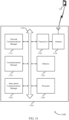
- FIG. 8 shows a block diagram 800 of a device 805 that supports multicarrier on-off keying symbol randomizer in accordance with aspects of the present disclosure.
- the device 805 may be an example of aspects of an AP as described herein.
- the device 805 may include a receiver 810, a communications manager 815, and a transmitter 820.
- the device 805 may also include a processor. Each of these components may be in communication with one another (e.g., via one or more buses).
- communications manager 815 may be implemented by a wireless modem.
- Communications manager 815 may communicate with transmitter 820 via a first interface.
- Communications manager 815 may output signals for transmission via the first interface.
- communications manager 815 may obtain signals received by receiver 810 from another wireless device via a second interface.
- the receiver 810 may receive information such as packets, user data, or control information associated with various information channels (e.g., control channels, data channels, and information related to multicarrier on-off keying symbol randomizer, etc.). Information may be passed on to other components of the device.
- the receiver 810 may be an example of aspects of the transceiver 1120 described with reference to FIG. 11 .
- the receiver 810 may utilize a single antenna or a set of antennas.
- the communications manager 815 may identify, by an AP, a sequence of on symbols and off symbols for transmission to a WUR of a wireless device, assign a modulation symbol waveform from a set of possible modulation symbol waveforms to at least each on symbol in the sequence, where the modulation symbol waveforms are assigned to sequential on symbols in a random or pseudorandom order, and transmit the sequence to the WUR of the wireless device using multi-carrier on-off keying (MC-OOK) based on the assigned modulation symbol waveforms.
- MC-OOK multi-carrier on-off keying
- the communications manager 815 may be an example of aspects of the communications manager 1110 described herein.
- the communications manager 815 may be implemented in hardware, code (e.g., software or firmware) executed by a processor, or any combination thereof. If implemented in code executed by a processor, the functions of the communications manager 815, or its sub-components may be executed by a general-purpose processor, a digital signal processor (DSP), an application-specific integrated circuit (ASIC), a field-programmable gate array (FPGA) or other programmable logic device, discrete gate or transistor logic, discrete hardware components, or any combination thereof designed to perform the functions described in the present disclosure.
- DSP digital signal processor
- ASIC application-specific integrated circuit
- FPGA field-programmable gate array
- the communications manager 815 may be physically located at various positions, including being distributed such that portions of functions are implemented at different physical locations by one or more physical components.
- the communications manager 815, or its sub-components may be a separate and distinct component in accordance with various aspects of the present disclosure.
- the communications manager 815, or its sub-components may be combined with one or more other hardware components, including but not limited to an input/output (I/O) component, a transceiver, a network server, another computing device, one or more other components described in the present disclosure, or a combination thereof in accordance with various aspects of the present disclosure.
- I/O input/output
- the transmitter 820 may transmit signals generated by other components of the device.
- the transmitter 820 may be collocated with a receiver 810 in a transceiver module.
- the transmitter 820 may be an example of aspects of the transceiver 1120 described with reference to FIG. 11 .
- the transmitter 820 may utilize a single antenna or a set of antennas.
- FIG. 9 shows a block diagram 900 of a device 905 that supports multicarrier on-off keying symbol randomizer in accordance with aspects of the present disclosure.
- the device 905 may be an example of aspects of a device 805 or an STA 115 as described herein.
- the device 905 may include a receiver 910, a communications manager 915, and a transmitter 935.
- the device 905 may also include a processor. Each of these components may be in communication with one another (e.g., via one or more buses).
- the receiver 910 may receive information such as packets, user data, or control information associated with various information channels (e.g., control channels, data channels, and information related to multicarrier on-off keying symbol randomizer, etc.). Information may be passed on to other components of the device.
- the receiver 910 may be an example of aspects of the transceiver 1120 described with reference to FIG. 11 .
- the receiver 910 may utilize a single antenna or a set of antennas.
- the communications manager 915 may be an example of aspects of the communications manager 815 as described herein.
- the communications manager 915 may include an on-off sequence identifier 920, a modulation symbol waveform assigner 925, and a sequence scheduler 930.
- the communications manager 915 may be an example of aspects of the communications manager 1110 described herein.
- the on-off sequence identifier 920 may identify, by an AP, a sequence of on symbols and off symbols for transmission to a WUR of a wireless device.
- the modulation symbol waveform assigner 925 may assign a modulation symbol waveform from a set of possible modulation symbol waveforms to at least each on symbol in the sequence, where the modulation symbol waveforms are assigned to sequential on symbols in a random or pseudorandom order.
- the sequence scheduler 930 may transmit the sequence to the WUR of the wireless device using multi-carrier on-off keying (MC-OOK) based on the assigned modulation symbol waveforms.
- MC-OOK multi-carrier on-off keying
- the transmitter 935 may transmit signals generated by other components of the device.
- the transmitter 935 may be collocated with a receiver 910 in a transceiver module.
- the transmitter 935 may be an example of aspects of the transceiver 1120 described with reference to FIG. 11 .
- the transmitter 935 may utilize a single antenna or a set of antennas.
- FIG. 10 shows a block diagram 1000 of a communications manager 1005 that supports multicarrier on-off keying symbol randomizer in accordance with aspects of the present disclosure.
- the communications manager 1005 may be an example of aspects of a communications manager 815, a communications manager 915, or a communications manager 1110 described herein.
- the communications manager 1005 may include an on-off sequence identifier 1010, a modulation symbol waveform assigner 1015, a sequence scheduler 1020, a phase rotation application unit 1025, a random number generator 1030, a seed transmission unit 1035, a cyclic shift application unit 1040, and a phase shift key (PSK) application unit 1045.
- Each of these modules may communicate, directly or indirectly, with one another (e.g., via one or more buses).
- the on-off sequence identifier 1010 may identify, by an AP, a sequence of on symbols and off symbols for transmission to a WUR of a wireless device.
- the modulation symbol waveform assigner 1015 may assign a modulation symbol waveform from a set of possible modulation symbol waveforms to at least each on symbol in the sequence, where the modulation symbol waveforms are assigned to sequential on symbols in a random or pseudorandom order.
- the modulation symbol waveform assigner 1015 may assign a modulation symbol waveform from a set of possible modulation symbol waveforms to each off symbol in the sequence, where the modulation symbol waveforms are assigned to sequential symbols in the sequence in a random or pseudorandom order.
- the sequence scheduler 1020 may transmit the sequence to the WUR of the wireless device using multi-carrier on-off keying (MC-OOK) based on the assigned modulation symbol waveforms.
- MC-OOK multi-carrier on-off keying
- the phase rotation application unit 1025 may apply a random or pseudorandom phase rotation to a stored modulation symbol waveform. In some examples, the phase rotation application unit 1025 may determine the random or pseudorandom phase rotation based on a random number generator. In some examples, the phase rotation application unit 1025 may determine the random or pseudorandom phase rotation based on a stored random or pseudorandom number sequence.
- the random number generator 1030 may initialize the linear feedback shift register with a fixed seed. In some examples, the random number generator 1030 may initialize the linear feedback shift register with a random or pseudorandom seed.
- the random or pseudorandom number generator includes a linear feedback shift register.
- the seed transmission unit 1035 may transmit the random or pseudorandom seed to the wireless device.
- the cyclic shift application unit 1040 may apply a random or pseudorandom cyclic shift to a stored modulation symbol waveform.
- the PSK application unit 1045 may apply a random or pseudorandom phase-shift keying value to each of a set of subcarriers of a multicarrier system to generate the modulation symbol waveform.
- the modulation symbol waveform includes an orthogonal frequency division multiplexing symbol waveform.
- the random or pseudorandom phase-shift keying value includes one of a binary phase-shift keying value and a quadrature phase-shift keying value.
- FIG. 11 shows a diagram of a system 1100 including a device 1105 that supports multicarrier on-off keying symbol randomizer in accordance with aspects of the present disclosure.
- the device 1105 may be an example of or include the components of device 805, device 905, or an AP as described herein.
- the device 1105 may include components for bidirectional voice and data communications including components for transmitting and receiving communications, including a communications manager 1110, a network communications manager 1115, a transceiver 1120, an antenna 1125, memory 1130, a processor 1140, and an inter-station communications manager 1145. These components may be in electronic communication via one or more buses (e.g., bus 1150).
- buses e.g., bus 1150
- the communications manager 1110 may identify, by an AP, a sequence of on symbols and off symbols for transmission to a WUR of a wireless device, assign a modulation symbol waveform from a set of possible modulation symbol waveforms to at least each on symbol in the sequence, where the modulation symbol waveforms are assigned to sequential on symbols in a random or pseudorandom order, and transmit the sequence to the WUR of the wireless device using multi-carrier on-off keying (MC-OOK) based on the assigned modulation symbol waveforms.
- MC-OOK multi-carrier on-off keying
- the network communications manager 1115 may manage communications with the core network (e.g., via one or more wired backhaul links). For example, the network communications manager 1115 may manage the transfer of data communications for client devices, such as one or more STAs 115.
- the transceiver 1120 may communicate bi-directionally, via one or more antennas, wired, or wireless links as described above.
- the transceiver 1120 may represent a wireless transceiver and may communicate bi-directionally with another wireless transceiver.
- the transceiver 1120 may also include a modem to modulate the packets and provide the modulated packets to the antennas for transmission, and to demodulate packets received from the antennas.
- the wireless device may include a single antenna 1125. However, in some cases the device may have more than one antenna 1125, which may be capable of concurrently transmitting or receiving multiple wireless transmissions.
- the memory 1130 may include random access memory (RAM) and read only memory (ROM).
- RAM random access memory
- ROM read only memory
- the memory 1130 may store computer-readable, computer-executable code 11 35 including instructions that, when executed, cause the processor to perform various functions described herein.
- the memory 1130 may contain, among other things, a basic input output system (BIOS) which may control basic hardware or software operation such as the interaction with peripheral components or devices.
- BIOS basic input output system
- the processor 1140 may include an intelligent hardware device, (e.g., a general-purpose processor, a DSP, a CPU, a microcontroller, an ASIC, an FPGA, a programmable logic device, a discrete gate or transistor logic component, a discrete hardware component, or any combination thereof).
- the processor 1140 may be configured to operate a memory array using a memory controller.
- a memory controller may be integrated into processor 1140.
- the processor 1140 may be configured to execute computer-readable instructions stored in a memory to perform various functions (e.g., functions or tasks supporting multicarrier on-off keying symbol randomizer).
- the inter-station communications manager 1145 may manage communications with other APs 105, and may include a controller or scheduler for controlling communications with STAs 115 in cooperation with other APs 105. For example, the inter-station communications manager 1145 may coordinate scheduling for transmissions to STAs 115 for various interference mitigation techniques such as beamforming or joint transmission. In some examples, the inter-station communications manager 1145 may provide an X2 interface within a LTE/LTE-A wireless communication network technology to provide communication between APs 105.
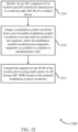
- FIG. 12 shows a flowchart illustrating a method 1200 that supports multicarrier on-off keying symbol randomizer in accordance with aspects of the present disclosure.
- the operations of method 1200 may be implemented by an AP or its components as described herein.
- the operations of method 1200 may be performed by a communications manager as described with reference to FIGs. 8 through 11 .
- an AP may execute a set of instructions to control the functional elements of the AP to perform the functions described below. Additionally, or alternatively, an AP may perform aspects of the functions described below using special-purpose hardware.
- the AP may identify, by an AP, a sequence of on symbols and off symbols for transmission to a WUR of a wireless device.
- the operations of 1205 may be performed according to the methods described herein. In some examples, aspects of the operations of 1205 may be performed by an on-off sequence identifier as described with reference to FIGs. 8 through 11 .
- the AP may assign a modulation symbol waveform from a set of possible modulation symbol waveforms to at least each on symbol in the sequence, where the modulation symbol waveforms are assigned to sequential on symbols in a random or pseudorandom order.
- the operations of 1210 may be performed according to the methods described herein. In some examples, aspects of the operations of 1210 may be performed by a modulation symbol waveform assigner as described with reference to FIGs. 8 through 11 .
- the AP may transmit the sequence to the WUR of the wireless device using multi-carrier on-off keying (MC-OOK) based on the assigned modulation symbol waveforms.
- MC-OOK multi-carrier on-off keying
- the operations of 1215 may be performed according to the methods described herein. In some examples, aspects of the operations of 1215 may be performed by a sequence scheduler as described with reference to FIGs. 8 through 11 .
- FIG. 13 shows a flowchart illustrating a method 1300 that supports multicarrier on-off keying symbol randomizer in accordance with aspects of the present disclosure.
- the operations of method 1300 may be implemented by an AP or its components as described herein.
- the operations of method 1300 may be performed by a communications manager as described with reference to FIGs. 8 through 11 .
- an AP may execute a set of instructions to control the functional elements of the AP to perform the functions described below. Additionally, or alternatively, an AP may perform aspects of the functions described below using special-purpose hardware.
- the AP may identify, by an AP, a sequence of on symbols and off symbols for transmission to a WUR of a wireless device.
- the operations of 1305 may be performed according to the methods described herein. In some examples, aspects of the operations of 1305 may be performed by an on-off sequence identifier as described with reference to FIGs. 8 through 11 .
- the AP may determine the random or pseudorandom phase rotation based on a random number generator.
- the operations of 1310 may be performed according to the methods described herein. In some examples, aspects of the operations of 1310 may be performed by a phase rotation application unit as described with reference to FIGs. 8 through 11 .
- the AP may apply a random or pseudorandom phase rotation to a stored modulation symbol waveform.
- the operations of 1315 may be performed according to the methods described herein. In some examples, aspects of the operations of 1315 may be performed by a phase rotation application unit as described with reference to FIGs. 8 through 11 .
- the AP may transmit the sequence to the WUR of the wireless device using multi-carrier on-off keying (MC-OOK) based on the assigned modulation symbol waveforms.
- MC-OOK multi-carrier on-off keying
- the operations of 1320 may be performed according to the methods described herein. In some examples, aspects of the operations of 1320 may be performed by a sequence scheduler as described with reference to FIGs. 8 through 11 .
- FIG. 14 shows a flowchart illustrating a method 1400 that supports multicarrier on-off keying symbol randomizer in accordance with aspects of the present disclosure.
- the operations of method 1400 may be implemented by an AP or its components as described herein.
- the operations of method 1400 may be performed by a communications manager as described with reference to FIGs. 8 through 11 .
- an AP may execute a set of instructions to control the functional elements of the AP to perform the functions described below. Additionally, or alternatively, an AP may perform aspects of the functions described below using special-purpose hardware.
- the AP may identify, by an AP, a sequence of on symbols and off symbols for transmission to a WUR of a wireless device.
- the operations of 1405 may be performed according to the methods described herein. In some examples, aspects of the operations of 1405 may be performed by an on-off sequence identifier as described with reference to FIGs. 8 through 11 .
- the AP may assign a modulation symbol waveform from a set of possible modulation symbol waveforms to at least each on symbol in the sequence, where the modulation symbol waveforms are assigned to sequential on symbols in a random or pseudorandom order.
- the operations of 1410 may be performed according to the methods described herein. In some examples, aspects of the operations of 1410 may be performed by a modulation symbol waveform assigner as described with reference to FIGs. 8 through 11 .
- the AP may assign a modulation symbol waveform from a set of possible modulation symbol waveforms to each off symbol in the sequence, where the modulation symbol waveforms are assigned to sequential symbols in the sequence in a random or pseudorandom order.
- the operations of 1415 may be performed according to the methods described herein. In some examples, aspects of the operations of 1415 may be performed by a modulation symbol waveform assigner as described with reference to FIGs. 8 through 11 .
- the AP may transmit the sequence to the WUR of the wireless device using multi-carrier on-off keying (MC-OOK) based on the assigned modulation symbol waveforms.
- MC-OOK multi-carrier on-off keying
- the operations of 1420 may be performed according to the methods described herein. In some examples, aspects of the operations of 1420 may be performed by a sequence scheduler as described with reference to FIGs. 8 through 11 .
- CDMA code division multiple access
- TDMA time division multiple access
- FDMA frequency division multiple access
- OFDMA orthogonal frequency division multiple access
- SC-FDMA single carrier frequency division multiple access
- CDMA2000 covers IS-2000, IS-95, and IS-856 standards.
- IS-2000 Releases may be commonly referred to as CDMA2000 1X, 1X, etc.
- IS-856 (TIA-856) is commonly referred to as CDMA2000 1xEV-DO, High Rate Packet Data (HRPD), etc.
- UTRA includes Wideband CDMA (WCDMA) and other variants of CDMA.
- WCDMA Wideband CDMA
- a time division multiple access (TDMA) system may implement a radio technology such as Global System for Mobile Communications (GSM).
- GSM Global System for Mobile Communications
- An orthogonal frequency division multiple access (OFDMA) system may implement a radio technology such as Ultra Mobile Broadband (UMB), Evolved UTRA (E-UTRA), IEEE 802.11 (Wi-Fi), IEEE 802.16 (WiMAX), IEEE 802.20, Flash-OFDM, etc.
- UMB Ultra Mobile Broadband
- E-UTRA Evolved UTRA
- Wi-Fi Wi-Fi
- WiMAX IEEE 802.16
- IEEE 802.20 Flash-OFDM
- the wireless communications system or systems described herein may support synchronous or asynchronous operation.
- the stations may have similar frame timing, and transmissions from different stations may be approximately aligned in time.
- the stations may have different frame timing, and transmissions from different stations may not be aligned in time.
- the techniques described herein may be used for either synchronous or asynchronous operations.
- Information and signals described herein may be represented using any of a variety of different technologies and techniques.
- data, instructions, commands, information, signals, bits, symbols, and chips that may be referenced throughout the above description may be represented by voltages, currents, electromagnetic waves, magnetic fields or particles, optical fields or particles, or any combination thereof.
- a general-purpose processor may be a microprocessor, but in the alternative, the processor may be any conventional processor, controller, microcontroller, or state machine.
- a processor may also be implemented as a combination of computing devices (e.g., a combination of a DSP and a microprocessor, multiple microprocessors, one or more microprocessors in conjunction with a DSP core, or any other such configuration).
- the functions described herein may be implemented in hardware, software executed by a processor, firmware, or any combination thereof. If implemented in software executed by a processor, the functions may be stored on or transmitted over as one or more instructions or code on a computer-readable medium. Other examples and implementations are within the scope of the disclosure and appended claims. For example, due to the nature of software, functions described above may be implemented using software executed by a processor, hardware, firmware, hardwiring, or combinations of any of these. Features implementing functions may also be physically located at various positions, including being distributed such that portions of functions are implemented at different physical locations.
- Computer-readable media includes both non-transitory computer storage media and communication media including any medium that facilitates transfer of a computer program from one place to another.
- a non-transitory storage medium may be any available medium that can be accessed by a general purpose or special purpose computer.
- non-transitory computer-readable media can comprise RAM, ROM, electrically erasable programmable read only memory (EEPROM), compact disk (CD) ROM or other optical disk storage, magnetic disk storage or other magnetic storage devices, or any other non-transitory medium that can be used to carry or store desired program code means in the form of instructions or data structures and that can be accessed by a general-purpose or special-purpose computer, or a general-purpose or special-purpose processor.
- RAM random access memory
- ROM read only memory
- EEPROM electrically erasable programmable read only memory
- CD compact disk
- magnetic disk storage or other magnetic storage devices or any other non-transitory medium that can be used to carry or store desired program code means in the form of instructions or data structures
- any connection is properly termed a computer-readable medium.
- the software is transmitted from a website, server, or other remote source using a coaxial cable, fiber optic cable, twisted pair, digital subscriber line (DSL), or wireless technologies such as infrared, radio, and microwave
- the coaxial cable, fiber optic cable, twisted pair, digital subscriber line (DSL), or wireless technologies such as infrared, radio, and microwave are included in the definition of medium.
- Disk and disc include CD, laser disc, optical disc, digital versatile disc (DVD), floppy disk and Blu-ray disc where disks usually reproduce data magnetically, while discs reproduce data optically with lasers. Combinations of the above are also included within the scope of computer-readable media.
Landscapes
- Engineering & Computer Science (AREA)
- Signal Processing (AREA)
- Computer Networks & Wireless Communication (AREA)
- Mobile Radio Communication Systems (AREA)
- Channel Selection Circuits, Automatic Tuning Circuits (AREA)
- Circuits Of Receivers In General (AREA)
Claims (7)
- Procédé de communication sans fil réalisé par un premier dispositif sans fil, comprenant les étapes consistant à :identifier, par le premier dispositif sans fil, une séquence de symboles ON et de symboles OFF en vue d'une transmission à une radio de réveil, WUR, d'un second dispositif sans fil (1205) ;déterminer un décalage cyclique aléatoire ou pseudo-aléatoire sur la base, au moins en partie, d'un générateur de nombres aléatoires, le générateur de nombres aléatoires étant initialisé avec une amorce aléatoire ou pseudo-aléatoire ;attribuer, à au moins chaque symbole ON de la séquence, une forme d'onde de symbole de modulation à partir d'un ensemble de formes d'ondes de symbole de modulation possibles, les formes d'ondes de symbole de modulation étant attribuées à des symboles ON séquentiels dans un ordre aléatoire ou pseudo-aléatoire (1210), et l'attribution de la forme d'onde de symbole de modulation comprenant les étapes consistant à sélectionner un décalage cyclique aléatoire ou pseudo-aléatoire pour chaque symbole et à appliquer le décalage cyclique aléatoire ou pseudo-aléatoire à une forme d'onde de symbole de modulation stockée afin de générer la forme d'onde de symbole de modulation pour chaque symbole ;transmettre la séquence à la WUR du second dispositif sans fil au moyen d'une modulation multiporteuse par tout ou rien, MC-OOK, sur la base, au moins en partie, des formes d'onde de symbole de modulation attribuées ; ettransmettre l'amorce aléatoire ou pseudo-aléatoire au second dispositif sans fil.
- Procédé selon la revendication 1, dans lequel le générateur de nombres aléatoires ou pseudo-aléatoires comprend un registre à décalage à rebouclage linéaire.
- Procédé selon la revendication 1, comprenant en outre l'étape consistant à :
attribuer, à chaque symbole OFF de la séquence, une forme d'onde de symbole de modulation à partir d'un ensemble de formes d'ondes de symbole de modulation possibles, les formes d'ondes de symbole de modulation étant attribuées à des symboles séquentiels de la séquence dans un ordre aléatoire ou pseudo-aléatoire. - Premier dispositif sans fil, comprenant :
une interface ; et
un modem sans fil, configuré pour :identifier une séquence de symboles ON et de symboles OFF en vue d'une transmission à une radio de réveil, WUR, d'un second dispositif sans fil ;déterminer un décalage cyclique aléatoire ou pseudo-aléatoire sur la base, au moins en partie, d'un générateur de nombres aléatoires, le générateur de nombres aléatoires étant initialisé avec une amorce aléatoire ou pseudo-aléatoire ;attribuer, à au moins chaque symbole ON de la séquence, une forme d'onde de symbole de modulation à partir d'un ensemble de formes d'ondes de symbole de modulation possibles, les formes d'ondes de symbole de modulation étant attribuées à des symboles ON séquentiels dans un ordre aléatoire ou pseudo-aléatoire, et l'attribution de la forme d'onde de symbole de modulation comprenant la sélection d'un décalage cyclique aléatoire ou pseudo-aléatoire pour chaque symbole et l'application du décalage cyclique aléatoire ou pseudo-aléatoire à une forme d'onde de symbole de modulation stockée afin de générer la forme d'onde de symbole de modulation pour chaque symbole ;délivrer en sortie la séquence sur l'interface en vue d'une transmission à la WUR du second dispositif sans fil au moyen d'une modulation multiporteuse par tout ou rien, MC-OOK, sur la base, au moins en partie, des formes d'onde de symbole de modulation attribuées ; ettransmettre l'amorce aléatoire ou pseudo-aléatoire au second dispositif sans fil. - Premier dispositif sans fil selon la revendication 4, dans lequel le modem sans fil est en outre configuré pour attribuer, à chaque symbole OFF de la séquence, une forme d'onde de symbole de modulation à partir d'un ensemble de formes d'ondes de symbole de modulation possibles, les formes d'ondes de symbole de modulation étant attribuées à des symboles séquentiels de la séquence dans un ordre aléatoire ou pseudo-aléatoire.
- Premier dispositif sans fil selon la revendication 4, dans lequel le générateur de nombres aléatoires ou pseudo-aléatoires comprend un registre à décalage à rebouclage linéaire.
- Support non temporaire et lisible par ordinateur, stockant un code pour une communication sans fil, le code comprenant des instructions qui, lorsqu'elles sont exécutées par un processeur, amènent le processeur à :identifier, par un premier dispositif sans fil, une séquence de symboles ON et de symboles OFF en vue d'une transmission à une radio de réveil, WUR, d'un second dispositif sans fil ;déterminer un décalage cyclique aléatoire ou pseudo-aléatoire sur la base, au moins en partie, d'un générateur de nombres aléatoires, le générateur de nombres aléatoires étant initialisé avec une amorce aléatoire ou pseudo-aléatoire ;attribuer, à au moins chaque symbole ON de la séquence, une forme d'onde de symbole de modulation à partir d'un ensemble de formes d'ondes de symbole de modulation possibles, les formes d'ondes de symbole de modulation étant attribuées à des symboles ON séquentiels dans un ordre aléatoire ou pseudo-aléatoire, et l'attribution de la forme d'onde de symbole de modulation comprenant la sélection d'un décalage cyclique aléatoire ou pseudo-aléatoire pour chaque symbole et l'application du décalage cyclique aléatoire ou pseudo-aléatoire à une forme d'onde de symbole de modulation stockée afin de générer la forme d'onde de symbole de modulation pour chaque symbole ; ettransmettre la séquence à la WUR du second dispositif sans fil au moyen d'une modulation multiporteuse par tout ou rien, MC-OOK, sur la base, au moins en partie, des formes d'onde de symbole de modulation attribuées, ettransmettre l'amorce aléatoire ou pseudo-aléatoire au second dispositif sans fil.
Applications Claiming Priority (3)
| Application Number | Priority Date | Filing Date | Title |
|---|---|---|---|
| US201862665293P | 2018-05-01 | 2018-05-01 | |
| US16/397,140 US11160020B2 (en) | 2018-05-01 | 2019-04-29 | Multicarrier on-off keying symbol randomizer |
| PCT/US2019/029922 WO2019213085A1 (fr) | 2018-05-01 | 2019-04-30 | Randomiseur de symboles de modulation en tout-ou-rien multiporteuse |
Publications (3)
| Publication Number | Publication Date |
|---|---|
| EP3788751A1 EP3788751A1 (fr) | 2021-03-10 |
| EP3788751C0 EP3788751C0 (fr) | 2025-05-21 |
| EP3788751B1 true EP3788751B1 (fr) | 2025-05-21 |
Family
ID=68385650
Family Applications (1)
| Application Number | Title | Priority Date | Filing Date |
|---|---|---|---|
| EP19725801.5A Active EP3788751B1 (fr) | 2018-05-01 | 2019-04-30 | Randomiseur de symboles de modulation en tout-ou-rien multiporteuse |
Country Status (5)
| Country | Link |
|---|---|
| US (1) | US11160020B2 (fr) |
| EP (1) | EP3788751B1 (fr) |
| CN (1) | CN112042160B (fr) |
| TW (1) | TWI771583B (fr) |
| WO (1) | WO2019213085A1 (fr) |
Families Citing this family (10)
| Publication number | Priority date | Publication date | Assignee | Title |
|---|---|---|---|---|
| US10932193B2 (en) * | 2018-05-30 | 2021-02-23 | Intel Corporation | Wake up receiver transmit waveform |
| CN112292892A (zh) * | 2018-06-25 | 2021-01-29 | 瑞典爱立信有限公司 | 传送和接收数据符号 |
| EP3830686B1 (fr) * | 2018-07-31 | 2025-09-03 | Telefonaktiebolaget LM Ericsson (publ) | Procédé, émetteur et point d'accès appropriés pour une mise en oeuvre à faible complexité |
| KR102463555B1 (ko) * | 2018-07-31 | 2022-11-07 | 텔레호낙티에볼라게트 엘엠 에릭슨(피유비엘) | 멀티캐리어 온-오프 키잉 신호의 프로비전을 위한 방법, 송신기, 구조체, 트랜시버 및 액세스 포인트 |
| EP3847787B1 (fr) * | 2018-09-07 | 2022-12-21 | Telefonaktiebolaget Lm Ericsson (Publ) | Transmission de signaux |
| US11778560B2 (en) * | 2019-07-10 | 2023-10-03 | Telefonaktiebolaget Lm Ericsson (Publ) | Avoiding false detection associated with wake-up signal |
| US11418422B1 (en) * | 2021-02-08 | 2022-08-16 | Mellanox Technologies, Ltd. | Received-signal rate detection |
| WO2022198424A1 (fr) * | 2021-03-23 | 2022-09-29 | 海能达通信股份有限公司 | Procédé et système de communication, dispositif associé et support de stockage |
| EP4443981A4 (fr) * | 2021-11-30 | 2025-10-01 | Guangdong Oppo Mobile Telecommunications Corp Ltd | Procédé et appareil pour surveiller un canal de commande, dispositif et support de stockage |
| CN119363536B (zh) * | 2023-07-24 | 2026-04-14 | 中国电信股份有限公司技术创新中心 | 信号生成方法、装置、通信系统 |
Citations (1)
| Publication number | Priority date | Publication date | Assignee | Title |
|---|---|---|---|---|
| WO2019173023A1 (fr) * | 2018-03-05 | 2019-09-12 | Qualcomm Incorporated | Diversité de transmission d'un module radio de réveil |
Family Cites Families (22)
| Publication number | Priority date | Publication date | Assignee | Title |
|---|---|---|---|---|
| DE102004006446B4 (de) * | 2004-02-03 | 2010-06-17 | Atmel Automotive Gmbh | Verfahren und Schaltungsanordnung zur drahtlosen Datenübertragung |
| US20070047665A1 (en) * | 2005-08-25 | 2007-03-01 | Friend Daniel H | Methods and systems for communicating signals through multi-carrier systems |
| US9065714B2 (en) * | 2007-01-10 | 2015-06-23 | Qualcomm Incorporated | Transmission of information using cyclically shifted sequences |
| KR100987266B1 (ko) * | 2007-02-14 | 2010-10-12 | 삼성전자주식회사 | 단일 반송파 주파수 분할 다중접속 시스템에서 제어정보 송수신 방법 및 장치 |
| WO2012015218A2 (fr) * | 2010-07-26 | 2012-02-02 | 엘지전자 주식회사 | Procédé et dispositif pour transmettre un signal de référence de sondage et des informations étendues de commande de liaison montante dans un système de communication sans fil |
| US9106389B2 (en) * | 2010-12-23 | 2015-08-11 | Qualcomm Incorporated | Interference randomization for uplink signaling |
| US8654819B2 (en) * | 2011-06-22 | 2014-02-18 | Harris Corporation | Systems and methods for pulse rotation modulation encoding and decoding |
| WO2014163429A1 (fr) * | 2013-04-05 | 2014-10-09 | 엘지전자 주식회사 | Procédé de transmission d'informations de commande en liaison montante dans un système d'accès sans fil et appareil associé |
| US9178735B1 (en) | 2014-07-23 | 2015-11-03 | Lattice Semiconductor Corporation | Phase-modulated on-off keying for millimeter wave spectrum control |
| US10491261B1 (en) * | 2014-11-06 | 2019-11-26 | Abdullah A. Al-Eidan | Multi carrier frequency modulation spread spectrum communication system |
| US9621197B2 (en) * | 2015-03-10 | 2017-04-11 | Samsung Electronics Co., Ltd. | Bi-phased on-off keying (OOK) transmitter and communication method |
| JP6246426B2 (ja) * | 2015-06-04 | 2017-12-13 | 三菱電機株式会社 | 送信装置および受信装置 |
| WO2017057943A1 (fr) * | 2015-09-30 | 2017-04-06 | 엘지전자(주) | Procédé pour émettre un signal de liaison montante dans un système de communication sans fil et dispositif associé |
| US10171277B2 (en) * | 2016-07-14 | 2019-01-01 | Huawei Technologies Co., Ltd. | Frame format and design of wake-up frame for a wake-up receiver |
| US10129064B1 (en) * | 2016-08-02 | 2018-11-13 | Newracom, Inc. | Wireless device low power wake up |
| US20180115953A1 (en) * | 2016-10-21 | 2018-04-26 | Qualcomm Incorporated | Phase modulated wakeup message for a wakeup radio |
| WO2018074740A1 (fr) * | 2016-10-23 | 2018-04-26 | 엘지전자 주식회사 | Procédé d'émission et de réception de signal de réveil dans un système de réseau local (lan) sans fil, et appareil associé |
| US10644820B2 (en) * | 2017-02-06 | 2020-05-05 | Huawei Technologies Co., Ltd. | Waveform-coding for multicarrier wake up radio frame |
| EP3619901A1 (fr) * | 2017-05-05 | 2020-03-11 | Interdigital Patent Holdings, Inc. | Coexistence de signaux de multiplexage par répartition orthogonale de la fréquence (mrof) et de modulation par tout ou rien (ook) dans un réseau local sans fil (wlan) |
| US11212026B2 (en) * | 2017-07-07 | 2021-12-28 | Panasonic Intellectual Property Corporation Of America | Radio transmission device and transmission method |
| CN111512677B (zh) * | 2018-01-11 | 2023-10-03 | 松下电器(美国)知识产权公司 | 用于低功率多用户传输的通信装置和通信方法 |
| US10779236B2 (en) * | 2018-04-11 | 2020-09-15 | Intel Corporation | Methods to encode a binary phase shift keying (BPSK) mark for a wake-up radio (WUR) packet |
-
2019
- 2019-04-29 US US16/397,140 patent/US11160020B2/en active Active
- 2019-04-30 CN CN201980029156.3A patent/CN112042160B/zh active Active
- 2019-04-30 TW TW108115028A patent/TWI771583B/zh active
- 2019-04-30 WO PCT/US2019/029922 patent/WO2019213085A1/fr not_active Ceased
- 2019-04-30 EP EP19725801.5A patent/EP3788751B1/fr active Active
Patent Citations (1)
| Publication number | Priority date | Publication date | Assignee | Title |
|---|---|---|---|---|
| WO2019173023A1 (fr) * | 2018-03-05 | 2019-09-12 | Qualcomm Incorporated | Diversité de transmission d'un module radio de réveil |
Non-Patent Citations (1)
| Title |
|---|
| NOKIA SIEMENS NETWORKS ET AL: "Symbol based cyclic shift hopping", 3GPP DRAFT; R1-073643, 3RD GENERATION PARTNERSHIP PROJECT (3GPP), MOBILE COMPETENCE CENTRE ; 650, ROUTE DES LUCIOLES ; F-06921 SOPHIA-ANTIPOLIS CEDEX ; FRANCE, vol. RAN WG1, no. Athens, Greece; 20070815, 15 August 2007 (2007-08-15), XP050107239 * |
Also Published As
| Publication number | Publication date |
|---|---|
| CN112042160A (zh) | 2020-12-04 |
| TWI771583B (zh) | 2022-07-21 |
| US11160020B2 (en) | 2021-10-26 |
| TW201946483A (zh) | 2019-12-01 |
| EP3788751C0 (fr) | 2025-05-21 |
| US20190342828A1 (en) | 2019-11-07 |
| EP3788751A1 (fr) | 2021-03-10 |
| CN112042160B (zh) | 2023-08-15 |
| WO2019213085A1 (fr) | 2019-11-07 |
Similar Documents
| Publication | Publication Date | Title |
|---|---|---|
| US11160020B2 (en) | Multicarrier on-off keying symbol randomizer | |
| US20220393843A1 (en) | Dual band channel bonding and puncturing | |
| US12185113B2 (en) | Wireless communication method and wireless communication terminal for spatial reuse of overlapped basic service set | |
| US20260067930A1 (en) | Wireless communication method and wireless communication terminal in high density environment including overlapped basic service sets | |
| JP6563584B2 (ja) | 高効率ワイヤレスローカルエリアネットワークプリアンブルにおけるリソース割り振りシグナリング | |
| US20180152333A1 (en) | Multicarrier on-off keying waveform coding | |
| US20180103487A1 (en) | Dynamic selection of control response frame parameters | |
| US20190273647A1 (en) | Wakeup radio transmit diversity | |
| WO2020041661A1 (fr) | Améliorations de balayage pour canaux wifi de prochaine génération | |
| US10764946B2 (en) | Autonomous mesh topology | |
| KR20210122812A (ko) | 비면허 nr에서 유효 rach 기회 결정을 위한 방법 및 장치 | |
| US10091682B2 (en) | Uplink airtime fairness through basic service set steering | |
| US20190021007A1 (en) | Station-aided spatial reuse group detection | |
| US20180220430A1 (en) | A first node and a method therein | |
| US20250203383A1 (en) | Transmissions on mixed dynamic frequency selection channels during channel availability check | |
| WO2011105852A2 (fr) | Procédé et appareil d'attribution de canal de transmission dans un système de réseau local sans fil | |
| WO2024060241A1 (fr) | Procédé et appareil de détermination de type d'attribution de ressources de domaine fréquentiel, et dispositif et support d'enrgistrement | |
| US20190380094A1 (en) | Token wakeup signaling | |
| CA3028385C (fr) | Amelioration de l'equite de temps d'utilisation de liaison montante par orientation de l'ensemble de services de base |
Legal Events
| Date | Code | Title | Description |
|---|---|---|---|
| STAA | Information on the status of an ep patent application or granted ep patent |
Free format text: STATUS: UNKNOWN |
|
| STAA | Information on the status of an ep patent application or granted ep patent |
Free format text: STATUS: THE INTERNATIONAL PUBLICATION HAS BEEN MADE |
|
| PUAI | Public reference made under article 153(3) epc to a published international application that has entered the european phase |
Free format text: ORIGINAL CODE: 0009012 |
|
| STAA | Information on the status of an ep patent application or granted ep patent |
Free format text: STATUS: REQUEST FOR EXAMINATION WAS MADE |
|
| 17P | Request for examination filed |
Effective date: 20201008 |
|
| AK | Designated contracting states |
Kind code of ref document: A1 Designated state(s): AL AT BE BG CH CY CZ DE DK EE ES FI FR GB GR HR HU IE IS IT LI LT LU LV MC MK MT NL NO PL PT RO RS SE SI SK SM TR |
|
| AX | Request for extension of the european patent |
Extension state: BA ME |
|
| DAV | Request for validation of the european patent (deleted) | ||
| DAX | Request for extension of the european patent (deleted) | ||
| STAA | Information on the status of an ep patent application or granted ep patent |
Free format text: STATUS: EXAMINATION IS IN PROGRESS |
|
| 17Q | First examination report despatched |
Effective date: 20220225 |
|
| REG | Reference to a national code |
Ref country code: DE Ref legal event code: R079 Free format text: PREVIOUS MAIN CLASS: H04L0027040000 Ipc: H04W0052020000 Ref country code: DE Ref legal event code: R079 Ref document number: 602019070219 Country of ref document: DE Free format text: PREVIOUS MAIN CLASS: H04L0027040000 Ipc: H04W0052020000 |
|
| GRAP | Despatch of communication of intention to grant a patent |
Free format text: ORIGINAL CODE: EPIDOSNIGR1 |
|
| STAA | Information on the status of an ep patent application or granted ep patent |
Free format text: STATUS: GRANT OF PATENT IS INTENDED |
|
| RIC1 | Information provided on ipc code assigned before grant |
Ipc: H04L 27/20 20060101ALI20241130BHEP Ipc: H04L 5/00 20060101ALI20241130BHEP Ipc: H04L 27/04 20060101ALI20241130BHEP Ipc: H04W 52/02 20090101AFI20241130BHEP |
|
| INTG | Intention to grant announced |
Effective date: 20250102 |
|
| GRAS | Grant fee paid |
Free format text: ORIGINAL CODE: EPIDOSNIGR3 |
|
| GRAA | (expected) grant |
Free format text: ORIGINAL CODE: 0009210 |
|
| STAA | Information on the status of an ep patent application or granted ep patent |
Free format text: STATUS: THE PATENT HAS BEEN GRANTED |
|
| AK | Designated contracting states |
Kind code of ref document: B1 Designated state(s): AL AT BE BG CH CY CZ DE DK EE ES FI FR GB GR HR HU IE IS IT LI LT LU LV MC MK MT NL NO PL PT RO RS SE SI SK SM TR |
|
| REG | Reference to a national code |
Ref country code: GB Ref legal event code: FG4D |
|
| REG | Reference to a national code |
Ref country code: CH Ref legal event code: EP |
|
| REG | Reference to a national code |
Ref country code: DE Ref legal event code: R096 Ref document number: 602019070219 Country of ref document: DE |
|
| REG | Reference to a national code |
Ref country code: IE Ref legal event code: FG4D |
|
| U01 | Request for unitary effect filed |
Effective date: 20250610 |
|
| U07 | Unitary effect registered |
Designated state(s): AT BE BG DE DK EE FI FR IT LT LU LV MT NL PT RO SE SI Effective date: 20250616 |
|
| PG25 | Lapsed in a contracting state [announced via postgrant information from national office to epo] |
Ref country code: ES Free format text: LAPSE BECAUSE OF FAILURE TO SUBMIT A TRANSLATION OF THE DESCRIPTION OR TO PAY THE FEE WITHIN THE PRESCRIBED TIME-LIMIT Effective date: 20250521 |
|
| PG25 | Lapsed in a contracting state [announced via postgrant information from national office to epo] |
Ref country code: NO Free format text: LAPSE BECAUSE OF FAILURE TO SUBMIT A TRANSLATION OF THE DESCRIPTION OR TO PAY THE FEE WITHIN THE PRESCRIBED TIME-LIMIT Effective date: 20250821 Ref country code: GR Free format text: LAPSE BECAUSE OF FAILURE TO SUBMIT A TRANSLATION OF THE DESCRIPTION OR TO PAY THE FEE WITHIN THE PRESCRIBED TIME-LIMIT Effective date: 20250822 |
|
| PG25 | Lapsed in a contracting state [announced via postgrant information from national office to epo] |
Ref country code: PL Free format text: LAPSE BECAUSE OF FAILURE TO SUBMIT A TRANSLATION OF THE DESCRIPTION OR TO PAY THE FEE WITHIN THE PRESCRIBED TIME-LIMIT Effective date: 20250521 |
|
| PG25 | Lapsed in a contracting state [announced via postgrant information from national office to epo] |
Ref country code: HR Free format text: LAPSE BECAUSE OF FAILURE TO SUBMIT A TRANSLATION OF THE DESCRIPTION OR TO PAY THE FEE WITHIN THE PRESCRIBED TIME-LIMIT Effective date: 20250521 |
|
| PG25 | Lapsed in a contracting state [announced via postgrant information from national office to epo] |
Ref country code: RS Free format text: LAPSE BECAUSE OF FAILURE TO SUBMIT A TRANSLATION OF THE DESCRIPTION OR TO PAY THE FEE WITHIN THE PRESCRIBED TIME-LIMIT Effective date: 20250821 |
|
| PG25 | Lapsed in a contracting state [announced via postgrant information from national office to epo] |
Ref country code: IS Free format text: LAPSE BECAUSE OF FAILURE TO SUBMIT A TRANSLATION OF THE DESCRIPTION OR TO PAY THE FEE WITHIN THE PRESCRIBED TIME-LIMIT Effective date: 20250921 |
|
| PG25 | Lapsed in a contracting state [announced via postgrant information from national office to epo] |
Ref country code: SM Free format text: LAPSE BECAUSE OF FAILURE TO SUBMIT A TRANSLATION OF THE DESCRIPTION OR TO PAY THE FEE WITHIN THE PRESCRIBED TIME-LIMIT Effective date: 20250521 |
|
| PG25 | Lapsed in a contracting state [announced via postgrant information from national office to epo] |
Ref country code: CZ Free format text: LAPSE BECAUSE OF FAILURE TO SUBMIT A TRANSLATION OF THE DESCRIPTION OR TO PAY THE FEE WITHIN THE PRESCRIBED TIME-LIMIT Effective date: 20250521 |
|
| PG25 | Lapsed in a contracting state [announced via postgrant information from national office to epo] |
Ref country code: SK Free format text: LAPSE BECAUSE OF FAILURE TO SUBMIT A TRANSLATION OF THE DESCRIPTION OR TO PAY THE FEE WITHIN THE PRESCRIBED TIME-LIMIT Effective date: 20250521 |
|
| PLBE | No opposition filed within time limit |
Free format text: ORIGINAL CODE: 0009261 |
|
| STAA | Information on the status of an ep patent application or granted ep patent |
Free format text: STATUS: NO OPPOSITION FILED WITHIN TIME LIMIT |
|
| REG | Reference to a national code |
Ref country code: CH Ref legal event code: L10 Free format text: ST27 STATUS EVENT CODE: U-0-0-L10-L00 (AS PROVIDED BY THE NATIONAL OFFICE) Effective date: 20260402 |
|
| PGFP | Annual fee paid to national office [announced via postgrant information from national office to epo] |
Ref country code: GB Payment date: 20260320 Year of fee payment: 8 |
|
| PGFP | Annual fee paid to national office [announced via postgrant information from national office to epo] |
Ref country code: IE Payment date: 20260317 Year of fee payment: 8 |
|
| 26N | No opposition filed |
Effective date: 20260224 |
|
| U20 | Renewal fee for the european patent with unitary effect paid |
Year of fee payment: 8 Effective date: 20260320 |