EP3788951B1 - Kanüle mit lichtemittierender glasfaser - Google Patents
Kanüle mit lichtemittierender glasfaser Download PDFInfo
- Publication number
- EP3788951B1 EP3788951B1 EP20195892.3A EP20195892A EP3788951B1 EP 3788951 B1 EP3788951 B1 EP 3788951B1 EP 20195892 A EP20195892 A EP 20195892A EP 3788951 B1 EP3788951 B1 EP 3788951B1
- Authority
- EP
- European Patent Office
- Prior art keywords
- optical fiber
- cannula
- blood vessel
- light
- blood
- Prior art date
- Legal status (The legal status is an assumption and is not a legal conclusion. Google has not performed a legal analysis and makes no representation as to the accuracy of the status listed.)
- Active
Links
Images


Classifications
-
- A—HUMAN NECESSITIES
- A61—MEDICAL OR VETERINARY SCIENCE; HYGIENE
- A61B—DIAGNOSIS; SURGERY; IDENTIFICATION
- A61B5/00—Measuring for diagnostic purposes; Identification of persons
- A61B5/0059—Measuring for diagnostic purposes; Identification of persons using light, e.g. diagnosis by transillumination, diascopy, fluorescence
-
- A—HUMAN NECESSITIES
- A61—MEDICAL OR VETERINARY SCIENCE; HYGIENE
- A61M—DEVICES FOR INTRODUCING MEDIA INTO, OR ONTO, THE BODY; DEVICES FOR TRANSDUCING BODY MEDIA OR FOR TAKING MEDIA FROM THE BODY; DEVICES FOR PRODUCING OR ENDING SLEEP OR STUPOR
- A61M25/00—Catheters; Hollow probes
- A61M25/01—Introducing, guiding, advancing, emplacing or holding catheters
- A61M25/09—Guide wires
-
- A—HUMAN NECESSITIES
- A61—MEDICAL OR VETERINARY SCIENCE; HYGIENE
- A61M—DEVICES FOR INTRODUCING MEDIA INTO, OR ONTO, THE BODY; DEVICES FOR TRANSDUCING BODY MEDIA OR FOR TAKING MEDIA FROM THE BODY; DEVICES FOR PRODUCING OR ENDING SLEEP OR STUPOR
- A61M25/00—Catheters; Hollow probes
- A61M25/0021—Catheters; Hollow probes characterised by the form of the tubing
-
- A—HUMAN NECESSITIES
- A61—MEDICAL OR VETERINARY SCIENCE; HYGIENE
- A61B—DIAGNOSIS; SURGERY; IDENTIFICATION
- A61B5/00—Measuring for diagnostic purposes; Identification of persons
- A61B5/15—Devices for taking samples of blood
-
- A—HUMAN NECESSITIES
- A61—MEDICAL OR VETERINARY SCIENCE; HYGIENE
- A61B—DIAGNOSIS; SURGERY; IDENTIFICATION
- A61B5/00—Measuring for diagnostic purposes; Identification of persons
- A61B5/15—Devices for taking samples of blood
- A61B5/150007—Details
- A61B5/150015—Source of blood
- A61B5/15003—Source of blood for venous or arterial blood
-
- A—HUMAN NECESSITIES
- A61—MEDICAL OR VETERINARY SCIENCE; HYGIENE
- A61B—DIAGNOSIS; SURGERY; IDENTIFICATION
- A61B5/00—Measuring for diagnostic purposes; Identification of persons
- A61B5/15—Devices for taking samples of blood
- A61B5/153—Devices specially adapted for taking samples of venous or arterial blood, e.g. with syringes
-
- A—HUMAN NECESSITIES
- A61—MEDICAL OR VETERINARY SCIENCE; HYGIENE
- A61B—DIAGNOSIS; SURGERY; IDENTIFICATION
- A61B5/00—Measuring for diagnostic purposes; Identification of persons
- A61B5/48—Other medical applications
- A61B5/4887—Locating particular structures in or on the body
- A61B5/489—Blood vessels
-
- A—HUMAN NECESSITIES
- A61—MEDICAL OR VETERINARY SCIENCE; HYGIENE
- A61M—DEVICES FOR INTRODUCING MEDIA INTO, OR ONTO, THE BODY; DEVICES FOR TRANSDUCING BODY MEDIA OR FOR TAKING MEDIA FROM THE BODY; DEVICES FOR PRODUCING OR ENDING SLEEP OR STUPOR
- A61M25/00—Catheters; Hollow probes
- A61M25/0043—Catheters; Hollow probes characterised by structural features
-
- A—HUMAN NECESSITIES
- A61—MEDICAL OR VETERINARY SCIENCE; HYGIENE
- A61M—DEVICES FOR INTRODUCING MEDIA INTO, OR ONTO, THE BODY; DEVICES FOR TRANSDUCING BODY MEDIA OR FOR TAKING MEDIA FROM THE BODY; DEVICES FOR PRODUCING OR ENDING SLEEP OR STUPOR
- A61M25/00—Catheters; Hollow probes
- A61M25/0067—Catheters; Hollow probes characterised by the distal end, e.g. tips
-
- A—HUMAN NECESSITIES
- A61—MEDICAL OR VETERINARY SCIENCE; HYGIENE
- A61M—DEVICES FOR INTRODUCING MEDIA INTO, OR ONTO, THE BODY; DEVICES FOR TRANSDUCING BODY MEDIA OR FOR TAKING MEDIA FROM THE BODY; DEVICES FOR PRODUCING OR ENDING SLEEP OR STUPOR
- A61M25/00—Catheters; Hollow probes
- A61M25/01—Introducing, guiding, advancing, emplacing or holding catheters
- A61M25/0105—Steering means as part of the catheter or advancing means; Markers for positioning
-
- A—HUMAN NECESSITIES
- A61—MEDICAL OR VETERINARY SCIENCE; HYGIENE
- A61M—DEVICES FOR INTRODUCING MEDIA INTO, OR ONTO, THE BODY; DEVICES FOR TRANSDUCING BODY MEDIA OR FOR TAKING MEDIA FROM THE BODY; DEVICES FOR PRODUCING OR ENDING SLEEP OR STUPOR
- A61M25/00—Catheters; Hollow probes
- A61M25/01—Introducing, guiding, advancing, emplacing or holding catheters
- A61M25/06—Body-piercing guide needles or the like
-
- A—HUMAN NECESSITIES
- A61—MEDICAL OR VETERINARY SCIENCE; HYGIENE
- A61M—DEVICES FOR INTRODUCING MEDIA INTO, OR ONTO, THE BODY; DEVICES FOR TRANSDUCING BODY MEDIA OR FOR TAKING MEDIA FROM THE BODY; DEVICES FOR PRODUCING OR ENDING SLEEP OR STUPOR
- A61M25/00—Catheters; Hollow probes
- A61M25/01—Introducing, guiding, advancing, emplacing or holding catheters
- A61M25/06—Body-piercing guide needles or the like
- A61M25/0606—"Over-the-needle" catheter assemblies, e.g. I.V. catheters
-
- A—HUMAN NECESSITIES
- A61—MEDICAL OR VETERINARY SCIENCE; HYGIENE
- A61M—DEVICES FOR INTRODUCING MEDIA INTO, OR ONTO, THE BODY; DEVICES FOR TRANSDUCING BODY MEDIA OR FOR TAKING MEDIA FROM THE BODY; DEVICES FOR PRODUCING OR ENDING SLEEP OR STUPOR
- A61M25/00—Catheters; Hollow probes
- A61M25/01—Introducing, guiding, advancing, emplacing or holding catheters
- A61M25/0105—Steering means as part of the catheter or advancing means; Markers for positioning
- A61M2025/0166—Sensors, electrodes or the like for guiding the catheter to a target zone, e.g. image guided or magnetically guided
-
- A—HUMAN NECESSITIES
- A61—MEDICAL OR VETERINARY SCIENCE; HYGIENE
- A61M—DEVICES FOR INTRODUCING MEDIA INTO, OR ONTO, THE BODY; DEVICES FOR TRANSDUCING BODY MEDIA OR FOR TAKING MEDIA FROM THE BODY; DEVICES FOR PRODUCING OR ENDING SLEEP OR STUPOR
- A61M2205/00—General characteristics of the apparatus
- A61M2205/58—Means for facilitating use, e.g. by people with impaired vision
- A61M2205/583—Means for facilitating use, e.g. by people with impaired vision by visual feedback
-
- A—HUMAN NECESSITIES
- A61—MEDICAL OR VETERINARY SCIENCE; HYGIENE
- A61M—DEVICES FOR INTRODUCING MEDIA INTO, OR ONTO, THE BODY; DEVICES FOR TRANSDUCING BODY MEDIA OR FOR TAKING MEDIA FROM THE BODY; DEVICES FOR PRODUCING OR ENDING SLEEP OR STUPOR
- A61M2205/00—General characteristics of the apparatus
- A61M2205/58—Means for facilitating use, e.g. by people with impaired vision
- A61M2205/587—Lighting arrangements
-
- A—HUMAN NECESSITIES
- A61—MEDICAL OR VETERINARY SCIENCE; HYGIENE
- A61M—DEVICES FOR INTRODUCING MEDIA INTO, OR ONTO, THE BODY; DEVICES FOR TRANSDUCING BODY MEDIA OR FOR TAKING MEDIA FROM THE BODY; DEVICES FOR PRODUCING OR ENDING SLEEP OR STUPOR
- A61M2210/00—Anatomical parts of the body
- A61M2210/12—Blood circulatory system
Definitions
- Placing a cannula in a desired destination of a body of a patient may be a difficult task for a clinician in the medical field. For example, it may be difficult to place the cannula in proper position in a blood vessel, such as a vein, for infusion and/or blood collection. It may also be difficult to place the cannula in proper position in a spinal canal for infusion and/or cerebrospinal fluid collection. The clinician may want to advance the cannula far enough to access the blood or cerebrospinal fluid but may not want to advance the cannula too far so as to injure a wall of the vein, the spinal cord, or the spinal cord dura. Thus, it is important for the clinician to know when the cannula is positioned within the vein or spinal canal.
- clinicians To assist in positioning the cannula in the vein to be accessed, clinicians have traditionally used a number of techniques. These include use of a tourniquet, palpitation, rubbing the area, asking the patient to make a fist, and others.
- the clinician may confirm that there is "flashback" of blood into, for example, a flashback chamber associated with the catheter device. Flashback generally entails an appearance of a small amount of blood within the catheter device, which may be visible to the clinician.
- the clinician may apply pressure to the blood vessel by pressing down on the patient's skin over the blood vessel, distal to the cannula.
- the finger pressure may momentarily occlude the vessel, minimizing further blood flow through the cannula and the catheter device.
- US 2015/314105 A1 discloses an intravascular catheter assembly.
- EP 2,710,974 A2 discloses a light-guided transluminal catheter.
- WO 2015/056257 A1 discloses a hypodermic needle device for imaging veins.
- the present disclosure relates generally to a cannula that includes a light-emitting optical fiber.
- the present disclosure relates to devices, systems, and associated methods to visually identify a blood vessel of a patient using a catheter device having the cannula that includes the light-emitting optical fiber.
- the cannula of the catheter device includes a distal tip, an elongated tubular shaft, and an inner lumen formed by the elongated tubular shaft.
- the optical fiber is disposed within the inner lumen of the cannula.
- the optical fibre includes a distal end and a proximal end.
- the optical fibre is configured to emit light from one or more notch features each defining a discontinuity in the optical fiber.
- Each of the discontinuities may include a localized deviation of optical fiber loss.
- one or more of the discontinuities may include a break or notch formed in an outer surface of the optical fiber.
- the discontinuities may be formed in any suitable manner that increases an amount of light that escapes from the optical fiber.
- the discontinuities may be formed by sandblasting, laser etching, etc.
- one or more of the discontinuities may include a slight chemical etching which may break the surface of the optical fiber, increasing an amount of light that escapes the optical fiber.
- one or more of the discontinuities may be formed by a surface finish, which may be rough and/or microscopic. In some embodiments, one or more of the discontinuities may be visible.
- a number of discontinuities in a particular optical fiber may be increased and/or one or more particular types of discontinuities, such as, for example, larger, visible discontinuities, may be selected.
- the cannula may include more than one optical fiber.
- the distal end of the optical fiber may be disposed at least proximate the distal tip of the cannula.
- the cannula may be configured to light up or illuminate at least proximate the distal tip.
- a high intensity light source may be coupled with the optical fiber and may produce the light, which may be transmitted along the optical fiber and emitted from the optical fiber.
- the light emitted from the optical fiber may be referred to in the present disclosure as "emitted light.”
- the high-intensity light source may include a lamp, such as, for example, an arc lamp, a quartz halogen lamp, or any other type of high-intensity lamp.
- the high-intensity light source may include a laser, a high-intensity light-emitting diode (LED), or another high-intensity light source.
- the emitted light may include one or more wavelengths of light.
- the emitted light may not include one or more particular wavelengths of light.
- the emitted light may not include the particular wavelengths corresponding to a color of blood or red, and when the emitted light shines on the blood within the blood vessel, the blood may not reflect the emitted light.
- the emitted light may not include red light having a light emission peak in wavelengths of 640 to 680 nanometers.
- the emitted light, which may not include red light may include one or more other particular wavelengths of light, which may correspond to a color of tissue and/or skin of the patient. The other particular wavelengths of light may be reflected by tissue and/or skin of the patient.
- the tissue and/or the skin may be illuminated and may reflect the emitted light, but when the distal tip of the cannula reaches the blood vessel, the blood in the blood vessel may not reflect the emitted light.
- the clinician in response to the blood not reflecting the emitted light, when the distal tip of the cannula is positioned within the blood vessel, the clinician may observe darkness as opposed to light at a location of the blood vessel. A change from light to the darkness as the cannula moves from the skin and/or the tissue to within the blood vessel may provide a visual cue to the clinician that the distal tip of the cannula is positioned within the blood vessel.
- the emitted light may not include one or more wavelengths of light corresponding to a color of the tissue and/or the skin.
- the emitted light may include red light, corresponding to the color of blood.
- the tissue and/or the skin may reflect the emitted light at a reduced level compared to the blood or not at all.
- the blood in the blood vessel may reflect the emitted light and may be illuminated when the emitted light is shined on the blood.
- the illumination of the blood may indicate the distal tip of the cannula is positioned within the blood vessel.
- the illumination of the blood in the blood vessel may facilitate an increase in an intensity of light seen by the clinician and reflected from anatomy of the patient (blood vessel, tissue, skin, etc. ) .
- the clinician may see a reduced intensity of light or no light reflected from the tissue and/or the skin as the cannula is advanced, and then in response to the cannula reaching the blood of the blood vessel, the increase in the intensity of light may occur as the blood vessel is illuminated.
- the blood vessel when the optical fiber illuminates the blood in the blood vessel, the blood vessel may act as a light pipe and the emitted light may be distributed throughout a length of the blood vessel, which may signal to the clinician that the cannula is positioned within the blood vessel.
- the blood vessel when the optical fiber illuminates the blood in the blood vessel, the blood vessel may be seen through the skin of the patient, providing a visual cue to the clinician as to a position of the distal tip of the cannula.
- the tissue when the optical fiber illuminates the tissue of the patient, the tissue may be seen through the skin of the patient, providing a visual cue to the clinician as to the position of the distal tip of the cannula.
- the cannula may include an opening in the elongated shaft. In some embodiments, the opening may be disposed towards the distal tip of the cannula.
- the optical fiber may include one or more grooves, each of which may extend from the distal end of the optical fiber to a portion of the optical fiber aligned with the opening. In some embodiments, the one or more grooves may be configured to allow blood to flow between the distal tip and the opening. In some embodiments, multiple grooves in the optical fiber may allow the optical fiber to rotate while maintaining alignment between one particular groove and the opening.
- the blood may then flow out of the opening and into a portion of the catheter device, such as a catheter adapter, for example, where the blood can be seen by the clinician, which may signal to the clinician that the cannula is positioned within the blood vessel.
- a catheter adapter for example
- the optical fiber may allow continuous monitoring of the position of the cannula.
- the optical fiber may indicate the cannula has been inserted too far into the blood vessel and has transfixed the blood vessel. For example, in response to the emitted light including red light and not including a particular wavelength corresponding to a color of the tissue, the blood in the blood vessel may be illuminated when the emitted light is shined on the blood. However, if transfixing of the blood vessel occurs, less light than reflected by the blood or no light may be reflected by tissue of the blood vessel wall or tissue outside of the blood vessel wall, and the clinician may perceive darkness as opposed to light at a location of the tissue.
- the blood vessel may not reflect light and the clinician may perceive darkness as opposed to light at a location of the blood vessel.
- the tissue may illuminate, reflecting the emitted light, and the clinician may observe the illuminated tissue through the skin of the patient.
- the opening may be eliminated, which may reduce manufacturing costs of the cannula.
- the cannula may include both the opening and the optical fiber, allowing dual mechanisms to detect entry of the distal tip of the cannula into the blood vessel.
- the optical fiber may be fixed within the cannula, and the optical fiber and the cannula may move together in the proximal and/or the distal direction.
- the optical fiber and the cannula may be configured in an interference fit.
- the optical fiber may not move beyond the distal tip of the cannula.
- a length of the optical fiber may prevent the optical fiber from moving beyond the distal tip of the cannula.
- the optical fiber may act similar to a guidewire.
- the optical fiber may be configured to move past the distal tip of the cannula to guide a catheter into the blood vessel of the patient.
- the catheter may follow the optical fiber into the blood vessel to reduce trauma to the blood vessel during advancement of the catheter into the blood vessel.
- the optical fiber may not only reduce trauma to the blood vessel by guiding the catheter into the blood vessel, but may emit high-intensity light to illuminate the blood vessel, allowing the clinician to more clearly see a location of the blood vessel, which may aid in advancement of the catheter.
- the illuminated blood vessel may act as a light pipe and the emitted light may be distributed throughout a length of the blood vessel.
- the optical fiber may be configured to emit light from one or more notch features of the optical fiber, each of the notch features defining a discontinuity in the optical fiber.
- one or more of the notch features of the optical fiber may be disposed in the distal end of the optical fiber and/or proximate the distal end of the optical fiber.
- the notch features of the optical fiber may be exposed when the optical fiber moves past the distal tip of the cannula.
- the distal end of the optical fiber may be rounded and/or smooth, which may allow the optical fiber to enter the blood vessel more smoothly and/or without puncturing the blood vessel. The rounded distal end of the optical fiber may also make it more difficult for the optical fiber to transfix the blood vessel.
- the distal end of a particular optical fiber when the cannula is inserted in the patient, the distal end of a particular optical fiber may be configured to move past the distal tip may be disposed within and/or at least proximate the distal tip of the cannula, allowing the position of the cannula to be determined, as previously described.
- the particular optical fiber in response to the cannula being positioned within the blood vessel, the particular optical fiber may be advanced past the distal tip of the cannula to guide the catheter into the blood vessel.
- a wavelength of the emitted light from the particular optical fiber may be tuned, in any of the ways previously described, to monitor and/or determine a position of the distal end of the particular optical fiber prior to and/or after advancement of the particular optical fiber past the distal tip of the cannula.
- the emitted light from the particular optical fiber may not include one or more wavelengths of light corresponding to a color of the tissue and/or the skin.
- the emitted light from the particular optical fiber may include red light, corresponding to the color of blood.
- the illumination of the blood in the blood vessel may indicate the distal end of the particular optical fiber is disposed within the blood vessel.
- the catheter device may include any catheter device.
- Example catheter devices may include both straight and ported catheters such as the AUTOGUARD TM shielded catheter commercially available from Becton, Dickinson, and Company, integrated and non-integrated peripheral intravenous catheters, winged needle sets, blood collection sets, an IV access set such as the BD NEXIVA TM Closed Intravenous (IV) Catheter system available from Becton, Dickinson, and Company, etc.
- the optical fiber may extend through the catheter device from a proximal end of the catheter device to a distal end of the device or through a portion of the catheter device. In some embodiments, the optical fiber may exit the proximal end of the catheter device and be coupled with the high-intensity light source.
- a proximal end of the optical fiber may be uncoupled from the high-intensity light source and disposed of after use.
- the optical fiber may be disposed of with a catheter adapter of the catheter device, for example.
- an optical connector may selectively couple the optical fiber to the high-intensity light source.
- the optical connector may be disposed in any number of positions. For example, the optical connector may be disposed at a proximal end of the catheter device.
- a method of assisting introduction of the catheter into the blood vessel of the patient may include inserting the cannula into the blood vessel.
- the method may also include advancing the optical fiber beyond the distal tip of the cannula such that a portion of the optical fiber is disposed outside the cannula and another portion of the optical fiber is disposed within the cannula.
- the method may include guiding the catheter along the portion of the optical fiber and into the blood vessel.
- the method may also include withdrawing the cannula from the catheter, which may be performed after the catheter is positioned within the blood vessel.
- this application relates to a cannula that includes a light-emitting optical fiber.
- the present disclosure relates to devices, systems, and associated methods to visually locate a blood vessel of a patient using a catheter device, which may include the cannula and the light-emitting optical fiber.
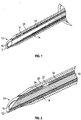
- the cannula 10 may include a distal tip 12, an elongated tubular shaft 14, and an inner lumen formed by the elongated tubular shaft 14.
- an optical fiber 16 may be at least partially disposed within the inner lumen of the cannula.
- the optical fiber 16 may include a distal end 18 and a proximal end (not illustrated in Figure 1 ).
- the optical fiber 16 may be configured to emit light from the distal end 18 and/or one or more notch features (not illustrated in Figure 1 ) defining discontinuities in the optical fiber 16.
- the notch features may be disposed at least proximate the distal end 18.
- the cannula 10 may include multiple optical fibers 16.
- the multiple optical fibers 16 may be aligned parallel to each other in the inner lumen of the cannula 10.
- the multiple optical fibers 16 may be twisted or braided together, which may increase a strength of the multiple optical fibers 16.
- the distal end 18 of the optical fiber 16 may be disposed at least proximate the distal tip 18 of the cannula 10, as illustrated in Figure 1 .
- the cannula 10 may be configured to light up or illuminate at least proximate the distal tip 18.
- a high intensity light source may be coupled with the proximal end of the optical fiber 16 and may produce the emitted light, which may be transmitted along the optical fiber 16 and emitted from the optical fiber 16.
- the emitted light may include one or more wavelengths of light.
- the emitted light may not include one or more particular wavelengths of light.
- the emitted light may not include the particular wavelengths corresponding to a color of blood or red, and when the emitted light shines on the blood within the blood vessel, the blood may not reflect the emitted light.
- the emitted light may not include red light having a light emission peak in wavelengths of 640 to 680 nanometers.
- the emitted light which may not include red light, may include one or more other particular wavelengths of light, which may correspond to a color of tissue and/or skin of the patient. The other particular wavelengths of light may be reflected by tissue and/or skin of the patient.
- tissue and/or the skin may be illuminated and may reflect the emitted light, but when the distal tip 12 of the cannula 10 reaches the blood vessel, the blood in the blood vessel may not reflect the emitted light.
- the clinician in response to the blood not reflecting the emitted light, when the distal tip 12 of the cannula 10 is positioned within the blood vessel, the clinician may observe darkness as opposed to light at a location of the blood vessel. A change from light to the darkness as the cannula 10 moves from the skin and/or the tissue to within the blood vessel may provide a visual cue to the clinician that the distal tip 12 of the cannula 10 is positioned within the blood vessel.
- a distal end of the catheter may be disposed proximate the distal tip. Thus, the position of the distal tip of the cannula 10 may approximate a position of the catheter 20 through which the cannula 10 may extend.
- the emitted light may not include one or more wavelengths of light corresponding to a color of the tissue and/or the skin.
- the emitted light may include red light, corresponding to the color of blood.
- the tissue and/or the skin may reflect the emitted light at a reduced level compared to the blood or not at all.
- the blood in the blood vessel may reflect the emitted light and may be illuminated when the emitted light is shined on the blood.
- the illumination of the blood may indicate the distal tip 12 of the cannula 10 is positioned within the blood vessel.
- the illumination of the blood in the blood vessel may facilitate an increase in an intensity of light seen by the clinician and reflected from anatomy of the patient (blood vessel, tissue, skin, etc. ) .
- the clinician may see a reduced intensity of light or no light reflected from the tissue and/or the skin as the cannula 10 is advanced, and then in response to the cannula 10 reaching the blood of the blood vessel, the increase in the intensity of light may occur as the blood vessel is illuminated.
- the blood vessel when the optical fiber 16 illuminates the blood in the blood vessel, the blood vessel may act as a light pipe and the emitted light may be distributed throughout a length of the blood vessel, which may signal to the clinician that the cannula 10 is positioned within the blood vessel.
- the blood vessel when the optical fiber 16 illuminates the blood in the blood vessel, the blood vessel may be seen through the skin of the patient, providing a visual cue to the clinician as to a position of the distal tip 12 of the cannula 10.
- the tissue when the optical fiber 16 illuminates the tissue of the patient, the tissue may be seen through the skin of the patient, providing a visual cue to the clinician as to the position of the distal tip 12 of the cannula 10.
- the cannula 10 comprises opening 22 in the elongated shaft 14.
- the opening 22 is disposed towards the distal tip 12 of the cannula 10.
- the optical fiber 16 includes one or more grooves 24, which extend from the distal end 18 of the optical fiber 16 to a portion of the optical fiber 16 aligned with the opening 22.
- the groove 24 is configured to allow blood to flow between the distal tip 12 and the opening 22.
- the blood may then flow out of the opening 22 and into a portion of the catheter device, such as the catheter 20 and/or a catheter adapter, for example, where the blood can be seen by the clinician, which may signal to the clinician that the cannula 10 is positioned within the blood vessel.
- the optical fiber 16 may allow continuous monitoring of the position of the cannula 10.
- the optical fiber 16 may indicate the cannula 10 has been inserted too far into the blood vessel and has transfixed the blood vessel. For example, in response to the emitted light including red light and not including a particular wavelength corresponding to a color of the tissue, the blood in the blood vessel may be illuminated when the emitted light is shined on the blood. However, if transfixing of the blood vessel occurs, less light than reflected by the blood or no light may be reflected by tissue of the blood vessel wall or tissue outside of the blood vessel wall, and the clinician may perceive darkness as opposed to light at a location of the tissue.
- the blood vessel may not reflect light and the clinician may perceive darkness as opposed to light at a location of the blood vessel.
- the tissue may illuminate, reflecting the emitted light, and the clinician may observe the illuminated tissue through the skin of the patient.
- the opening 22 of the cannula 10 may be eliminated, which may reduce manufacturing costs of the cannula 10.
- the cannula 10 may include both the opening 22 and the optical fiber 16, allowing dual mechanisms to detect entry of the distal tip 12 of the cannula 10 into the blood vessel.
- the optical fiber 16 may not move distally or proximally with respect to the cannula 10, and the optical fiber 16 and the cannula 10 may move together in the proximal and/or the distal direction.
- the optical fiber 16 and the cannula 10 may be configured in an interference fit.
- the optical fiber 16 may not move beyond the distal tip 12 of the cannula 10.
- a length of the optical fiber 16 may prevent the optical fiber 16 from moving beyond the distal tip 12 of the cannula 10.
- the optical fiber 16 may act similar to a guidewire.
- the optical fiber 16 may be configured to move past the distal tip 12 of the cannula 10 to guide a catheter 20 into the blood vessel 26 of the patient.
- the catheter 20 may follow the optical fiber 16 into the blood vessel 26 to reduce trauma to the blood vessel 26 during advancement of the catheter 20 into the blood vessel 26.
- the optical fiber 16 may not only reduce trauma to the blood vessel 26 by guiding the catheter 20 into the blood vessel 26, but may emit high-intensity light to illuminate the blood vessel 26, allowing the clinician to more clearly see a location of the blood vessel 26, which may aid in advancement of the catheter 20.
- the high-intensity light may be emitted from the distal end 18 and/or one or more other discontinuities in the optical fiber 16.
- the discontinuities may be disposed along an upper and/or lower surface of the optical fiber 16, as illustrated in Figure 3 .
- the discontinuities may be exposed when the optical fiber 16 moves past the distal tip 12 of the cannula 10.
- the illuminated blood vessel 26 may act as a light pipe and the emitted light may be distributed throughout a length of the blood vessel 26.
- the optical fiber 16 is configured to emit light from one or more notch features 28 of the optical fiber 16, each of the notch features 28 defining a discontinuity in the optical fiber 16.
- one or more of the notch features 28 of the optical fiber may be disposed towards the distal end 18 of the optical fiber.
- the notch features 28 of the optical fiber 16 may be exposed when the optical fiber 16 moves past the distal tip 12 of the cannula 10.
- the distal end 18 of the optical fiber may be rounded and/or smooth, which may allow the optical fiber 16 to enter the blood vessel 26 more smoothly and/or without puncturing the blood vessel 26.
- the rounded distal end 18 of the optical fiber 16 may also make it more difficult for the optical fiber 16 to transfix the blood vessel 26.
- the notch features 28 of the optical fiber 16 may have various configurations and arrangements.
- the notch features 28 may provide multiple locations for light to be emitted from the optical fiber 16.
- the distal end 18 of a particular optical fiber 16 may be configured to move past the distal tip 12 may be disposed within and/or at least proximate the distal tip 12 of the cannula 10, allowing the position of the cannula 10 to be determined, as previously described.
- the particular optical fiber 16 in response to the cannula 10 being positioned within the blood vessel 26, the particular optical fiber 16 may be advanced past the distal tip 12 of the cannula 10 to guide the catheter 20 into the blood vessel 26.
- a wavelength of the emitted light from the particular optical fiber may be tuned, in any of the ways previously described, to monitor and/or determine a position of the distal end 18 of the particular optical fiber 16 prior to and/or after advancement of the particular optical fiber 16 past the distal tip 12 of the cannula 10.
- the catheter device 30 may include any catheter device.
- a system 31 may include the catheter device 30 and a high-intensity light source 32.
- catheter devices may include both straight and ported catheters such as the AUTOGUARD TM shielded catheter commercially available from Becton, Dickinson, and Company, integrated and non-integrated peripheral intravenous catheters, winged needle sets, blood collection sets, an IV access set such as the BD NEXIVA TM Closed Intravenous (IV) Catheter system available from Becton, Dickinson, and Company, etc.
- the optical fiber 16 may extend through the catheter device 30 from a proximal end of the catheter device 30 to a distal end of the device or through a portion of the catheter device 30. In some embodiments, the optical fiber 16 may extend from at least proximate the distal tip, beyond a proximal end 33 of the cannula, and/or through an opening in the proximal end of the catheter device 30. In some embodiments, the optical fiber 16 may exit the proximal end of the catheter device and be coupled with the high-intensity light source 32.
- the cannula 10 may include a hypodermic needle such as, for example, an introducer needle. Further, the cannula 10 may be used in any suitable manner. For example, the cannula may be used during various medical procedures, such as, for example, an intravenous infusion, peripheral nerve block, blood draw, spinal tap, spinal anesthesia, or epidural. In these and other embodiments, the cannula 10 may be used with or without the catheter device 30.
- the high-intensity light source 32 may include a lamp, such as, for example, an arc lamp, a quartz halogen lamp, or any other type of high-intensity lamp.
- the high-intensity light source may include a laser, a high-intensity light-emitting diode (LED), or another high-intensity light source.
- a proximal end 34 of the optical fiber 16 may be uncoupled from the high-intensity light source 32 and disposed of after use.
- the optical fiber 16 may be disposed of with a catheter adapter 36 and/or a needle hub 38 of the catheter device 30, for example.
- an optical connector (not illustrated in Figure 5 ) may selectively couple the proximal end 34 of the optical fiber 16 to the high-intensity light source.
- the optical connector may be disposed in any number of positions. For example, the optical connector may be disposed at a proximal end of the catheter device 30.
- the catheter device 30 may include multiple optical fibers, which may be disposed within the cannula 10.
- multiple optical fibers 16 may emit light and/or may be used to guide the catheter 20.
- a method 100 of assisting introduction of the catheter 20 into the blood vessel 26 of the patient may begin at block 102.
- the cannula 10 may be inserted into the blood vessel 26.
- Block 102 may be followed by block 104.
- the optical fiber 16 may be advanced beyond the distal tip 12 of the cannula 10 such that a portion of the optical fiber 16 is disposed outside the cannula 10 and another portion of the optical fiber 16 is disposed within the cannula 10.
- the method 100 may include additional blocks.
- the optical fiber 16 may be modified in any suitable manner that allows it to fulfill its intended purpose.
- the cannula 10 and optical fiber 16 may be used in any suitable manner.
- the cannula 10 and optical fiber 16 may allow a clinician to appropriately position the distal tip 12 of the cannula 10 during various medical procedures, such as, for example, an intravenous infusion, blood draw, spinal tap, or epidural.
- the wavelength of the light may be tuned based on a color of a medium at a destination of the distal tip 12.
- system 31 may be modified in any suitable manner that allows it to fulfill its intended purpose.
- catheter device 30 may be modified in any suitable manner that allows it to fulfill its intended purpose.
Landscapes
- Health & Medical Sciences (AREA)
- Life Sciences & Earth Sciences (AREA)
- Animal Behavior & Ethology (AREA)
- General Health & Medical Sciences (AREA)
- Biophysics (AREA)
- Veterinary Medicine (AREA)
- Engineering & Computer Science (AREA)
- Biomedical Technology (AREA)
- Heart & Thoracic Surgery (AREA)
- Public Health (AREA)
- Hematology (AREA)
- Pathology (AREA)
- Medical Informatics (AREA)
- Physics & Mathematics (AREA)
- Surgery (AREA)
- Molecular Biology (AREA)
- Pulmonology (AREA)
- Anesthesiology (AREA)
- Vascular Medicine (AREA)
- Infusion, Injection, And Reservoir Apparatuses (AREA)
- Media Introduction/Drainage Providing Device (AREA)
- Measurement Of The Respiration, Hearing Ability, Form, And Blood Characteristics Of Living Organisms (AREA)
- Laser Surgery Devices (AREA)
- Eye Examination Apparatus (AREA)
Claims (8)
- Kathetervorrichtung (30) zur visuellen Identifizierung eines Blutgefäßes, mit:einer Kanüle (10), wobei die Kanüle eine distale Spitze (12), einen langgestreckten rohrförmigen Schaft (14), ein durch den langgestreckten rohrförmigen Schaft gebildetes inneres Lumen, und eine Öffnung (22) in dem langgestreckten rohrförmigen Schaft aufweist, die in Richtung der distalen Spitze der Kanüle angeordnet ist; undeiner Glasfaser (16), die in dem inneren Lumen der Kanüle angeordnet ist, wobei die optische Faser ein distales Ende (18) und ein proximales Ende aufweist, wobei die Glasfaser (16) eine Nut (24) aufweist, wobei die Nut (24) sich von dem distalen Ende (18) der optischen Faser (16) zu einem auf die Öffnung ausgerichteten Bereich der Glasfaser erstreckt, wobei die Nut (24) dazu ausgebildet ist, das Fließen von Blut zwischen der distalen Spitze und der Öffnung zu ermöglichen, und wobei die Glasfaser dazu ausgebildet ist, Licht aus einer oder mehreren Kerbeneinrichtungen (28) zu emittieren, die jeweils eine Unterbrechung in der Glasfaser bilden.
- Vorrichtung nach Anspruch 1, bei welcher das distale Ende der Glasfaser zumindest nahe der distalen Spitze der Kanüle angeordnet ist.
- Vorrichtung nach Anspruch 1 oder Anspruch 2, bei welcher das emittierte Licht kein Rotlicht mit einer Lichtemissionsspitze bei Wellenlängen von 640 bis 680 Nanometern aufweist.
- Vorrichtung nach Anspruch 1 oder Anspruch 2, bei welcher das emittierte Licht Rotlicht mit einer Lichtemissionsspitze bei Wellenlängen von 640 bis 680 Nanometern ist.
- Vorrichtung nach einem der Ansprüche 1 bis 4, bei welcher die Glasfaser dazu ausgebildet ist, sich an der distalen Spitze der Kanüle vorbei zu bewegen, um einen Katheter in das Blutgefäß zu führen.
- Vorrichtung nach einem der Ansprüche 1 bis 5, bei welcher das distale Ende der Glasfaser abgerundet ist.
- Vorrichtung nach einem der Ansprüche 1 bis 6, bei welcher die eine oder die mehreren Kerbeneinrichtungen zumindest nahe dem Ende der Glasfaser angeordnet sind.
- Vorrichtung nach einem der Ansprüche 1 bis 7, bei welcher die Glasfaser und die Kanüle in einer Presspassung ausgebildet sind.
Applications Claiming Priority (4)
| Application Number | Priority Date | Filing Date | Title |
|---|---|---|---|
| US201662314258P | 2016-03-28 | 2016-03-28 | |
| US15/461,354 US10835718B2 (en) | 2016-03-28 | 2017-03-16 | Cannula with light-emitting optical fiber |
| EP17714364.1A EP3435842B1 (de) | 2016-03-28 | 2017-03-17 | Kanüle mit lichtemittierender glasfaser |
| PCT/US2017/022928 WO2017172385A1 (en) | 2016-03-28 | 2017-03-17 | Cannula with light-emitting optical fiber |
Related Parent Applications (2)
| Application Number | Title | Priority Date | Filing Date |
|---|---|---|---|
| EP17714364.1A Division EP3435842B1 (de) | 2016-03-28 | 2017-03-17 | Kanüle mit lichtemittierender glasfaser |
| EP17714364.1A Division-Into EP3435842B1 (de) | 2016-03-28 | 2017-03-17 | Kanüle mit lichtemittierender glasfaser |
Publications (2)
| Publication Number | Publication Date |
|---|---|
| EP3788951A1 EP3788951A1 (de) | 2021-03-10 |
| EP3788951B1 true EP3788951B1 (de) | 2023-01-04 |
Family
ID=59896736
Family Applications (2)
| Application Number | Title | Priority Date | Filing Date |
|---|---|---|---|
| EP20195892.3A Active EP3788951B1 (de) | 2016-03-28 | 2017-03-17 | Kanüle mit lichtemittierender glasfaser |
| EP17714364.1A Active EP3435842B1 (de) | 2016-03-28 | 2017-03-17 | Kanüle mit lichtemittierender glasfaser |
Family Applications After (1)
| Application Number | Title | Priority Date | Filing Date |
|---|---|---|---|
| EP17714364.1A Active EP3435842B1 (de) | 2016-03-28 | 2017-03-17 | Kanüle mit lichtemittierender glasfaser |
Country Status (9)
| Country | Link |
|---|---|
| US (2) | US10835718B2 (de) |
| EP (2) | EP3788951B1 (de) |
| JP (2) | JP6734392B2 (de) |
| CN (2) | CN113082454B (de) |
| AU (2) | AU2017240484B2 (de) |
| CA (1) | CA3018172C (de) |
| ES (2) | ES2846888T3 (de) |
| SG (1) | SG11201808300UA (de) |
| WO (1) | WO2017172385A1 (de) |
Families Citing this family (7)
| Publication number | Priority date | Publication date | Assignee | Title |
|---|---|---|---|---|
| US11478150B2 (en) | 2016-03-28 | 2022-10-25 | Becton, Dickinson And Company | Optical fiber sensor |
| US10850046B2 (en) | 2016-03-28 | 2020-12-01 | Becton, Dickinson And Company | Cannula locator device |
| US10835718B2 (en) | 2016-03-28 | 2020-11-17 | Becton, Dickinson And Company | Cannula with light-emitting optical fiber |
| KR102166115B1 (ko) * | 2018-11-19 | 2020-10-15 | 이선주 | 빛이 나오는 주사기 |
| EP3905944B1 (de) * | 2019-01-02 | 2025-06-04 | Acera LLC | Positionierung eines schlauches in einem lumen mittels durchleuchtung |
| JPWO2020202742A1 (de) * | 2019-03-29 | 2020-10-08 | ||
| CN110718130B (zh) * | 2019-10-31 | 2022-05-20 | 河南省人民医院 | 一种护理教学用静脉注射模型 |
Family Cites Families (60)
| Publication number | Priority date | Publication date | Assignee | Title |
|---|---|---|---|---|
| US3789841A (en) | 1971-09-15 | 1974-02-05 | Becton Dickinson Co | Disposable guide wire |
| US4317445A (en) | 1980-03-31 | 1982-03-02 | Baxter Travenol Laboratories, Inc. | Catheter insertion unit with separate flashback indication for the cannula |
| GB8431680D0 (en) | 1984-12-17 | 1985-01-30 | Bellhouse Medical Products Ltd | Fibre optic sensor |
| US4682895A (en) | 1985-08-06 | 1987-07-28 | Texas A&M University | Fiber optic probe for quantification of colorimetric reactions |
| US4800886A (en) | 1986-07-14 | 1989-01-31 | C. R. Bard, Inc. | Sensor for measuring the concentration of a gaseous component in a fluid by absorption |
| US5092845A (en) | 1989-07-10 | 1992-03-03 | Critikon, Inc. | Catheter with needle gasket |
| US5124130A (en) | 1990-05-22 | 1992-06-23 | Optex Biomedical, Inc. | Optical probe |
| US5054882A (en) | 1990-08-10 | 1991-10-08 | Puritan-Bennett Corporation | Multiple optical fiber event sensor and method of manufacture |
| US5271398A (en) | 1991-10-09 | 1993-12-21 | Optex Biomedical, Inc. | Intra-vessel measurement of blood parameters |
| US5779680A (en) | 1991-11-27 | 1998-07-14 | Yoon; Inbae | Retractable safety needle instrument with movable safety member |
| US5460182A (en) | 1992-09-14 | 1995-10-24 | Sextant Medical Corporation | Tissue penetrating apparatus and methods |
| US5452076A (en) | 1993-09-29 | 1995-09-19 | Optiguard, Inc. | Fluid detection system |
| JP3079347B2 (ja) | 1994-07-15 | 2000-08-21 | 東京特殊電線株式会社 | 接触型光ファイバセンサおよび流れの測定方法および装置 |
| JP3636747B2 (ja) | 1994-11-09 | 2005-04-06 | テルモ株式会社 | 医療用カテーテル |
| US5772636A (en) * | 1996-12-02 | 1998-06-30 | Becton Dickinson And Company | Catheter assembly with interlocking telescoping needle shield |
| US20030120214A1 (en) | 2001-03-28 | 2003-06-26 | Howell Glade H. | Blood seal having a spring-biased septum |
| US20060264745A1 (en) | 2003-03-17 | 2006-11-23 | Da Silva Luiz B | Optical biopsy system with single use needle probe |
| US7496392B2 (en) | 2003-11-26 | 2009-02-24 | Becton, Dickinson And Company | Fiber optic device for sensing analytes |
| US7787923B2 (en) * | 2003-11-26 | 2010-08-31 | Becton, Dickinson And Company | Fiber optic device for sensing analytes and method of making same |
| SE0401632D0 (sv) | 2004-06-24 | 2004-06-24 | Innovation Team Ab | Medel och sätt att detektera blodläckage från sår |
| US20060167405A1 (en) | 2004-12-13 | 2006-07-27 | Medex, Inc. | Bodily fluid space entry detection |
| US7860555B2 (en) | 2005-02-02 | 2010-12-28 | Voyage Medical, Inc. | Tissue visualization and manipulation system |
| WO2006122061A1 (en) | 2005-05-06 | 2006-11-16 | Acumen Medical, Inc. | Complexly shaped steerable catheters and methods for making and using them |
| US8954134B2 (en) * | 2005-09-13 | 2015-02-10 | Children's Medical Center Corporation | Light-guided transluminal catheter |
| US20070073160A1 (en) * | 2005-09-13 | 2007-03-29 | Children's Medical Center Corporation | Light-guided transluminal catheter |
| WO2008008318A2 (en) | 2006-07-10 | 2008-01-17 | Boston Scientific Limited | Optical spectroscopic injection needle |
| US10534129B2 (en) | 2007-03-30 | 2020-01-14 | The General Hospital Corporation | System and method providing intracoronary laser speckle imaging for the detection of vulnerable plaque |
| US8840566B2 (en) | 2007-04-02 | 2014-09-23 | University Of Washington | Catheter with imaging capability acts as guidewire for cannula tools |
| SE531750C2 (sv) | 2007-04-04 | 2009-07-28 | Redsense Medical Malta Ltd | Anordning för detektering av blodläckage |
| EP2249737B1 (de) | 2008-03-03 | 2020-07-01 | Koninklijke Philips N.V. | Biopsie-führung mithilfe elektromagnetischer verfolgung und einer photonischen nadel |
| US20110009772A1 (en) * | 2008-03-18 | 2011-01-13 | Koninklijke Philips Electronics N.V. | Biopsy device |
| US8109909B2 (en) * | 2008-03-31 | 2012-02-07 | Terumo Kabushiki Kaisha | Medical instrument |
| US10092315B2 (en) | 2008-07-28 | 2018-10-09 | Expanding Innovations, Inc. | Penetrating member with direct visualization |
| US20100081873A1 (en) | 2008-09-30 | 2010-04-01 | AiHeart Medical Technologies, Inc. | Systems and methods for optical viewing and therapeutic intervention in blood vessels |
| EP2376960A1 (de) * | 2008-12-22 | 2011-10-19 | AMS Research Corporation | Auf saphier basierende verabreichungsspitze für optische faser |
| US9339221B1 (en) | 2009-03-24 | 2016-05-17 | Vioptix, Inc. | Diagnosing intestinal ischemia based on oxygen saturation measurements |
| US9737213B1 (en) | 2009-03-24 | 2017-08-22 | Vioptix, Inc. | Using an oximeter probe to detect intestinal ischemia |
| CN102458229B (zh) | 2009-06-10 | 2015-07-22 | 皇家飞利浦电子股份有限公司 | 用于光子针控制台的算法 |
| EP2467057B1 (de) | 2009-08-19 | 2020-07-22 | Medline Industries, Inc., | System und vorrichtung zur erleichterung des zugriffs auf anatomische zielstandorte oder -umgebungen |
| US20110077477A1 (en) * | 2009-09-30 | 2011-03-31 | Glumetrics, Inc. | Sensors with thromboresistant coating |
| US8597252B2 (en) | 2010-07-15 | 2013-12-03 | Becton, Dickinson And Company | Removable flash chamber |
| EP2625505A1 (de) | 2010-10-08 | 2013-08-14 | Edwards Lifesciences Corporation | Kontinuierliche messung des gesamthämoglobins |
| EP2667816A2 (de) | 2011-01-28 | 2013-12-04 | Koninklijke Philips N.V. | Formspeichernde glasfaser zur spitzen- und formcharakterisierung medizinischer instrumente |
| CN103339485B (zh) | 2011-01-28 | 2015-12-02 | 皇家飞利浦电子股份有限公司 | 外科末端执行器附近的外来对象的探测 |
| US8323181B2 (en) | 2011-02-17 | 2012-12-04 | Apurba Mukherjee | Endoscope with variable incident light and laser source platform |
| US9267906B2 (en) | 2011-04-12 | 2016-02-23 | The Boeing Company | Bondline embedded current sensor |
| US9247906B2 (en) * | 2011-06-28 | 2016-02-02 | Christie Digital Systems Usa, Inc. | Method and apparatus for detection of catheter location for intravenous access |
| US9700697B2 (en) * | 2012-08-21 | 2017-07-11 | Optomeditech Oy | Intravascular catheter assembly |
| CN102929070B (zh) * | 2012-11-19 | 2016-01-20 | 南京大学(苏州)高新技术研究院 | 一种提高微光纤表面二次谐波转换效率的结构 |
| CN203169779U (zh) * | 2013-02-05 | 2013-09-04 | 于冬男 | 一种基于光纤可视化技术的气管插管辅助装置 |
| US20140276024A1 (en) | 2013-03-12 | 2014-09-18 | Volcano Corporation | Imaging and delivering thrombolytic agents to biological material inside a vessel |
| WO2015056257A1 (en) | 2013-10-14 | 2015-04-23 | Avraham Aharoni | Device and system for imaging veins |
| EP3091906A4 (de) | 2014-01-10 | 2017-01-11 | Volcano Corporation | Nachweis von endolecks im zusammenhang mit der reparatur eines aneurysmas |
| WO2015163942A1 (en) | 2014-04-23 | 2015-10-29 | Calcula Technologies, Inc. | Integrated medical imaging system |
| ES2747649T3 (es) | 2014-05-02 | 2020-03-11 | Bard Inc C R | Dispositivo de colocación de catéter que incluye elementos de control de catéter e hilo guía |
| WO2015200712A1 (en) | 2014-06-25 | 2015-12-30 | Massachusetts Institute Of Technology | Optical sensor for needle-tip tissue identification and diagnosis |
| EP3190979B1 (de) | 2014-09-09 | 2019-07-31 | Intuitive Surgical Operations, Inc. | System mit führungen und werkzeuge mit verschiedener nachgiebigkeit |
| US10850046B2 (en) | 2016-03-28 | 2020-12-01 | Becton, Dickinson And Company | Cannula locator device |
| US10835718B2 (en) | 2016-03-28 | 2020-11-17 | Becton, Dickinson And Company | Cannula with light-emitting optical fiber |
| KR102040884B1 (ko) * | 2017-06-12 | 2019-11-06 | 주식회사 크림슨스타 | 감염방지 카테터 |
-
2017
- 2017-03-16 US US15/461,354 patent/US10835718B2/en active Active
- 2017-03-17 CN CN202110421574.6A patent/CN113082454B/zh active Active
- 2017-03-17 CN CN201780020794.XA patent/CN108882863B/zh active Active
- 2017-03-17 ES ES17714364T patent/ES2846888T3/es active Active
- 2017-03-17 ES ES20195892T patent/ES2939538T3/es active Active
- 2017-03-17 EP EP20195892.3A patent/EP3788951B1/de active Active
- 2017-03-17 JP JP2018551259A patent/JP6734392B2/ja active Active
- 2017-03-17 SG SG11201808300UA patent/SG11201808300UA/en unknown
- 2017-03-17 WO PCT/US2017/022928 patent/WO2017172385A1/en not_active Ceased
- 2017-03-17 EP EP17714364.1A patent/EP3435842B1/de active Active
- 2017-03-17 CA CA3018172A patent/CA3018172C/en active Active
- 2017-03-17 AU AU2017240484A patent/AU2017240484B2/en active Active
-
2019
- 2019-12-30 AU AU2019284141A patent/AU2019284141B2/en active Active
-
2020
- 2020-07-09 JP JP2020118621A patent/JP7354062B2/ja active Active
- 2020-10-15 US US17/071,776 patent/US12251528B2/en active Active
Also Published As
| Publication number | Publication date |
|---|---|
| EP3435842A1 (de) | 2019-02-06 |
| CN108882863A (zh) | 2018-11-23 |
| BR112018069746A8 (pt) | 2023-03-07 |
| CN108882863B (zh) | 2021-05-07 |
| ES2939538T3 (es) | 2023-04-24 |
| JP2019516430A (ja) | 2019-06-20 |
| US20170274184A1 (en) | 2017-09-28 |
| AU2017240484A1 (en) | 2018-10-25 |
| EP3788951A1 (de) | 2021-03-10 |
| CN113082454B (zh) | 2022-12-30 |
| US10835718B2 (en) | 2020-11-17 |
| US12251528B2 (en) | 2025-03-18 |
| AU2019284141A1 (en) | 2020-01-30 |
| SG11201808300UA (en) | 2018-10-30 |
| BR112018069746A2 (pt) | 2019-02-05 |
| ES2846888T3 (es) | 2021-07-30 |
| JP2020179202A (ja) | 2020-11-05 |
| CA3018172A1 (en) | 2017-10-05 |
| EP3435842B1 (de) | 2020-11-11 |
| JP6734392B2 (ja) | 2020-08-05 |
| US20210023345A1 (en) | 2021-01-28 |
| JP7354062B2 (ja) | 2023-10-02 |
| CA3018172C (en) | 2021-01-12 |
| CN113082454A (zh) | 2021-07-09 |
| WO2017172385A1 (en) | 2017-10-05 |
| AU2019284141B2 (en) | 2020-07-30 |
| AU2017240484B2 (en) | 2019-10-10 |
Similar Documents
| Publication | Publication Date | Title |
|---|---|---|
| US12251528B2 (en) | Cannula with light-emitting optical fiber | |
| US12544517B2 (en) | Cannula locator device | |
| US10602960B2 (en) | Locating device | |
| EP1931273B1 (de) | Lichtgeführter transluminaler katheter | |
| US20200197682A1 (en) | Access device with guidewire and related methods | |
| AU2017204183A1 (en) | Handheld Multi-Needle Vascular Access Device | |
| BR112018069746B1 (pt) | Dispositivo de cateter para identificar visualmente um vaso sanguíneo e método para auxiliar a introdução de um cateter |
Legal Events
| Date | Code | Title | Description |
|---|---|---|---|
| PUAI | Public reference made under article 153(3) epc to a published international application that has entered the european phase |
Free format text: ORIGINAL CODE: 0009012 |
|
| STAA | Information on the status of an ep patent application or granted ep patent |
Free format text: STATUS: THE APPLICATION HAS BEEN PUBLISHED |
|
| AC | Divisional application: reference to earlier application |
Ref document number: 3435842 Country of ref document: EP Kind code of ref document: P |
|
| AK | Designated contracting states |
Kind code of ref document: A1 Designated state(s): AL AT BE BG CH CY CZ DE DK EE ES FI FR GB GR HR HU IE IS IT LI LT LU LV MC MK MT NL NO PL PT RO RS SE SI SK SM TR |
|
| STAA | Information on the status of an ep patent application or granted ep patent |
Free format text: STATUS: REQUEST FOR EXAMINATION WAS MADE |
|
| 17P | Request for examination filed |
Effective date: 20210907 |
|
| RBV | Designated contracting states (corrected) |
Designated state(s): AL AT BE BG CH CY CZ DE DK EE ES FI FR GB GR HR HU IE IS IT LI LT LU LV MC MK MT NL NO PL PT RO RS SE SI SK SM TR |
|
| STAA | Information on the status of an ep patent application or granted ep patent |
Free format text: STATUS: EXAMINATION IS IN PROGRESS |
|
| 17Q | First examination report despatched |
Effective date: 20220113 |
|
| GRAP | Despatch of communication of intention to grant a patent |
Free format text: ORIGINAL CODE: EPIDOSNIGR1 |
|
| STAA | Information on the status of an ep patent application or granted ep patent |
Free format text: STATUS: GRANT OF PATENT IS INTENDED |
|
| RIN1 | Information on inventor provided before grant (corrected) |
Inventor name: BURKHOLZ, JONATHAN KARL Inventor name: SONDEREGGER, RALPH L. Inventor name: ISAACSON, S. RAY |
|
| INTG | Intention to grant announced |
Effective date: 20220720 |
|
| GRAS | Grant fee paid |
Free format text: ORIGINAL CODE: EPIDOSNIGR3 |
|
| GRAA | (expected) grant |
Free format text: ORIGINAL CODE: 0009210 |
|
| STAA | Information on the status of an ep patent application or granted ep patent |
Free format text: STATUS: THE PATENT HAS BEEN GRANTED |
|
| AC | Divisional application: reference to earlier application |
Ref document number: 3435842 Country of ref document: EP Kind code of ref document: P |
|
| AK | Designated contracting states |
Kind code of ref document: B1 Designated state(s): AL AT BE BG CH CY CZ DE DK EE ES FI FR GB GR HR HU IE IS IT LI LT LU LV MC MK MT NL NO PL PT RO RS SE SI SK SM TR |
|
| REG | Reference to a national code |
Ref country code: GB Ref legal event code: FG4D |
|
| REG | Reference to a national code |
Ref country code: CH Ref legal event code: EP |
|
| REG | Reference to a national code |
Ref country code: AT Ref legal event code: REF Ref document number: 1541364 Country of ref document: AT Kind code of ref document: T Effective date: 20230115 |
|
| REG | Reference to a national code |
Ref country code: DE Ref legal event code: R096 Ref document number: 602017065345 Country of ref document: DE |
|
| REG | Reference to a national code |
Ref country code: IE Ref legal event code: FG4D |
|
| REG | Reference to a national code |
Ref country code: ES Ref legal event code: FG2A Ref document number: 2939538 Country of ref document: ES Kind code of ref document: T3 Effective date: 20230424 |
|
| REG | Reference to a national code |
Ref country code: LT Ref legal event code: MG9D |
|
| REG | Reference to a national code |
Ref country code: NL Ref legal event code: MP Effective date: 20230104 |
|
| REG | Reference to a national code |
Ref country code: AT Ref legal event code: MK05 Ref document number: 1541364 Country of ref document: AT Kind code of ref document: T Effective date: 20230104 |
|
| PG25 | Lapsed in a contracting state [announced via postgrant information from national office to epo] |
Ref country code: NL Free format text: LAPSE BECAUSE OF FAILURE TO SUBMIT A TRANSLATION OF THE DESCRIPTION OR TO PAY THE FEE WITHIN THE PRESCRIBED TIME-LIMIT Effective date: 20230104 |
|
| PG25 | Lapsed in a contracting state [announced via postgrant information from national office to epo] |
Ref country code: RS Free format text: LAPSE BECAUSE OF FAILURE TO SUBMIT A TRANSLATION OF THE DESCRIPTION OR TO PAY THE FEE WITHIN THE PRESCRIBED TIME-LIMIT Effective date: 20230104 Ref country code: PT Free format text: LAPSE BECAUSE OF FAILURE TO SUBMIT A TRANSLATION OF THE DESCRIPTION OR TO PAY THE FEE WITHIN THE PRESCRIBED TIME-LIMIT Effective date: 20230504 Ref country code: NO Free format text: LAPSE BECAUSE OF FAILURE TO SUBMIT A TRANSLATION OF THE DESCRIPTION OR TO PAY THE FEE WITHIN THE PRESCRIBED TIME-LIMIT Effective date: 20230404 Ref country code: LV Free format text: LAPSE BECAUSE OF FAILURE TO SUBMIT A TRANSLATION OF THE DESCRIPTION OR TO PAY THE FEE WITHIN THE PRESCRIBED TIME-LIMIT Effective date: 20230104 Ref country code: LT Free format text: LAPSE BECAUSE OF FAILURE TO SUBMIT A TRANSLATION OF THE DESCRIPTION OR TO PAY THE FEE WITHIN THE PRESCRIBED TIME-LIMIT Effective date: 20230104 Ref country code: HR Free format text: LAPSE BECAUSE OF FAILURE TO SUBMIT A TRANSLATION OF THE DESCRIPTION OR TO PAY THE FEE WITHIN THE PRESCRIBED TIME-LIMIT Effective date: 20230104 Ref country code: AT Free format text: LAPSE BECAUSE OF FAILURE TO SUBMIT A TRANSLATION OF THE DESCRIPTION OR TO PAY THE FEE WITHIN THE PRESCRIBED TIME-LIMIT Effective date: 20230104 |
|
| PG25 | Lapsed in a contracting state [announced via postgrant information from national office to epo] |
Ref country code: SE Free format text: LAPSE BECAUSE OF FAILURE TO SUBMIT A TRANSLATION OF THE DESCRIPTION OR TO PAY THE FEE WITHIN THE PRESCRIBED TIME-LIMIT Effective date: 20230104 Ref country code: PL Free format text: LAPSE BECAUSE OF FAILURE TO SUBMIT A TRANSLATION OF THE DESCRIPTION OR TO PAY THE FEE WITHIN THE PRESCRIBED TIME-LIMIT Effective date: 20230104 Ref country code: IS Free format text: LAPSE BECAUSE OF FAILURE TO SUBMIT A TRANSLATION OF THE DESCRIPTION OR TO PAY THE FEE WITHIN THE PRESCRIBED TIME-LIMIT Effective date: 20230504 Ref country code: GR Free format text: LAPSE BECAUSE OF FAILURE TO SUBMIT A TRANSLATION OF THE DESCRIPTION OR TO PAY THE FEE WITHIN THE PRESCRIBED TIME-LIMIT Effective date: 20230405 Ref country code: FI Free format text: LAPSE BECAUSE OF FAILURE TO SUBMIT A TRANSLATION OF THE DESCRIPTION OR TO PAY THE FEE WITHIN THE PRESCRIBED TIME-LIMIT Effective date: 20230104 |
|
| REG | Reference to a national code |
Ref country code: DE Ref legal event code: R097 Ref document number: 602017065345 Country of ref document: DE |
|
| PG25 | Lapsed in a contracting state [announced via postgrant information from national office to epo] |
Ref country code: SM Free format text: LAPSE BECAUSE OF FAILURE TO SUBMIT A TRANSLATION OF THE DESCRIPTION OR TO PAY THE FEE WITHIN THE PRESCRIBED TIME-LIMIT Effective date: 20230104 Ref country code: RO Free format text: LAPSE BECAUSE OF FAILURE TO SUBMIT A TRANSLATION OF THE DESCRIPTION OR TO PAY THE FEE WITHIN THE PRESCRIBED TIME-LIMIT Effective date: 20230104 Ref country code: MC Free format text: LAPSE BECAUSE OF FAILURE TO SUBMIT A TRANSLATION OF THE DESCRIPTION OR TO PAY THE FEE WITHIN THE PRESCRIBED TIME-LIMIT Effective date: 20230104 Ref country code: EE Free format text: LAPSE BECAUSE OF FAILURE TO SUBMIT A TRANSLATION OF THE DESCRIPTION OR TO PAY THE FEE WITHIN THE PRESCRIBED TIME-LIMIT Effective date: 20230104 Ref country code: DK Free format text: LAPSE BECAUSE OF FAILURE TO SUBMIT A TRANSLATION OF THE DESCRIPTION OR TO PAY THE FEE WITHIN THE PRESCRIBED TIME-LIMIT Effective date: 20230104 Ref country code: CZ Free format text: LAPSE BECAUSE OF FAILURE TO SUBMIT A TRANSLATION OF THE DESCRIPTION OR TO PAY THE FEE WITHIN THE PRESCRIBED TIME-LIMIT Effective date: 20230104 |
|
| REG | Reference to a national code |
Ref country code: CH Ref legal event code: PL |
|
| PLBE | No opposition filed within time limit |
Free format text: ORIGINAL CODE: 0009261 |
|
| STAA | Information on the status of an ep patent application or granted ep patent |
Free format text: STATUS: NO OPPOSITION FILED WITHIN TIME LIMIT |
|
| PG25 | Lapsed in a contracting state [announced via postgrant information from national office to epo] |
Ref country code: SK Free format text: LAPSE BECAUSE OF FAILURE TO SUBMIT A TRANSLATION OF THE DESCRIPTION OR TO PAY THE FEE WITHIN THE PRESCRIBED TIME-LIMIT Effective date: 20230104 |
|
| 26N | No opposition filed |
Effective date: 20231005 |
|
| PG25 | Lapsed in a contracting state [announced via postgrant information from national office to epo] |
Ref country code: LU Free format text: LAPSE BECAUSE OF NON-PAYMENT OF DUE FEES Effective date: 20230317 |
|
| REG | Reference to a national code |
Ref country code: IE Ref legal event code: MM4A |
|
| PG25 | Lapsed in a contracting state [announced via postgrant information from national office to epo] |
Ref country code: SI Free format text: LAPSE BECAUSE OF FAILURE TO SUBMIT A TRANSLATION OF THE DESCRIPTION OR TO PAY THE FEE WITHIN THE PRESCRIBED TIME-LIMIT Effective date: 20230104 Ref country code: LI Free format text: LAPSE BECAUSE OF NON-PAYMENT OF DUE FEES Effective date: 20230331 Ref country code: IE Free format text: LAPSE BECAUSE OF NON-PAYMENT OF DUE FEES Effective date: 20230317 Ref country code: CH Free format text: LAPSE BECAUSE OF NON-PAYMENT OF DUE FEES Effective date: 20230331 |
|
| PG25 | Lapsed in a contracting state [announced via postgrant information from national office to epo] |
Ref country code: BG Free format text: LAPSE BECAUSE OF FAILURE TO SUBMIT A TRANSLATION OF THE DESCRIPTION OR TO PAY THE FEE WITHIN THE PRESCRIBED TIME-LIMIT Effective date: 20230104 |
|
| PG25 | Lapsed in a contracting state [announced via postgrant information from national office to epo] |
Ref country code: BG Free format text: LAPSE BECAUSE OF FAILURE TO SUBMIT A TRANSLATION OF THE DESCRIPTION OR TO PAY THE FEE WITHIN THE PRESCRIBED TIME-LIMIT Effective date: 20230104 |
|
| PGFP | Annual fee paid to national office [announced via postgrant information from national office to epo] |
Ref country code: ES Payment date: 20250401 Year of fee payment: 9 |
|
| PG25 | Lapsed in a contracting state [announced via postgrant information from national office to epo] |
Ref country code: CY Free format text: LAPSE BECAUSE OF FAILURE TO SUBMIT A TRANSLATION OF THE DESCRIPTION OR TO PAY THE FEE WITHIN THE PRESCRIBED TIME-LIMIT; INVALID AB INITIO Effective date: 20170317 |
|
| PG25 | Lapsed in a contracting state [announced via postgrant information from national office to epo] |
Ref country code: HU Free format text: LAPSE BECAUSE OF FAILURE TO SUBMIT A TRANSLATION OF THE DESCRIPTION OR TO PAY THE FEE WITHIN THE PRESCRIBED TIME-LIMIT; INVALID AB INITIO Effective date: 20170317 |
|
| PG25 | Lapsed in a contracting state [announced via postgrant information from national office to epo] |
Ref country code: TR Free format text: LAPSE BECAUSE OF FAILURE TO SUBMIT A TRANSLATION OF THE DESCRIPTION OR TO PAY THE FEE WITHIN THE PRESCRIBED TIME-LIMIT Effective date: 20230104 |
|
| PGFP | Annual fee paid to national office [announced via postgrant information from national office to epo] |
Ref country code: GB Payment date: 20260220 Year of fee payment: 10 |
|
| PGFP | Annual fee paid to national office [announced via postgrant information from national office to epo] |
Ref country code: DE Payment date: 20260219 Year of fee payment: 10 |
|
| PGFP | Annual fee paid to national office [announced via postgrant information from national office to epo] |
Ref country code: IT Payment date: 20260219 Year of fee payment: 10 Ref country code: BE Payment date: 20260219 Year of fee payment: 10 |
|
| PGFP | Annual fee paid to national office [announced via postgrant information from national office to epo] |
Ref country code: FR Payment date: 20260219 Year of fee payment: 10 |