EP3789104A1 - Verfahren und system zur filtration einer flüssigkeit - Google Patents
Verfahren und system zur filtration einer flüssigkeit Download PDFInfo
- Publication number
- EP3789104A1 EP3789104A1 EP19382783.9A EP19382783A EP3789104A1 EP 3789104 A1 EP3789104 A1 EP 3789104A1 EP 19382783 A EP19382783 A EP 19382783A EP 3789104 A1 EP3789104 A1 EP 3789104A1
- Authority
- EP
- European Patent Office
- Prior art keywords
- filtration
- fouling
- filtration system
- permeability
- operational mode
- Prior art date
- Legal status (The legal status is an assumption and is not a legal conclusion. Google has not performed a legal analysis and makes no representation as to the accuracy of the status listed.)
- Withdrawn
Links
- 238000001914 filtration Methods 0.000 title claims abstract description 180
- 238000000034 method Methods 0.000 title claims abstract description 57
- 239000007788 liquid Substances 0.000 title claims abstract description 23
- 230000004907 flux Effects 0.000 claims abstract description 37
- 230000009471 action Effects 0.000 claims abstract description 31
- 230000035699 permeability Effects 0.000 claims description 67
- 238000004140 cleaning Methods 0.000 claims description 54
- 239000000126 substance Substances 0.000 claims description 39
- 238000004519 manufacturing process Methods 0.000 claims description 37
- 230000002427 irreversible effect Effects 0.000 claims description 25
- 238000005265 energy consumption Methods 0.000 claims description 14
- 238000013213 extrapolation Methods 0.000 claims description 9
- 238000004891 communication Methods 0.000 claims description 2
- 239000012528 membrane Substances 0.000 description 51
- 239000012466 permeate Substances 0.000 description 12
- XLYOFNOQVPJJNP-UHFFFAOYSA-N water Substances O XLYOFNOQVPJJNP-UHFFFAOYSA-N 0.000 description 12
- 230000002441 reversible effect Effects 0.000 description 7
- 238000000108 ultra-filtration Methods 0.000 description 7
- 101100400452 Caenorhabditis elegans map-2 gene Proteins 0.000 description 6
- 101150064138 MAP1 gene Proteins 0.000 description 6
- 238000011001 backwashing Methods 0.000 description 6
- 238000012417 linear regression Methods 0.000 description 5
- 238000012423 maintenance Methods 0.000 description 5
- 238000004364 calculation method Methods 0.000 description 4
- 238000009285 membrane fouling Methods 0.000 description 4
- 238000012544 monitoring process Methods 0.000 description 4
- 238000011084 recovery Methods 0.000 description 4
- 238000005516 engineering process Methods 0.000 description 3
- 238000005374 membrane filtration Methods 0.000 description 3
- 238000001471 micro-filtration Methods 0.000 description 3
- 238000004458 analytical method Methods 0.000 description 2
- 238000013473 artificial intelligence Methods 0.000 description 2
- 238000011217 control strategy Methods 0.000 description 2
- 238000011161 development Methods 0.000 description 2
- 230000000694 effects Effects 0.000 description 2
- 239000011159 matrix material Substances 0.000 description 2
- 238000005259 measurement Methods 0.000 description 2
- 238000009287 sand filtration Methods 0.000 description 2
- 238000009991 scouring Methods 0.000 description 2
- MWRWFPQBGSZWNV-UHFFFAOYSA-N Dinitrosopentamethylenetetramine Chemical compound C1N2CN(N=O)CN1CN(N=O)C2 MWRWFPQBGSZWNV-UHFFFAOYSA-N 0.000 description 1
- 239000005708 Sodium hypochlorite Substances 0.000 description 1
- 230000004913 activation Effects 0.000 description 1
- 230000006978 adaptation Effects 0.000 description 1
- 238000013459 approach Methods 0.000 description 1
- 230000008859 change Effects 0.000 description 1
- 238000011109 contamination Methods 0.000 description 1
- 230000001419 dependent effect Effects 0.000 description 1
- 239000003651 drinking water Substances 0.000 description 1
- 235000020188 drinking water Nutrition 0.000 description 1
- 208000018910 keratinopathic ichthyosis Diseases 0.000 description 1
- 230000004048 modification Effects 0.000 description 1
- 238000012986 modification Methods 0.000 description 1
- 238000010606 normalization Methods 0.000 description 1
- 238000005457 optimization Methods 0.000 description 1
- 239000007800 oxidant agent Substances 0.000 description 1
- 230000008569 process Effects 0.000 description 1
- 230000009467 reduction Effects 0.000 description 1
- 239000004576 sand Substances 0.000 description 1
- SUKJFIGYRHOWBL-UHFFFAOYSA-N sodium hypochlorite Chemical compound [Na+].Cl[O-] SUKJFIGYRHOWBL-UHFFFAOYSA-N 0.000 description 1
- 230000000007 visual effect Effects 0.000 description 1
- 239000002351 wastewater Substances 0.000 description 1
Images

Classifications
-
- B—PERFORMING OPERATIONS; TRANSPORTING
- B01—PHYSICAL OR CHEMICAL PROCESSES OR APPARATUS IN GENERAL
- B01D—SEPARATION
- B01D61/00—Processes of separation using semi-permeable membranes, e.g. dialysis, osmosis or ultrafiltration; Apparatus, accessories or auxiliary operations specially adapted therefor
- B01D61/14—Ultrafiltration; Microfiltration
- B01D61/22—Controlling or regulating
-
- B—PERFORMING OPERATIONS; TRANSPORTING
- B01—PHYSICAL OR CHEMICAL PROCESSES OR APPARATUS IN GENERAL
- B01D—SEPARATION
- B01D65/00—Accessories or auxiliary operations, in general, for separation processes or apparatus using semi-permeable membranes
- B01D65/02—Membrane cleaning or sterilisation ; Membrane regeneration
-
- B—PERFORMING OPERATIONS; TRANSPORTING
- B01—PHYSICAL OR CHEMICAL PROCESSES OR APPARATUS IN GENERAL
- B01D—SEPARATION
- B01D65/00—Accessories or auxiliary operations, in general, for separation processes or apparatus using semi-permeable membranes
- B01D65/10—Testing of membranes or membrane apparatus; Detecting or repairing leaks
- B01D65/109—Testing of membrane fouling or clogging, e.g. amount or affinity
-
- C—CHEMISTRY; METALLURGY
- C02—TREATMENT OF WATER, WASTE WATER, SEWAGE, OR SLUDGE
- C02F—TREATMENT OF WATER, WASTE WATER, SEWAGE, OR SLUDGE
- C02F1/00—Treatment of water, waste water, or sewage
- C02F1/44—Treatment of water, waste water, or sewage by dialysis, osmosis or reverse osmosis
- C02F1/444—Treatment of water, waste water, or sewage by dialysis, osmosis or reverse osmosis by ultrafiltration or microfiltration
-
- B—PERFORMING OPERATIONS; TRANSPORTING
- B01—PHYSICAL OR CHEMICAL PROCESSES OR APPARATUS IN GENERAL
- B01D—SEPARATION
- B01D2313/00—Details relating to membrane modules or apparatus
- B01D2313/48—Mechanisms for switching between regular separation operations and washing
-
- B—PERFORMING OPERATIONS; TRANSPORTING
- B01—PHYSICAL OR CHEMICAL PROCESSES OR APPARATUS IN GENERAL
- B01D—SEPARATION
- B01D2313/00—Details relating to membrane modules or apparatus
- B01D2313/70—Control means using a programmable logic controller [PLC] or a computer
-
- B—PERFORMING OPERATIONS; TRANSPORTING
- B01—PHYSICAL OR CHEMICAL PROCESSES OR APPARATUS IN GENERAL
- B01D—SEPARATION
- B01D2313/00—Details relating to membrane modules or apparatus
- B01D2313/70—Control means using a programmable logic controller [PLC] or a computer
- B01D2313/701—Control means using a programmable logic controller [PLC] or a computer comprising a software program or a logic diagram
-
- B—PERFORMING OPERATIONS; TRANSPORTING
- B01—PHYSICAL OR CHEMICAL PROCESSES OR APPARATUS IN GENERAL
- B01D—SEPARATION
- B01D2313/00—Details relating to membrane modules or apparatus
- B01D2313/90—Additional auxiliary systems integrated with the module or apparatus
- B01D2313/903—Integrated control or detection device
-
- B—PERFORMING OPERATIONS; TRANSPORTING
- B01—PHYSICAL OR CHEMICAL PROCESSES OR APPARATUS IN GENERAL
- B01D—SEPARATION
- B01D2315/00—Details relating to the membrane module operation
- B01D2315/06—Submerged-type; Immersion type
-
- B—PERFORMING OPERATIONS; TRANSPORTING
- B01—PHYSICAL OR CHEMICAL PROCESSES OR APPARATUS IN GENERAL
- B01D—SEPARATION
- B01D2315/00—Details relating to the membrane module operation
- B01D2315/20—Operation control schemes defined by a periodically repeated sequence comprising filtration cycles combined with cleaning or gas supply, e.g. aeration
-
- B—PERFORMING OPERATIONS; TRANSPORTING
- B01—PHYSICAL OR CHEMICAL PROCESSES OR APPARATUS IN GENERAL
- B01D—SEPARATION
- B01D2321/00—Details relating to membrane cleaning, regeneration, sterilization or to the prevention of fouling
- B01D2321/04—Backflushing
-
- B—PERFORMING OPERATIONS; TRANSPORTING
- B01—PHYSICAL OR CHEMICAL PROCESSES OR APPARATUS IN GENERAL
- B01D—SEPARATION
- B01D2321/00—Details relating to membrane cleaning, regeneration, sterilization or to the prevention of fouling
- B01D2321/16—Use of chemical agents
-
- B—PERFORMING OPERATIONS; TRANSPORTING
- B01—PHYSICAL OR CHEMICAL PROCESSES OR APPARATUS IN GENERAL
- B01D—SEPARATION
- B01D2321/00—Details relating to membrane cleaning, regeneration, sterilization or to the prevention of fouling
- B01D2321/18—Use of gases
-
- B—PERFORMING OPERATIONS; TRANSPORTING
- B01—PHYSICAL OR CHEMICAL PROCESSES OR APPARATUS IN GENERAL
- B01D—SEPARATION
- B01D37/00—Processes of filtration
- B01D37/04—Controlling the filtration
-
- C—CHEMISTRY; METALLURGY
- C02—TREATMENT OF WATER, WASTE WATER, SEWAGE, OR SLUDGE
- C02F—TREATMENT OF WATER, WASTE WATER, SEWAGE, OR SLUDGE
- C02F2209/00—Controlling or monitoring parameters in water treatment
- C02F2209/005—Processes using a programmable logic controller [PLC]
-
- C—CHEMISTRY; METALLURGY
- C02—TREATMENT OF WATER, WASTE WATER, SEWAGE, OR SLUDGE
- C02F—TREATMENT OF WATER, WASTE WATER, SEWAGE, OR SLUDGE
- C02F2209/00—Controlling or monitoring parameters in water treatment
- C02F2209/03—Pressure
-
- C—CHEMISTRY; METALLURGY
- C02—TREATMENT OF WATER, WASTE WATER, SEWAGE, OR SLUDGE
- C02F—TREATMENT OF WATER, WASTE WATER, SEWAGE, OR SLUDGE
- C02F2303/00—Specific treatment goals
- C02F2303/14—Maintenance of water treatment installations
-
- C—CHEMISTRY; METALLURGY
- C02—TREATMENT OF WATER, WASTE WATER, SEWAGE, OR SLUDGE
- C02F—TREATMENT OF WATER, WASTE WATER, SEWAGE, OR SLUDGE
- C02F2303/00—Specific treatment goals
- C02F2303/22—Eliminating or preventing deposits, scale removal, scale prevention
Definitions
- This specification relates to a membrane water treatment system or process, for example for the treatment of water in a system using immersed membranes.
- approaches to alleviate the effects of fouling of membranes are disclosed.
- Membrane technologies for example ultrafiltration, UF or micro filtration, MF, are complex to operate and plant managers and operators may dispose of a monitoring system in order to follow key parameters and make operational decisions.
- Membrane fouling is one of the constraints when membrane filtration technologies are applied.
- SCADA systems allow a passive monitoring of key parameters, with the possibility to download generated data and analyse how transmembrane pressure, TMP, permeability, flux or other indicators evolve in time, in order to make decisions. Such systems allow therefore taking corrective decisions which may impact the operational resources.
- Some strategies comprise applying fixed set-point filtration cycles which may be adjusted after a non-desired behaviour of the water treatment system.
- This disclosure relates to a method and a system for a liquid filtration where the system may respond and adapt to varying operational needs.
- a pre-establishment of a filtration flux or the development of periodical hydraulic cleanings and/or chemical cleanings may be some of the strategies to achieve a sustainable operation, in terms of fouling and costs of membranes.
- a maximum production may be desired in a different situation where an event occurs, such as sudden increase of contamination of the liquid to be filtered.
- An example method according to the present disclosure comprises a method for filtration of a liquid by a filtration system.
- the liquid may be wastewater or drinking water.
- the filtration system may be an ultrafiltration, UF, membrane system, a sand filtration, SF, system, microfiltration, membrane filtration system, MF, or filtration though any type of media.
- Example methods of the present disclosure may comprise a filtration system which is configured with filtration parameters.
- the filtration parameters comprise at least a filtration time and a filtration flux of the liquid which is passed through the filtration system.
- the filtration time or filtration cycle may vary depending on the filtration system employed. In an ultrafiltration membrane system, UF, a filtration cycle may be comprised between 30 and 120 minutes. In a sand filtration system, depending on the filtration rate of the system the filtration cycle may be comprised in the range of 30 minutes to several hours.
- the filtration parameters may comprise a chemical cycle, whereby the chemical cycle may be defined as the time between chemical cleanings and which may be set to 1 day, or 3 days or 5 days or 10 days. In some examples, one chemical cycle is composed of a determined number of hydraulic cycles.
- Example methods of the present disclosure may comprise determining, for example by on-line or offline measuring, or by receiving, fouling indicators from the filtration system.
- Online measurement may allow a direct control, for example in a real-time fashion, of the filtration system depending on some parameters of the filtration system or from the liquid to be filtered, or from the filtered liquid, whereas off-line measurement may allow the configuration of filtration systems to be installed, or the analysis of a filtration system in a non-real-time fashion.
- determining the fouling indicators comprises the on-line measuring fouling indicators performed during a hydraulic cleaning of the filtration system.
- Fouling may be reversible or irreversible and may be further classified as hydraulically or chemically reversible and irreversible. Hydraulically reversible fouling may be removed by physical or mechanical cleaning methods such as backwashing and air sparging.
- Fouling control strategies may comprise mechanical cleaning, also called hydraulic backwash, and chemical cleaning.
- hydraulic backwash or mechanical cleaning the flow of a liquid is reversed to remove foulants that may have deposited onto the surface of a membrane.
- the fouling removed by mechanical cleaning may be called hydraulically reversible fouling.
- Backwash frequency, flux or pressure, and duration or backwash fouling cycle can be adjusted to maximize efficiency.
- Backwashing may not fully restore permeability; the fouling not removed by mechanical cleaning may be called hydraulically irreversible fouling and is usually supplemented with other physical and/or chemical cleaning methods.
- Chemical cleaning may comprise chemically enhanced backwash, CEB, and clean in place, CIP.
- CEB may be performed daily with oxidants such as sodium hypochlorite.
- CIP may be performed about 10 times per year and often exposes the membrane to a variety of chemicals for intensive cleaning.
- Example methods of the present disclosure may comprise determining or measuring fouling indicators such as a total fouling index, TFI, and/or a hydraulically irreversible fouling index, HIFI, and/or a variation of resistance between filtration cycles or during mechanical cleaning, and/or a variation of transmembrane pressure, TMP, and/or a variation of the inverse of permeability, and/or a variation of permeability.
- fouling indicators such as a total fouling index, TFI, and/or a hydraulically irreversible fouling index, HIFI, and/or a variation of resistance between filtration cycles or during mechanical cleaning, and/or a variation of transmembrane pressure, TMP, and/or a variation of the inverse of permeability, and/or a variation of permeability.
- Example methods of the present disclosure may comprise determining or receiving or measuring fouling indicators such as an extrapolation in time of at least one of: a total fouling index, TFI, and/or a hydraulically irreversible fouling index, HIFI, and/or a variation of resistance between filtration cycles or during mechanical cleaning, and/or a variation of transmembrane pressure, TMP, and/or a variation of the inverse of permeability, and/or a variation of permeability.
- the fouling indicators comprise a fouling velocity of a membrane.
- the fouling indicators comprise a time to reach a setpoint, whereby the time to reach a setpoint is the time from the moment in which at least a parameter, such as the permeability or the inverse of the permeability, is measured up to the moment where such parameter is assumed or forecasted to reach a setpoint; such setpoint may be, in some examples, a minimum acceptable permeability MAP, or the inverse of MAP, or a Minimum Permeability to Launch Chemical Cleaning, MPLCC or the inverse of MPLCC.
- a parameter such as the permeability or the inverse of the permeability
- the fouling indicators are measured during mechanical cleaning or hydraulic backwash.
- Example methods of the present disclosure may comprise performing a comparison, or comparing, at least a fouling indicator or a set of fouling indicators with at least a corresponding setpoint or with corresponding setpoints.
- the setpoints may comprise values or acceptable values of resistance which a fouled filtration system may oppose.
- the setpoints comprise a predetermined value for permeability, such as a minimum acceptable permeability, MAP, or an inverse of MAP, or a Minimum Permeability to Launch Chemical Cleaning, MPLCC, or an inverse of MPLCC.
- Example methods of the present disclosure may comprise performing an action on the filtration system and /or on the filtration parameters based on a result from the comparison. In example methods of the present disclosure, an action is performed if the fouling indicator reaches or overcomes or is below a setpoint. In example methods of the present disclosure, an action is performed if the fouling indicator is between two setpoints.
- the action may comprise modifying the filtration time, for example by increasing the filtration time, and/or reducing the filtration time, and/or modifying the filtration flux, for example by increasing the filtration flux, and/or reducing the filtration flux, and/or maintaining filtration parameters.
- a filtration flux may be 35 LMH
- a measured permeability may be 100 LMH/bar
- a permeability setpoint maybe 80 LMH/bar; then an action may be performed since the measured permeability is higher that the setpoint.
- the action performed may be to increase the filtration flux up to 40 LMH, since the configuration of the filtration system may allow performing at a higher filtration flux until the setpoint is reached, thereby increasing production.
- the filtration cycle may be reduced to 45 minutes, since an operational mode may comprise enlarging membrane lifespan, and therefore a more sustainable filtration cycle may be 45 minutes.
- the filtration cycle may be increased to 80 minutes until a time to reach minimum acceptable permeability, MAP, setpoint is 15 minutes, since the priority is to produce more filtered liquid independently of the conditions or the wear of the filtration system.
- Example methods of the present disclosure may comprise establishing the setpoints based on a received operational mode, whereby the operational mode is one of expanding the lifecycle of the filtration system or maximizing a total volume of the filtered liquid.
- An operational mode may be received by the example methods of the present disclosure.
- an operational mode may be received from user interface, whereby the method comprises modifying the operational mode depending on the received operational mode from the user interface.
- an operational mode may be received from a controlling system whereby the method comprises detecting, by the controlling system, a need to modify production.
- an operational mode may be received from a provisioning system whereby the method comprises detecting, by the provisioning system, a need to modify a demand for filtration elements.
- a provisioning system may comprise a system which is configured to determine that a stock of membranes is or is not prepared to respond to an increasing demand of membranes.
- a sustainable operational mode which may be understood as a mode enlarging the lifecycle of a filtration system, may be received from a provisioning system detecting a need for stopping the demand of replacing filtration elements, for example filtration membranes.
- a controlling system remote or local to the filtration system may detect that the demand of filtered liquid or water is not achieved: in this situation the controlling system may send a "maximize production" operational mode since the sustainable mode already operating does not suffice for responding to the demand.
- an operational mode may be received from a user interface wherefrom a user may select an operational mode depending on the exploitation needs.
- the setpoints may comprise resistance and may be set as follows:
- Such setpoints are selected such that enlarging the lifecycle of the filtration system may encompass admitting a more fouled system (3E12m -1 ) than a maximize production mode admitting lower values of resistance (2E12m -1 ) in order to obtain a maximum value of filtered liquid volume.
- the fouling indicators may comprise a time for TFI to reach a limit.
- TFI is used to create a regression line and extrapolate the regression line up to an inverse of permeability value, since TFI is calculated with the inverse of permeability.
- TFI may be extrapolated to the inverse of the minimum acceptable permeability.
- the limit or setpoint comprises the inverse of the minimum acceptable permeability, MAP; for example:
- Such setpoints are selected such that, whereas a sustainable operational mode, or enlarging the lifecycle of the filtration system may encompass not admitting that in less than 80 minutes a MAP of 90 LMH/bar is reached, a maximize production mode may admit that the filtration system gets a lower MAP setpoint limit in the same amount of time even though such action may mean wearing the filtration system more than in the previous scenario, in order to obtain a maximum value of filtered liquid volume.
- the objective is to Maximize Production
- MAP is the Minimum acceptable permeability
- the MAP to reach may be lower than MAP to operate in a sustainable fashion.
- a possible strategy to enlarge membrane lifetime is to avoid reaching very low permeabilities (usually a limit recommended by the manufacturer); in some operations however, a membrane is "forced" if the objective is to maximize production, in order to respond a certain demand.
- Example methods of the present disclosure may comprise performing an action on the filtration system further based on a forecasted energy consumption for each action.
- an energy consumption supervision system which may be local or remote to the filtration system may send an activation command for an energy savings mode in which the action performed based on the fouling indicators is selected from a list of possible actions and the selected one is the action consuming less energy. For example, if a high fouling state is determined where the fouling indicators compared to the setpoints show a high fouling rate, then either action of reducing on a 5% the filtration time or reducing on a 5% the filtration flux may alleviate the fouling speed of the filtration system.
- the filtration system may be configured by default to always perform the reduction of filtration flux, but, in the case where an energy savings mode is activated by an internal or external controlling system to the filtration system, the action selected will be the action consuming less energy.
- the energy consumption is measured by determining:
- TMP may be provided by SCADA and V(t) is the volume produced in a time duration ⁇ t.
- the energy consumption is measured during a filtration cycle or production cycle.
- V CIP is the volume of chemical solution transferred to a filtration system
- C C is the chemical dosage concentration [kg/m 3 ] in a chemical cycle (i)
- C T is a chemical cost [ €/kg].
- Such chemical cost calculations may allow to vary some parameters such as the chemical cycle of the filtration system.
- the setpoints comprise a minimum acceptable permeability, MAP, and/or a minimum permeability to launch chemical cleaning, MPLCC.
- the fouling indicators comprise at least one of a total fouling index, TFI, and/or a hydraulically irreversible fouling index, HIFI, and/or a variation of resistance between filtration cycles or during mechanical cleaning, and/or a variation of transmembrane pressure, TMP, and/or a variation of the inverse of permeability, and/or a variation of permeability, and/or a time to reach a setpoint.
- a fouling indicator comprises an extrapolation in time of at least one of: a total fouling index, TFI, and/or a hydraulically irreversible fouling index, HIFI, and/or a variation of resistance between filtration cycles or during mechanical cleaning, and/or a variation of transmembrane pressure, TMP, and/or a variation of the inverse of permeability, and/or a variation of permeability.
- the fouling indicators comprise a time for the filtration system to reach any one of MAP or MPLCC.
- measuring the fouling indicators is performed during a backwash or hydraulic cleaning of the filtration system.
- the state of the filtration system for example, filtration or production, or hydraulic/mechanical cleaning or backwash or air scouring, or chemical cleaning states, may be read from a SCADA connected to a controller of the filtration system.
- no calculations need to be performed in the filtration system in order to detect the state of the same.
- the state of the filtration system may be detected or evaluated by measuring whether certain conditions are complied with; for example, valid permeation cycle conditions may be measured in order to detect that a permeation or filtration state is activated in the filtration system so that, only then, some fouling parameters may be evaluated.
- Figure 1 shows a filtration system (100) according to some examples of the present disclosure.
- Figure 1 shows an interface (101) or display for communication with a processor (102), an interface for receiving an operational mode (103) and means for carrying out the example methods of the present disclosure.
- the system of figure 1 is an optimized membrane ultrafiltration system (104) comprising one or more membranes.
- the example methods of the present disclosure may be implemented by or in any type of ultrafiltration, UF, and microfiltration, MF, membranes, and may be applied to any available configuration: immersed or external pressurized modules.
- the method may also be implemented by other filtration systems such as sand filters, SF.
- the filtration system (100) comprises the processor (102).
- the means for carrying out the example methods of the present disclosure are comprised in the processor (102).
- the interface for receiving an operational mode (103) may comprise a user interface such as a screen.
- the processor may comprise a computer-readable medium storing executable instructions that, when executed, cause the processor (102) to operate a method according to the present disclosure.
- some indicators may be determined, which may serve for further calculations.
- the determination of parameters may comprise measuring by the processor (102), for one or more membranes, at least:
- the status or state may be acquired by a SCADA and received by a processor (102) performing example methods of the present disclosure.
- TMP permeate flow
- flux and permeability may be normalized with temperature since, at lower temperatures, the viscosity is higher, and more pressure is needed to push water through the membrane. This operation allows interpreting how the membrane is fouled independently of the temperature or season. In some examples, these variables are normalized as follows:
- fouling indicators may be measured, such as Reversible Fouling Indicator - TFI or Total Fouling Indicator.
- TFI may be calculated as: d(1/K')/dt along a filtration cycle or time, corresponding to one hydraulic cycle duration, where K' is the normalized permeability.
- K' is the normalized permeability.
- the information obtained by the TFI is the "slope" of the regression line calculated from the inverse of the permeability monitored along a hydraulic cycle, which refers to the "total fouling velocity" of the membrane.
- WY Water Yield
- a further fouling indicator may be measured, such as the Irreversible Fouling Indicator, HIFI.
- HIFI may be calculated as: d(1/K')/dt along one chemical cycle, where a chemical cycle is composed of several hydraulic cycles, and where K' is the normalized permeability.
- the information provided by HIFI is the "slope" of the regression line calculated from the inverse of the permeability monitored along a chemical cycle, which refers to the "irreversible fouling velocity" on the membrane.
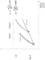
- Figure 2 shows an example of HIFI and TFI graphical representations.
- the inverse of the normalized permeability curve of a membrane versus the specific volume filtered [m3/m2] is represented in two consecutive cycles, cycle 1 and cycle 2.
- the second curve is the line linking the points where impermeability has become irreversible, or in other words, where mechanical cleaning or hydraulic backwash is not able to eliminate fouling of the membrane.
- a chemical cleaning follows two consecutives hydraulic cycles, cycle 1 and cycle 2. In a real filtration system, a chemical cleaning may usually be performed per day, and therefore, every 24 hydraulic cycles of 1 hour.
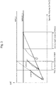
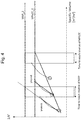
- Figures 3 and 4 show, respectively, further representations of TFI and HIFI during 3 hydraulic cycles.
- a MAP may be set to 60 [LMH/bar] and a MPLCC may be set to 100 [LMH/bar].
- a MAP may be set to 90 [LMH/bar] and a MPLCC may be set to 120 [LMH/bar].
- MAP and MPLCC are usually set points which may be fixed by a user or defined by an artificial intelligence, Al, system, and they may vary depending on a received operational mode. Such values define the action to be performed by the filtration system.
- a “Maximize production” operational mode may be referred to an extreme and non-conservative operational mode, and the membrane may therefore be forced and consider “acceptable” lower permeability levels than in alternative operational modes.
- the driver or objective in such operational mode is to fulfill water demand by improving production, despite possible negative effects in terms of lifespan derived from "forcing" the membrane.
- a "Sustainable Operation" operational mode may be referred to operate a filtration system in a conservative way.
- the drive may be to avoid reaching a certain "non-conservative" permeability value.
- TFI is calculated as the inverse of permeability, based on a lineal regression of both TFI and HIFI
- an extrapolation of TFI to the inverse of MAP and an extrapolation of HIFI to the inverse of MPLCC may be performed and the "time to reach the inverse of MAP/MPLCC" may be forecasted.
- Different levels of fouling may be defined, for example, “high fouling and low fouling", or "high fouling, acceptable fouling and low fouling”.
- a high fouling or high fouling rate may be considered when the inverse of permeability is forecasted to reach the associated inverse of MAP setpoint in less than 80 minutes; in other words, when the extrapolation of TFI is forecasted to reach the MAP limit (or the inverse of MAP) in less than 80 minutes, the system is considered to present a high fouling rate.
- a high fouling or high fouling rate may be considered when an irreversible inverse of permeability is forecasted to reach an associated inverse of MPLCC setpoint in less than 2 days; in other words, when the extrapolation of HIFI is forecasted to reach the MPLCC or inverse of MPLCC limit in less than 2 days.
- a low fouling or low fouling rate may be considered when the permeability is forecasted to reach a MAP setpoint in more than 160 minutes. In some examples, a low fouling or low fouling rate may be considered when irreversible permeability is forecasted to reach a MPLCC in more than 5 days.
- the table below shows some examples of high, acceptable or low fouling rate in a matrix representation: Level Time for TFI to reach inverse of MAP Time for HIFI to reach inverse of MPLCC High fouling rate Time ⁇ 80 minutes Time ⁇ 2 days Acceptable fouling rate 80 ⁇ Time ⁇ 160 minutes 2 ⁇ Time ⁇ 5 days Low fouling rate Time>160 minutes Time>5 days
- the filtration flux may be varied by the processor (102) sending electric commands to valves (not shown) of the filtration system.
- the above actions may be represented as in the table below: High TFI (Time ⁇ 80 min) Acceptable TFI (80 ⁇ Time ⁇ 160 min) Low TFI (Time>160 min) High HIFI (Time ⁇ 2 days) Warning. -5% filtration time / -5% filtration flux Warning. -2% filtration time/ -2% filtration flux Warning. -5% filtration time/ -5% filtration flux Acceptable HIFI (2 ⁇ Time ⁇ 5 days) Warning. -2% filtration time / -2% filtration flux Acceptable. No action performed. Optimize. +2%filtration time/ +2% filtration flux Low HIFI (Time>5 days) Warning. -5% filtration time/ -5% filtration flux Optimize. -5% filtration time/ -5% filtration flux Optimize. -5% filtration time/ -5% filtration flux Optimize. -5% filtration time/ -5% filtration flux
- the setpoints may be modified depending on the system needs. For example, an artificial intelligence, Al, system may determine that if the established setpoints oblige to decrease the filtration flux or time more than twice per day, then the setpoints may be recalibrated.
- Al artificial intelligence
- the operation mode selection triggers a MAP and MPLCC setpoints definition, which in turn, may trigger the definition and/or modification of values of fouling indicators, such as a time to reach the setpoints.
- the setpoints are MAP or MPLCC, and the times for the fouling indicators to reach the setpoints are based on extrapolation and dependent on a received operational mode.
- an energy savings mode may allow to continuously evaluate and compare which action of either modify the filtration flux or modify the filtration time impacts significantly in the energy consumption of the filtration system.
- Figures 3 and 4 represent how the setpoints are varied depending on the operational mode.
- Figures 3 and 4 represent the inverse of permeability, 1/K, inverse of MAP in each figure: MAP_1, MAP_2, and inverse of MPLCC in each figure: MPLCC_1, MPLCC_2.
- the TFI and HIFI regression lines are shown increasing with time or filtered volume "Specific volume”.
- the irreversible fouling after each hydraulic cleaning is represented as an "increasing" curve representing an increasing inverse of permeability.
- Regression lines “y” are obtained for each curve representing the evolution of the inverse of permeability.
- Regression lines “y” are represented departing from each minimum of irreversible fouling indicator after each hydraulic cleaning.
- An extrapolation of the lines “y” is represented in dotted lines, which corresponds to forecasted values, in time, of the regression lines "y” or total fouling index, TFI, and/or of the regression of a hydraulically irreversible fouling index, HIFI.
- Figure 3 represents the filtration system behavior when the operational mode is set to Maximize Production operational mode.
- the setpoints may be MAP_1 and MPLCC_1, corresponding to the inverse of first MAP and inverse of first MPLCC.
- MAP_1 and MPLCC_1 are higher than MAP_2 and MPLCC_2 in figure 4 , where a sustainable operation operational mode is set.
- Figure 4 represents the filtration system behavior when the operational mode is set to Sustainable operational mode, for which setpoints MAP_2 and MPLCC_2, corresponding to the inverse of second MAP and inverse of second MPLCC, are set.
- MAP_2 and MPLCC_2 are lower than MAP_1 and MPLCC_1 of figure 3 .
- the time to reach MAP_1 measured from a point in time where XXX up to a time where the regression line TFI is assumed to reach MAP_1, is greater than the time to Reach MAP_2, and the time to reach MPLCC_1 is greater than the time to reach MPLCC_2.
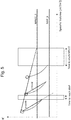
- Figure 5 shows an alternative graphical representation where permeability, K, and MAP and MPLCC are represented, instead of their inverses.
- the regression of TFI and HIFI decrease over time and TFI is calculated as dK/dt instead of d(1/K)/dt.
- Figure 5 shows an example in which, if the objective is to Maximize Production, and MAP is the Minimum acceptable permeability, the MAP to reach may be lower than MAP to operate in a sustainable fashion. For example, in ultrafiltration UF, a possible strategy to enlarge membrane lifetime is to avoid reaching very low permeabilities (usually a limit recommended by the manufacturer); in some operations however, a membrane is "forced" if the objective is to maximize production, in order to respond a certain demand. To visualize that, you have to check Fig 5 , since MAP refers to permeability and not the inverse of permeability.
- the proposed methods and systems may allow the optimization of UF operations.
- Membrane fouling is a constraint when membrane filtration technologies are applied.
- the disclosed methods allow introducing smartness in the development of strategies, which are usually imposed as a fixed set-point, as constants, and are not adapted to the feed changing conditions.
- the disclosed methods allow a smart monitoring of membrane fouling, reversible and irreversible, based on the user or plant needs: maximize production or economic savings or sustainable operation in terms of fouling. These methods allow the adaptation of setpoints to plant needs or feed changing conditions.
- the disclosed methods also perform a set of actions for the optimal management of the fouling control strategies: basic operational conditions, hydraulic cleanings and chemical cleanings, in order to anticipate the operation of the membrane and be able to predict intensive maintenance actions, such as chemical cleanings.
- the disclosed methods also allow the monitoring of high value KPIs such as energy consumption, chemicals consumption or OPEX.
Landscapes
- Chemical & Material Sciences (AREA)
- Chemical Kinetics & Catalysis (AREA)
- Engineering & Computer Science (AREA)
- Water Supply & Treatment (AREA)
- Life Sciences & Earth Sciences (AREA)
- Hydrology & Water Resources (AREA)
- Environmental & Geological Engineering (AREA)
- Organic Chemistry (AREA)
- Separation Using Semi-Permeable Membranes (AREA)
Priority Applications (5)
| Application Number | Priority Date | Filing Date | Title |
|---|---|---|---|
| EP19382783.9A EP3789104A1 (de) | 2019-09-09 | 2019-09-09 | Verfahren und system zur filtration einer flüssigkeit |
| AU2020344936A AU2020344936B2 (en) | 2019-09-09 | 2020-09-08 | Method and system for filtration of a liquid |
| EP20765040.9A EP4028150A1 (de) | 2019-09-09 | 2020-09-08 | Verfahren und system zur filtration einer flüssigkeit |
| PCT/EP2020/074997 WO2021048078A1 (en) | 2019-09-09 | 2020-09-08 | Method and system for filtration of a liquid |
| CN202080077894.8A CN114786794B (zh) | 2019-09-09 | 2020-09-08 | 用于过滤液体的方法和系统 |
Applications Claiming Priority (1)
| Application Number | Priority Date | Filing Date | Title |
|---|---|---|---|
| EP19382783.9A EP3789104A1 (de) | 2019-09-09 | 2019-09-09 | Verfahren und system zur filtration einer flüssigkeit |
Publications (1)
| Publication Number | Publication Date |
|---|---|
| EP3789104A1 true EP3789104A1 (de) | 2021-03-10 |
Family
ID=68069692
Family Applications (2)
| Application Number | Title | Priority Date | Filing Date |
|---|---|---|---|
| EP19382783.9A Withdrawn EP3789104A1 (de) | 2019-09-09 | 2019-09-09 | Verfahren und system zur filtration einer flüssigkeit |
| EP20765040.9A Pending EP4028150A1 (de) | 2019-09-09 | 2020-09-08 | Verfahren und system zur filtration einer flüssigkeit |
Family Applications After (1)
| Application Number | Title | Priority Date | Filing Date |
|---|---|---|---|
| EP20765040.9A Pending EP4028150A1 (de) | 2019-09-09 | 2020-09-08 | Verfahren und system zur filtration einer flüssigkeit |
Country Status (4)
| Country | Link |
|---|---|
| EP (2) | EP3789104A1 (de) |
| CN (1) | CN114786794B (de) |
| AU (1) | AU2020344936B2 (de) |
| WO (1) | WO2021048078A1 (de) |
Families Citing this family (2)
| Publication number | Priority date | Publication date | Assignee | Title |
|---|---|---|---|---|
| CN119018992B (zh) * | 2023-05-23 | 2026-03-10 | 宁波方太厨具有限公司 | 净水设备的水垢处理方法、系统、设备及存储介质 |
| CN117534239B (zh) * | 2023-11-27 | 2024-07-19 | 苏州科索膜技术有限公司 | 一种过滤浓缩系统和方法 |
Citations (4)
| Publication number | Priority date | Publication date | Assignee | Title |
|---|---|---|---|---|
| US20050258098A1 (en) * | 2000-12-13 | 2005-11-24 | Nathalie Vincent | Method for regulating a membrane filtering installation |
| US20110180487A1 (en) * | 2008-08-06 | 2011-07-28 | Veolia Water Solutions & Technologies Support | Optimized Water Treatment Installation and Process |
| WO2011153625A2 (en) * | 2010-06-10 | 2011-12-15 | Ramila Hishantha Peiris | Method for fluorescence-based fouling forecasting and optimization in membrane filtration operations |
| US20160046503A1 (en) * | 2014-08-12 | 2016-02-18 | Water Planet, Inc. | Intelligent fluid filtration management system |
Family Cites Families (1)
| Publication number | Priority date | Publication date | Assignee | Title |
|---|---|---|---|---|
| US7459083B1 (en) * | 2007-05-07 | 2008-12-02 | I. Kruger Inc. | Method for controlling fouling of a membrane filter |
-
2019
- 2019-09-09 EP EP19382783.9A patent/EP3789104A1/de not_active Withdrawn
-
2020
- 2020-09-08 AU AU2020344936A patent/AU2020344936B2/en active Active
- 2020-09-08 CN CN202080077894.8A patent/CN114786794B/zh active Active
- 2020-09-08 EP EP20765040.9A patent/EP4028150A1/de active Pending
- 2020-09-08 WO PCT/EP2020/074997 patent/WO2021048078A1/en not_active Ceased
Patent Citations (4)
| Publication number | Priority date | Publication date | Assignee | Title |
|---|---|---|---|---|
| US20050258098A1 (en) * | 2000-12-13 | 2005-11-24 | Nathalie Vincent | Method for regulating a membrane filtering installation |
| US20110180487A1 (en) * | 2008-08-06 | 2011-07-28 | Veolia Water Solutions & Technologies Support | Optimized Water Treatment Installation and Process |
| WO2011153625A2 (en) * | 2010-06-10 | 2011-12-15 | Ramila Hishantha Peiris | Method for fluorescence-based fouling forecasting and optimization in membrane filtration operations |
| US20160046503A1 (en) * | 2014-08-12 | 2016-02-18 | Water Planet, Inc. | Intelligent fluid filtration management system |
Non-Patent Citations (1)
| Title |
|---|
| HASHIMOTO ET AL: "Raw Water Storage as a Simple Means for Controlling Membrane Fouling Caused by Inorganic Foulants in River Water in a Tropical Region", WATER, vol. 11, no. 8, 1 January 2019 (2019-01-01), CH, pages 1592, XP055670191, ISSN: 2073-4441, DOI: 10.3390/w11081592 * |
Also Published As
| Publication number | Publication date |
|---|---|
| AU2020344936A1 (en) | 2022-03-31 |
| WO2021048078A1 (en) | 2021-03-18 |
| AU2020344936B2 (en) | 2026-02-26 |
| CN114786794A (zh) | 2022-07-22 |
| EP4028150A1 (de) | 2022-07-20 |
| CN114786794B (zh) | 2025-07-22 |
Similar Documents
| Publication | Publication Date | Title |
|---|---|---|
| EP3802432B1 (de) | Prädiktives werkzeug zur überwachung von ro- und nf-membranen | |
| US9790113B2 (en) | Apparatus, system and method for integrated filtration and reverse osmosis desalination | |
| US20050258098A1 (en) | Method for regulating a membrane filtering installation | |
| Kalboussi et al. | Optimal control of physical backwash strategy-towards the enhancement of membrane filtration process performance | |
| EP2731917B1 (de) | Verfahren zur aufrechterhaltung der wasserqualität in einem prozessstrom | |
| JP7437998B2 (ja) | 水処理システム、水処理システムの運転管理支援システム及び水処理システムの運転方法 | |
| Ferrero et al. | Automatic control systems for submerged membrane bioreactors: A state-of-the-art review | |
| EP2560743B1 (de) | Verfahren und system für ein optimiertes membranreinigungsverfahren | |
| US10821404B2 (en) | Control method for a filter system | |
| WO2003059495A1 (en) | Methods for improving filtration performance of hollow fiber membranes | |
| AU2021284984A1 (en) | Apparatus and methods for cleaning reverse osmosis systems | |
| WO2008132186A1 (en) | Supervisory control system and method for membrane cleaning | |
| CN115364536B (zh) | 一种滤池反冲洗系统、滤池系统以及反冲洗方法 | |
| AU2020344936B2 (en) | Method and system for filtration of a liquid | |
| JP6299548B2 (ja) | 濾過システム | |
| KR20260009300A (ko) | 필터 상태를 결정하기 위한 시스템 | |
| JP2006281092A (ja) | 膜濾過設備の制御装置 | |
| Jun et al. | Development of a Dual-Metric Operational Decision Support Model for Full-Scale Submerged Membrane Bioreactors (MBRs) | |
| EA042687B1 (ru) | Инструмент прогнозирования для мониторинга оо- и нф-мембран | |
| KR100930803B1 (ko) | 여과지의 시동방수 재사용 제어방법 | |
| CN120622612A (zh) | 一种海水淡化超滤反渗透装置智能控制系统及方法 |
Legal Events
| Date | Code | Title | Description |
|---|---|---|---|
| PUAI | Public reference made under article 153(3) epc to a published international application that has entered the european phase |
Free format text: ORIGINAL CODE: 0009012 |
|
| STAA | Information on the status of an ep patent application or granted ep patent |
Free format text: STATUS: THE APPLICATION HAS BEEN PUBLISHED |
|
| AK | Designated contracting states |
Kind code of ref document: A1 Designated state(s): AL AT BE BG CH CY CZ DE DK EE ES FI FR GB GR HR HU IE IS IT LI LT LU LV MC MK MT NL NO PL PT RO RS SE SI SK SM TR |
|
| AX | Request for extension of the european patent |
Extension state: BA ME |
|
| STAA | Information on the status of an ep patent application or granted ep patent |
Free format text: STATUS: THE APPLICATION IS DEEMED TO BE WITHDRAWN |
|
| 18D | Application deemed to be withdrawn |
Effective date: 20210911 |