EP3789276A1 - Beweglich zu öffnende aktive spoileranordnung - Google Patents
Beweglich zu öffnende aktive spoileranordnung Download PDFInfo
- Publication number
- EP3789276A1 EP3789276A1 EP19207875.6A EP19207875A EP3789276A1 EP 3789276 A1 EP3789276 A1 EP 3789276A1 EP 19207875 A EP19207875 A EP 19207875A EP 3789276 A1 EP3789276 A1 EP 3789276A1
- Authority
- EP
- European Patent Office
- Prior art keywords
- spoiler
- connecting rod
- active
- movable
- vehicle
- Prior art date
- Legal status (The legal status is an assumption and is not a legal conclusion. Google has not performed a legal analysis and makes no representation as to the accuracy of the status listed.)
- Withdrawn
Links
Images
Classifications
-
- B—PERFORMING OPERATIONS; TRANSPORTING
- B62—LAND VEHICLES FOR TRAVELLING OTHERWISE THAN ON RAILS
- B62D—MOTOR VEHICLES; TRAILERS
- B62D35/00—Vehicle bodies characterised by streamlining
- B62D35/007—Rear spoilers
-
- B—PERFORMING OPERATIONS; TRANSPORTING
- B62—LAND VEHICLES FOR TRAVELLING OTHERWISE THAN ON RAILS
- B62D—MOTOR VEHICLES; TRAILERS
- B62D37/00—Stabilising vehicle bodies without controlling suspension arrangements
- B62D37/02—Stabilising vehicle bodies without controlling suspension arrangements by aerodynamic means
-
- Y—GENERAL TAGGING OF NEW TECHNOLOGICAL DEVELOPMENTS; GENERAL TAGGING OF CROSS-SECTIONAL TECHNOLOGIES SPANNING OVER SEVERAL SECTIONS OF THE IPC; TECHNICAL SUBJECTS COVERED BY FORMER USPC CROSS-REFERENCE ART COLLECTIONS [XRACs] AND DIGESTS
- Y02—TECHNOLOGIES OR APPLICATIONS FOR MITIGATION OR ADAPTATION AGAINST CLIMATE CHANGE
- Y02T—CLIMATE CHANGE MITIGATION TECHNOLOGIES RELATED TO TRANSPORTATION
- Y02T10/00—Road transport of goods or passengers
- Y02T10/80—Technologies aiming to reduce greenhouse gasses emissions common to all road transportation technologies
- Y02T10/82—Elements for improving aerodynamics
Definitions
- the present invention relates to the field of active spoilers, and specifically, to a movably opened active spoiler assembly.
- An active spoiler is an auxiliary device that is added to adapt to the impact of aerodynamic down force and lift force due to a change of a vehicle speed in a running process for the purpose of safe driving performance of the vehicle.
- An objective of the present invention is to provide an active spoiler assembly that can be movably opened, so as to resolve the problems of the prior art for lack of an active spoiler device that can adapt to a change of a vehicle speed so as to reduce wind resistance of the entire vehicle and increase aerodynamic downforce of the vehicle.
- the active spoiler assembly is assembled at the rear of a vehicle and includes: a spoiler body fixed relative to a vehicle body, wherein an accommodation space is formed inside the spoiler body, and an opening is formed at the rear of the spoiler body; an electrical motor fixed on the vehicle body, a motor spindle driven by the electrical motor, and a connecting rod mechanism being connected with and driven by the motor spindle; and a movable spoiler being connected with the connecting rod mechanism, wherein the movable spoiler performs translational movement along the longitudinal direction of the vehicle body under an action of the connecting rod mechanism, and the movable spoiler extends out and retracts back through the opening at the rear of the spoiler body such that the active spoiler assembly can be movably opened.
- the active spoiler assembly further comprises a first fixed support fixed inside the spoiler body and the connecting rod mechanism includes a first connecting rod and a second connecting rod connecting the movable spoiler with the first fixed support.
- an end of the first connecting rod is connected to the first fixed support by means of the motor spindle, and the other end of the first connecting rod is connected to the second connecting rod by means of a first rotating shaft.
- the active spoiler assembly further comprises a second fixed support fixed inside the spoiler body and the connecting rod mechanism further includes a third connecting rod and a fourth connecting rod connecting the movable spoiler with the second fixed support, the third connecting rod is connected to the second connecting rod by means of a second rotating shaft, the other end of the second rotating shaft is fastened to the movable spoiler, and the fourth connecting rod is connected to the second fixed support by means of a third rotating shaft.
- the third connecting rod is connected with the fourth connecting rod by an overlap joint by means of a sliding axle fixed on the third connecting rod, and the fourth connecting rod is provided with a waist shape slot configured such that the sliding axle can slide therein.
- the part of the movable spoiler that extends out and retracts back through the opening at the rear of the spoiler body has a flare-shaped structure or a tubular-shaped structure.
- the spoiler body is provided with a streamlined external contour.
- the upper and lower sides of the movable spoiler are respectively pressed tight by pressure plates, to prevent the movable spoiler from shifting in a vertical direction.
- the pressure plates are fastened inside the spoiler body by welding or a connection element.
- two active spoiler assemblies share the same electrical motor.
- the active spoiler assembly can adapt to a vehicle speed change, effectively reduce the safe driving risk caused by an excessively high speed and thus an excessively large lifting force of the vehicle, and reduce energy loss to improve battery life, to realize high speed safe driving and green environmental protection, energy saving and emission reduction functions.
- the present invention provides a movably opened active spoiler assembly that can adapt to a vehicle speed change, reduce air drag of the entire vehicle, and increase aerodynamic downforce of the vehicle.
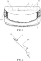
- FIG. 1 and FIG. 2 are schematic status diagrams of a movably opened active spoiler assembly 100 assembled at the rear of a vehicle 200 according to a preferred embodiment of the present invention.
- the vehicle 200 is provided with two active spoiler assemblies 100, which share a same electrical motor 2 and a same motor spindle 3.
- a movable spoiler 10 of the active spoiler assembly 100 performs outspread and retracting motions at the rear of the vehicle 200 when the vehicle 200 is running, to adapt to air downforce caused by a vehicle speed change in the running process.
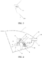
- the active spoiler assembly 100 includes: a spoiler body 1, the electrical motor 2, the motor spindle 3, a connecting rod mechanism including a first connecting rod 4, a second connecting rod 5, a third connecting rod 6, and a fourth connecting rod 7, a first fixed support 8, a second fixed support 9, and the movable spoiler 10.
- the spoiler body 1 is fixed relative to a vehicle body. An accommodation space is formed inside the spoiler body 1 for mounting other components. An opening 11 is formed at the rear of the spoiler body 1 to enable the movable spoiler 10 to perform outspread and retracting motions through the opening.
- the electrical motor 2 is fixed on the vehicle body (as shown in FIG. 1 ), and is driven connected to the motor spindle 3. The motor spindle 3 is further connected to the connecting rod mechanism to drive the connecting rod mechanism to move.
- the first fixed support 8 and the second fixed support 9 are respectively fixed inside the spoiler body 1.
- the movable spoiler 10 is respectively connected to the first fixed support 8 and the second fixed support 9 via the connecting rod mechanism.
- the movable spoiler 10 can perform translational movement along the longitudinal direction of the vehicle body under an action of the connecting rod mechanism, and stretches out and retracts from the opening 11 at the rear of the spoiler body 1, to adapt to air downforce caused by a vehicle speed change in a running process, thereby performing an active spoiler function.
- the movable spoiler 10 is connected to the first fixed support 8 via the first connecting rod 4 and the second connecting rod 5.
- An end of the first connecting rod 4 is connected to the first fixed support 8 via the motor spindle 3, the other end is connected to the second connecting rod 5 by using a first rotating shaft 12.
- the movable spoiler 10 is connected to the second fixed support 9 via the third connecting rod 6 and the fourth connecting rod 7.
- An end of the third connecting rod 6 is connected to the second connecting rod 5 by using a second rotating shaft 13.
- the other end of the second rotating shaft 13 is fastened to the movable spoiler 10.
- the fourth connecting rod 7 is connected to the second fixed support 9 by using a third rotating shaft (not shown in the figures).
- the third connecting rod 6 is connected with the fourth connecting rod 7 by an overlap joint by means of a sliding axle 14 fixed on the third connecting rod 6.
- the fourth connecting rod 7 is further provided with a waist shape slot 15 configured such that the sliding axle 14 can slide therein.
- the part of the movable spoiler 10 that extends out and retracts back from the opening 11 at the rear of the spoiler body 1 has a flare-shaped structure 16.
- the external contour of the flare-shaped structure 16 can effectively increase the aerodynamic downforce of the vehicle in a high-speed running status.
- the extending part of the movable spoiler 10 may alternatively be any proper shaped structure designed according to the rear shape of the vehicle, for example, a tubular-shaped structure, and is not limited to a flare shape.
- the spoiler body has a streamlined external contour, to reduce wind resistance to the most extent, thereby increasing the battery endurance mileage.
- the upper and lower sides of the movable spoiler 10 are respectively pressed tight by pressure plates, to prevent the movable spoiler 10 from shifting in a vertical direction.
- the pressure plates may be fastened inside the spoiler body 1 by welding or a connection element.
- the working principles of the active spoiler assembly 100 are as follows: In a vehicle running process, after a vehicle speed sensor or a pressure sensor sends a signal to a vehicle computer, the vehicle computer outputs the signal to activate the electrical motor 2 to rotate.
- the motor 2 drives the motor spindle 3 to rotate, and then drives the first connecting rod 4 to rotate.
- the second connecting rod 5 correspondingly rotates, and then drives the active spoiler 10 to slide along the horizontal direction.
- the third connecting rod 6 and the fourth connecting rod 7 move with the motion of the active spoiler 10.
Landscapes
- Engineering & Computer Science (AREA)
- Chemical & Material Sciences (AREA)
- Combustion & Propulsion (AREA)
- Transportation (AREA)
- Mechanical Engineering (AREA)
- Physics & Mathematics (AREA)
- Fluid Mechanics (AREA)
- Arrangement Or Mounting Of Propulsion Units For Vehicles (AREA)
Applications Claiming Priority (2)
| Application Number | Priority Date | Filing Date | Title |
|---|---|---|---|
| CN201921490853.2U CN211032788U (zh) | 2019-09-09 | 2019-09-09 | 一种可移动开启的主动扰流板总成 |
| CN201910849262.8A CN110450864B (zh) | 2019-09-09 | 2019-09-09 | 一种可移动开启的主动扰流板总成 |
Publications (1)
| Publication Number | Publication Date |
|---|---|
| EP3789276A1 true EP3789276A1 (de) | 2021-03-10 |
Family
ID=68501362
Family Applications (1)
| Application Number | Title | Priority Date | Filing Date |
|---|---|---|---|
| EP19207875.6A Withdrawn EP3789276A1 (de) | 2019-09-09 | 2019-11-08 | Beweglich zu öffnende aktive spoileranordnung |
Country Status (1)
| Country | Link |
|---|---|
| EP (1) | EP3789276A1 (de) |
Cited By (2)
| Publication number | Priority date | Publication date | Assignee | Title |
|---|---|---|---|---|
| US20230159114A1 (en) * | 2021-11-23 | 2023-05-25 | Honda Motor Co., Ltd. | Deployable Active D-Pillar Spoiler for Vehicles |
| US20240116581A1 (en) * | 2022-10-11 | 2024-04-11 | Dr. Ing. H.C. F. Porsche Aktiengesellschaft | Motor vehicle with a rear spoiler |
Citations (5)
| Publication number | Priority date | Publication date | Assignee | Title |
|---|---|---|---|---|
| DE2851639A1 (de) * | 1978-11-29 | 1980-06-04 | B & B Beteiligung | Vorrichtung zur leitung der windstroemung an fahrzeugen |
| US4738479A (en) * | 1985-11-12 | 1988-04-19 | Fiat Auto S.P.A. | Mobile car stabilizer actuating device |
| EP2007615A1 (de) * | 2006-02-27 | 2008-12-31 | HS Genion GmbH | Luftleiteinrichtung für ein fahrzeug |
| EP2716529A2 (de) * | 2012-10-02 | 2014-04-09 | HS Genion GmbH | Luftleiteinrichtung mit Kinematik-Bremseinrichtung |
| EP2733054A2 (de) * | 2012-11-19 | 2014-05-21 | SUSPA GmbH | Vorrichtung zur Verlagerung eines Gegenstands und Kraftfahrzeug mit einer derartigen Vorrichtung |
-
2019
- 2019-11-08 EP EP19207875.6A patent/EP3789276A1/de not_active Withdrawn
Patent Citations (5)
| Publication number | Priority date | Publication date | Assignee | Title |
|---|---|---|---|---|
| DE2851639A1 (de) * | 1978-11-29 | 1980-06-04 | B & B Beteiligung | Vorrichtung zur leitung der windstroemung an fahrzeugen |
| US4738479A (en) * | 1985-11-12 | 1988-04-19 | Fiat Auto S.P.A. | Mobile car stabilizer actuating device |
| EP2007615A1 (de) * | 2006-02-27 | 2008-12-31 | HS Genion GmbH | Luftleiteinrichtung für ein fahrzeug |
| EP2716529A2 (de) * | 2012-10-02 | 2014-04-09 | HS Genion GmbH | Luftleiteinrichtung mit Kinematik-Bremseinrichtung |
| EP2733054A2 (de) * | 2012-11-19 | 2014-05-21 | SUSPA GmbH | Vorrichtung zur Verlagerung eines Gegenstands und Kraftfahrzeug mit einer derartigen Vorrichtung |
Cited By (3)
| Publication number | Priority date | Publication date | Assignee | Title |
|---|---|---|---|---|
| US20230159114A1 (en) * | 2021-11-23 | 2023-05-25 | Honda Motor Co., Ltd. | Deployable Active D-Pillar Spoiler for Vehicles |
| US11939005B2 (en) * | 2021-11-23 | 2024-03-26 | Honda Motor Co., Ltd. | Deployable active D-pillar spoiler for vehicles |
| US20240116581A1 (en) * | 2022-10-11 | 2024-04-11 | Dr. Ing. H.C. F. Porsche Aktiengesellschaft | Motor vehicle with a rear spoiler |
Similar Documents
| Publication | Publication Date | Title |
|---|---|---|
| CN110450864B (zh) | 一种可移动开启的主动扰流板总成 | |
| CN211032788U (zh) | 一种可移动开启的主动扰流板总成 | |
| CN203651491U (zh) | 一种电力汽车用受电弓 | |
| CN220410908U (zh) | 一种可变形陆空两栖机器人 | |
| CN106515460A (zh) | 一种受电弓充电系统、受电弓防护罩及车辆 | |
| CN110254240B (zh) | 一种电动车能量收集转换装置 | |
| CN211032792U (zh) | 一种后扰流板总成 | |
| CN109353489B (zh) | 一种无人机多功能襟翼结构 | |
| CN214823697U (zh) | 一种汽车电动升降折叠尾翼 | |
| CN115214806B (zh) | 一种智能可调通用导流罩 | |
| CN219904721U (zh) | 襟翼收放装置和飞行器 | |
| CN210490774U (zh) | 一种太阳能电池板伸缩机构 | |
| CN219030754U (zh) | 穿梭车 | |
| CN219107224U (zh) | 一种驱动机构、气坝装置及车辆 | |
| CN202156332U (zh) | 电动三轮车自动卸货升降装置 | |
| CN105438783A (zh) | 转向机中的挡箱机构 | |
| EP3792163B1 (de) | Drehbarer aktiver diffusor für fahrzeug | |
| CN206217644U (zh) | 受电弓充电系统、受电弓防护罩及车辆 | |
| CN116374161A (zh) | 襟翼收放装置和飞行器 | |
| CN209669739U (zh) | 交通锥收放系统用预储能机构 | |
| CN219979526U (zh) | 一种石墨舟片卡点顶升组件 | |
| CN210101804U (zh) | 一种可旋转开启的主动扰流板结构 | |
| CN107322643A (zh) | 一种工业机器人用主动式防缠绕车轴 | |
| CN223658438U (zh) | 一种无人机伸缩机翼 | |
| CN222310761U (zh) | 车辆 |
Legal Events
| Date | Code | Title | Description |
|---|---|---|---|
| PUAI | Public reference made under article 153(3) epc to a published international application that has entered the european phase |
Free format text: ORIGINAL CODE: 0009012 |
|
| STAA | Information on the status of an ep patent application or granted ep patent |
Free format text: STATUS: THE APPLICATION HAS BEEN PUBLISHED |
|
| AK | Designated contracting states |
Kind code of ref document: A1 Designated state(s): AL AT BE BG CH CY CZ DE DK EE ES FI FR GB GR HR HU IE IS IT LI LT LU LV MC MK MT NL NO PL PT RO RS SE SI SK SM TR |
|
| AX | Request for extension of the european patent |
Extension state: BA ME |
|
| STAA | Information on the status of an ep patent application or granted ep patent |
Free format text: STATUS: THE APPLICATION IS DEEMED TO BE WITHDRAWN |
|
| 18D | Application deemed to be withdrawn |
Effective date: 20210911 |