EP3789344A1 - Modulierbares system zur erzeugung von endogas mit einstellbarem kohlenmonoxidgehalt - Google Patents
Modulierbares system zur erzeugung von endogas mit einstellbarem kohlenmonoxidgehalt Download PDFInfo
- Publication number
- EP3789344A1 EP3789344A1 EP20187368.4A EP20187368A EP3789344A1 EP 3789344 A1 EP3789344 A1 EP 3789344A1 EP 20187368 A EP20187368 A EP 20187368A EP 3789344 A1 EP3789344 A1 EP 3789344A1
- Authority
- EP
- European Patent Office
- Prior art keywords
- endogas
- catalytic
- generator
- tubes
- air
- Prior art date
- Legal status (The legal status is an assumption and is not a legal conclusion. Google has not performed a legal analysis and makes no representation as to the accuracy of the status listed.)
- Granted
Links
Images
Classifications
-
- C—CHEMISTRY; METALLURGY
- C01—INORGANIC CHEMISTRY
- C01B—NON-METALLIC ELEMENTS; COMPOUNDS THEREOF; METALLOIDS OR COMPOUNDS THEREOF NOT COVERED BY SUBCLASS C01C
- C01B3/00—Hydrogen; Gaseous mixtures containing hydrogen; Separation of hydrogen from mixtures containing it; Purification of hydrogen; Reversible storage of hydrogen
- C01B3/02—Production of hydrogen; Production of gaseous mixtures containing hydrogen
- C01B3/32—Production of hydrogen; Production of gaseous mixtures containing hydrogen by reaction of gaseous or liquid organic compounds with gasifying agents, e.g. water, carbon dioxide or air
- C01B3/34—Production of hydrogen; Production of gaseous mixtures containing hydrogen by reaction of gaseous or liquid organic compounds with gasifying agents, e.g. water, carbon dioxide or air by reaction of hydrocarbons with gasifying agents
- C01B3/38—Production of hydrogen; Production of gaseous mixtures containing hydrogen by reaction of gaseous or liquid organic compounds with gasifying agents, e.g. water, carbon dioxide or air by reaction of hydrocarbons with gasifying agents using catalysts
- C01B3/40—Production of hydrogen; Production of gaseous mixtures containing hydrogen by reaction of gaseous or liquid organic compounds with gasifying agents, e.g. water, carbon dioxide or air by reaction of hydrocarbons with gasifying agents using catalysts characterised by the catalyst
-
- B—PERFORMING OPERATIONS; TRANSPORTING
- B01—PHYSICAL OR CHEMICAL PROCESSES OR APPARATUS IN GENERAL
- B01J—CHEMICAL OR PHYSICAL PROCESSES, e.g. CATALYSIS OR COLLOID CHEMISTRY; THEIR RELEVANT APPARATUS
- B01J23/00—Catalysts comprising metals or metal oxides or hydroxides, not provided for in group B01J21/00
- B01J23/38—Catalysts comprising metals or metal oxides or hydroxides, not provided for in group B01J21/00 of noble metals
- B01J23/40—Catalysts comprising metals or metal oxides or hydroxides, not provided for in group B01J21/00 of noble metals of the platinum group metals
-
- B—PERFORMING OPERATIONS; TRANSPORTING
- B01—PHYSICAL OR CHEMICAL PROCESSES OR APPARATUS IN GENERAL
- B01J—CHEMICAL OR PHYSICAL PROCESSES, e.g. CATALYSIS OR COLLOID CHEMISTRY; THEIR RELEVANT APPARATUS
- B01J23/00—Catalysts comprising metals or metal oxides or hydroxides, not provided for in group B01J21/00
- B01J23/38—Catalysts comprising metals or metal oxides or hydroxides, not provided for in group B01J21/00 of noble metals
- B01J23/54—Catalysts comprising metals or metal oxides or hydroxides, not provided for in group B01J21/00 of noble metals combined with metals, oxides or hydroxides provided for in groups B01J23/02 - B01J23/36
- B01J23/56—Platinum group metals
- B01J23/64—Platinum group metals with arsenic, antimony, bismuth, vanadium, niobium, tantalum, polonium, chromium, molybdenum, tungsten, manganese, technetium or rhenium
- B01J23/656—Manganese, technetium or rhenium
- B01J23/6567—Rhenium
-
- B—PERFORMING OPERATIONS; TRANSPORTING
- B01—PHYSICAL OR CHEMICAL PROCESSES OR APPARATUS IN GENERAL
- B01J—CHEMICAL OR PHYSICAL PROCESSES, e.g. CATALYSIS OR COLLOID CHEMISTRY; THEIR RELEVANT APPARATUS
- B01J23/00—Catalysts comprising metals or metal oxides or hydroxides, not provided for in group B01J21/00
- B01J23/90—Regeneration or reactivation
- B01J23/96—Regeneration or reactivation of catalysts comprising metals, oxides or hydroxides of the noble metals
-
- B—PERFORMING OPERATIONS; TRANSPORTING
- B01—PHYSICAL OR CHEMICAL PROCESSES OR APPARATUS IN GENERAL
- B01J—CHEMICAL OR PHYSICAL PROCESSES, e.g. CATALYSIS OR COLLOID CHEMISTRY; THEIR RELEVANT APPARATUS
- B01J37/00—Processes, in general, for preparing catalysts; Processes, in general, for activation of catalysts
- B01J37/02—Impregnation, coating or precipitation
- B01J37/0215—Coating
-
- B—PERFORMING OPERATIONS; TRANSPORTING
- B01—PHYSICAL OR CHEMICAL PROCESSES OR APPARATUS IN GENERAL
- B01J—CHEMICAL OR PHYSICAL PROCESSES, e.g. CATALYSIS OR COLLOID CHEMISTRY; THEIR RELEVANT APPARATUS
- B01J38/00—Regeneration or reactivation of catalysts, in general
- B01J38/04—Gas or vapour treating; Treating by using liquids vaporisable upon contacting spent catalyst
-
- Y—GENERAL TAGGING OF NEW TECHNOLOGICAL DEVELOPMENTS; GENERAL TAGGING OF CROSS-SECTIONAL TECHNOLOGIES SPANNING OVER SEVERAL SECTIONS OF THE IPC; TECHNICAL SUBJECTS COVERED BY FORMER USPC CROSS-REFERENCE ART COLLECTIONS [XRACs] AND DIGESTS
- Y02—TECHNOLOGIES OR APPLICATIONS FOR MITIGATION OR ADAPTATION AGAINST CLIMATE CHANGE
- Y02P—CLIMATE CHANGE MITIGATION TECHNOLOGIES IN THE PRODUCTION OR PROCESSING OF GOODS
- Y02P20/00—Technologies relating to chemical industry
- Y02P20/50—Improvements relating to the production of bulk chemicals
- Y02P20/52—Improvements relating to the production of bulk chemicals using catalysts, e.g. selective catalysts
-
- Y—GENERAL TAGGING OF NEW TECHNOLOGICAL DEVELOPMENTS; GENERAL TAGGING OF CROSS-SECTIONAL TECHNOLOGIES SPANNING OVER SEVERAL SECTIONS OF THE IPC; TECHNICAL SUBJECTS COVERED BY FORMER USPC CROSS-REFERENCE ART COLLECTIONS [XRACs] AND DIGESTS
- Y02—TECHNOLOGIES OR APPLICATIONS FOR MITIGATION OR ADAPTATION AGAINST CLIMATE CHANGE
- Y02P—CLIMATE CHANGE MITIGATION TECHNOLOGIES IN THE PRODUCTION OR PROCESSING OF GOODS
- Y02P20/00—Technologies relating to chemical industry
- Y02P20/50—Improvements relating to the production of bulk chemicals
- Y02P20/584—Recycling of catalysts
Definitions
- the present invention relates to a modulable plant for the production of controlled atmosphere of endogas (i.e. endothermic gas), with a percentage of carbon monoxide (CO) and/or hydrogen (H 2 ) that can be set by the user, for feeding a plurality of furnaces for heat treatment of metals and their alloys.
- endogas i.e. endothermic gas
- CO carbon monoxide
- H 2 hydrogen
- the present invention relates to such a plant capable of producing endogas using a catalyst with a base of noble metal oxides and a binary mixture with a base of air and methane (or another hydrocarbon), said endogas produced having a constant volumetric composition also at feed rates reduced up to 90% with respect to the nominal flow rate of said plant.
- the present invention relates to a plant as defined above in which the percentage of carbon monoxide (CO) and/or hydrogen (H 2 ) contained in the endogas can be set by the user according to requirements.
- CO carbon monoxide
- H 2 hydrogen
- said modulable plant can produce endogas at percentages of CO or H 2 that are even increased with respect to the endogas generators known in the art, when the feed to the catalytic reactor is a ternary mixture based on air, methane and carbon dioxide (CO 2 ).
- this modulable system can perform the regeneration of the catalyst of the reaction retorts that are not in function during normal operation of the plant, for example when there is a lower demand for endogas flow to be produced.
- Endogas is a gas mixture, also called “endothermic mixture” or “controlled atmosphere”, rich in CO, H 2 and N 2 , as well as containing to a lesser extent H 2 O and CO 2 , which is used both as a protective atmosphere in heat and/or surface treatments of metals (with respect to oxidation), and as a mixture able to confer certain mechanical properties to the metal undergoing treatment, for example in the surface carburization of steel parts intended for mechanical members that must combine fatigue resistance with surface hardness and wear resistance.
- the above optimal composition is currently the result of a reaction conducted using specific nickel-based catalysts (i.e. nickel hexahydrate oxides, on an alumina substrate), with molar ratios between air and natural gas comprised between 2.25/1 and 2.75/1, and at a temperature comprised between 1000 and 1100°C, generally around 1050°C.
- specific nickel-based catalysts i.e. nickel hexahydrate oxides, on an alumina substrate
- Said endogas is produced in special and appropriate plants called “endogas generators”, formed by a heating chamber that supplies heat to a catalytic reactor, placed inside it.
- Said reactor is formed by one or two cylindrical “retorts”, in the form of a simple tube or U-tube, containing the catalyst, followed by a heat exchanger, usually gas/water, to rapidly cool the reaction products so as to avoid that the reaction proceeds further forming CO 2 in high quantities to the detriment of CO. From said exchanger the endogas exits at a temperature generally lower than 150°C, preferably lower than 100°C.
- the spatial speed of the catalyst used which defines the quantity of gas that passes per unit of time (Nm 3 /h) in relation to the catalyst volume (litres), and is inversely proportional to the dwell time of the gas in the catalyst. This parameter allows calculation of the catalyst volume necessary to have the maximum conversion efficiency at the working temperature of the catalyst on which the obtaining of the abovementioned optimal composition depends.
- the activity of nickel-based catalysts is not very high, in particular the selectivity towards H 2 and CO is below 100% and the spatial speed (defined as the quantity of endogas produced with optimal composition in the unit of time by the catalyst volume unit) is less than 4000 h-1, i.e. less than 4 Nm 3 /h of endogas produced per litre of catalyst.
- Said catalyst is presented in the form of balls and/or cubes with an approximate diameter of 18 mm and a side of 18-25 mm, normally with a diameter or side that does not exceed 40 mm in order to reduce pressure drops and have a sufficient active surface.
- the diameter of the reactor is sized accordingly. This diameter is generally larger than 100 mm in current endogas generators, which adopt one or two reaction “retorts", to limit the height development of the combustion chamber and provide a sufficient catalytic bed (catalyst volume).
- Endogas generators with three retorts are also commercially available, but the diameter of each tube is in any case greater than 100 mm, again in order to limit the height dimensions of the heating chamber and of the head of the catalytic bed which, if excessive, would lead to counter-pressures that would also prevent the flow of reaction gases in the expected flow rates.
- the flow rate is reduced without altering the optimal composition of the endogas by providing two by-pass lines, one on the air/methane mixture feed and the other on the endogas produced.
- this type of system provides for the decrease in the flow rate by a maximum of 30% because further decreases excessively modify the speed and composition, resulting in a plant that is not very modulable in terms of productivity.
- a further reduction in flow rate for example around 50%, is achieved by some known plants, with one or two retorts, using a variable speed pump or making one retort work instead of two.
- reductions below 50% of the nominal flow rate are not currently envisaged without affecting the composition.
- composition of the endogas affects the performances of metallurgical treatments, it is important to maintain the abovementioned optimal composition throughout the production of the same, even for flow rates much lower than the nominal one of the plant.
- a modulable system has been provided in the art formed by several generators mounted in parallel, each with its own retort and appropriate feed system, where a centralised automatic control system manages the activation, deactivation or partialization of the pumps in such a way that at the demand for a high flow rate several generators are activated, while at the demand for a lower flow rate several generators are deactivated and/or the pump speed of one or more generators is reduced to cover the widest possible range of flow rates.
- Patent application GB 2 222 096 describes a combined system of steam reforming and partial oxidation which foresees a plurality of tubes in the form of a tube bundle, containing a suitable catalyst, where said tubes are fed by a single flow in input to said tube bundle having a pressure higher than 50 barG, without the possibility of individually excluding one or more tubes forming the tube bundle.
- Patent application EP 2851339 A1 in the name of the Applicant describes an endogas generator that can be modulated in the flow rate produced and fed with a binary mixture of air + methane, which allows an always constant composition to be obtained, even at low flow rates.
- the CO content reaches 20-22.5% (volumetric composition) and the H 2 content reaches 40-45% (volumetric composition).
- Publication EP 2 851 339 A1 makes known a system for the generation of endogas, in which all catalytic tubes are fed with an air/methane mixture for the formation of endogas with a CO content of 20-22.5%.
- said types of enriched atmosphere are currently produced directly in the hot chamber of the furnaces from nitrogen and methanol, without the use of any endogas generator.
- a mixture of methyl alcohol (pure or denatured) diluted with nitrogen is fed into the hot chamber of the furnace for the treatment of metals so as to cause the pyrolysis of the methanol which allows a volumetric composition to be had of more than 20% CO, maintaining an H 2 /CO volumetric ratio indicatively equal to 2 (two).
- known endogas generators preferably use methane and not other more branched hydrocarbons (ethane, propane, etc.) in that the ratio between the H and C atoms of said gaseous hydrocarbons would result in an endogas with an H 2 /CO volumetric ratio lower than 1.6.
- This is disadvantageous in that a reduced H 2 concentration due to the reduced H 2 /CO ratio would nullify any increase in CO, since H 2 is a promoter of cementation.
- the object of the present invention is to overcome, at least in part, the disadvantages of the prior art by providing an endogas generator capable of modulating in an improved manner the flow rate of endogas produced, ensuring at the same time the optimal composition of the endogas at any flow rate produced, also in the case wherein it is much lower than the nominal flow rate of the generator (flow rate of endogas produced).
- a further object of the present invention is to be able to produce endogas having the percentage of CO increased up to 26% in volume and up to 52% in volume in the case of H 2 , maintaining at the same time an H 2 /CO volumetric ratio indicatively equal to 2 and in any case higher than 1.6.
- a further object is to provide such a generator that is inexpensive, easy to manage and which, in the case of catalyst fouling, can be regenerated, also partially, during operation without negatively affecting the optimal composition of endogas due to the decrease in flow rate.
- a subject of the present invention relates to a plant with an endogas generator to produce a flow Q of an endothermic gas mixture (endogas), optionally containing high percentages of CO higher than 20% (by volume) also up to 26%, starting from a reaction gas mixture comprising air + methane (or another hydrocarbon, e.g. ethane, propane, etc.).
- Said flow Q of endogas is intended to be used for feeding one or more furnaces for heat treatment of metals and their alloys.
- Natural gas here is understood to mean in particular a gaseous mixture produced by the anaerobic decomposition of organic material, composed mainly of methane (typically >90% volume), also containing heavier gaseous hydrocarbons such as ethane (typically ⁇ 5% volume), propane (typically ⁇ 2% volume) and others more branched in smaller percentages.
- methane typically >90% volume
- heavier gaseous hydrocarbons such as ethane (typically ⁇ 5% volume), propane (typically ⁇ 2% volume) and others more branched in smaller percentages.
- gases other than hydrocarbons are always present, for example carbon dioxide (CO 2 ), nitrogen, oxygen (in traces), noble gases and hydrogen sulphide (H 2 S).
- the present endogas generator is suitable for the production of approximately 100 Nm 3 /h but can be dimensioned for a production comprised between 50-200 Nm 3 /h.
- the present endogas generator comprises a catalytic reactor which is contained in the interior of a heated chamber and is composed of at least three catalytic tubes placed in parallel in the form of a tube bundle, where each of said catalytic tubes contains, at least in one tube section, a catalyst based on noble metal oxides by partial oxidation of an air-methane (or other hydrocarbon) or air-methane-carbon dioxide (or other hydrocarbon) mixture.
- the heated chamber is a chamber for the heating of the reactor in that placed externally around it and which supplies heat to the catalytic reactor by means of burners.
- the catalyst used in the catalytic tubes is a catalyst for partial oxidation of air-methane (or another hydrocarbon) or air-methane-carbon dioxide (or another hydrocarbon) mixtures, and is based on noble metal oxides with a spatial speed greater than 4000 h-1.
- each of said catalytic tubes is less than 100.0 mm and can be advantageously comprised between 50.0 and 99.9 mm.
- Each catalytic tube is then in fluid communication with a respective feed tube, external to said heated chamber, and is provided for the purpose of feeding each catalytic tube with a respective flow Qi (volume flow rate), which is the optimum feed flow rate for having a speed on the catalyst such as to make it as efficient as possible.
- Qi volume flow rate
- Each feed tube is then equipped with respective selectable means of regulation which are designed to exclude, if required, the respective feed flow Qi so as to be able to reduce the overall feed flow Qi to the catalytic tubes and thus the volume flow rate Q of endogas leaving the reactor, with respect to a pre-set nominal overall flow rate (Qn) of endogas corresponding to the functioning of all the catalytic tubes.
- the abovementioned selectable means of regulation can be advantageously a shut-off valve, preferably three-way, in particular of the automatic type.
- Said endogas generator also comprises at least one gas/air exchanger for cooling of the endogas leaving said catalytic reactor.
- the cooling of the endogas produced that comes out of the catalytic tubes is advantageously rapid cooling, and preferably such as to quickly bring the temperature of the endogas below 100°C in order to avoid that the reaction proceeds further forming CO 2 in high quantities.
- said gas/air exchanger provides at least one cooling tube in fluid communication with at least one of said catalytic tubes, preferably with all the at least three catalytic tubes, even if in general, even more advantageously, a plurality of cooling tubes are provided in a number generally equal to the number of catalytic tubes, where each cooling tube is in fluid communication only with a respective catalytic tube.
- the peculiarity of the endogas generator according to the invention is to provide an automated mixing and control system, upstream of the catalytic reactor, which comprises at least two mixing units which are independent one of the other, while controlling both selectable means of regulation. In this way it is possible to regulate/control independently
- CO-enriched endogas can be produced in the same generator.
- the mixing system in the present endogas generator is designed to produce, fed to said catalytic reactor, mixtures of
- the selectable means of regulation e.g. the shut-off valves
- the selectable means of regulation have therefore the function of individually excluding one or more of the tubes for feeding to the catalytic tubes so as to obtain an overall feed flow Q that is lower with respect to said nominal flow Qn of the generator, said overall flow Q being, in practice, the sum of the single flows Qi in input to each feed tube of each catalytic tube, Qi being possibly a binary air+methane mixture, a ternary air+methane+CO 2 mixture, nitrogen only or binary nitrogen+CO 2 mixture.
- Endas here is understood to mean a gas mixture, also called “endothermic mixture” or more generically “controlled atmosphere”, which is the result of an incomplete combustion endothermic reaction between air and methane (or another hydrocarbon), in the absence of oxygen and in the absence of water/steam, to form in high percentages reducing substances such as CO instead of CO 2 .
- Said mixture which does not contain water/steam among the initial and final components, must not be identified with similar mixtures containing water/steam and deriving from steam reforming processes.
- each catalytic tube has a respective selectable feed tube and preferably also a respective cooling tube so as to define a separate endogas generator, which is independent from the functioning of the other catalytic tubes mounted in parallel and contained in the present system. Thanks to the selectable valves, it is possible to feed or not each catalytic tube, while keeping it in the operating position inside the heating chamber, i.e. not removing it from the plant, thus adjusting the number of catalytic tubes in operation as a function of the required endogas flow rate in output.
- shut-off valves typically of the three-way type, allow washing N 2 to be supplied, optionally with CO 2 in case of regeneration of the catalyst, to the catalytic tubes excluded from the production of the overall flow of endogas Q.
- Additional three-way valves located at the outlet of the heat exchanger, allow the placing in fluid communication, with the user endogas distribution line, only the catalytic reactors/exchangers in endogas production.
- the catalytic reactors/exchangers in washing with N 2 or in regeneration (with N 2 +CO 2 mixture), via the same valves, are switched on a direct torch line.
- the generator is composed of a plurality of catalytic tubes, arranged in the form of a tube bundle and inserted in the heating chamber where each catalytic tube constitutes an element independent from the other catalytic tubes.
- Each catalytic tube is in fact combined with a corresponding gas/air heat exchanger module, composed of one or more cooling tubes. Therefore, using the same heating chamber, the same fan and the same cooling air supply duct (in which the cooling tubes are contained), a series of endogas generation sub-modules, each one composed of a catalytic tube and cooling tube(s), are made.
- Each module if inserted via the shut-off valves, contributes to the achievement of the nominal overall flow rate Qn of endogas.
- the present generator using methane as reaction hydrocarbon and adding CO 2 , allows the production of endogas with the percentage of CO increased up to 26% in volume and up to 52% in the case of H 2 , maintaining at the same time a volumetric H 2 /CO ratio indicatively equal to 2 (two) and in any case above 1.6.
- the present invention uses, in association with the endothermic reaction of partial oxidation of the methane previously indicated, the reaction of dry reforming of the methane (which takes place at the same temperatures of partial oxidation) in which a mixture with 50% (by volume) of CO and 50% of H 2 is obtained: CH 4 + CO 2 ⁇ CO + 2H 2
- the Applicant has found that the present catalyst with a base of noble metals is also suitable for catalysing the aforementioned dry reforming reaction.
- a further peculiarity of the present endogas plant with respect to known endogas production ones consists in the fact that through the use of CO 2 and nitrogen (N 2 ) it can also carry out the regeneration or washing of the catalyst on reaction retorts not fed with binary mixture (A) (air + methane) or ternary mixture (B) (air + methane + CO 2 ) during normal operation of the plant.
- binary mixture (A) air + methane
- B ternary mixture
- an endogas flow Q is carried out, in which one or more of said catalytic tubes is fed, independently one from the other:
- control logic provides for:
- the catalysts used here advantageously are those based on oxides of noble metals (platinum, gold, silver, rhodium, iridium, palladium, osmium, ruthenium) provided for the processes of partial catalytic oxidation which have a high catalytic efficiency (conversion around 100%) and are provided with spatial speeds generally higher than 4,000 h-1, preferably equal to or greater than 10,000 h-1, more preferably in the order of at least 15,000 h-1, such as for example those based on rhenium or rhodium, palladium, platinum, or mixtures thereof in quantities generally from 0.1% to 10% by weight, and supported.
- noble metals platinum, gold, silver, rhodium, iridium, palladium, osmium, ruthenium
- rhenium-based catalyst in a quantity between 0.1% and 10% by weight, also containing a second noble metal chosen from among platinum, rhodium, iridium, ruthenium and palladium, supported on alumina.
- a second noble metal chosen from among platinum, rhodium, iridium, ruthenium and palladium, supported on alumina.
- the use of new catalysts with a greater spatial speed involves the use of a smaller quantity of catalyst with the same amount of endogas produced, thanks to the greater surface activity, thus containing the dimensions of the plant with respect to those known with the same amount of endogas produced; secondly, it is possible to reduce the diameter of the retort without exceeding in height with consequent possible excessive counter-pressures due to the fact that the number of retorts provided is such that a tube bundle of retorts with reduced diameter is formed.
- the tubes of the retorts of the present plant having a reduced section, the reaction between methane (or another hydrocarbon) and air occurs homogeneously throughout the horizontal section of the tube since there is no temperature gradient in said section.
- the Applicant has found that, with tubes having a nominal diameter equal to or less than 100 mm, the temperature gradient between the tube interior and the tube exterior is practically zero and the temperature at the centre of the tube (core) is more aligned with the temperature in proximity of the surface of the tube exposed to the flames of the burner. This necessarily determines a greater uniformity of temperature along the whole catalytic bed allowing the same optimal composition to be obtained both from the reaction that takes place in proximity of the surface of the tube and from the one that takes place in the centre of the tube.
- the volume ratios between air and methane used here are preferably comprised between 2.25/1 and 2.75/1. In the case of use of natural gas, the molar ratio can be conveniently used between 2.50/1 and 2.975/1.
- the reaction temperature (also in the case of dry reforming) is comprised between 1000 and 1100°C, generally around 1050°C.
- each tube the catalyst occupies only one section, preferably the end section, with respect to the length of the catalytic tube contained in the heating chamber, so that the remaining free section constitutes a chamber for pre-heating of the air-methane mixture (or another hydrocarbon).
- the air-methane mixture or another hydrocarbon
- the air-methane mixture succeeds in heating up quickly in the free section of each catalytic tube, thus entering the catalytic section advantageously already at the reaction temperature with a clear advantage of yield.
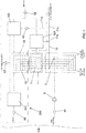
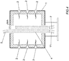
- FIG. 1 shows the cylindrical heating chamber 1, suitably insulated (for example by the use of refractory material or ecological ceramic fibres) inside which a plurality of burners 2 are placed ( Figs. 2 , 3 and 4 ).
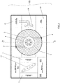
- Said burners 2 preferably heat a second cylindrical chamber 3, which is placed inside chamber 1 and at the central zone of said chamber 1, by direct contact with the flame of each burner placed tangentially with respect to said cylindrical chamber 3.
- catalytic tubes 4 Inside said cylindrical chamber 3 are housed catalytic tubes 4 ( Figs. 2 , 3 and 4 ) as described in detail here below.
- the endogas plant 100 provides, upstream of the heating chamber 1, a mixing system, illustrated in the dotted box in Fig. 1 and denoted overall by reference numeral 200, which is composed of a series of mixing units independent one from the other as will be described in detail here below.
- a first mixing unit of the mixing system 200 provides a mixing and regulation control unit 501 fed with nitrogen and optionally also with CO 2 , so as to produce:
- Said first control unit 501 then feeds a corresponding manifold 13 from which as many tubes 13i ( Fig. 2 ) as there are tubes 5 ( Fig. 2 ) for feeding the catalytic tubes 4 ( Fig. 2 ) branch off.
- shut-off valve 6in is mounted ( Fig. 2 ).
- the second mixing unit provides a second mixing and regulation unit 502 fed with air and methane, and optionally also with CO 2 , in the case wherein an endogas enriched with CO is to be obtained.
- said air is that in output from a cooler as will be explained in detail here below.
- said catalytic tubes or retorts 4 can be fed independently one from the other, each one via the corresponding feed tube 5 which is in fluid communication with the corresponding valve 6in, in turn in fluid communication with the respective tube 12i exiting the manifold 12 (containing air + methane and possibly also CO 2 ).
- valves 6in allow the catalytic tubes 4 to be excluded singly, in order to partialize the total flow of gas without changing significantly the speed of passage of the gas on the catalyst with respect to the nominal gas flow, as will be explained in detail here below.
- the selectable regulation means 6in which are advantageously in the form of automatic three-way valves, are fed, alternatively, by said mixing and control unit 501 or by said control and regulation unit 502.
- Said mixing/regulation system 200 in accordance with the invention also comprises, preferably, a third mixing and regulation unit 503 ( Fig. 1 ) dedicated to obtaining a binary mixture of air + methane for the combustion of burners 2 as will be described here below.
- the air used is that exiting the exchanger 7 so as to recover the heat from the cooling air and make a saving in fuel methane.
- Said control units 501, 502, 503 can be made in different ways, within the reach of the person skilled in the art, in order to achieve the objective of having, in the various flow lines 12i and 13i, mixtures with the desired compositions.
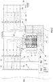
- Figure 2 illustrates in greater detail, and in section, the zone of endogas plant related to the catalytic reactor and a cooler 7.
- retorts 4 Inside said internal cylindrical chamber 3 is advantageously placed a plurality of catalytic tubes, or retorts 4, which are placed in parallel one in relation to the other and not in fluid communication one with the other. Said retorts 4 are preferably in a number higher than three.
- Each catalytic tube 4 is fed by a respective feed tube 5 which is in turn fed by a tube coming from manifold 12 or by a tube from manifold 13.
- a three-way shut-off valve 6in which regulates the influx in said tube 5 of the flow of the tube coming from manifold 12 or of the flow of the tube coming from manifold 13.
- each catalytic tube 4 is then cooled by means of at least one gas/air heat exchanger 7 whose construction allows to keep the gas flows in output from catalytic tubes 4 independent one from the other, as will be explained in detail here below.
- Said heat exchanger 7 is in the form of a duct, is placed outside the heating chamber 1 and contains in its interior a plurality of cooling tubes 11i, each one in fluid communication exclusively with the relative catalytic tube 4.
- Said heat exchanger 7 uses as cooling element air (whose flow is indicated in Fig. 2 by means of arrows), suitably filtered by a filter 64 ( Fig. 1 ) and aspirated by a fan 9 placed in the aspiration duct 8a of the cooling air 8.
- Each cooling tube 11i is in turn in fluid communication with a respective endogas output tube 20i on which a respective shut-off valve 6out is mounted.
- Each valve 6out is preferably a three-way valve, in turn connected, on one side, to an endogas use tube 21i and on the other side to a safety exhaust tube 22i.
- said heat exchanger 7 can contain only one cooling tube 11 associated with a respective catalytic tube 4 so that the number of exchangers 7 is equal to the number of catalytic tubes 4 provided in the present system.
- cooling tubes 11 for example the six tubes shown in Fig. 2 , in three gas/air heat exchangers 7 (and therefore in three cooling air aspiration ducts 8), in parallel one in relation to the other, each exchanger 7 being at the service of a pair of reaction tubes 4.
- This arrangement is particularly advantageous in conditions of running at partial speeds since it is possible to exclude one of the exchangers, improving the energy specifications.
- Each cooling tube 11 can then also be made as a tube bundle to increase the efficiency of the cooling system consisting of the exchanger 7 containing the cooling tubes 11.
- the function of the tube bundle is not only that of increasing the efficiency of the system by increasing the reaction or exchange surfaces, but to have a generator 100 whose total flow rate Q is the result of a series of independent tube bundles, each of which provides its own contribution for the achievement of the total flow rate.
- the cooling air in output from the exchanger 7 flows into a tube 70 from which three lines 71a, 71b, 71c ( Figure 1 ) branch off, where:
- Each valve 6in is controlled together with the corresponding valve 6out, creating an assembly for which, if a catalytic retort module 4-cooling tube 7 is fed with methane-air-CO 2 or methane-air mixture, the mixture produced is sent to the utility 21 - via the respective piping 21i - and if the same module is fed with N 2 -CO 2 or N 2 , the gases produced are sent to the exhaust in torch 22 via the respective pipeline 22i.
- the combustion fumes after having transferred their heat to internal chamber 3 and then to catalytic tubes 4, are generally discharged from the upper part of heating chamber 1 ( Fig. 2 ).
- Burners 2 are generally arranged in an opposing manner with respect to said inner cylindrical chamber 3 so as to form one or more groups of burners 2, each group of said burners 2 providing a series of burners 2 vertically aligned one in relation to the other ( Fig.1 and Fig.3 ). This arrangement allows the uniform heating of the whole external surface of said inner chamber 3 containing said retorts 4.
- Each of said burners 2 can be fed separately and independently or said burners 2 can be fed in groups via one or more manifolds (combustion system and manifolds not illustrated in the drawings). In this way it is possible to modulate the heating according to the number of catalytic tubes 4 fed and therefore as a function of the total flow rate in operation.
- Said tubular catalytic reactors or retorts 4 each have an inner diameter smaller than 100.0 mm, comprised between 50.0 and 99.9 mm.
- Each catalytic tube 4 is partially filled with an appropriate quantity of a specific catalyst for endogas based on noble metal oxides.
- This type of catalyst allows a higher spatial speed (in terms of hourly gas/catalyst volume flow rate), generally greater than 4,000 h-1, preferably equal to or greater than 10,000 h-1, more preferably in the order of at least 15,000 h-1 (i.e. at least 15 Nm 3 /h of reformed gas per litre of catalyst).
- the size is normally in balls of small diameter comprised between 2.5 and 5 mm, so as to have a high specific surface area and low pressure drops.
- Said catalytic tubes 4 are placed inside the inner chamber 3 in a substantially circular manner in the form of a tube bundle ( Fig. 2 and Fig. 3 ) so that they can all be irradiated by the inner chamber 3 in a homogeneous manner one in relation to the other, during their simultaneous feeding.
- the three-way valves 6in excluding singly one or more of said feed tubes 5 means that there is an overall flow Q in output from generator 100 which is lower than the nominal flow Qn for which the generator has been sized, said overall flow in operation Q being the sum of the flows Qi in each tube 4 which is in operation.
- This plant 100 with six tubes or retorts 4 is therefore capable of producing endogas with constant optimal composition even at feed flow rates reduced by 90% with respect to the nominal flow rate, advantageously comprised within the range of 50-200 Nm 3 /h.
- the exclusion of five of the six catalytic tubes 4 allows to obtain an optimal composition of the endogas with a flow rate reduced by 83% with respect to the nominal flow rate, a reduction normally not obtainable in the art with plants with one or two retorts.
- a control of the operating conditions of each catalytic tube 4 can be carried out by controlling the feed pressure, whose value depends on the pressure drops of the system and consequently on the level of soiling (sooting) of the catalyst.
- the present endogas generator 100 can be advantageously mounted on a skid and form a plug & play machine or plant that connects directly to the user's utilities (electricity, air, gas, etc.), without any specific technical assembly work, so as to be ready for use (turnkey).
- the present generator 100 also provides an electrical panel 10 on board the machine for the electrical power supply of the electrical machines necessary for its operation (fan 9, valves 6in and 6out, Lambda probe, etc.).
- Fan 9 is a high flow rate fan (e.g. > 5000 mc/h) which moves the air in duct 8 by cooling the gases produced as soon as they leave the catalyst located in the lower part of heating chamber 1.
- Each burner 2 can be advantageously fed with air aspirated at the outlet of the duct of exchanger 7, where the temperature is higher, in order to achieve energy recovery as previously described in relation to the mixing unit 503 that feeds the air+methane mixture to burners 2 ( Fig. 1 ).
- the feed air of the methane-air-CO 2 manifold in fluid communication with valves 6in, therefore with feed tubes 5 and reaction tubes 4, can be advantageously aspirated from the duct of the exchanger 7, realising a further energy recovery, as already described previously in relation to the mixing control unit 502 that feeds the air+methane mixture to the catalytic reactor comprising catalytic tubes 4 ( Fig. 2 ).
- said generator is the result of a series of sub-modules (six in the case of what is shown in Figures 1-3 where there are six catalytic tubes 4 and six respective cooling modules composed of one or more tubes 11i), by varying the number, and adapting the heating and cooling part, it is possible to realise sizes in the range 50-200 Nm 3 /h of endogas produced by varying the number of catalytic tubes 4 and corresponding rows in the exchanger for cooling 7.
- each catalytic tube 4 is sized to advantageously produce 15 - 20 mc/h of endogas, the 100 mc/h plant provides 6 modules and a 200 mc/h plant provides 12 modules. Likewise, the number of cooling modules 11 of the exchanger 7 is directly linked to the number of catalytic tubes 4.
- cooling is carried out advantageously with water and not with air.
- air instead of water, in an efficient manner thanks to the oversizing of exchanger 7 and of the air aspiration duct 8.
- the type of construction according to the present invention allows to cool the endogas produced immediately at the output from the heating chamber without the interposition of additional components that would limit the efficiency of the system in that the first section of tube would cool more slowly with respect to what takes place in the present invention.
- the endogas generator is a TOP-DOWN type system, i.e. with the feeding of the reaction mixture entering from the top of the catalytic reactor and the endogas exiting from the bottom of the catalytic reactor. It is understood, however, that this embodiment does not limit the object of the present invention and that it could be possible to use feeding of the reaction mixture from the bottom and an exit of the endogas from the top, without thereby departing from the scope of the present invention.
- the endothermic mixture produced by the present generator 100 is used both as a protective atmosphere in heat and/or surface treatments of metals (with respect to oxidation), and as a mixture able to confer certain mechanical properties to the metal subjected to the treatment, for example in the surface carburization of steel parts intended for mechanical members that must combine fatigue resistance with surface hardness and wear resistance.
Landscapes
- Chemical & Material Sciences (AREA)
- Chemical Kinetics & Catalysis (AREA)
- Organic Chemistry (AREA)
- Engineering & Computer Science (AREA)
- Materials Engineering (AREA)
- General Health & Medical Sciences (AREA)
- Health & Medical Sciences (AREA)
- Combustion & Propulsion (AREA)
- Inorganic Chemistry (AREA)
- Hydrogen, Water And Hydrids (AREA)
- Electrochromic Elements, Electrophoresis, Or Variable Reflection Or Absorption Elements (AREA)
- Radar Systems Or Details Thereof (AREA)
- Electroluminescent Light Sources (AREA)
Applications Claiming Priority (1)
| Application Number | Priority Date | Filing Date | Title |
|---|---|---|---|
| IT102019000015683A IT201900015683A1 (it) | 2019-09-05 | 2019-09-05 | Sistema modulabile per la generazione di endogas a contenuto di monossido di carbonio impostabile |
Publications (2)
| Publication Number | Publication Date |
|---|---|
| EP3789344A1 true EP3789344A1 (de) | 2021-03-10 |
| EP3789344B1 EP3789344B1 (de) | 2021-11-10 |
Family
ID=69173233
Family Applications (1)
| Application Number | Title | Priority Date | Filing Date |
|---|---|---|---|
| EP20187368.4A Active EP3789344B1 (de) | 2019-09-05 | 2020-07-23 | Modulierbares system zur erzeugung von endogas mit einstellbarem kohlenmonoxidgehalt |
Country Status (3)
| Country | Link |
|---|---|
| EP (1) | EP3789344B1 (de) |
| ES (1) | ES2900640T3 (de) |
| IT (1) | IT201900015683A1 (de) |
Cited By (2)
| Publication number | Priority date | Publication date | Assignee | Title |
|---|---|---|---|---|
| CN115007073A (zh) * | 2022-06-08 | 2022-09-06 | 滁州市润达溶剂有限公司 | 一种正庚烷溶剂油的脱芳烃装置 |
| US20250144611A1 (en) * | 2021-08-02 | 2025-05-08 | Velocys Technologies Ltd | Process for operating a plant facility during catalyst regeneration |
Citations (4)
| Publication number | Priority date | Publication date | Assignee | Title |
|---|---|---|---|---|
| GB2222096A (en) | 1988-04-12 | 1990-02-28 | Mitsubishi Gas Chemical Co | Reactor for reforming hydrocarbon and process for reforming hydrocarbon |
| US6191332B1 (en) * | 1991-05-06 | 2001-02-20 | Institut Francais Du Petrole | Method and apparatus for dehydrogenating aliphatic hydrocarbons to olefinic hydrocarbons |
| US20070293713A1 (en) * | 2002-11-13 | 2007-12-20 | Regents Of The University Of Minnesota | Catalytic partial oxidation of hydrocarbons |
| EP2851339A1 (de) | 2013-09-23 | 2015-03-25 | Rivoira S.p.A. | Modulsystem für die Erzeugung von Endogas |
-
2019
- 2019-09-05 IT IT102019000015683A patent/IT201900015683A1/it unknown
-
2020
- 2020-07-23 ES ES20187368T patent/ES2900640T3/es active Active
- 2020-07-23 EP EP20187368.4A patent/EP3789344B1/de active Active
Patent Citations (4)
| Publication number | Priority date | Publication date | Assignee | Title |
|---|---|---|---|---|
| GB2222096A (en) | 1988-04-12 | 1990-02-28 | Mitsubishi Gas Chemical Co | Reactor for reforming hydrocarbon and process for reforming hydrocarbon |
| US6191332B1 (en) * | 1991-05-06 | 2001-02-20 | Institut Francais Du Petrole | Method and apparatus for dehydrogenating aliphatic hydrocarbons to olefinic hydrocarbons |
| US20070293713A1 (en) * | 2002-11-13 | 2007-12-20 | Regents Of The University Of Minnesota | Catalytic partial oxidation of hydrocarbons |
| EP2851339A1 (de) | 2013-09-23 | 2015-03-25 | Rivoira S.p.A. | Modulsystem für die Erzeugung von Endogas |
Cited By (2)
| Publication number | Priority date | Publication date | Assignee | Title |
|---|---|---|---|---|
| US20250144611A1 (en) * | 2021-08-02 | 2025-05-08 | Velocys Technologies Ltd | Process for operating a plant facility during catalyst regeneration |
| CN115007073A (zh) * | 2022-06-08 | 2022-09-06 | 滁州市润达溶剂有限公司 | 一种正庚烷溶剂油的脱芳烃装置 |
Also Published As
| Publication number | Publication date |
|---|---|
| IT201900015683A1 (it) | 2021-03-05 |
| EP3789344B1 (de) | 2021-11-10 |
| ES2900640T3 (es) | 2022-03-17 |
Similar Documents
| Publication | Publication Date | Title |
|---|---|---|
| ES2681604T3 (es) | Reformado de hidrocarburos con vapor con exportación limitada de vapor | |
| CA2705640C (en) | Steam-hydrocarbon reforming with reduced carbon dioxide emissions | |
| US9512375B2 (en) | Method and apparatus for generating a methane-containing substitute natural gas and related energy supply system | |
| US8617266B2 (en) | Hydrogen generating apparatus using steam reforming reaction | |
| EP3789344B1 (de) | Modulierbares system zur erzeugung von endogas mit einstellbarem kohlenmonoxidgehalt | |
| US20010002248A1 (en) | Hydrogen generating apparatus | |
| MX2007010081A (es) | Preparacion de combustible de turbina de gas y metodo de introduccion. | |
| CN107344712A (zh) | 用于生产含氢产物的方法和装置 | |
| KR101353476B1 (ko) | 수소 제조 시스템 및 해당 시스템에 있어서의 오프가스의 유량 제어 방법 | |
| CN101102963A (zh) | 蒸汽甲烷重整方法 | |
| JP2014517806A (ja) | 改質段階を含み、動作条件が選択的に調整される、炭素材料からメタノール又は炭化水素を製造する方法 | |
| CN106631660B (zh) | 一种蒸汽裂解方法 | |
| WO2019093158A1 (ja) | 水素発生装置 | |
| KR101403699B1 (ko) | 열교환 장치를 내장한 일산화탄소 선택적 산화반응기 및 연료 개질 시스템 | |
| CN101735872A (zh) | 一种用于合成气生产的非定态反应器及生产合成气的方法 | |
| JP2021505499A (ja) | 水素含有ガスを得るための装置および方法 | |
| EP2851339B1 (de) | Modulsystem für die Erzeugung von Endogas | |
| KR20170022345A (ko) | 반응 효율이 우수한 탄화수소 수증기 개질용 촉매반응기 | |
| JP2013122372A (ja) | Voc含有ガスの処理方法 | |
| KR101480085B1 (ko) | 균일한 가스흐름 형성을 위한 가스분배기를 구비한 연료개질기 | |
| JP2015157732A (ja) | 水素生成装置、これを備えた燃料電池システム、水素生成装置の運転方法 | |
| EP2989048A1 (de) | Verfahren zur vorreformierung kohlenwasserstoffen | |
| CN106631661B (zh) | 一种蒸汽裂解方法 | |
| RU2851853C1 (ru) | Способ производства водорода из природного газа низкого давления и установка для его осуществления | |
| US5735970A (en) | Apparatus and process for the production of a neutral atmosphere |
Legal Events
| Date | Code | Title | Description |
|---|---|---|---|
| PUAI | Public reference made under article 153(3) epc to a published international application that has entered the european phase |
Free format text: ORIGINAL CODE: 0009012 |
|
| STAA | Information on the status of an ep patent application or granted ep patent |
Free format text: STATUS: THE APPLICATION HAS BEEN PUBLISHED |
|
| STAA | Information on the status of an ep patent application or granted ep patent |
Free format text: STATUS: REQUEST FOR EXAMINATION WAS MADE |
|
| AK | Designated contracting states |
Kind code of ref document: A1 Designated state(s): AL AT BE BG CH CY CZ DE DK EE ES FI FR GB GR HR HU IE IS IT LI LT LU LV MC MK MT NL NO PL PT RO RS SE SI SK SM TR |
|
| AX | Request for extension of the european patent |
Extension state: BA ME |
|
| 17P | Request for examination filed |
Effective date: 20210223 |
|
| RBV | Designated contracting states (corrected) |
Designated state(s): AL AT BE BG CH CY CZ DE DK EE ES FI FR GB GR HR HU IE IS IT LI LT LU LV MC MK MT NL NO PL PT RO RS SE SI SK SM TR |
|
| STAA | Information on the status of an ep patent application or granted ep patent |
Free format text: STATUS: EXAMINATION IS IN PROGRESS |
|
| 17Q | First examination report despatched |
Effective date: 20210420 |
|
| RAP3 | Party data changed (applicant data changed or rights of an application transferred) |
Owner name: NIPPON GASES INDUSTRIAL S.R.L. |
|
| GRAP | Despatch of communication of intention to grant a patent |
Free format text: ORIGINAL CODE: EPIDOSNIGR1 |
|
| STAA | Information on the status of an ep patent application or granted ep patent |
Free format text: STATUS: GRANT OF PATENT IS INTENDED |
|
| INTG | Intention to grant announced |
Effective date: 20210816 |
|
| GRAS | Grant fee paid |
Free format text: ORIGINAL CODE: EPIDOSNIGR3 |
|
| GRAA | (expected) grant |
Free format text: ORIGINAL CODE: 0009210 |
|
| STAA | Information on the status of an ep patent application or granted ep patent |
Free format text: STATUS: THE PATENT HAS BEEN GRANTED |
|
| AK | Designated contracting states |
Kind code of ref document: B1 Designated state(s): AL AT BE BG CH CY CZ DE DK EE ES FI FR GB GR HR HU IE IS IT LI LT LU LV MC MK MT NL NO PL PT RO RS SE SI SK SM TR |
|
| REG | Reference to a national code |
Ref country code: GB Ref legal event code: FG4D |
|
| REG | Reference to a national code |
Ref country code: AT Ref legal event code: REF Ref document number: 1445937 Country of ref document: AT Kind code of ref document: T Effective date: 20211115 Ref country code: CH Ref legal event code: EP |
|
| REG | Reference to a national code |
Ref country code: DE Ref legal event code: R096 Ref document number: 602020000966 Country of ref document: DE |
|
| REG | Reference to a national code |
Ref country code: DE Ref legal event code: R081 Ref document number: 602020000966 Country of ref document: DE Owner name: NIPPON GASES INDUSTRIAL S.R.L., IT Free format text: FORMER OWNER: NIPPON GASES INDUSTRIAL SRL, MILANO, IT |
|
| REG | Reference to a national code |
Ref country code: IE Ref legal event code: FG4D |
|
| REG | Reference to a national code |
Ref country code: LT Ref legal event code: MG9D |
|
| REG | Reference to a national code |
Ref country code: NL Ref legal event code: MP Effective date: 20211110 |
|
| REG | Reference to a national code |
Ref country code: ES Ref legal event code: FG2A Ref document number: 2900640 Country of ref document: ES Kind code of ref document: T3 Effective date: 20220317 |
|
| REG | Reference to a national code |
Ref country code: AT Ref legal event code: MK05 Ref document number: 1445937 Country of ref document: AT Kind code of ref document: T Effective date: 20211110 |
|
| PG25 | Lapsed in a contracting state [announced via postgrant information from national office to epo] |
Ref country code: RS Free format text: LAPSE BECAUSE OF FAILURE TO SUBMIT A TRANSLATION OF THE DESCRIPTION OR TO PAY THE FEE WITHIN THE PRESCRIBED TIME-LIMIT Effective date: 20211110 Ref country code: LT Free format text: LAPSE BECAUSE OF FAILURE TO SUBMIT A TRANSLATION OF THE DESCRIPTION OR TO PAY THE FEE WITHIN THE PRESCRIBED TIME-LIMIT Effective date: 20211110 Ref country code: FI Free format text: LAPSE BECAUSE OF FAILURE TO SUBMIT A TRANSLATION OF THE DESCRIPTION OR TO PAY THE FEE WITHIN THE PRESCRIBED TIME-LIMIT Effective date: 20211110 Ref country code: BG Free format text: LAPSE BECAUSE OF FAILURE TO SUBMIT A TRANSLATION OF THE DESCRIPTION OR TO PAY THE FEE WITHIN THE PRESCRIBED TIME-LIMIT Effective date: 20220210 Ref country code: AT Free format text: LAPSE BECAUSE OF FAILURE TO SUBMIT A TRANSLATION OF THE DESCRIPTION OR TO PAY THE FEE WITHIN THE PRESCRIBED TIME-LIMIT Effective date: 20211110 |
|
| PG25 | Lapsed in a contracting state [announced via postgrant information from national office to epo] |
Ref country code: IS Free format text: LAPSE BECAUSE OF FAILURE TO SUBMIT A TRANSLATION OF THE DESCRIPTION OR TO PAY THE FEE WITHIN THE PRESCRIBED TIME-LIMIT Effective date: 20220310 Ref country code: SE Free format text: LAPSE BECAUSE OF FAILURE TO SUBMIT A TRANSLATION OF THE DESCRIPTION OR TO PAY THE FEE WITHIN THE PRESCRIBED TIME-LIMIT Effective date: 20211110 Ref country code: PT Free format text: LAPSE BECAUSE OF FAILURE TO SUBMIT A TRANSLATION OF THE DESCRIPTION OR TO PAY THE FEE WITHIN THE PRESCRIBED TIME-LIMIT Effective date: 20220310 Ref country code: PL Free format text: LAPSE BECAUSE OF FAILURE TO SUBMIT A TRANSLATION OF THE DESCRIPTION OR TO PAY THE FEE WITHIN THE PRESCRIBED TIME-LIMIT Effective date: 20211110 Ref country code: NO Free format text: LAPSE BECAUSE OF FAILURE TO SUBMIT A TRANSLATION OF THE DESCRIPTION OR TO PAY THE FEE WITHIN THE PRESCRIBED TIME-LIMIT Effective date: 20220210 Ref country code: NL Free format text: LAPSE BECAUSE OF FAILURE TO SUBMIT A TRANSLATION OF THE DESCRIPTION OR TO PAY THE FEE WITHIN THE PRESCRIBED TIME-LIMIT Effective date: 20211110 Ref country code: LV Free format text: LAPSE BECAUSE OF FAILURE TO SUBMIT A TRANSLATION OF THE DESCRIPTION OR TO PAY THE FEE WITHIN THE PRESCRIBED TIME-LIMIT Effective date: 20211110 Ref country code: HR Free format text: LAPSE BECAUSE OF FAILURE TO SUBMIT A TRANSLATION OF THE DESCRIPTION OR TO PAY THE FEE WITHIN THE PRESCRIBED TIME-LIMIT Effective date: 20211110 Ref country code: GR Free format text: LAPSE BECAUSE OF FAILURE TO SUBMIT A TRANSLATION OF THE DESCRIPTION OR TO PAY THE FEE WITHIN THE PRESCRIBED TIME-LIMIT Effective date: 20220211 |
|
| PG25 | Lapsed in a contracting state [announced via postgrant information from national office to epo] |
Ref country code: SM Free format text: LAPSE BECAUSE OF FAILURE TO SUBMIT A TRANSLATION OF THE DESCRIPTION OR TO PAY THE FEE WITHIN THE PRESCRIBED TIME-LIMIT Effective date: 20211110 Ref country code: SK Free format text: LAPSE BECAUSE OF FAILURE TO SUBMIT A TRANSLATION OF THE DESCRIPTION OR TO PAY THE FEE WITHIN THE PRESCRIBED TIME-LIMIT Effective date: 20211110 Ref country code: RO Free format text: LAPSE BECAUSE OF FAILURE TO SUBMIT A TRANSLATION OF THE DESCRIPTION OR TO PAY THE FEE WITHIN THE PRESCRIBED TIME-LIMIT Effective date: 20211110 Ref country code: EE Free format text: LAPSE BECAUSE OF FAILURE TO SUBMIT A TRANSLATION OF THE DESCRIPTION OR TO PAY THE FEE WITHIN THE PRESCRIBED TIME-LIMIT Effective date: 20211110 Ref country code: DK Free format text: LAPSE BECAUSE OF FAILURE TO SUBMIT A TRANSLATION OF THE DESCRIPTION OR TO PAY THE FEE WITHIN THE PRESCRIBED TIME-LIMIT Effective date: 20211110 Ref country code: CZ Free format text: LAPSE BECAUSE OF FAILURE TO SUBMIT A TRANSLATION OF THE DESCRIPTION OR TO PAY THE FEE WITHIN THE PRESCRIBED TIME-LIMIT Effective date: 20211110 |
|
| REG | Reference to a national code |
Ref country code: DE Ref legal event code: R097 Ref document number: 602020000966 Country of ref document: DE |
|
| PLBE | No opposition filed within time limit |
Free format text: ORIGINAL CODE: 0009261 |
|
| STAA | Information on the status of an ep patent application or granted ep patent |
Free format text: STATUS: NO OPPOSITION FILED WITHIN TIME LIMIT |
|
| 26N | No opposition filed |
Effective date: 20220811 |
|
| PG25 | Lapsed in a contracting state [announced via postgrant information from national office to epo] |
Ref country code: AL Free format text: LAPSE BECAUSE OF FAILURE TO SUBMIT A TRANSLATION OF THE DESCRIPTION OR TO PAY THE FEE WITHIN THE PRESCRIBED TIME-LIMIT Effective date: 20211110 |
|
| PG25 | Lapsed in a contracting state [announced via postgrant information from national office to epo] |
Ref country code: MC Free format text: LAPSE BECAUSE OF FAILURE TO SUBMIT A TRANSLATION OF THE DESCRIPTION OR TO PAY THE FEE WITHIN THE PRESCRIBED TIME-LIMIT Effective date: 20211110 |
|
| REG | Reference to a national code |
Ref country code: BE Ref legal event code: MM Effective date: 20220731 |
|
| PG25 | Lapsed in a contracting state [announced via postgrant information from national office to epo] |
Ref country code: LU Free format text: LAPSE BECAUSE OF NON-PAYMENT OF DUE FEES Effective date: 20220723 Ref country code: FR Free format text: LAPSE BECAUSE OF NON-PAYMENT OF DUE FEES Effective date: 20220731 |
|
| PG25 | Lapsed in a contracting state [announced via postgrant information from national office to epo] |
Ref country code: BE Free format text: LAPSE BECAUSE OF NON-PAYMENT OF DUE FEES Effective date: 20220731 |
|
| PG25 | Lapsed in a contracting state [announced via postgrant information from national office to epo] |
Ref country code: IE Free format text: LAPSE BECAUSE OF NON-PAYMENT OF DUE FEES Effective date: 20220723 |
|
| REG | Reference to a national code |
Ref country code: CH Ref legal event code: PL |
|
| PG25 | Lapsed in a contracting state [announced via postgrant information from national office to epo] |
Ref country code: MK Free format text: LAPSE BECAUSE OF FAILURE TO SUBMIT A TRANSLATION OF THE DESCRIPTION OR TO PAY THE FEE WITHIN THE PRESCRIBED TIME-LIMIT Effective date: 20211110 Ref country code: CY Free format text: LAPSE BECAUSE OF FAILURE TO SUBMIT A TRANSLATION OF THE DESCRIPTION OR TO PAY THE FEE WITHIN THE PRESCRIBED TIME-LIMIT Effective date: 20211110 Ref country code: CH Free format text: LAPSE BECAUSE OF NON-PAYMENT OF DUE FEES Effective date: 20230731 |
|
| PG25 | Lapsed in a contracting state [announced via postgrant information from national office to epo] |
Ref country code: HU Free format text: LAPSE BECAUSE OF FAILURE TO SUBMIT A TRANSLATION OF THE DESCRIPTION OR TO PAY THE FEE WITHIN THE PRESCRIBED TIME-LIMIT; INVALID AB INITIO Effective date: 20200723 |
|
| PG25 | Lapsed in a contracting state [announced via postgrant information from national office to epo] |
Ref country code: MT Free format text: LAPSE BECAUSE OF FAILURE TO SUBMIT A TRANSLATION OF THE DESCRIPTION OR TO PAY THE FEE WITHIN THE PRESCRIBED TIME-LIMIT Effective date: 20211110 |
|
| GBPC | Gb: european patent ceased through non-payment of renewal fee |
Effective date: 20240723 |
|
| PG25 | Lapsed in a contracting state [announced via postgrant information from national office to epo] |
Ref country code: GB Free format text: LAPSE BECAUSE OF NON-PAYMENT OF DUE FEES Effective date: 20240723 |
|
| PGFP | Annual fee paid to national office [announced via postgrant information from national office to epo] |
Ref country code: ES Payment date: 20250827 Year of fee payment: 6 |
|
| PGFP | Annual fee paid to national office [announced via postgrant information from national office to epo] |
Ref country code: DE Payment date: 20250728 Year of fee payment: 6 |
|
| PG25 | Lapsed in a contracting state [announced via postgrant information from national office to epo] |
Ref country code: TR Free format text: LAPSE BECAUSE OF FAILURE TO SUBMIT A TRANSLATION OF THE DESCRIPTION OR TO PAY THE FEE WITHIN THE PRESCRIBED TIME-LIMIT Effective date: 20211110 |
|
| PG25 | Lapsed in a contracting state [announced via postgrant information from national office to epo] |
Ref country code: SI Free format text: LAPSE BECAUSE OF FAILURE TO SUBMIT A TRANSLATION OF THE DESCRIPTION OR TO PAY THE FEE WITHIN THE PRESCRIBED TIME-LIMIT Effective date: 20211110 |
|
| PG25 | Lapsed in a contracting state [announced via postgrant information from national office to epo] |
Ref country code: CH Free format text: THE PATENT HAS BEEN ANNULLED BY A DECISION OF A NATIONAL AUTHORITY Effective date: 20230731 |
|
| PGFP | Annual fee paid to national office [announced via postgrant information from national office to epo] |
Ref country code: IT Payment date: 20260623 Year of fee payment: 7 |