EP3789571A1 - Charnière dotée d'un mécanisme de levage/d'abaissement - Google Patents
Charnière dotée d'un mécanisme de levage/d'abaissement Download PDFInfo
- Publication number
- EP3789571A1 EP3789571A1 EP20204132.3A EP20204132A EP3789571A1 EP 3789571 A1 EP3789571 A1 EP 3789571A1 EP 20204132 A EP20204132 A EP 20204132A EP 3789571 A1 EP3789571 A1 EP 3789571A1
- Authority
- EP
- European Patent Office
- Prior art keywords
- hinge
- sliding surface
- counter
- rotation
- end faces
- Prior art date
- Legal status (The legal status is an assumption and is not a legal conclusion. Google has not performed a legal analysis and makes no representation as to the accuracy of the status listed.)
- Granted
Links
Images


Classifications
-
- E—FIXED CONSTRUCTIONS
- E05—LOCKS; KEYS; WINDOW OR DOOR FITTINGS; SAFES
- E05D—HINGES OR SUSPENSION DEVICES FOR DOORS, WINDOWS OR WINGS
- E05D11/00—Additional features or accessories of hinges
- E05D11/10—Devices for preventing movement between relatively-movable hinge parts
- E05D11/1028—Devices for preventing movement between relatively-movable hinge parts for maintaining the hinge in two or more positions, e.g. intermediate or fully open
- E05D11/1078—Devices for preventing movement between relatively-movable hinge parts for maintaining the hinge in two or more positions, e.g. intermediate or fully open the maintaining means acting parallel to the pivot
-
- E—FIXED CONSTRUCTIONS
- E05—LOCKS; KEYS; WINDOW OR DOOR FITTINGS; SAFES
- E05D—HINGES OR SUSPENSION DEVICES FOR DOORS, WINDOWS OR WINGS
- E05D3/00—Hinges with pins
- E05D3/06—Hinges with pins with two or more pins
- E05D3/08—Hinges with pins with two or more pins for swing-doors, i.e. openable by pushing from either side
-
- E—FIXED CONSTRUCTIONS
- E05—LOCKS; KEYS; WINDOW OR DOOR FITTINGS; SAFES
- E05D—HINGES OR SUSPENSION DEVICES FOR DOORS, WINDOWS OR WINGS
- E05D15/00—Suspension arrangements for wings
- E05D15/48—Suspension arrangements for wings allowing alternative movements
- E05D15/54—Suspension arrangements for wings allowing alternative movements for opening both inwards and outwards
-
- E—FIXED CONSTRUCTIONS
- E05—LOCKS; KEYS; WINDOW OR DOOR FITTINGS; SAFES
- E05F—DEVICES FOR MOVING WINGS INTO OPEN OR CLOSED POSITION; CHECKS FOR WINGS; WING FITTINGS NOT OTHERWISE PROVIDED FOR, CONCERNED WITH THE FUNCTIONING OF THE WING
- E05F1/00—Closers or openers for wings, not otherwise provided for in this subclass
- E05F1/02—Closers or openers for wings, not otherwise provided for in this subclass gravity-actuated, e.g. by use of counterweights
- E05F1/04—Closers or openers for wings, not otherwise provided for in this subclass gravity-actuated, e.g. by use of counterweights for wings which lift during movement, operated by their own weight
- E05F1/06—Mechanisms in the shape of hinges or pivots, operated by the weight of the wing
- E05F1/061—Mechanisms in the shape of hinges or pivots, operated by the weight of the wing with cams or helical tracks
- E05F1/063—Mechanisms in the shape of hinges or pivots, operated by the weight of the wing with cams or helical tracks with complementary, substantially identical and slidingly cooperating cam surfaces
-
- E—FIXED CONSTRUCTIONS
- E05—LOCKS; KEYS; WINDOW OR DOOR FITTINGS; SAFES
- E05Y—INDEXING SCHEME ASSOCIATED WITH SUBCLASSES E05D AND E05F, RELATING TO CONSTRUCTION ELEMENTS, ELECTRIC CONTROL, POWER SUPPLY, POWER SIGNAL OR TRANSMISSION, USER INTERFACES, MOUNTING OR COUPLING, DETAILS, ACCESSORIES, AUXILIARY OPERATIONS NOT OTHERWISE PROVIDED FOR, APPLICATION THEREOF
- E05Y2201/00—Constructional elements; Accessories therefor
- E05Y2201/60—Suspension or transmission members; Accessories therefor
- E05Y2201/622—Suspension or transmission members elements
- E05Y2201/638—Cams; Ramps
-
- E—FIXED CONSTRUCTIONS
- E05—LOCKS; KEYS; WINDOW OR DOOR FITTINGS; SAFES
- E05Y—INDEXING SCHEME ASSOCIATED WITH SUBCLASSES E05D AND E05F, RELATING TO CONSTRUCTION ELEMENTS, ELECTRIC CONTROL, POWER SUPPLY, POWER SIGNAL OR TRANSMISSION, USER INTERFACES, MOUNTING OR COUPLING, DETAILS, ACCESSORIES, AUXILIARY OPERATIONS NOT OTHERWISE PROVIDED FOR, APPLICATION THEREOF
- E05Y2900/00—Application of doors, windows, wings or fittings thereof
- E05Y2900/10—Application of doors, windows, wings or fittings thereof for buildings or parts thereof
- E05Y2900/112—Application of doors, windows, wings or fittings thereof for buildings or parts thereof for restrooms
-
- E—FIXED CONSTRUCTIONS
- E05—LOCKS; KEYS; WINDOW OR DOOR FITTINGS; SAFES
- E05Y—INDEXING SCHEME ASSOCIATED WITH SUBCLASSES E05D AND E05F, RELATING TO CONSTRUCTION ELEMENTS, ELECTRIC CONTROL, POWER SUPPLY, POWER SIGNAL OR TRANSMISSION, USER INTERFACES, MOUNTING OR COUPLING, DETAILS, ACCESSORIES, AUXILIARY OPERATIONS NOT OTHERWISE PROVIDED FOR, APPLICATION THEREOF
- E05Y2900/00—Application of doors, windows, wings or fittings thereof
- E05Y2900/10—Application of doors, windows, wings or fittings thereof for buildings or parts thereof
- E05Y2900/114—Application of doors, windows, wings or fittings thereof for buildings or parts thereof for showers
Definitions
- the present invention relates to a hinge with an inner hinge part and an inner fastening part connected thereto, with an outer hinge part and an outer fastening part connected thereto, with a central part connecting the two hinge parts, the inner hinge part and the central part for forming an inner axis of rotation by a inner hinge pins are rotatably connected to one another and the outer hinge part and the central part are rotatably connected to one another to form an outer axis of rotation by an outer hinge pin.
- swiveling doors are also quite common in addition to the known sliding doors.
- pivoting doors are equipped with a hinge with a lifting / lowering mechanism.
- the purpose of this type of hinge is to lower a second element into its closed position or zero position in order to ensure reliable sealing against a corresponding floor pan, the floor itself or a corresponding sealing edge.
- the movable element is raised accordingly by the raising / lowering mechanism.
- a seal which, in the closed position or zero position, is in contact with the floor pan, the floor or a sealing edge, for example, is free of contact during the pivoting movement, or is at least exposed to a significantly lower pressing force.
- this is gentle on the seal and wear is correspondingly reduced; on the other hand, due to the lower friction, the pivoting movement is much easier to carry out.
- a hinge with a lifting / lowering mechanism is also from the U.S. 3,398,487 A known, in which two interacting hinge parts have axially offset end faces which are connected to one another by inclined sliding surfaces, the sliding surfaces resting against one another and sliding against one another. With this hinge, a door should be reset to a defined zero position and the possibility of holding the door in an open position should be implemented.
- Swing doors i.e. doors which can be swiveled into the inside of the room as well as out of the room, are equipped with corresponding, known swing hinges for this purpose. These can have two hinge parts, each with an axis of rotation, which are connected to one another via a central part. Such a design with two axes of rotation allows a total swivel range of 360 °.
- a spring mechanism is arranged between the middle part and the respective hinge part.
- This spring mechanism ensures on the one hand that a second element or door leaf arranged on the pendulum hinge remains securely and without play in its closed position or zero position, and on the other hand that the connecting middle part cannot assume an undefined position.
- Undefined position is to be understood as meaning, for example, the "unfolding" of the two hinge parts and the middle part.
- the use of a spring mechanism allows a defined position to be taken repeatedly, such as the closed position or zero position, since the joints are pressed against corresponding stops or also into an equilibrium position due to the corresponding pretensioning by the springs.
- the springs at least compensate for the weight of the elements attached to the hinge or to the fastening parts and ensure that the two hinge parts and the middle part are held together.
- Hinges with a raising / lowering mechanism such as that in the DE 20 2007 001 139 U1 shown, sometimes have a relatively large pivoting range. However, it cannot be swiveled through 360 °. Both hinge parts have a common axis of rotation, as a result of which the pivoting range is inevitably restricted, since the two hinge parts come into contact with one another or against a door or wall element from a certain pivot angle / opening angle. Although the mechanism shown therein allows corresponding lifting and lowering, the lowered position is not clearly defined due to manufacturing tolerances, the occurrence of wear and a lack of spring mechanism. In order to allow a larger pivoting range, corresponding cutouts must be provided in the door element and / or wall element, into which the corresponding hinge parts can dip at a larger opening angle.
- the FR 1,110,877 A shows a hinge arrangement with an opening area of 180 ° in one direction.
- the hinge arrangement is formed by two hinges which are connected to one another via a rigid connecting part.
- end faces are provided, each with a tooth with flanks converging to a point and with different pitches. Due to the different slopes of the flanks of the teeth, the opening and closing behavior can be controlled by first activating the axis of rotation of a first hinge by sliding the flat flanks against each other and then activating the axis of rotation of the other hinge by sliding the steep flanks against each other.
- the hinge arrangement allows opening / closing in only one direction and thus does not form a pendulum hinge.
- the object of the present invention is to design a hinge with a raising / lowering mechanism that has as large a pivoting range as possible and eliminates the above-mentioned disadvantages with low component costs and high maintenance friendliness.
- the two hinge parts are each axially stepped to form two axially offset end faces in the area of the axis of rotation, the two axially offset end faces being connected to one another by a sliding surface and the sliding surface being inclined at an angle relative to the respective axis of rotation that the middle part is axially stepped to form at least two counter-end faces in the area of the axis of rotation, the two axially offset counter-end faces being connected to one another by a counter-sliding surface and the counter-sliding surface being aligned counter to the sliding surface, and that the sliding surface and the counter-sliding surface cooperate and lie against one another are arranged so as to slide against one another and in a zero position when the hinge is in the lowered state, the end faces do not come into contact with the mating end faces.
- a lifting / lowering function is implemented by sliding the sliding surface on the upper counter-sliding surface, with the sliding surfaces being inclined with respect to the respective axis of rotation. Due to the inclined sliding surfaces and the weight of one An element fastened to the fastening part, for example a second element, results in corresponding force components which ensure that the hinge returns to a zero position in which, for example, the second element is closed. The gap ensures that the hinge is held together in the zero position. This results in the lifting / lowering function for the entire possible pivoting range of the hinge. Regardless of which of the two axes of rotation the pivoting movement takes place, sliding surfaces inclined to the respective axis of rotation slide off one another and a lifting or lowering movement occurs.
- the two axially offset end faces of at least one hinge part are connected to one another by at least one further sliding surface and that the further sliding surface is inclined with respect to the respective axis of rotation with an orientation opposite to that of the sliding surface and that an opposing further counter sliding surface is provided on the middle part. Furthermore, it is provided that, in the event of a relative movement between at least one hinge part and the middle part, either an end face of at least one hinge part and a counter face of the middle part or the sliding surface and the counter sliding surface and the further sliding surface and the further counter sliding surface lie against one another and are arranged to slide against one another. As a result, the forces acting on the respective hinge part and on the middle part are divided between two sliding surfaces each, which reduces wear accordingly.
- the end face of at least one hinge part has a formation and a counter face of the central part has a counter formation and the formation and the counter formation lock releasably into one another when rotated about the respective axis of rotation by a certain angle.
- a connecting surface spaced from the sliding surface between the two end faces is designed as a stop and on the middle part an opposing connection surface spaced from the counter sliding surface between the two opposing end surfaces and as a counter stop.
- At least one of the two hinge parts and / or the central part has a bore coaxial to the respective axis of rotation into which an insert part with the end faces and the sliding surface and / or the further sliding surface and / or the formation and / or the stop or a mating insert part with the mating end faces and the mating sliding surface and / or the further mating sliding surface and / or the mating formation and / or the mating stop is inserted.
- the insert part and / or the counter-insert part have at least one radial circumferential surface with an elevation extending axially in the direction of the respective axis of rotation and / or a radial flattening and the coaxial bore to form an anti-rotation device is designed in a correspondingly opposed manner.
- the at least one anti-rotation device ensures that the insert part and / or the counter-insert part do not rotate within the bore coaxial to the respective axis of rotation in the respective hinge part and / or in the middle part.
- the insert part and / or the counter-insert part has at least one radial circumferential surface with at least one radially protruding elevation.
- Such radially protruding elevations for example in the form of a rib, make it possible to compensate for any tolerances between inserts and hinge parts and / or middle part and to avoid any play that occurs between the components.
- the insert part or the counter-insert part is arranged displaceably in the bore along the respective axis of rotation. This makes it possible to compensate for any play that may occur between the respective insert parts. In this way, any manufacturing tolerances that may arise or deviations in the course of assembly can be compensated for.
- the hinge is used in a door that can pivot on both sides, the inner fastening part of the inner hinge part being connected to a first element and the outer fastening part of the outer hinge part being connected to a second element.
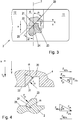
- Figure 1 shows the hinge 1 according to the invention in an exemplary installed state. How Figure 1 represents, the hinge 1 according to the invention is arranged between a second element 14 and a first element 13. As can be seen, the hinge 1 has an inner axis of rotation 7 and an outer axis of rotation 8.
- the first element 13 is formed by a stationary, immovable wall, a fastening rail, a fixed part of a partition or the like.
- the second element 14 forms a movable part, such as a door leaf, a movable flap or the like.
- the first element 13 is also designed as a movable part, the movable parts in the form of the first element 13 and the second element 14 with one another via at least one hinge 1 are connected and a plurality of first and second elements 13, 14 can be strung together.
- first element 13 is fixed and the second element 14 is movable.
- FIG. 2 shows the hinge 1 according to the invention in a dismantled state and with a sectional view rotated into the plane of view.
- the hinge 1 consists of at least three main parts.
- the inner hinge part 2 and the middle part 4 are used to form an inner one Axis of rotation 7, rotatably connected to one another by an inner hinge pin 5.
- the outer hinge part 3 and the middle part 4 are rotatably connected to one another by an outer hinge pin 6 to form an outer axis of rotation 8.
- the middle part 4 could just as well have one or both hinge pins 5 and 6.
- the inner axis of rotation 7 is preferably arranged axially parallel to the outer axis of rotation 8.
- two receiving bores 9 and 10 are made in the middle part 4.
- the receiving bore 9 is arranged axially parallel to the inner axis of rotation 7 and the receiving bore 10 is arranged axially parallel to the outer axis of rotation 8.
- the receiving bore 9 receives the hinge pin 5 of the inner hinge part 2 and the receiving bore 10 the hinge pin 6 of the outer hinge part 3, whereby the two hinge parts 2 and 3 are connected to one another via the middle part 4.
- the sectional view selected in the middle part 4 is rotated into the plane of view.
- one or both hinge pins 5, 6 are arranged in the middle part 4, the corresponding hinge parts 2 and / or 3 naturally have the receiving bores 9 and / or 10.
- other variants in which one or both hinge pins 5, 6 are arranged in the hinge parts 2, 3 are also conceivable.
- Combinations in which one hinge pin 5, 6 is arranged in a hinge part 2, 3 and the other hinge pin 5, 6 in the middle part 4 are also not excluded.
- the inner hinge part 2 has an inner fastening part 11 and the outer hinge part 3 has an outer fastening part 12.
- the hinge 1 is used in a bilateral pivotable one Doors, wherein the inner fastening part 11 of the inner hinge part 2 is connected to the first element 13, and the outer fastening part 12 of the outer hinge part 3 is connected to a second element 14.
- the first element 13 can be formed, for example, by a wall element or a mounting profile.
- the second element 14 is formed, for example, by a door element / door leaf.
- the fastening of the respective fastening part 11 and 12 on the first element 13 and on the second element 14 can take place as desired.
- screwing the individual fastening parts 11 and 12 to the first element 13 and the second element 14 is conceivable.
- a corresponding adhesive connection or any other suitable joining technique is also possible.
- the two hinge parts 2, 3 are each axially stepped to form two axially offset end faces 23, 25 in the area of the axis of rotation 7, 8.
- the two axially offset end faces 23, 25 are connected to one another by a sliding surface 24.
- the sliding surface 24 is inclined at an angle ⁇ with respect to the respective axis of rotation 7, 8.
- the middle part 4 is axially stepped to form at least two opposing end faces 20, 22 in the area of the axis of rotation 7, 8, the two axially offset opposing end faces 20, 22 being connected to one another by a counter sliding surface 21.
- the counter sliding surface 21 is aligned opposite to the sliding surface 24.
- the sliding surface 24 and the counter-sliding surface 21 are arranged to lie against one another and slide against one another.
- the weight T g acts through the dead weight of the second element 14.
- corresponding normal forces F 21 and F 24 result . These act normally on the sliding surfaces 21 and 24.
- the normal forces F 21 and F 24 can be broken down into horizontal and vertical force components F 21x and F 21z or F 24x and F 24z.
- the central part 4 counteracts the horizontal force component F 21x with a reaction force F R21x.
- the first hinge part 2 also counteracts the horizontal force component F 24x with a reaction force F R24x.
- the two reaction forces F R21x and F R24x lead to the same restoring effect, such as a spring mechanism between one of the hinge parts 2, 3 and the middle part 4.
- the force components mentioned ensure that there is no between the respective hinge part 2, 3 and the middle part 4 sets undefined position. The "cohesion" of a hinge part 2, 3 with the middle part 4 is thus ensured.
- a previously mentioned spring mechanism can be dispensed with.
- the angle ⁇ is in a range from 30 ° to 60 °.
- the angle ⁇ actually selected can depend on a wide variety of factors. For example, the material pairing and the surface properties of the two contacting sliding surfaces 21 and 24 must be taken into account. With higher surface roughness or poor sliding properties, the angle ⁇ must be selected to be smaller in order to produce a correspondingly high reaction force F R21x or F R24x .
- the force required to set the hinge 1 from a zero position in rotary motion is also dependent on the angle ⁇ .
- the normal forces F 21 and F 24 are dependent on the weight T g , that is to say on the dead weight of the second element 14.
- the hinge 1 can therefore be used equally for second elements 14 of different weights without having to adjust the hinge 1. Since the corresponding reaction forces F R21x and F R24x thus result depending on the weight of the second element 14 or weight force T g , the hinge 1 can also be referred to as "self-adjusting".
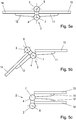
- the hinge 1 just described results in a rotary movement about at least one axis of rotation 7, 8, as shown in FIGS Figures 5a to 5c for the inner axis of rotation 7 is shown, through the sliding surface 24 and counter-sliding surface 24 inclined by the angle ⁇ , also a lifting or lowering movement.
- a second element 14 is connected to the outer hinge part 3 via an outer fastening part 12. If this second element 14 is relative to the exemplary first element 13 in the corresponding direction, that is, in the Figures 5a to 5c When rotated about the inner axis of rotation 7, the middle part 4 also executes this rotary movement.
- the middle part 4 is in contact with or abuts against the outer hinge part 3 or the outer fastening part 12, i.e. that outer, visible surfaces of the middle part 4 and the outer hinge part 3 or the outer fastening part 12 touch.
- a suitable damping element for example made of a suitable plastic, can also be provided between two components that are in contact in the area of the contact surface.
- the damping element can be arranged on any component or on both components.
- the second element 14 is raised relative to the first element 13 in the course of the rotary movement. How much the second element 14 is lifted depends on the amount by which the end faces 23, 25 or the mating end faces 20, 22 are axially stepped.
- the mentioned longitudinal movement or lifting movement in the direction of the inner axis of rotation 7 is carried out until, as a result of the rotational movement about the inner axis of rotation 7, the end face 23 of the inner hinge part 2 and the opposite end face 22 of the middle part 4 come into contact with one another. If the rotary movement about the inner axis of rotation 7 is continued, the end face 23 of the inner hinge part 2 and the opposite end face 22 of the middle part 4 slide against one another.
- the middle part 4 also comes into contact with the inner hinge part 2 or the inner fastening part 11.
- the continuation of the rotary movement about the inner axis of rotation 7 in the direction just described is no longer possible. If a force acts from the outside on the second element 14 fastened to the outer fastening part 12, the rotary movement is continued. However, the further rotary movement takes place again around the outer axis of rotation 8.
- the central part 4 remains in contact with the inner hinge part 2 or the inner fastening part 11 and does not perform the rotary movement about the outer axis of rotation 8.
- the zero position can therefore also be described as that position in which, with a continuous rotational movement around the entire pivoting range of the hinge 1, there is a change in the rotational axes 7, 8 around which the rotational movement takes place.
- the hinge 1 according to the invention realizes a lifting / lowering function.
- the lifting / lowering function ensures, for example, that a seal, which can be arranged on an edge of the second element 14 facing a floor, a floor pan or the like, during the pivoting movement of the second element 14 is lifted. On the one hand, this facilitates the pivoting movement due to the reduced friction, and on the other hand, the wear of such a seal is considerably reduced.
- the inner axis of rotation 7 and the outer axis of rotation 8 of the hinge 1 lie outside that plane which is formed by the second element 14 and / or the first element 13.
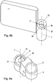
- Figures 6a and 6b shows the middle part 4 and the first hinge part 2 in a reduced configuration.
- the corresponding inner hinge pin 5 is not shown either in the middle part 4 or in the inner hinge part 2. As already mentioned, this could be arranged either in the middle part 4 or in the inner hinge part 2.
- the opposite end face 22 of the central part 4 is reduced to a minimum, whereby the function is not restricted further, however.
- the inner hinge part 2 is correspondingly shaped in opposite directions.
- the end face 25 of the inner hinge part 2 is also designed to be correspondingly reduced.
- the end face 23 can be in contact with the opposite end face 20 and the end face 25 with the opposite end face 22.
- the weight T g of the second element 14 is transmitted via the end faces 23, 25 and the opposing end faces 20, 22.
- the previously mentioned normal forces F 21 and F 24 resp. the reaction forces F R21x and F r24x therefore do not act. No forces with a restoring effect therefore act on the hinge part 2, 3.
- the hinge part 2, 3 remains in the zero position, except that corresponding forces are introduced from the outside, since, for example, the second element 14 is moved.
- the two axially offset end faces 23, 25 of at least one hinge part 2, 3 are connected to one another by at least one further sliding surface 124.
- the further sliding surface 124 is inclined with respect to the respective axis of rotation 7, 8 with an orientation opposite to that of the sliding surface 24.
- a counter-identical further counter-sliding surface 121 is provided on the middle part 4.
- the further sliding surface 124 and the further counter-sliding surface 121 are of course in contact with one another in the same way.
- the normal forces F 21 and F 24 as shown in Figure 4 are shown, divided on two sliding surfaces 24 and 124 or in the middle part 4 on two counter-sliding surfaces 21 and 121.
- the normal force acting in the respective sliding surface 21, 24 and counter-sliding surface 121, 124 becomes F 21 and F 24 halved and wear significantly reduced.
- the middle part 4 is correspondingly formed in opposite directions.
- the sliding surface 24 and the counter-sliding surface 21 or the further sliding surface 124 and the further counter-sliding surface 121 are arranged in a relative movement between at least one hinge part 2, 3 and the central part 4, interacting with one another and sliding against one another. Either an end face 23 of at least one hinge part 2, 3 and a counter face 22 of the middle part 4 or the sliding surface 24 and the counter sliding surface 21 or the further sliding surface 124 and the further counter sliding surface 121 are in contact with one another. In this way, the aforementioned reaction forces F R21x and F R24x result when the sliding surfaces 24, 124 and the counter-sliding surfaces 21, 121 are in contact with one another.
- the end face 23 of at least one hinge part 2, 3 has a recess 74 and a counter face 22 of the central part 4 has a counter formation 71.
- the formation 74 and the counter-formation 71 detachably lock into one another. If the second element 14 is pivoted so far that the end face 23 of a hinge part 2 or 3 and the opposite end face 22 of the middle part 4 are in contact with one another, there is the possibility that when pivoting further through a certain angle, the formation 74 can be released into the counter formation 71 clicks into place.
- the formation 74 and the counter formation 71 can, for example, by a hemispherical elevation and by an opposing, hemispherical indentation in the End face 23 and the opposite end face 22 may be formed. It is also conceivable that the formation 74 is designed as a counter formation 71 by a radial web pointing towards the inner axis of rotation 7 and an opposing radial groove. Such a variant of the counter-formation 71 is shown schematically in FIG Figure 6 recognizable. The contours of the formation 74 and the counter formation 71 are to be selected as far as possible in such a way that, in particular, disengagement or pivoting further or back is made possible without a considerable expenditure of force.
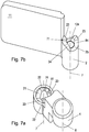
- a connecting surface between the two end surfaces 23 and 25 spaced apart from the sliding surface 24 is therefore designed as a stop 84.
- an opposing connecting surface, spaced apart from the opposing sliding surface 21, between the two opposing end surfaces 20 and 22 is designed as a counter stop 81.
- the corresponding axial stop 84 is in the Figures 6 and 7b good to see.
- the axial stop 84 is designed in such a way that the two end faces 25 and 23 are connected to one another in the form of a continuous surface.
- such a variant is only chosen as an example.
- the fact that the end faces 25 and 23 with the continuous surface just mentioned, by which the stop 84 is formed, enclose approximately 90 °, is merely exemplary.
- the weight of the second element 14 in this variant ensures a rotary movement about the respective axis of rotation 7, 8 until the stop 84 and the counter-stop 81 formed on the middle part 4 come into contact with one another.
- the middle part 4 and the two hinge parts 2, 3 can for example be shaped in such a way that there is no external contact between them in the zero position.
- the previously mentioned angle between the end faces 25, 23 and the stop 84 must therefore only be selected in such a way that a further rotary movement about the respective axis of rotation 7 or 8 is inhibited once a zero position has been reached.
- “inhibited” is to be understood as meaning that if the rotary movement is continued, the rotation axis 7, 8, about which the rotary movement is carried out, changes.
- the stop 84 or the counter-stop 81 does not necessarily have to be formed by a flat surface. Other variants, such as, for example, concave or opposite convex surfaces, are also quite conceivable.
- the arrangement of the middle part 4 or the arrangement of the stops can be freely selected to this effect. This or these could also be arranged in such a way that the middle part 4 does not carry out the rotary movement with a rotary movement about the inner rotary axis 7 and carries out the rotary movement with a rotary movement about the outer rotary axis 8.
- angle ⁇ of the sliding surfaces 21, 24 with respect to the inner axis of rotation 7 can have a different amount than with respect to the outer axis of rotation 8. This can result in a different pivoting behavior, depending on about which axis of rotation 7, 8 is pivoted. A larger angle ⁇ would, for example, enable pivoting with less effort.
- the amount by which the end faces 23, 25 or the opposing end faces 20, 22 are axially stepped can differ with regard to the inner axis of rotation 7 and the outer axis of rotation 8.
- the second element 14 is raised or lowered by a smaller amount than in the case of a rotary movement about the outer axis of rotation 8.
- a bore 36 coaxial with the respective axis of rotation 7, 8 is provided in the inner hinge part 2 or in the outer hinge part 3 or also in the middle part 4.
- the insert 54 has the end faces 23, 25, the sliding surface 24 and / or the further sliding surface 124 and / or the recess 74 and / or the stop 84.
- a counter insert part 51 can also be provided. This has the mating end faces 20, 22, the mating sliding surface 21 and / or the further mating sliding surface 121 and / or the mating formation 71 and / or the mating stop 81.
- the insert part 54 and the counter insert part 51 can for example be made of correspondingly wear-resistant materials which have the best possible sliding properties.
- PTFE generally known as Teflon®
- Teflon® is mentioned merely as an example. If insert parts 54 and counter insert parts 51 are provided in the inner hinge part 2 as well as in the outer hinge part 3 and in the middle part 4, the advantages come into play in the best possible way. However, it is also possible that an insert part 54 or also a counter-insert part 51 is provided only in the inner hinge part 2 or in the outer hinge part 3, which is then in contact with the correspondingly shaped middle part 4.
- the insert part 54 and / or the counter-insert part 51 has at least one radial circumferential surface 26 with an elevation 250 extending axially in the direction of the respective axis of rotation 7, 8 and / or a radial flattening 251 and the coaxial bore 36 for formation an anti-rotation device is designed in accordance with opposite.
- the at least one anti-twist device ensures that the insert part 54 and / or the counter-insert part 51 does not twist within the respective hinge part 2, 3 and / or in the middle part 4.
- FIGS 9 to 11 show an exemplary combination of possible versions of an anti-twist device.
- two elevations 250 extending axially in the direction of the axis of rotation are provided as an anti-rotation lock.
- the respective hinge part 2, 3 or the middle part 4 or the bore 36 must have corresponding grooves of the same opposite with which the elevations 250 can interact.
- that circumferential surface 26 which is intended to be arranged in a hinge part 2, 3 or in the middle part 4 can not be circular.
- a radial flattening 251 can be provided on the circumferential surface 26, for example.
- Figure 11 shows the in Figures 9 and 10 shown insert part 54 and the counter-insert part 51 in a displaced state along the corresponding axis of rotation 7, 8, whereby the hinge pin 5, 6 is visible.
- the mating end faces 20 and 22, the mating sliding surface 21, the mating stop 81 and the mating formation 71 on the mating insert part 51 can be seen.
- the formation 74 on the insert part 54 and the corresponding counter-formation 71 on the counter-insert part 51 are also shown to some extent.
- the hinge parts 2, 3 and the middle part 4 must also be adapted accordingly. If the hinge 1 is used, for example, in a shower partition, the angular position of the first element 13 to the second element 14 can be selected in the above-described zero position in this way.
- the insert part 54 or the counter insert part 51 is arranged around the respective axis of rotation 7, 8 in a certain angular position in the hinge part 2, 3 or in the middle part 4, the result is a corresponding positioning of the sliding surface 24 or, respectively, in relation to the axis of rotation 7, 8 of the counter-sliding surface 21 and also of all the other surfaces, formations and stops already mentioned.
- a polygonal, for example regular, hexagonal shower area in which one of the sides of a hexagonal shower partition is formed by the second element 14 in the form of a door element, there is between the second element 14 and an adjacent first element 13 an angle of 120 ° or 240 °, depending on whether measured from inside or outside the shower area.
- the insert part 54 and / or the counter-insert part 51 has at least one radial circumferential surface 26 with at least one radially protruding elevation 27.
- the radially protruding elevation 27 are in the Figures 8 to 11 particularly easy to recognize. It can be seen that a plurality of radially protruding elevations 27 can also be provided on the radial circumferential surface 26.
- the radially protruding elevations 27 increase the circumference of the radial circumferential surface 26 or the corresponding diameter.
- the aforementioned bores 36 therefore have, depending on the manufacturing tolerance, a diameter that is more or less too small to accommodate an insert part 54 and / or a counter-insert part 51.
- the protruding elevation 27 is correspondingly deformed or also removed, since the insert part 54 and / or the counter-insert part 51 are pressed into the "too small" bore.
- the insert part 54 and / or counter-insert part 51 adapts to the respective hinge part 2, 3 and / or the middle part 4 accordingly. In this way, the secure, play-free seat in the respective hinge part 2, 3 and / or the middle part 4 can be ensured.
- the insert part 54 or the counter-insert part 51 is arranged displaceably in the bore 36 along the respective axis of rotation 7, 8.
- the displaceable arrangement of the insert part 54 or the counter-insert part 51 in the respective hinge parts 2, 3 or the middle part 4, or in the respective bore 36, which can be displaced along the respective axis of rotation 7 or 8, allows any manufacturing tolerances or deviations that may arise during assembly , through the adjustability described.
- the resulting advantage can be seen in particular when two hinges 1 are used on, for example, a second element 14.
- two hinges 1 are used on, for example, a second element 14.
- only one of the two hinges 1 already has sliding surfaces 24 and Counter-sliding surface 21 and, for example, the stop 84 with the counter-stop 81 in contact.
- the dead weight of the second element 14 is now only absorbed by this one hinge 1, the normal forces F 21 and F 24 or the reaction forces F R21x and F do not result on the sliding surface 24 and the counter-sliding surface 21 of the second hinge 1 R24x .
- this can lead to the second hinge 1 assuming an undefined position already mentioned at the beginning.
- Figure 12 shows the central part 4 with the counter-insert parts 51 arranged therein by way of example.
- the two hinge pins 5, 6 are introduced into the respective counter-insert part 51 by way of example.
- a threaded bore 40 is provided in the central part 4. These lie coaxially to the respective axis of rotation 7, 8.
- a screw-in element 41 shown schematically as a screw with a hexagon socket, the respective counter-insert part 51 can be shifted in the direction of the respective axis of rotation 7, 8.
- the screw-in element 41 or the threaded hole 40 provided for it in the middle part 4 is covered by a cover 42. This prevents impurities from collecting on the screw-in element 41 or in the threaded hole 40.
- a fixing screw 44 can be provided as an additional safeguard for the axial position of the respective counter-insert part 51 set in this way.
- at least one further threaded bore 43 is provided in the middle part 4. This connects the outer contour of the middle part 4 with the respective bore 36 into which the counter-insert part 51 is inserted.
- the further threaded bore 43 lies in the area in which, when the counter-insert part 51 is inserted, its radial circumferential surface 26 comes to rest.
- the further threaded hole 43 is drawn in normal to the respective axis of rotation 7, 8.
- an adjustment or displacement mechanism just described can also be provided in the inner hinge part 2 and / or in the outer hinge part 3 for adjustment.
- a hinge 1 with a lifting / lowering mechanism is formed with a low component cost and high maintenance friendliness, which has the largest possible swivel range and, as already mentioned, is advantageously used for a bilateral swiveling second element 14.
- FIG Figure 13 In connection with the use for a door that can be pivoted on both sides, for example in connection with a shower partition, reference is made to a detail in FIG Figure 13 pointed out.
- the hinge 1 In Figure 13 the hinge 1 is shown in the dismantled state.
- Figure 13 shows, inter alia, a seal 90, consisting of a first sealing element 91 with a first fastening edge 92 and a first sealing edge 93, and a second sealing element 94 with a second fastening edge 95 and a second sealing edge 96.
- the first sealing element 91 has its first fastening edge 92 is fastened to the first element 13 and the second sealing element 94 is fastened with its second fastening edge 95 to the second element 14.
- the two sealing edges 93 and 96 contact one another in a manner that seals against one another.
- the two-part design of the seal 90 is only exemplary.
- a one-piece seal 90 can also be provided, which only has a first fastening edge 92 and a first sealing edge 93.
- the seal 90 is then fastened to the second element 14 with the first fastening edge 92 and contacts the first element 13 with the first sealing edge 93 in a sealing manner.
- a large number of other designs for the seal 90 are of course conceivable. Basically, it is important to prevent splash water from escaping into the outside area of the shower enclosure.
Landscapes
- Engineering & Computer Science (AREA)
- Mechanical Engineering (AREA)
- Hinges (AREA)
- Pivots And Pivotal Connections (AREA)
Applications Claiming Priority (2)
| Application Number | Priority Date | Filing Date | Title |
|---|---|---|---|
| ATA50915/2014A AT515252B1 (de) | 2014-12-17 | 2014-12-17 | Pendelscharnier |
| EP15200410.7A EP3034730B1 (fr) | 2014-12-17 | 2015-12-16 | Charnière dotée d'un mécanisme de levage/d'abaissement |
Related Parent Applications (2)
| Application Number | Title | Priority Date | Filing Date |
|---|---|---|---|
| EP15200410.7A Division-Into EP3034730B1 (fr) | 2014-12-17 | 2015-12-16 | Charnière dotée d'un mécanisme de levage/d'abaissement |
| EP15200410.7A Division EP3034730B1 (fr) | 2014-12-17 | 2015-12-16 | Charnière dotée d'un mécanisme de levage/d'abaissement |
Publications (2)
| Publication Number | Publication Date |
|---|---|
| EP3789571A1 true EP3789571A1 (fr) | 2021-03-10 |
| EP3789571B1 EP3789571B1 (fr) | 2024-11-06 |
Family
ID=53547636
Family Applications (2)
| Application Number | Title | Priority Date | Filing Date |
|---|---|---|---|
| EP15200410.7A Active EP3034730B1 (fr) | 2014-12-17 | 2015-12-16 | Charnière dotée d'un mécanisme de levage/d'abaissement |
| EP20204132.3A Active EP3789571B1 (fr) | 2014-12-17 | 2015-12-16 | Charnière dotée d'un mécanisme de levage/d'abaissement |
Family Applications Before (1)
| Application Number | Title | Priority Date | Filing Date |
|---|---|---|---|
| EP15200410.7A Active EP3034730B1 (fr) | 2014-12-17 | 2015-12-16 | Charnière dotée d'un mécanisme de levage/d'abaissement |
Country Status (2)
| Country | Link |
|---|---|
| EP (2) | EP3034730B1 (fr) |
| AT (1) | AT515252B1 (fr) |
Cited By (1)
| Publication number | Priority date | Publication date | Assignee | Title |
|---|---|---|---|---|
| EP4183954A1 (fr) * | 2021-11-23 | 2023-05-24 | Hartmut S. Engel | Système de portes optimisé au niveau de l'hygiène pour salles sanitaires |
Families Citing this family (8)
| Publication number | Priority date | Publication date | Assignee | Title |
|---|---|---|---|---|
| AT515252B1 (de) * | 2014-12-17 | 2018-01-15 | Artweger Gmbh & Co Kg | Pendelscharnier |
| DE102018001547A1 (de) | 2017-03-10 | 2018-09-13 | Schulte Duschkabinenbau Gmbh & Co. Kg | Beschlag und Duschabtrennung |
| DE102017211924A1 (de) * | 2017-07-12 | 2019-01-17 | Jungheinrich Aktiengesellschaft | Gelenkanordnung mit richtungsabhängigem Schwenkwiderstand |
| CN109805542B (zh) * | 2019-03-07 | 2024-07-05 | 正雄箱包(河源)有限公司 | 一种用于拉杆箱的合页装置以及拉杆箱 |
| AT522707B1 (de) | 2019-07-10 | 2023-05-15 | Artweger Gmbh & Co Kg | Vereinfachtes Pendelscharnier |
| DE202020000400U1 (de) | 2019-10-10 | 2020-02-18 | Schulte Duschkabinenbau Gmbh & Co Kg | Beschlag und Duschabtrennung |
| CN114802488B (zh) * | 2022-05-25 | 2023-10-17 | 徐工集团工程机械股份有限公司科技分公司 | 一种装载机车架新型铰接锁止机构 |
| CN218805686U (zh) * | 2022-11-28 | 2023-04-07 | 比亚迪股份有限公司 | 双向摆动装置以及车辆 |
Citations (12)
| Publication number | Priority date | Publication date | Assignee | Title |
|---|---|---|---|---|
| FR1110877A (fr) | 1954-07-28 | 1956-02-17 | L App Electro Ind Petrier | Perfectionnements aux charnières pour portes de coffrets, armoires et analogues |
| GB984616A (en) * | 1963-02-16 | 1965-02-24 | Friedrich Puchtler | Improvements in and relating to rising door hinges |
| US3398487A (en) | 1966-09-16 | 1968-08-27 | Matyas John | Swinging door construction |
| DE2129026A1 (de) * | 1970-06-19 | 1971-12-30 | Douglas, Jack Ernest, Walsall, Staffordshire (Großbritannien) | Abhebe- oder Hubangeln |
| GB2281099A (en) * | 1993-08-21 | 1995-02-22 | Kason Hardware | Self-closing door hinge |
| EP0777027A1 (fr) * | 1995-11-29 | 1997-06-04 | Torverk Torsby Verkstads Aktiebolag | Charnière de porte ou de portail |
| DE19649071A1 (de) * | 1996-11-28 | 1998-06-04 | Kienle Gmbh | Beschlag zum Befestigen eines Türflügels, insbesondere eines Türflügels einer Duschabtrennung aus Glas, Kunststoff oder dergleichen |
| CN2476629Y (zh) | 2001-06-11 | 2002-02-13 | 卢旭 | 双向开启自关合页 |
| DE202007001139U1 (de) | 2007-01-19 | 2008-02-28 | Altura Leiden Holding B.V. | Trennwand, insbesondere Duschtrennwand |
| DE202010008647U1 (de) * | 2010-09-28 | 2011-12-29 | Pauli + Sohn Gmbh Metallwaren | Gelenkband mit Hebe-Senkvorrichtung |
| US20130067687A1 (en) * | 2011-09-16 | 2013-03-21 | Kason Industries, Inc. | Heavy Duty Riser Hinge |
| AT515252A2 (de) * | 2014-12-17 | 2015-07-15 | Artweger Gmbh & Co Kg | Pendelscharnier |
Family Cites Families (3)
| Publication number | Priority date | Publication date | Assignee | Title |
|---|---|---|---|---|
| BE400951A (fr) * | ||||
| US1034008A (en) * | 1911-06-15 | 1912-07-30 | George E Toms | Gravity-hinge. |
| FR1259182A (fr) * | 1960-06-02 | 1961-04-21 | Perfectionnement aux charnières |
-
2014
- 2014-12-17 AT ATA50915/2014A patent/AT515252B1/de active
-
2015
- 2015-12-16 EP EP15200410.7A patent/EP3034730B1/fr active Active
- 2015-12-16 EP EP20204132.3A patent/EP3789571B1/fr active Active
Patent Citations (13)
| Publication number | Priority date | Publication date | Assignee | Title |
|---|---|---|---|---|
| FR1110877A (fr) | 1954-07-28 | 1956-02-17 | L App Electro Ind Petrier | Perfectionnements aux charnières pour portes de coffrets, armoires et analogues |
| GB984616A (en) * | 1963-02-16 | 1965-02-24 | Friedrich Puchtler | Improvements in and relating to rising door hinges |
| US3398487A (en) | 1966-09-16 | 1968-08-27 | Matyas John | Swinging door construction |
| DE2129026A1 (de) * | 1970-06-19 | 1971-12-30 | Douglas, Jack Ernest, Walsall, Staffordshire (Großbritannien) | Abhebe- oder Hubangeln |
| FR2099193A5 (fr) * | 1970-06-19 | 1972-03-10 | Douglas Jack | |
| GB2281099A (en) * | 1993-08-21 | 1995-02-22 | Kason Hardware | Self-closing door hinge |
| EP0777027A1 (fr) * | 1995-11-29 | 1997-06-04 | Torverk Torsby Verkstads Aktiebolag | Charnière de porte ou de portail |
| DE19649071A1 (de) * | 1996-11-28 | 1998-06-04 | Kienle Gmbh | Beschlag zum Befestigen eines Türflügels, insbesondere eines Türflügels einer Duschabtrennung aus Glas, Kunststoff oder dergleichen |
| CN2476629Y (zh) | 2001-06-11 | 2002-02-13 | 卢旭 | 双向开启自关合页 |
| DE202007001139U1 (de) | 2007-01-19 | 2008-02-28 | Altura Leiden Holding B.V. | Trennwand, insbesondere Duschtrennwand |
| DE202010008647U1 (de) * | 2010-09-28 | 2011-12-29 | Pauli + Sohn Gmbh Metallwaren | Gelenkband mit Hebe-Senkvorrichtung |
| US20130067687A1 (en) * | 2011-09-16 | 2013-03-21 | Kason Industries, Inc. | Heavy Duty Riser Hinge |
| AT515252A2 (de) * | 2014-12-17 | 2015-07-15 | Artweger Gmbh & Co Kg | Pendelscharnier |
Cited By (1)
| Publication number | Priority date | Publication date | Assignee | Title |
|---|---|---|---|---|
| EP4183954A1 (fr) * | 2021-11-23 | 2023-05-24 | Hartmut S. Engel | Système de portes optimisé au niveau de l'hygiène pour salles sanitaires |
Also Published As
| Publication number | Publication date |
|---|---|
| AT515252A3 (de) | 2016-01-15 |
| AT515252B1 (de) | 2018-01-15 |
| EP3034730B1 (fr) | 2022-02-23 |
| AT515252A2 (de) | 2015-07-15 |
| EP3789571B1 (fr) | 2024-11-06 |
| EP3034730A1 (fr) | 2016-06-22 |
Similar Documents
| Publication | Publication Date | Title |
|---|---|---|
| EP3034730B1 (fr) | Charnière dotée d'un mécanisme de levage/d'abaissement | |
| EP3612700B1 (fr) | Paroi de meuble avec un clapet et un corps de meuble et meuble avec une telle paroi de meuble | |
| EP3707331B1 (fr) | Paroi latérale d'un corps de meuble avec ferrure et meuble muni d'une paroi latérale | |
| DE60000108T2 (de) | Scharnier für einen zu öffnenden Tür- oder Fensterrahmen | |
| DE4345081C2 (de) | Scharnier für versenkt anzubringende Elektrohaushaltsgeräte | |
| DE4219681C2 (de) | Einstellbares Abhebescharnier | |
| DE202004000652U1 (de) | Scharnier | |
| EP3613931B1 (fr) | Module de bande destiné au raccordement mobile par charnière autour d'un axe de charnière d'un battant sur un cadre | |
| WO2018212724A1 (fr) | Bras de commande réglable en longueur | |
| WO2018033221A1 (fr) | Charnière de meuble | |
| DE69702628T2 (de) | Ein Scharnier für metallische Türen und Fenster | |
| DE202020000400U1 (de) | Beschlag und Duschabtrennung | |
| EP2902575B1 (fr) | Système de ferrure | |
| AT521462B1 (de) | Scharnier | |
| EP1153187B1 (fr) | Charniere a dispositif d'arret | |
| EP0467122A1 (fr) | Douille pour broches de ferrures ou charnières | |
| EP1781881B1 (fr) | Plaque de montage pour fixer de maniere mobile, des charnieres de meubles sur le corps de meubles | |
| EP2157266B1 (fr) | Charnière pour un article de mobilier doté d'une porte | |
| DE102013008211B4 (de) | Drehflügelbeschlag und Duschabtrennung | |
| EP1771635B1 (fr) | Penture a gond pour porte en verre | |
| EP3871575A1 (fr) | Charnière | |
| EP3278693B1 (fr) | Ferrure de porte coulissante | |
| DE102021109847B3 (de) | Schaltbares Türhebeband | |
| DE102013222890B4 (de) | Scharnieranordnung | |
| DE202018105626U1 (de) | Deckelbeschlag zum schwenkbaren Befestigen eines Deckels an einen Möbelkorpus und Möbel mit einem solchen Deckelbeschlag |
Legal Events
| Date | Code | Title | Description |
|---|---|---|---|
| PUAI | Public reference made under article 153(3) epc to a published international application that has entered the european phase |
Free format text: ORIGINAL CODE: 0009012 |
|
| STAA | Information on the status of an ep patent application or granted ep patent |
Free format text: STATUS: THE APPLICATION HAS BEEN PUBLISHED |
|
| AC | Divisional application: reference to earlier application |
Ref document number: 3034730 Country of ref document: EP Kind code of ref document: P |
|
| AK | Designated contracting states |
Kind code of ref document: A1 Designated state(s): AL AT BE BG CH CY CZ DE DK EE ES FI FR GB GR HR HU IE IS IT LI LT LU LV MC MK MT NL NO PL PT RO RS SE SI SK SM TR |
|
| STAA | Information on the status of an ep patent application or granted ep patent |
Free format text: STATUS: REQUEST FOR EXAMINATION WAS MADE |
|
| 17P | Request for examination filed |
Effective date: 20210908 |
|
| RBV | Designated contracting states (corrected) |
Designated state(s): AL AT BE BG CH CY CZ DE DK EE ES FI FR GB GR HR HU IE IS IT LI LT LU LV MC MK MT NL NO PL PT RO RS SE SI SK SM TR |
|
| GRAP | Despatch of communication of intention to grant a patent |
Free format text: ORIGINAL CODE: EPIDOSNIGR1 |
|
| STAA | Information on the status of an ep patent application or granted ep patent |
Free format text: STATUS: GRANT OF PATENT IS INTENDED |
|
| INTG | Intention to grant announced |
Effective date: 20240708 |
|
| P01 | Opt-out of the competence of the unified patent court (upc) registered |
Free format text: CASE NUMBER: APP_45999/2024 Effective date: 20240808 |
|
| GRAS | Grant fee paid |
Free format text: ORIGINAL CODE: EPIDOSNIGR3 |
|
| GRAA | (expected) grant |
Free format text: ORIGINAL CODE: 0009210 |
|
| STAA | Information on the status of an ep patent application or granted ep patent |
Free format text: STATUS: THE PATENT HAS BEEN GRANTED |
|
| AC | Divisional application: reference to earlier application |
Ref document number: 3034730 Country of ref document: EP Kind code of ref document: P |
|
| AK | Designated contracting states |
Kind code of ref document: B1 Designated state(s): AL AT BE BG CH CY CZ DE DK EE ES FI FR GB GR HR HU IE IS IT LI LT LU LV MC MK MT NL NO PL PT RO RS SE SI SK SM TR |
|
| REG | Reference to a national code |
Ref country code: GB Ref legal event code: FG4D Free format text: NOT ENGLISH |
|
| REG | Reference to a national code |
Ref country code: CH Ref legal event code: EP |
|
| REG | Reference to a national code |
Ref country code: DE Ref legal event code: R096 Ref document number: 502015016978 Country of ref document: DE |
|
| REG | Reference to a national code |
Ref country code: IE Ref legal event code: FG4D Free format text: LANGUAGE OF EP DOCUMENT: GERMAN |
|
| REG | Reference to a national code |
Ref country code: LT Ref legal event code: MG9D |
|
| REG | Reference to a national code |
Ref country code: NL Ref legal event code: MP Effective date: 20241106 |
|
| PG25 | Lapsed in a contracting state [announced via postgrant information from national office to epo] |
Ref country code: PT Free format text: LAPSE BECAUSE OF FAILURE TO SUBMIT A TRANSLATION OF THE DESCRIPTION OR TO PAY THE FEE WITHIN THE PRESCRIBED TIME-LIMIT Effective date: 20250306 Ref country code: HR Free format text: LAPSE BECAUSE OF FAILURE TO SUBMIT A TRANSLATION OF THE DESCRIPTION OR TO PAY THE FEE WITHIN THE PRESCRIBED TIME-LIMIT Effective date: 20241106 Ref country code: IS Free format text: LAPSE BECAUSE OF FAILURE TO SUBMIT A TRANSLATION OF THE DESCRIPTION OR TO PAY THE FEE WITHIN THE PRESCRIBED TIME-LIMIT Effective date: 20250306 |
|
| PG25 | Lapsed in a contracting state [announced via postgrant information from national office to epo] |
Ref country code: FI Free format text: LAPSE BECAUSE OF FAILURE TO SUBMIT A TRANSLATION OF THE DESCRIPTION OR TO PAY THE FEE WITHIN THE PRESCRIBED TIME-LIMIT Effective date: 20241106 Ref country code: NL Free format text: LAPSE BECAUSE OF FAILURE TO SUBMIT A TRANSLATION OF THE DESCRIPTION OR TO PAY THE FEE WITHIN THE PRESCRIBED TIME-LIMIT Effective date: 20241106 |
|
| PG25 | Lapsed in a contracting state [announced via postgrant information from national office to epo] |
Ref country code: BG Free format text: LAPSE BECAUSE OF FAILURE TO SUBMIT A TRANSLATION OF THE DESCRIPTION OR TO PAY THE FEE WITHIN THE PRESCRIBED TIME-LIMIT Effective date: 20241106 |
|
| PG25 | Lapsed in a contracting state [announced via postgrant information from national office to epo] |
Ref country code: ES Free format text: LAPSE BECAUSE OF FAILURE TO SUBMIT A TRANSLATION OF THE DESCRIPTION OR TO PAY THE FEE WITHIN THE PRESCRIBED TIME-LIMIT Effective date: 20241106 |
|
| PG25 | Lapsed in a contracting state [announced via postgrant information from national office to epo] |
Ref country code: NO Free format text: LAPSE BECAUSE OF FAILURE TO SUBMIT A TRANSLATION OF THE DESCRIPTION OR TO PAY THE FEE WITHIN THE PRESCRIBED TIME-LIMIT Effective date: 20250206 |
|
| PG25 | Lapsed in a contracting state [announced via postgrant information from national office to epo] |
Ref country code: LV Free format text: LAPSE BECAUSE OF FAILURE TO SUBMIT A TRANSLATION OF THE DESCRIPTION OR TO PAY THE FEE WITHIN THE PRESCRIBED TIME-LIMIT Effective date: 20241106 Ref country code: GR Free format text: LAPSE BECAUSE OF FAILURE TO SUBMIT A TRANSLATION OF THE DESCRIPTION OR TO PAY THE FEE WITHIN THE PRESCRIBED TIME-LIMIT Effective date: 20250207 |
|
| PGFP | Annual fee paid to national office [announced via postgrant information from national office to epo] |
Ref country code: CH Payment date: 20250122 Year of fee payment: 10 |
|
| PG25 | Lapsed in a contracting state [announced via postgrant information from national office to epo] |
Ref country code: PL Free format text: LAPSE BECAUSE OF FAILURE TO SUBMIT A TRANSLATION OF THE DESCRIPTION OR TO PAY THE FEE WITHIN THE PRESCRIBED TIME-LIMIT Effective date: 20241106 |
|
| PG25 | Lapsed in a contracting state [announced via postgrant information from national office to epo] |
Ref country code: RS Free format text: LAPSE BECAUSE OF FAILURE TO SUBMIT A TRANSLATION OF THE DESCRIPTION OR TO PAY THE FEE WITHIN THE PRESCRIBED TIME-LIMIT Effective date: 20250206 |
|
| PG25 | Lapsed in a contracting state [announced via postgrant information from national office to epo] |
Ref country code: SM Free format text: LAPSE BECAUSE OF FAILURE TO SUBMIT A TRANSLATION OF THE DESCRIPTION OR TO PAY THE FEE WITHIN THE PRESCRIBED TIME-LIMIT Effective date: 20241106 |
|
| PG25 | Lapsed in a contracting state [announced via postgrant information from national office to epo] |
Ref country code: DK Free format text: LAPSE BECAUSE OF FAILURE TO SUBMIT A TRANSLATION OF THE DESCRIPTION OR TO PAY THE FEE WITHIN THE PRESCRIBED TIME-LIMIT Effective date: 20241106 |
|
| PG25 | Lapsed in a contracting state [announced via postgrant information from national office to epo] |
Ref country code: EE Free format text: LAPSE BECAUSE OF FAILURE TO SUBMIT A TRANSLATION OF THE DESCRIPTION OR TO PAY THE FEE WITHIN THE PRESCRIBED TIME-LIMIT Effective date: 20241106 |
|
| PG25 | Lapsed in a contracting state [announced via postgrant information from national office to epo] |
Ref country code: RO Free format text: LAPSE BECAUSE OF FAILURE TO SUBMIT A TRANSLATION OF THE DESCRIPTION OR TO PAY THE FEE WITHIN THE PRESCRIBED TIME-LIMIT Effective date: 20241106 |
|
| PG25 | Lapsed in a contracting state [announced via postgrant information from national office to epo] |
Ref country code: SK Free format text: LAPSE BECAUSE OF FAILURE TO SUBMIT A TRANSLATION OF THE DESCRIPTION OR TO PAY THE FEE WITHIN THE PRESCRIBED TIME-LIMIT Effective date: 20241106 |
|
| PG25 | Lapsed in a contracting state [announced via postgrant information from national office to epo] |
Ref country code: CZ Free format text: LAPSE BECAUSE OF FAILURE TO SUBMIT A TRANSLATION OF THE DESCRIPTION OR TO PAY THE FEE WITHIN THE PRESCRIBED TIME-LIMIT Effective date: 20241106 |
|
| PG25 | Lapsed in a contracting state [announced via postgrant information from national office to epo] |
Ref country code: IT Free format text: LAPSE BECAUSE OF FAILURE TO SUBMIT A TRANSLATION OF THE DESCRIPTION OR TO PAY THE FEE WITHIN THE PRESCRIBED TIME-LIMIT Effective date: 20241106 |
|
| REG | Reference to a national code |
Ref country code: DE Ref legal event code: R097 Ref document number: 502015016978 Country of ref document: DE |
|
| PG25 | Lapsed in a contracting state [announced via postgrant information from national office to epo] |
Ref country code: LU Free format text: LAPSE BECAUSE OF NON-PAYMENT OF DUE FEES Effective date: 20241216 |
|
| PG25 | Lapsed in a contracting state [announced via postgrant information from national office to epo] |
Ref country code: SE Free format text: LAPSE BECAUSE OF FAILURE TO SUBMIT A TRANSLATION OF THE DESCRIPTION OR TO PAY THE FEE WITHIN THE PRESCRIBED TIME-LIMIT Effective date: 20241106 |
|
| PLBE | No opposition filed within time limit |
Free format text: ORIGINAL CODE: 0009261 |
|
| STAA | Information on the status of an ep patent application or granted ep patent |
Free format text: STATUS: NO OPPOSITION FILED WITHIN TIME LIMIT |
|
| PG25 | Lapsed in a contracting state [announced via postgrant information from national office to epo] |
Ref country code: MC Free format text: LAPSE BECAUSE OF FAILURE TO SUBMIT A TRANSLATION OF THE DESCRIPTION OR TO PAY THE FEE WITHIN THE PRESCRIBED TIME-LIMIT Effective date: 20241106 |
|
| REG | Reference to a national code |
Ref country code: BE Ref legal event code: MM Effective date: 20241231 |
|
| 26N | No opposition filed |
Effective date: 20250807 |
|
| PG25 | Lapsed in a contracting state [announced via postgrant information from national office to epo] |
Ref country code: BE Free format text: LAPSE BECAUSE OF NON-PAYMENT OF DUE FEES Effective date: 20241231 |
|
| PG25 | Lapsed in a contracting state [announced via postgrant information from national office to epo] |
Ref country code: FR Free format text: LAPSE BECAUSE OF NON-PAYMENT OF DUE FEES Effective date: 20250106 |
|
| PG25 | Lapsed in a contracting state [announced via postgrant information from national office to epo] |
Ref country code: IE Free format text: LAPSE BECAUSE OF NON-PAYMENT OF DUE FEES Effective date: 20241216 |
|
| GBPC | Gb: european patent ceased through non-payment of renewal fee |
Effective date: 20250206 |
|
| REG | Reference to a national code |
Ref country code: CH Ref legal event code: U11 Free format text: ST27 STATUS EVENT CODE: U-0-0-U10-U11 (AS PROVIDED BY THE NATIONAL OFFICE) Effective date: 20260101 |
|
| PG25 | Lapsed in a contracting state [announced via postgrant information from national office to epo] |
Ref country code: GB Free format text: LAPSE BECAUSE OF NON-PAYMENT OF DUE FEES Effective date: 20250206 |
|
| PGFP | Annual fee paid to national office [announced via postgrant information from national office to epo] |
Ref country code: AT Payment date: 20251223 Year of fee payment: 11 |
|
| PGFP | Annual fee paid to national office [announced via postgrant information from national office to epo] |
Ref country code: DE Payment date: 20251229 Year of fee payment: 11 |