EP3789590B1 - Synchronisierungsringdämpfer gegen pumpen - Google Patents
Synchronisierungsringdämpfer gegen pumpen Download PDFInfo
- Publication number
- EP3789590B1 EP3789590B1 EP20184327.3A EP20184327A EP3789590B1 EP 3789590 B1 EP3789590 B1 EP 3789590B1 EP 20184327 A EP20184327 A EP 20184327A EP 3789590 B1 EP3789590 B1 EP 3789590B1
- Authority
- EP
- European Patent Office
- Prior art keywords
- bumper
- synchronizing ring
- ring portion
- assembly
- recited
- Prior art date
- Legal status (The legal status is an assumption and is not a legal conclusion. Google has not performed a legal analysis and makes no representation as to the accuracy of the status listed.)
- Active
Links
Images


Classifications
-
- F—MECHANICAL ENGINEERING; LIGHTING; HEATING; WEAPONS; BLASTING
- F01—MACHINES OR ENGINES IN GENERAL; ENGINE PLANTS IN GENERAL; STEAM ENGINES
- F01D—NON-POSITIVE DISPLACEMENT MACHINES OR ENGINES, e.g. STEAM TURBINES
- F01D17/00—Regulating or controlling by varying flow
- F01D17/10—Final actuators
- F01D17/12—Final actuators arranged in stator parts
- F01D17/14—Final actuators arranged in stator parts varying effective cross-sectional area of nozzles or guide conduits
- F01D17/16—Final actuators arranged in stator parts varying effective cross-sectional area of nozzles or guide conduits by means of nozzle vanes
- F01D17/162—Final actuators arranged in stator parts varying effective cross-sectional area of nozzles or guide conduits by means of nozzle vanes for axial flow, i.e. the vanes turning around axes which are essentially perpendicular to the rotor centre line
-
- F—MECHANICAL ENGINEERING; LIGHTING; HEATING; WEAPONS; BLASTING
- F04—POSITIVE - DISPLACEMENT MACHINES FOR LIQUIDS; PUMPS FOR LIQUIDS OR ELASTIC FLUIDS
- F04D—NON-POSITIVE-DISPLACEMENT PUMPS
- F04D29/00—Details, component parts, or accessories
- F04D29/40—Casings; Connections of working fluid
- F04D29/52—Casings; Connections of working fluid for axial pumps
- F04D29/54—Fluid-guiding means, e.g. diffusers
- F04D29/541—Specially adapted for elastic fluid pumps
- F04D29/542—Bladed diffusers
Definitions
- the present invention relates to a gas turbine engine and, more particularly, to a synchronization ring therefor.
- Gas turbine engines such as those that power modern commercial and military aircraft, generally include a compressor section to pressurize an airflow, a combustor section to burn a hydrocarbon fuel in the presence of the pressurized air, and a turbine section to extract energy from the resultant combustion gases.
- variable stator vanes that can be pivoted about their individual axes to change an operational performance characteristic.
- the variable stator vanes are robustly designed to handle the stress loads that are applied to change the position of the vanes.
- a mechanical linkage is typically utilized to rotate the variable stator vanes. Because forces on the variable stator vanes can be relatively significant, forces transmitted through the mechanical linkage can also be relatively significant.
- Legacy designs typically utilize fueldraulic actuation to rotate the variable stator vanes.
- variable stator vanes are typically actuated by a synchronizing ring assembly.
- This synchronizing ring interfaces with the engine case via bumpers (also commonly called runners) that are either composite or metallic with a protective coating, depending on metal temperature.
- bumpers also commonly called runners
- US20140050567A1 discloses a surge bumper assembly that is part of a synchronizing ring assembly for gas turbine engines.
- the surge bumper assembly includes a bracket that is riveted or otherwise connected to the synchronizing ring adjacent a split in the synchronizing ring.
- US2015/184535 discloses an active synchronization ring that comprises a plurality of micro-actuators coupled to the synchronization ring to correct distortion in the synchronization ring.
- a synchronizing ring assembly according to one aspect of the invention is provided by claim 1.
- a further embodiment of any of the foregoing aspects or embodiments of the present disclosure includes that the synchronizing ring portion defines a first height throughout the span which extends along a ramp to the second height.
- a further embodiment of any of the foregoing aspects or embodiments of the present disclosure includes that the synchronizing ring portion is of a 180 degree arc length.
- each integrated surge bumper is of an arc length that is 2-5 % that of the synchronizing ring portion.
- a further embodiment of any of the foregoing aspects or embodiments of the present disclosure includes a multiple of bumper assemblies mounted to the synchronizing ring portion.
- each integrated surge bumper includes a clevis bridge bracket attachment passage.
- a further embodiment of any of the foregoing aspects or embodiments of the present disclosure includes a clevis bridge bracket attachment passage fastened to the to the synchronizing ring portion.
- a further embodiment of any of the foregoing aspects or embodiments of the present disclosure includes that the first and second synchronizing ring portion each defines a first height throughout a span and a second height at the first and second distal end to form the integrated surge bumper, each integrated surge bumper includes a clevis bridge bracket attachment passage.
- a method of controlling a deflection of a synchronizing ring assembly during a surge event in a gas turbine engine according to one aspect of the invention is provided by claim 13.
- a further embodiment of any of the foregoing aspects or embodiments of the present disclosure includes providing a rotational input to the synchronizing ring assembly through a clevis bridge bracket fastened to the synchronizing ring portion.
- FIG. 1 schematically illustrates a gas turbine engine 20.
- the gas turbine engine 20 is disclosed herein as a two-spool GTF (geared turbofan) that generally incorporates a fan section 22, a compressor section 24, a combustor section 26 and a turbine section 28.
- Alternative engine architectures might include an augmentor section and exhaust duct section (not shown) among other systems or features.
- the fan section 22 drives air along a bypass flowpath while the compressor section 24 drives air along a core flowpath for compression and communication into the combustor section 26 then expansion thru the turbine section 28.
- an intermediate spool includes an intermediate pressure compressor ("IPC") between a Low Pressure Compressor (“LPC”) and a High Pressure Compressor (“HPC”), and an intermediate pressure turbine (“IPT”) between the high pressure turbine (“HPT”) and the Low pressure Turbine (“LPT”).
- IPC intermediate pressure compressor
- LPC Low Pressure Compressor
- HPC High Pressure Compressor
- IPT intermediate pressure turbine
- the engine 20 generally includes a low spool 30 and a high spool 32 mounted for rotation about an engine central longitudinal axis A relative to an engine static structure 36 via several bearing compartments 38.
- the low spool 30 generally includes an inner shaft 40 that interconnects a fan 42, a low pressure compressor 44 ("LPC") and a low pressure turbine 46 ("LPT").
- the inner shaft 40 drives the fan 42 directly or thru a geared architecture 48 to drive the fan 42 at a lower speed than the low spool 30.
- An exemplary reduction transmission is an epicyclic transmission, namely a planetary or star gear system.
- the high spool 32 includes an outer shaft 50 that interconnects a high pressure compressor 52 ("HPC") and high pressure turbine 54 ("HPT").
- a combustor 56 is arranged between the HPC 52 and the HPT 54.
- the inner shaft 40 and the outer shaft 50 are concentric and rotate about the engine central longitudinal axis A which is collinear with their longitudinal axes.
- the gas turbine engine 20 is a high-bypass geared aircraft engine with a bypass ratio greater than about six (6:1).
- the geared architecture 48 can include an epicyclic gear train, such as a planetary gear system or other gear system.
- the example epicyclic gear train has a gear reduction ratio of greater than about 2.3:1, and in another example is greater than about 3.0:1.
- the geared turbofan enables operation of the low spool 30 at higher speeds which can increase the operational efficiency of the LPC 44 and LPT 46 to render increased pressure in relatively few stages.
- a pressure ratio associated with the LPT 46 is pressure measured prior to the inlet of the LPT 46 as related to the pressure at the outlet of the LPT 46 prior to an exhaust nozzle of the gas turbine engine 20.
- the bypass ratio of the gas turbine engine 20 is greater than about ten (10:1)
- the fan diameter is significantly larger than that of the LPC 44
- the LPT 46 has a pressure ratio that is greater than about five (5:1). It should be understood, however, that the above parameters are only exemplary of one embodiment of a geared architecture engine and that the present disclosure is applicable to other gas turbine engines including direct drive turbofans, where the rotational speed of the fan 42 is the same (1:1) of the LPC 44.
- a significant amount of thrust is provided by the bypass flow path due to the high bypass ratio.
- the fan section 22 of the gas turbine engine 20 is designed for a particular flight condition - typically cruise at about 0.8 Mach and about 35,000 feet (10668 meters). This flight condition, with the gas turbine engine 20 at its best fuel consumption, is also known as bucket cruise Thrust Specific Fuel Consumption (TSFC).
- TSFC Thrust Specific Fuel Consumption
- Fan Pressure Ratio is the pressure ratio across a blade of the fan section 22 without the use of a Fan Exit Guide Vane system.
- the relatively low Fan Pressure Ratio according to one example gas turbine engine 20 is less than 1.45.
- the Low Corrected Fan Tip Speed according to one example gas turbine engine 20 is less than about 1150 fps (351 m/s).
- one or more stages of the LPC 44 and/or the HPC 52 include a variable vane system 100 that can be rotated to change an operational performance characteristic of the gas turbine engine 20 for different operating conditions.
- the variable vane system 100 may include one or more variable vane stages.
- the variable vane system 100 may include a plurality of variable stator vanes 102 (also shown in FIG. 3 ) circumferentially arranged around the engine central axis A.
- the variable stator vanes 102 each include a variable vane body that has an airfoil portion that provides a lift force via Bernoulli's principle such that one side of the airfoil portion generally operates as a suction side and the opposing side of the airfoil portion generally operates as a pressure side.
- Each of the variable stator vanes 102 generally spans between an inner diameter and an outer diameter relative to the engine central axis A.
- Each of the variable stator vanes 102 includes an inner pivot pin 104 that is receivable into a corresponding socket (not shown) and an outer trunion 106 mounted through an outer engine case 108 such that each of the variable stator vanes 102 can pivot about a vane axis V ( FIG. 3 ).
- variable vane system 100 further includes a synchronizing ring assembly 110 to which, in one disclosed non-limiting embodiment, each of the outer trunions 106 are attached through a vane arm 112 along a respective axis D. It should be appreciated that although a particular vane arm 112 is disclosed in this embodiment, various linkages of various geometries may be utilized.
- variable vane system 100 is driven by an actuator system 118 with an actuator 120, a drive 122 and an actuator arm 124 (also shown in FIG. 4 ).
- actuator system 118 with an actuator 120, a drive 122 and an actuator arm 124 (also shown in FIG. 4 ).
- the synchronizing ring assembly 110 includes a first synchronizing ring portion 130, a second synchronizing ring portion 132, and a first and second clevis bridge bracket 140, 142 attached therebetween to bridge the first and second synchronizing ring portion 130, 132. Segregating the synchronizing ring assembly 110 permits the first and second clevis bridge bracket 140, 142 to bridge the split flange 109 typically located in the outer engine case 108.
- the first and second clevis bridge bracket 140, 142 are each driven by the actuator arm 124 of the actuator system 118.
- the vane torque creates clockwise torque on the synchronizing ring assembly 110 which is constrained at the clevis bridge bracket attachment points 150 ( FIG. 6 ).
- the synchronizing ring assembly 110 deflects inboard at that location, and outboard 90° away such that the vane arms 112 located 90° away may fail if the deflection is too great ( FIG. 7 ).
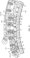
- the synchronizing ring assembly 110 is at least partially supported on the outer engine case 108 by a multiple of bumper assemblies 160.
- five bumper assemblies 160 are mounted to each of the first and second synchronizing ring portion 130, 132.
- Each bumper assembly 160 include a bumper 162 mounted to the respective first and second synchronizing portions 130, 132 via a threaded fastener 164.
- the threaded fastener 164 includes a head 166 that fits within the bumper 162 and a nut 168 that is threaded to the threaded fastener 164 to retain the bumper 162.
- the bumper 162 provides a build gap greater than a minimum gap with respect to an outer surface 170 of the outer engine case 108. Adjustment may be performed via the threaded fastener 164.
- Each of the first and second synchronizing ring portion 130, 132 have distal ends 134 that form integrated surge bumpers 180. That is, the surge bumpers 180 are protuberances on an inner diameter of each synchronizing ring portion 130, 132 nearest to the case split flange 109 such that the first and second synchronizing ring portion 130, 132 define a first height 182 throughout the span which then increases to a second height 184 at the distal end. The first and second heights may smoothly interface via a ramp 186.
- the distal ends 134 that form the integrated surge bumpers 180 are each of an arc length that is 2-5 % of each synchronizing ring portion 130, 132 and, each ring half is about 160° of the overall engine.
- the surge bumpers 180 provide a build gap greater than a minimum gap with respect to the outer surface 170 of the outer engine case 108.
- the surge bumpers 180 build gap is 4-5 times that of the bumper 162 and the minimum gap is 15-17 times that of the bumper 162.
- the normal bumper gaps are set to a minimum so as to keep the ring as circular as possible during operation (the loads deflect the ring into an oval; the higher the load and the larger the gap the more the deflection). The more circular the ring is, the more uniform the variable vane angles are, which translates to better performance. However, if the gaps are too small, the sync ring could bind during an acceleration where the case grows too fast and the sync rings can't catch up, so you do need to have some gap.
- the surge bumpers 180 need not be coated, and features a larger inner diameter than the regular bumpers so as to not touch the outer engine case during normal operation. During a surge event where excessive deflection occurs, the surge bumper 180 will contact the outer engine case and prevent any further deflection thereby protecting the drive arms 112.
- the first and second synchronizing ring portion 130, 132 include a multiple of passages 190 that receive bushings 192.
- Each bushing 192 supports a respective drive pin 194 which, in turn, link the respective vane arms 112 to the synchronizing ring assembly 110 ( FIG. 2 ).
- the first and second synchronizing ring portion 130, 132 likewise include a at least one clevis bridge bracket attachment passages 200.
- the clevis bridge bracket attachment passages 200 receive bushings 202 that support a nut 204 of a threaded fastener 206 that passes through the respective first and second synchronizing ring portion 130, 132 and the first and second clevis bridge bracket 140, 142.
- At least one clevis bridge bracket attachment passages 200 is positioned to pass through the second height 184 of each surge bumper 180.
- the surge bumpers 180 limit the radial deflection during a high powered surge, where tight vane spacing prevents location of a bumper assembly close to the case split flange.
- the surge bumpers 180 are also lighter than a regular bumper assembly and without the surge bumpers 180, significant stiffness would have to otherwise be provided into the synchronizing ring, either of a tubular or I-beam type, which would be a detriment to product weight.
Landscapes
- Engineering & Computer Science (AREA)
- Mechanical Engineering (AREA)
- General Engineering & Computer Science (AREA)
- Retarders (AREA)
- Structures Of Non-Positive Displacement Pumps (AREA)
Claims (14)
- Synchronisierungsringanordnung, umfassend:einen Synchronisierungsringabschnitt (130, 132), der ein erstes distales Ende und ein zweites distales Ende (134) aufweist, wobei das erste distale Ende und das zweite distale Ende (134) jeweils einen integrierten Pumpdämpfer (180) bilden, wobei der Synchronisierungsringabschnitt (130, 132) eine erste Höhe (182) über eine Spannweite, die an jedem distalen Ende (134) auf eine zweite Höhe (184) ansteigt, um den integrierten Pumpdämpfer (180) zu bilden, definiert; undeine Dämpferanordnung (160), die an dem Synchronisierungsringabschnitt montiert ist, wobei ein Bauspalt des integrierten Pumpdämpfers (180) in Bezug auf eine Außenoberfläche (170) eines Außengehäuses (108) das 4-5-Fache eines Bauspalts der Dämpferanordnung in Bezug auf die Außenoberfläche (170) des Außengehäuses (108) beträgt.
- Anordnung nach Anspruch 1, wobei der Synchronisierungsringabschnitt die erste Höhe (182) über die Spannweite definiert, die sich entlang einer Rampe (186) zu der zweiten Höhe (184) erstreckt.
- Anordnung nach Anspruch 1 oder 2, wobei der Synchronisierungsringabschnitt eine Bogenlänge von 180 Grad aufweist.
- Anordnung nach Anspruch 1, 2 oder 3, wobei jeder integrierte Pumpdämpfer (180) eine Bogenlänge von 2-5 % derjenigen des Synchronisierungsringabschnitts aufweist.
- Anordnung nach einem vorstehenden Anspruch, die ferner eine Vielzahl von Dämpferanordnungen (160), die an dem Synchronisierungsringabschnitt montiert sind, umfasst.
- Anordnung nach einem vorstehenden Anspruch, wobei jeder integrierte Pumpdämpfer (180) einen Gabelbrückenhalterungs-Befestigungsdurchgang (200) beinhaltet.
- Anordnung nach Anspruch 6, die ferner eine Gabelbrückenhalterung (140, 142), die an dem Synchronisierungsringabschnitt befestigt ist, umfasst.
- Synchronisierungsringanordnung, umfassend:einen ersten und einen zweiten Synchronisierungsringabschnitt (130), jeweils gemäß einem Synchronisierungsringabschnitt (130, 132) des Anspruchs 1;eine erste Gabelbrückenhalterung (140), die an dem ersten Synchronisierungsringabschnitt (130) und dem zweiten Synchronisierungsringabschnitt (132) befestigt ist;eine zweite Gabelbrückenhalterung (142), die an dem ersten Synchronisierungsringabschnitt (130) und dem zweiten Synchronisierungsringabschnitt (132) befestigt ist;eine Vielzahl von Dämpferanordnungen (160), die an dem ersten Synchronisierungsringabschnitt (130) befestigt ist; undeine Vielzahl von Dämpferanordnungen (160), die an dem zweiten Synchronisierungsringabschnitt (132) befestigt sind.
- Anordnung nach Anspruch 8, wobei der erste und der zweite Synchronisierungsringabschnitt (130, 132) jeweils eine erste Höhe (182) über eine Spannweite und eine zweite Höhe (184) an dem ersten und dem zweiten distalen Ende (134) definieren, um den integrierten Pumpdämpfer (180) zu bilden, wobei jeder integrierte Pumpdämpfer (180) einen Gabelbrückenhalterungs-Befestigungsdurchgang (200) beinhaltet.
- Anordnung nach einem vorstehenden Anspruch, wobei der Bauspalt jedes integrierten Pumpdämpfers (180) größer als ein minimaler Spalt in Bezug auf die Außenoberfläche (170) des Außengehäuses (108) ist.
- Anordnung nach einem vorstehenden Anspruch, wobei der Bauspalt der oder jeder Dämpferanordnung (160) größer als ein minimaler Spalt in Bezug auf die Außenoberfläche (170) des Außengehäuses (108) ist.
- Anordnung nach einem vorstehenden Anspruch, wobei der oder die minimalen Spalten des integrierten Pumpdämpfers (180) das 15- bis 17-Fache der einer oder der Dämpferanordnung beträgt.
- Verfahren zum Steuern einer Durchbiegung einer Synchronisierungsringanordnung nach Anspruch 1, während eines Pumpereignisses in einem Gasturbinentriebwerk, das Folgendes umfasst:Bereitstellen des Bauspalts in Bezug auf die Außenoberfläche (170) des äußeren Motorgehäuses (108) für den integrierten Pumpdämpfer (180), der an jedem distalen Ende (134) des Synchronisierungsringabschnitts (130, 132) gebildet ist, der das 4- bis 5-Fache derjenigen der Dämpferanordnung (160), die an dem Synchronisierungsringabschnitt (130, 132) angebracht ist, beträgt; undBereitstellen eines minimalen Spalts in Bezug auf die Außenoberfläche (170) des äußeren Motorgehäuses (108) für den integrierten Pumpdämpfer (180), der an jedem distalen Ende (134) des Synchronisierungsringabschnitts (130, 132) gebildet ist, der das 15- bis 17-Fache derjenigen der Dämpferanordnung (160), die an dem Synchronisierungsringabschnitt (130, 132) angebracht ist, beträgt.
- Verfahren nach Anspruch 13, das ferner das Bereitstellen einer Rotationseingabe zu der Synchronisierungsringanordnung durch eine Gabelbrückenhalterung (142), die an dem Synchronisierungsringabschnitt (130, 132) befestigt ist, umfasst.
Applications Claiming Priority (1)
| Application Number | Priority Date | Filing Date | Title |
|---|---|---|---|
| US16/561,540 US11125106B2 (en) | 2019-09-05 | 2019-09-05 | Synchronizing ring surge bumper |
Publications (2)
| Publication Number | Publication Date |
|---|---|
| EP3789590A1 EP3789590A1 (de) | 2021-03-10 |
| EP3789590B1 true EP3789590B1 (de) | 2022-08-31 |
Family
ID=71522984
Family Applications (1)
| Application Number | Title | Priority Date | Filing Date |
|---|---|---|---|
| EP20184327.3A Active EP3789590B1 (de) | 2019-09-05 | 2020-07-06 | Synchronisierungsringdämpfer gegen pumpen |
Country Status (2)
| Country | Link |
|---|---|
| US (1) | US11125106B2 (de) |
| EP (1) | EP3789590B1 (de) |
Families Citing this family (2)
| Publication number | Priority date | Publication date | Assignee | Title |
|---|---|---|---|---|
| DE102023110935A1 (de) | 2023-04-27 | 2024-10-31 | MTU Aero Engines AG | Elastisch zentrierte Synchronisierungseinrichtung |
| EP4534806A1 (de) * | 2023-10-02 | 2025-04-09 | Safran Aero Boosters | Vorrichtung zur steuerung der schaufelausrichtung eines schaufelgitters mit veränderbarer ausrichtung einer flugzeugturbomaschine |
Family Cites Families (9)
| Publication number | Priority date | Publication date | Assignee | Title |
|---|---|---|---|---|
| GB2206381B (en) * | 1987-06-30 | 1991-10-09 | Rolls Royce Plc | A variable stator vane arrangement for a compressor |
| US7553127B2 (en) | 2006-06-13 | 2009-06-30 | Honeywell International Inc. | Variable nozzle device |
| GB2467153B (en) * | 2009-01-26 | 2010-12-08 | Rolls Royce Plc | A variable assembly |
| US9353644B2 (en) * | 2012-08-15 | 2016-05-31 | United Technologies Corporation | Synchronizing ring surge bumper |
| US9617869B2 (en) | 2013-02-17 | 2017-04-11 | United Technologies Corporation | Bumper for synchronizing ring of gas turbine engine |
| US10161407B2 (en) | 2013-06-14 | 2018-12-25 | United Technologies Corporation | Radial fastening of tubular synchronizing rings |
| US9429033B2 (en) | 2013-11-08 | 2016-08-30 | Honeywell International Inc. | Drive arrangement for a unison ring of a variable-vane assembly |
| US9932851B2 (en) * | 2013-12-30 | 2018-04-03 | Rolls-Royce North American Technologies, Inc. | Active synchronizing ring |
| US10502091B2 (en) | 2016-12-12 | 2019-12-10 | United Technologies Corporation | Sync ring assembly and associated clevis including a rib |
-
2019
- 2019-09-05 US US16/561,540 patent/US11125106B2/en active Active
-
2020
- 2020-07-06 EP EP20184327.3A patent/EP3789590B1/de active Active
Also Published As
| Publication number | Publication date |
|---|---|
| EP3789590A1 (de) | 2021-03-10 |
| US11125106B2 (en) | 2021-09-21 |
| US20210071543A1 (en) | 2021-03-11 |
Similar Documents
| Publication | Publication Date | Title |
|---|---|---|
| EP3000979B1 (de) | Klemmschaufelbogensegment mit lastübertragenden merkmalen | |
| EP3228824B1 (de) | Verstellbare leitschaufeln einer gasturbine mit spannungswellengetriebe | |
| EP3241996B1 (de) | Verstellbare leitschaufeln einer gasturbine mit spannungswellengetriebe | |
| EP2971599B1 (de) | Antriebssystem für verstellbare leitschaufeln | |
| EP3236017B1 (de) | Verstellbares schaufelsystem einer gasturbine mit spannungswellengetrieben, die über stellmotoren angetrieben werden | |
| US20170276016A1 (en) | Idler gear connection for multi-stage variable vane actuation | |
| EP2914817B1 (de) | Gasturbinenmotorsynchronisierungsring | |
| EP3244018B1 (de) | Verzahnter verstellring zur betätigung von mehrstufigen variablen leit-schaufeln | |
| EP2820297B1 (de) | Leichtgewichtige bläserantriebsturbine | |
| EP2971656A1 (de) | Aerodynamische schienenverkleidung für die lüftungsgondel eines gasturbinenmotors | |
| EP3789590B1 (de) | Synchronisierungsringdämpfer gegen pumpen | |
| US11286863B2 (en) | Gas turbine engine geared architecture | |
| US20210140331A1 (en) | Vane arm load spreader | |
| US20210062728A1 (en) | Actuation Assembly for Concentric Variable Stator Vanes | |
| EP3623587B1 (de) | Schaufelprofilanordnug für ein gasturbinentriebwerk | |
| EP3611347B1 (de) | Gasturbinentriebwerk mit statorsegmenten | |
| EP3564495B1 (de) | Abgaskomponente eines gasturbinenmotors | |
| US11391174B2 (en) | Vane arm clip for variable stator vanes | |
| EP3084142B1 (de) | Verkürzter träger für verstellbare leitschaufel eines verdichters |
Legal Events
| Date | Code | Title | Description |
|---|---|---|---|
| PUAI | Public reference made under article 153(3) epc to a published international application that has entered the european phase |
Free format text: ORIGINAL CODE: 0009012 |
|
| STAA | Information on the status of an ep patent application or granted ep patent |
Free format text: STATUS: THE APPLICATION HAS BEEN PUBLISHED |
|
| AK | Designated contracting states |
Kind code of ref document: A1 Designated state(s): AL AT BE BG CH CY CZ DE DK EE ES FI FR GB GR HR HU IE IS IT LI LT LU LV MC MK MT NL NO PL PT RO RS SE SI SK SM TR |
|
| AX | Request for extension of the european patent |
Extension state: BA ME |
|
| STAA | Information on the status of an ep patent application or granted ep patent |
Free format text: STATUS: REQUEST FOR EXAMINATION WAS MADE |
|
| 17P | Request for examination filed |
Effective date: 20210906 |
|
| RBV | Designated contracting states (corrected) |
Designated state(s): AL AT BE BG CH CY CZ DE DK EE ES FI FR GB GR HR HU IE IS IT LI LT LU LV MC MK MT NL NO PL PT RO RS SE SI SK SM TR |
|
| RIC1 | Information provided on ipc code assigned before grant |
Ipc: F01D 17/16 20060101AFI20211207BHEP |
|
| GRAP | Despatch of communication of intention to grant a patent |
Free format text: ORIGINAL CODE: EPIDOSNIGR1 |
|
| STAA | Information on the status of an ep patent application or granted ep patent |
Free format text: STATUS: GRANT OF PATENT IS INTENDED |
|
| INTG | Intention to grant announced |
Effective date: 20220317 |
|
| GRAS | Grant fee paid |
Free format text: ORIGINAL CODE: EPIDOSNIGR3 |
|
| GRAA | (expected) grant |
Free format text: ORIGINAL CODE: 0009210 |
|
| STAA | Information on the status of an ep patent application or granted ep patent |
Free format text: STATUS: THE PATENT HAS BEEN GRANTED |
|
| AK | Designated contracting states |
Kind code of ref document: B1 Designated state(s): AL AT BE BG CH CY CZ DE DK EE ES FI FR GB GR HR HU IE IS IT LI LT LU LV MC MK MT NL NO PL PT RO RS SE SI SK SM TR |
|
| REG | Reference to a national code |
Ref country code: CH Ref legal event code: EP Ref country code: GB Ref legal event code: FG4D |
|
| REG | Reference to a national code |
Ref country code: AT Ref legal event code: REF Ref document number: 1515431 Country of ref document: AT Kind code of ref document: T Effective date: 20220915 |
|
| REG | Reference to a national code |
Ref country code: DE Ref legal event code: R096 Ref document number: 602020004804 Country of ref document: DE |
|
| REG | Reference to a national code |
Ref country code: IE Ref legal event code: FG4D |
|
| REG | Reference to a national code |
Ref country code: LT Ref legal event code: MG9D |
|
| REG | Reference to a national code |
Ref country code: NL Ref legal event code: MP Effective date: 20220831 |
|
| PG25 | Lapsed in a contracting state [announced via postgrant information from national office to epo] |
Ref country code: SE Free format text: LAPSE BECAUSE OF FAILURE TO SUBMIT A TRANSLATION OF THE DESCRIPTION OR TO PAY THE FEE WITHIN THE PRESCRIBED TIME-LIMIT Effective date: 20220831 Ref country code: RS Free format text: LAPSE BECAUSE OF FAILURE TO SUBMIT A TRANSLATION OF THE DESCRIPTION OR TO PAY THE FEE WITHIN THE PRESCRIBED TIME-LIMIT Effective date: 20220831 Ref country code: NO Free format text: LAPSE BECAUSE OF FAILURE TO SUBMIT A TRANSLATION OF THE DESCRIPTION OR TO PAY THE FEE WITHIN THE PRESCRIBED TIME-LIMIT Effective date: 20221130 Ref country code: LV Free format text: LAPSE BECAUSE OF FAILURE TO SUBMIT A TRANSLATION OF THE DESCRIPTION OR TO PAY THE FEE WITHIN THE PRESCRIBED TIME-LIMIT Effective date: 20220831 Ref country code: LT Free format text: LAPSE BECAUSE OF FAILURE TO SUBMIT A TRANSLATION OF THE DESCRIPTION OR TO PAY THE FEE WITHIN THE PRESCRIBED TIME-LIMIT Effective date: 20220831 Ref country code: FI Free format text: LAPSE BECAUSE OF FAILURE TO SUBMIT A TRANSLATION OF THE DESCRIPTION OR TO PAY THE FEE WITHIN THE PRESCRIBED TIME-LIMIT Effective date: 20220831 |
|
| REG | Reference to a national code |
Ref country code: AT Ref legal event code: MK05 Ref document number: 1515431 Country of ref document: AT Kind code of ref document: T Effective date: 20220831 |
|
| PG25 | Lapsed in a contracting state [announced via postgrant information from national office to epo] |
Ref country code: PL Free format text: LAPSE BECAUSE OF FAILURE TO SUBMIT A TRANSLATION OF THE DESCRIPTION OR TO PAY THE FEE WITHIN THE PRESCRIBED TIME-LIMIT Effective date: 20220831 Ref country code: IS Free format text: LAPSE BECAUSE OF FAILURE TO SUBMIT A TRANSLATION OF THE DESCRIPTION OR TO PAY THE FEE WITHIN THE PRESCRIBED TIME-LIMIT Effective date: 20221231 Ref country code: HR Free format text: LAPSE BECAUSE OF FAILURE TO SUBMIT A TRANSLATION OF THE DESCRIPTION OR TO PAY THE FEE WITHIN THE PRESCRIBED TIME-LIMIT Effective date: 20220831 Ref country code: GR Free format text: LAPSE BECAUSE OF FAILURE TO SUBMIT A TRANSLATION OF THE DESCRIPTION OR TO PAY THE FEE WITHIN THE PRESCRIBED TIME-LIMIT Effective date: 20221201 |
|
| PG25 | Lapsed in a contracting state [announced via postgrant information from national office to epo] |
Ref country code: SM Free format text: LAPSE BECAUSE OF FAILURE TO SUBMIT A TRANSLATION OF THE DESCRIPTION OR TO PAY THE FEE WITHIN THE PRESCRIBED TIME-LIMIT Effective date: 20220831 Ref country code: RO Free format text: LAPSE BECAUSE OF FAILURE TO SUBMIT A TRANSLATION OF THE DESCRIPTION OR TO PAY THE FEE WITHIN THE PRESCRIBED TIME-LIMIT Effective date: 20220831 Ref country code: PT Free format text: LAPSE BECAUSE OF FAILURE TO SUBMIT A TRANSLATION OF THE DESCRIPTION OR TO PAY THE FEE WITHIN THE PRESCRIBED TIME-LIMIT Effective date: 20230102 Ref country code: ES Free format text: LAPSE BECAUSE OF FAILURE TO SUBMIT A TRANSLATION OF THE DESCRIPTION OR TO PAY THE FEE WITHIN THE PRESCRIBED TIME-LIMIT Effective date: 20220831 Ref country code: DK Free format text: LAPSE BECAUSE OF FAILURE TO SUBMIT A TRANSLATION OF THE DESCRIPTION OR TO PAY THE FEE WITHIN THE PRESCRIBED TIME-LIMIT Effective date: 20220831 Ref country code: CZ Free format text: LAPSE BECAUSE OF FAILURE TO SUBMIT A TRANSLATION OF THE DESCRIPTION OR TO PAY THE FEE WITHIN THE PRESCRIBED TIME-LIMIT Effective date: 20220831 Ref country code: AT Free format text: LAPSE BECAUSE OF FAILURE TO SUBMIT A TRANSLATION OF THE DESCRIPTION OR TO PAY THE FEE WITHIN THE PRESCRIBED TIME-LIMIT Effective date: 20220831 |
|
| PG25 | Lapsed in a contracting state [announced via postgrant information from national office to epo] |
Ref country code: SK Free format text: LAPSE BECAUSE OF FAILURE TO SUBMIT A TRANSLATION OF THE DESCRIPTION OR TO PAY THE FEE WITHIN THE PRESCRIBED TIME-LIMIT Effective date: 20220831 Ref country code: EE Free format text: LAPSE BECAUSE OF FAILURE TO SUBMIT A TRANSLATION OF THE DESCRIPTION OR TO PAY THE FEE WITHIN THE PRESCRIBED TIME-LIMIT Effective date: 20220831 |
|
| REG | Reference to a national code |
Ref country code: DE Ref legal event code: R097 Ref document number: 602020004804 Country of ref document: DE |
|
| P01 | Opt-out of the competence of the unified patent court (upc) registered |
Effective date: 20230521 |
|
| PG25 | Lapsed in a contracting state [announced via postgrant information from national office to epo] |
Ref country code: NL Free format text: LAPSE BECAUSE OF FAILURE TO SUBMIT A TRANSLATION OF THE DESCRIPTION OR TO PAY THE FEE WITHIN THE PRESCRIBED TIME-LIMIT Effective date: 20220831 Ref country code: AL Free format text: LAPSE BECAUSE OF FAILURE TO SUBMIT A TRANSLATION OF THE DESCRIPTION OR TO PAY THE FEE WITHIN THE PRESCRIBED TIME-LIMIT Effective date: 20220831 |
|
| PLBE | No opposition filed within time limit |
Free format text: ORIGINAL CODE: 0009261 |
|
| STAA | Information on the status of an ep patent application or granted ep patent |
Free format text: STATUS: NO OPPOSITION FILED WITHIN TIME LIMIT |
|
| 26N | No opposition filed |
Effective date: 20230601 |
|
| PG25 | Lapsed in a contracting state [announced via postgrant information from national office to epo] |
Ref country code: SI Free format text: LAPSE BECAUSE OF FAILURE TO SUBMIT A TRANSLATION OF THE DESCRIPTION OR TO PAY THE FEE WITHIN THE PRESCRIBED TIME-LIMIT Effective date: 20220831 |
|
| PG25 | Lapsed in a contracting state [announced via postgrant information from national office to epo] |
Ref country code: MC Free format text: LAPSE BECAUSE OF FAILURE TO SUBMIT A TRANSLATION OF THE DESCRIPTION OR TO PAY THE FEE WITHIN THE PRESCRIBED TIME-LIMIT Effective date: 20220831 |
|
| PG25 | Lapsed in a contracting state [announced via postgrant information from national office to epo] |
Ref country code: MC Free format text: LAPSE BECAUSE OF FAILURE TO SUBMIT A TRANSLATION OF THE DESCRIPTION OR TO PAY THE FEE WITHIN THE PRESCRIBED TIME-LIMIT Effective date: 20220831 |
|
| REG | Reference to a national code |
Ref country code: CH Ref legal event code: PL |
|
| REG | Reference to a national code |
Ref country code: BE Ref legal event code: MM Effective date: 20230731 |
|
| PG25 | Lapsed in a contracting state [announced via postgrant information from national office to epo] |
Ref country code: LU Free format text: LAPSE BECAUSE OF NON-PAYMENT OF DUE FEES Effective date: 20230706 |
|
| PG25 | Lapsed in a contracting state [announced via postgrant information from national office to epo] |
Ref country code: LU Free format text: LAPSE BECAUSE OF NON-PAYMENT OF DUE FEES Effective date: 20230706 |
|
| REG | Reference to a national code |
Ref country code: IE Ref legal event code: MM4A |
|
| PG25 | Lapsed in a contracting state [announced via postgrant information from national office to epo] |
Ref country code: CH Free format text: LAPSE BECAUSE OF NON-PAYMENT OF DUE FEES Effective date: 20230731 |
|
| PG25 | Lapsed in a contracting state [announced via postgrant information from national office to epo] |
Ref country code: IT Free format text: LAPSE BECAUSE OF FAILURE TO SUBMIT A TRANSLATION OF THE DESCRIPTION OR TO PAY THE FEE WITHIN THE PRESCRIBED TIME-LIMIT Effective date: 20220831 Ref country code: BE Free format text: LAPSE BECAUSE OF NON-PAYMENT OF DUE FEES Effective date: 20230731 |
|
| PG25 | Lapsed in a contracting state [announced via postgrant information from national office to epo] |
Ref country code: IE Free format text: LAPSE BECAUSE OF NON-PAYMENT OF DUE FEES Effective date: 20230706 |
|
| PG25 | Lapsed in a contracting state [announced via postgrant information from national office to epo] |
Ref country code: IE Free format text: LAPSE BECAUSE OF NON-PAYMENT OF DUE FEES Effective date: 20230706 |
|
| PG25 | Lapsed in a contracting state [announced via postgrant information from national office to epo] |
Ref country code: BG Free format text: LAPSE BECAUSE OF FAILURE TO SUBMIT A TRANSLATION OF THE DESCRIPTION OR TO PAY THE FEE WITHIN THE PRESCRIBED TIME-LIMIT Effective date: 20220831 |
|
| PG25 | Lapsed in a contracting state [announced via postgrant information from national office to epo] |
Ref country code: BG Free format text: LAPSE BECAUSE OF FAILURE TO SUBMIT A TRANSLATION OF THE DESCRIPTION OR TO PAY THE FEE WITHIN THE PRESCRIBED TIME-LIMIT Effective date: 20220831 |
|
| PGFP | Annual fee paid to national office [announced via postgrant information from national office to epo] |
Ref country code: GB Payment date: 20250619 Year of fee payment: 6 |
|
| PGFP | Annual fee paid to national office [announced via postgrant information from national office to epo] |
Ref country code: FR Payment date: 20250620 Year of fee payment: 6 |
|
| PG25 | Lapsed in a contracting state [announced via postgrant information from national office to epo] |
Ref country code: CY Free format text: LAPSE BECAUSE OF FAILURE TO SUBMIT A TRANSLATION OF THE DESCRIPTION OR TO PAY THE FEE WITHIN THE PRESCRIBED TIME-LIMIT; INVALID AB INITIO Effective date: 20200706 |
|
| PG25 | Lapsed in a contracting state [announced via postgrant information from national office to epo] |
Ref country code: HU Free format text: LAPSE BECAUSE OF FAILURE TO SUBMIT A TRANSLATION OF THE DESCRIPTION OR TO PAY THE FEE WITHIN THE PRESCRIBED TIME-LIMIT; INVALID AB INITIO Effective date: 20200706 |
|
| REG | Reference to a national code |
Ref country code: DE Ref legal event code: R081 Ref document number: 602020004804 Country of ref document: DE Owner name: RTX CORPORATION (N.D.GES.D. STAATES DELAWARE),, US Free format text: FORMER OWNER: RAYTHEON TECHNOLOGIES CORPORATION, FARMINGTON, CT, US |
|
| PGFP | Annual fee paid to national office [announced via postgrant information from national office to epo] |
Ref country code: DE Payment date: 20250620 Year of fee payment: 6 |
|
| PG25 | Lapsed in a contracting state [announced via postgrant information from national office to epo] |
Ref country code: TR Free format text: LAPSE BECAUSE OF FAILURE TO SUBMIT A TRANSLATION OF THE DESCRIPTION OR TO PAY THE FEE WITHIN THE PRESCRIBED TIME-LIMIT Effective date: 20220831 |