EP3789624B1 - Magnetische lagervorrichtung mit einem toroidalen design - Google Patents
Magnetische lagervorrichtung mit einem toroidalen design Download PDFInfo
- Publication number
- EP3789624B1 EP3789624B1 EP19195639.0A EP19195639A EP3789624B1 EP 3789624 B1 EP3789624 B1 EP 3789624B1 EP 19195639 A EP19195639 A EP 19195639A EP 3789624 B1 EP3789624 B1 EP 3789624B1
- Authority
- EP
- European Patent Office
- Prior art keywords
- magnetic
- radial
- rotor
- bearing
- axial
- Prior art date
- Legal status (The legal status is an assumption and is not a legal conclusion. Google has not performed a legal analysis and makes no representation as to the accuracy of the status listed.)
- Active
Links
Images




Classifications
-
- F—MECHANICAL ENGINEERING; LIGHTING; HEATING; WEAPONS; BLASTING
- F16—ENGINEERING ELEMENTS AND UNITS; GENERAL MEASURES FOR PRODUCING AND MAINTAINING EFFECTIVE FUNCTIONING OF MACHINES OR INSTALLATIONS; THERMAL INSULATION IN GENERAL
- F16C—SHAFTS; FLEXIBLE SHAFTS; ELEMENTS OR CRANKSHAFT MECHANISMS; ROTARY BODIES OTHER THAN GEARING ELEMENTS; BEARINGS
- F16C32/00—Bearings not otherwise provided for
- F16C32/04—Bearings not otherwise provided for using magnetic or electric supporting means
- F16C32/0406—Magnetic bearings
- F16C32/044—Active magnetic bearings
- F16C32/0474—Active magnetic bearings for rotary movement
-
- F—MECHANICAL ENGINEERING; LIGHTING; HEATING; WEAPONS; BLASTING
- F16—ENGINEERING ELEMENTS AND UNITS; GENERAL MEASURES FOR PRODUCING AND MAINTAINING EFFECTIVE FUNCTIONING OF MACHINES OR INSTALLATIONS; THERMAL INSULATION IN GENERAL
- F16C—SHAFTS; FLEXIBLE SHAFTS; ELEMENTS OR CRANKSHAFT MECHANISMS; ROTARY BODIES OTHER THAN GEARING ELEMENTS; BEARINGS
- F16C32/00—Bearings not otherwise provided for
- F16C32/04—Bearings not otherwise provided for using magnetic or electric supporting means
- F16C32/0406—Magnetic bearings
- F16C32/044—Active magnetic bearings
- F16C32/0459—Details of the magnetic circuit
- F16C32/0461—Details of the magnetic circuit of stationary parts of the magnetic circuit
-
- F—MECHANICAL ENGINEERING; LIGHTING; HEATING; WEAPONS; BLASTING
- F16—ENGINEERING ELEMENTS AND UNITS; GENERAL MEASURES FOR PRODUCING AND MAINTAINING EFFECTIVE FUNCTIONING OF MACHINES OR INSTALLATIONS; THERMAL INSULATION IN GENERAL
- F16C—SHAFTS; FLEXIBLE SHAFTS; ELEMENTS OR CRANKSHAFT MECHANISMS; ROTARY BODIES OTHER THAN GEARING ELEMENTS; BEARINGS
- F16C32/00—Bearings not otherwise provided for
- F16C32/04—Bearings not otherwise provided for using magnetic or electric supporting means
- F16C32/0406—Magnetic bearings
- F16C32/044—Active magnetic bearings
- F16C32/0459—Details of the magnetic circuit
- F16C32/0468—Details of the magnetic circuit of moving parts of the magnetic circuit, e.g. of the rotor
-
- F—MECHANICAL ENGINEERING; LIGHTING; HEATING; WEAPONS; BLASTING
- F16—ENGINEERING ELEMENTS AND UNITS; GENERAL MEASURES FOR PRODUCING AND MAINTAINING EFFECTIVE FUNCTIONING OF MACHINES OR INSTALLATIONS; THERMAL INSULATION IN GENERAL
- F16C—SHAFTS; FLEXIBLE SHAFTS; ELEMENTS OR CRANKSHAFT MECHANISMS; ROTARY BODIES OTHER THAN GEARING ELEMENTS; BEARINGS
- F16C32/00—Bearings not otherwise provided for
- F16C32/04—Bearings not otherwise provided for using magnetic or electric supporting means
- F16C32/0406—Magnetic bearings
- F16C32/044—Active magnetic bearings
- F16C32/0474—Active magnetic bearings for rotary movement
- F16C32/048—Active magnetic bearings for rotary movement with active support of two degrees of freedom, e.g. radial magnetic bearings
-
- F—MECHANICAL ENGINEERING; LIGHTING; HEATING; WEAPONS; BLASTING
- F16—ENGINEERING ELEMENTS AND UNITS; GENERAL MEASURES FOR PRODUCING AND MAINTAINING EFFECTIVE FUNCTIONING OF MACHINES OR INSTALLATIONS; THERMAL INSULATION IN GENERAL
- F16C—SHAFTS; FLEXIBLE SHAFTS; ELEMENTS OR CRANKSHAFT MECHANISMS; ROTARY BODIES OTHER THAN GEARING ELEMENTS; BEARINGS
- F16C32/00—Bearings not otherwise provided for
- F16C32/04—Bearings not otherwise provided for using magnetic or electric supporting means
- F16C32/0406—Magnetic bearings
- F16C32/044—Active magnetic bearings
- F16C32/0474—Active magnetic bearings for rotary movement
- F16C32/0485—Active magnetic bearings for rotary movement with active support of three degrees of freedom
-
- F—MECHANICAL ENGINEERING; LIGHTING; HEATING; WEAPONS; BLASTING
- F16—ENGINEERING ELEMENTS AND UNITS; GENERAL MEASURES FOR PRODUCING AND MAINTAINING EFFECTIVE FUNCTIONING OF MACHINES OR INSTALLATIONS; THERMAL INSULATION IN GENERAL
- F16C—SHAFTS; FLEXIBLE SHAFTS; ELEMENTS OR CRANKSHAFT MECHANISMS; ROTARY BODIES OTHER THAN GEARING ELEMENTS; BEARINGS
- F16C2300/00—Application independent of particular apparatuses
- F16C2300/10—Application independent of particular apparatuses related to size
- F16C2300/12—Small applications, e.g. miniature bearings
-
- F—MECHANICAL ENGINEERING; LIGHTING; HEATING; WEAPONS; BLASTING
- F16—ENGINEERING ELEMENTS AND UNITS; GENERAL MEASURES FOR PRODUCING AND MAINTAINING EFFECTIVE FUNCTIONING OF MACHINES OR INSTALLATIONS; THERMAL INSULATION IN GENERAL
- F16C—SHAFTS; FLEXIBLE SHAFTS; ELEMENTS OR CRANKSHAFT MECHANISMS; ROTARY BODIES OTHER THAN GEARING ELEMENTS; BEARINGS
- F16C32/00—Bearings not otherwise provided for
- F16C32/04—Bearings not otherwise provided for using magnetic or electric supporting means
- F16C32/0406—Magnetic bearings
- F16C32/044—Active magnetic bearings
- F16C32/0444—Details of devices to control the actuation of the electromagnets
- F16C32/0446—Determination of the actual position of the moving member, e.g. details of sensors
-
- F—MECHANICAL ENGINEERING; LIGHTING; HEATING; WEAPONS; BLASTING
- F16—ENGINEERING ELEMENTS AND UNITS; GENERAL MEASURES FOR PRODUCING AND MAINTAINING EFFECTIVE FUNCTIONING OF MACHINES OR INSTALLATIONS; THERMAL INSULATION IN GENERAL
- F16C—SHAFTS; FLEXIBLE SHAFTS; ELEMENTS OR CRANKSHAFT MECHANISMS; ROTARY BODIES OTHER THAN GEARING ELEMENTS; BEARINGS
- F16C32/00—Bearings not otherwise provided for
- F16C32/04—Bearings not otherwise provided for using magnetic or electric supporting means
- F16C32/0406—Magnetic bearings
- F16C32/044—Active magnetic bearings
- F16C32/0444—Details of devices to control the actuation of the electromagnets
- F16C32/0451—Details of controllers, i.e. the units determining the power to be supplied, e.g. comparing elements, feedback arrangements with P.I.D. control
-
- F—MECHANICAL ENGINEERING; LIGHTING; HEATING; WEAPONS; BLASTING
- F16—ENGINEERING ELEMENTS AND UNITS; GENERAL MEASURES FOR PRODUCING AND MAINTAINING EFFECTIVE FUNCTIONING OF MACHINES OR INSTALLATIONS; THERMAL INSULATION IN GENERAL
- F16C—SHAFTS; FLEXIBLE SHAFTS; ELEMENTS OR CRANKSHAFT MECHANISMS; ROTARY BODIES OTHER THAN GEARING ELEMENTS; BEARINGS
- F16C32/00—Bearings not otherwise provided for
- F16C32/04—Bearings not otherwise provided for using magnetic or electric supporting means
- F16C32/0406—Magnetic bearings
- F16C32/044—Active magnetic bearings
- F16C32/0474—Active magnetic bearings for rotary movement
- F16C32/0489—Active magnetic bearings for rotary movement with active support of five degrees of freedom, e.g. two radial magnetic bearings combined with an axial bearing
Definitions
- the present invention relates to a magnetic bearing device comprising a stator and a rotor supported in the stator for rotation around a rotation axis.
- Active magnetic bearings are often used to support moving parts without physical contact. If the moving part is a rotor supported for rotation around a rotation axis, it is known to control both radial and axial displacements of the rotor by active magnetic bearings.
- an active radial magnetic bearing comprises a magnetically soft stator core having structures that extend radially inwards, commonly called “teeth”. Each stator tooth forms an air gap with the rotor, which also is magnetically soft. Stator windings are provided on the stator teeth or between adjacent stator teeth. A current in a stator winding causes a magnetic flux through the stator core, the associated stator teeth and the rotor, which gives rise to an attractive reluctance force between the stator and the rotor. The region between adjacent teeth is commonly called a "slot”, and therefore this design type is often called a “slotted" design.
- the rotor comprises diametrically magnetized permanent magnets. Motor windings and bearing windings are placed in an air gap between the rotor and a slotless stator core.
- the rotor comprises two axially-magnetized permanent magnets with opposite polarities. The corresponding stator portion is ironless.
- each axial bearing winding being wound azimuthally around the rotor axis and being placed in a location where it sees mainly a radial magnetic field, and a plurality of radial bearing windings, the radial bearing windings being axially arranged between the axial bearing windings.
- the turns of the radial bearing windings extend essentially on a cylindrical surface.
- the publication T. Baumgartner, J. W. Kolar, "Multivariable State Feedback Control of a 500 000-r/min Self-Bearing Permanent-Magnet Motor", IEEE/ASME Transactions on Mechatronics, Vol. 20, No. 3, pp. 1149-1159, June 2015 discloses a self-bearing motor.
- the rotor comprises three permanent magnets: an axially magnetized permanent magnet arranged between two diametrically magnetized permanent magnets.
- An axial bearing winding surrounds the axially magnetized permanent magnet, and axial bearing forces are generated by interaction with this magnet.
- Motor windings and bearing windings are placed in an air gap between the diametrically magnetized permanent magnets and a slotless magnetic stator core. Radial bearing forces are caused by interaction with the diametrically magnetized permanent magnets. Also in this design, the turns of the radial bearing windings extend essentially on a cylindrical surface.
- This design is relatively complex.
- US 2019/0072130 A1 discloses a radial magnetic bearing including an axis, a stator and a rotor.
- the stator includes at least two stator assemblies axially spaced from one another.
- Each of the stator assemblies includes a magnetically soft core with several radially projecting teeth.
- Two respective teeth of the magnetically soft core that are successive in the circumferential direction are connected to each other by way of a connecting section of the core.
- the connecting sections are wound with coils.
- a permanent magnet assembly is disposed axially between the two magnetically soft cores and/or in the rotor. The permanent magnet assembly creates a magnetic flow that is completed via the rotor.
- US 7,112,903 B1 , US 8,378,543 B2 and WO 2018/182905 A1 each discloses a magnetic bearing arrangement comprising a rotor that includes an axially magnetized permanent magnet and comprising a stator having a closed core with radially projecting teeth. Bearing coils are wound around the teeth.
- WO 2018/037158 A1 discloses an axial magnetic bearing comprising a rotor and comprising a stator that includes one or more coils and multiple magnetic core elements supported by a frame structure.
- a magnetic bearing device comprising:
- the core preferably comprises or consists of a magnetically soft material.
- the closed magnetic core will be generally ring-shaped.
- the closed magnetic core does not have any teeth that extend inward from a closed ring portion of the core toward the rotor, and accordingly it does not have any voids or "slots" between the teeth.
- Such a magnetic core can accordingly be considered “slotless”.
- the closed magnetic core can have the shape of a toroid.
- a toroid is a surface of revolution with a hole in the middle, like a doughnut. The axis of revolution passes through the hole and so does not intersect the surface. For example, when a rectangle is rotated around an axis parallel to one of its edges, then a rectangle-section toroid is produced.
- a closed magnetic core in the shape of a toroid is called a toroidal magnetic core. While it is advantageous if the closed magnetic core has exactly toroidal shape, the closed magnetic core can deviate from an exact toroidal shape and can, for instance, have the shape of a toroidal polyhedron.
- a winding is to be understood to have “toroidal configuration” if the winding extends around the closed magnetic core, each of its turns passing through its central hole.
- a winding of toroidal configuration does not need to and generally will not extend along the entire circumference of the closed magnetic core with respect to its axis of revolution. In fact, the winding may extend along only a small fraction of said circumference.
- the terms "winding having toroidal configuration” and “toroidal winding” will be used as synonyms.
- At least two radial bearing windings are provided on a common closed magnetic core, each of these windings having a toroidal configuration and being arranged to interact with a permanent magnetic field generated by the at least one axially magnetized permanent magnet. It is then possible to supply currents to the at least two radial bearing windings in such a manner that the magnetic fluxes generated by each of said currents are oriented along different circumferential directions inside the closed magnetic core. This is advantageous for maximizing the obtainable radial forces. In particular, it is advantageous to provide at least one pair of radial bearing windings arranged on diametrically opposite sides of the rotor.
- the magnetic bearing device comprises first and second magnetic guide rings, each of the first and second magnetic guide rings surrounding the rotor, the first magnetic guide ring being arranged on a first axial side of the at least one radial bearing winding, and the second magnetic guide ring being arranged on a second axial side of the at least one radial bearing winding opposite to the first axial side.
- the first magnetic guide ring can be configured to guide the permanent magnetic field between a first axial end portion of the at least one permanent magnet and a first axial end portion of the closed magnetic core
- the second magnetic guide ring can be configured to guide the permanent magnetic field between a second axial end portion of the at least one permanent magnet and a second axial end portion of the closed magnetic core.
- the magnetic guide rings advantageously comprise or consist of a magnetically soft material.
- Each magnetic guide ring preferably has toroidal shape, in particular, the shape of a flat circular disk with a central hole.
- Each magnetic guide ring preferably has an outer diameter that is at least as large as the outer diameter of the closed magnetic core. For constructive reasons, it can be preferable that the outer diameter of the magnetic guide ring is at least as large as the maximum outer diameter of the radial bearing windings.
- the first and second guide rings are preferably part of the stator.
- the rotor comprises at least one magnetic guide disk arranged axially adjacent to the at least one permanent magnet, the at least one magnetic guide disk being configured to concentrate the permanent magnetic field in a radial gap region between the rotor and the closed magnetic core.
- Each magnetic guide disk advantageously comprises or consists of a magnetically soft material.
- the purpose of the at least one magnetic guide disk is the following: By having a toroidal configuration, the at least one radial bearing winding comprises a plurality of axial conductor portions (i.e., conductor portions that extend essentially parallel to the rotation axis or, equivalently, to the central axis of the closed magnetic core, or that extend at least in a direction having a large axial component) arranged in said radial gap region.
- the at least one magnetic guide disk will then act to concentrate the permanent magnetic field in a region where these inner axial conductor portions are disposed, thus helping to maximize the obtainable radial forces.
- the rotor comprises first and second permanent magnets that are magnetized along the rotation axis with opposite polarities.
- the permanent magnetic field will have a particularly high radial component around the axial location where the first and second permanent magnets meet, enabling the generation of particularly strong radial bearing forces.
- the rotor comprises a magnetic guide disk that is arranged axially between the first and second permanent magnets, preferably immediately adjacent to both permanent magnets.
- the magnetic guide disk will then act to further concentrate the permanent magnetic field in the radial gap between the rotor and the closed magnetic core in a region where the radial component of the permanent magnetic field is already particularly high, thus further aiding in the generation of strong radial bearing forces.
- the magnetic guide disk preferably comprises or consists of a magnetically soft material.
- the stator comprises first and second closed magnetic cores that surround the rotor at different axial locations along the rotation axis, at least one first radial bearing winding that is arranged in a toroidal configuration around the first closed magnetic core, and at least one second radial bearing winding that is arranged in a toroidal configuration around the second closed magnetic core.
- Both the first and second radial bearing windings are arranged to interact with the permanent magnetic field generated by the at least one axially magnetized permanent magnet to obtain a radial bearing force when current is supplied to the first and second radial bearing windings.
- additional magnetic guide rings at the axial ends of the radial bearing windings can readily be dispensed with, since the closed magnetic cores will generally already guide the permanent magnetic field to a sufficient extent.
- the at least one axially magnetized permanent magnet has only one single polarity along the rotation axis, i.e., if its polarity does not change along the rotation axis.
- the rotor can comprise only a single, axially magnetized permanent magnet.
- the rotor comprises first and second magnetic guide disks arranged at axially opposite ends of the at least one permanent magnet.
- the first magnetic guide disk can then be configured to concentrate the permanent magnetic field in a radial gap region between the rotor and the first closed magnetic core
- the second magnetic guide disk can be configured to concentrate the permanent magnetic field in a radial gap region between the rotor and the second closed magnetic core.
- these guide disks preferably comprise or consist of a magnetically soft material.
- the magnetic bearing device further comprises at least one axial bearing winding wound azimuthally around the rotor, the at least one axial bearing winding being arranged to interact with the permanent magnetic field generated by the at least one axially magnetized permanent magnet to obtain an axial bearing force when current is supplied to the at least one axial bearing winding.
- the magnetic bearing device comprises two axial bearing windings arranged on axially opposite sides of the at least one radial bearing winding.
- the magnetic bearing device comprises at least one axial bearing winding that is arranged in a radial gap between the rotor and the closed magnetic core, in particular, between the rotor and the at least one radial bearing winding. It is of course also possible to combine these two possibilities.
- the magnetic bearing device comprises at least one radial displacement sensor for detecting radial displacements of the rotor, and a controller configured to receive signals from the at least one radial displacement sensor and to generate radial control signals for the at least one radial bearing winding so as to manipulate a radial position of the rotor.
- the controller can be configured to stabilize the rotor in a desired radial positon.
- the magnetic bearing device can further comprise at least one axial displacement sensor for detecting axial displacements of the rotor, and the controller can be further configured to receive signals from the at least one axial displacement sensor and to generate axial control signals for at least one axial bearing winding so as to manipulate an axial position of the rotor, in particular, to stabilize the rotor in a desired axial position.
- the magnetic bearing device will comprise more than one radial bearing winding, in particular, two, three, four, six or more radial bearing windings distributed over the circumference of the at least one closed magnetic core. It is then advantageous to connect the radial bearing windings as follows: If the magnetic bearing device comprises at least one pair of radial bearing windings arranged on diametrically opposite sides of the rotor in a toroidal configuration on a common closed magnetic core, it is advantageous to connect the radial bearing windings of the pair in an anti-series or anti-parallel configuration.
- the magnetic bearing device comprises at least three radial bearing windings distributed along the circumference of a common closed magnetic core in a toroidal configuration, it is advantageous to connect the radial bearing windings in a star configuration or in a delta configuration. Both possibilities can be combined if at least six radial bearing windings are present, e.g., if three pairs of two diametrically opposed radial bearing windings are present. In this case, it is advantageous to connect the windings of each pair in an anti-series or antiparallel configuration and to connect the pairs in a star or delta configuration.
- FIG. 1 shows the magnetic bearing device including its housing
- Fig. 2 shows the device without the housing
- Fig. 3 additional components of the magnetic bearing device are illustrated, which are absent from Figures 1 and 2 .
- a rotor 10 comprises a hollow tube 11 made of a non-magnetic material like austenitic steel, titanium, aluminum or fiber-reinforced plastics. In order to minimize losses by eddy currents, it may be advantageous to manufacture hollow tube 11 from a material having high electrical resistivity.
- a first permanent magnet 21 and a second permanent magnet 22 are held inside the hollow tube 11. Both permanent magnets 21, 22 are axially magnetized. They have opposite polarities. Axially between and immediately adjacent to the permanent magnets 21, 22, a magnetic guide disk 23 is held.
- the magnetic guide disk 23 is made of a magnetically soft material, i.e., of a ferro- or ferrimagnetic material having high magnetic permeability, low coercivity (e.g., below 100 A/m) and low hysteresis.
- Suitable magnetically soft materials are well known in the art. Examples include supermalloy, permalloy, electrical steel and so-called soft ferrites.
- a stator 30 surrounds the rotor 10.
- the stator 30 comprises a ring-shaped closed magnetic core 31 made of a magnetically soft material, the magnetic core 31 surrounding the rotor 10.
- Six radial bearing windings 32 in toroidal configuration are provided on the magnetic core 31.
- the radial bearing windings 32 are illustrated in Figs. 2 and 3 in a highly schematic manner, only five turns per winding arranged in single layer on the surface of magnetic core 31 being illustrated. In reality, the radial bearing windings can of course have a much higher number of turns, and the turns do not need to be present in a single layer on the surface of the magnetic core 31.
- First and second axial bearing windings 41, 42 are provided on both axial sides of the radial bearing windings 32.
- Each axial bearing winding 41, 42 extends azimuthally around the rotor 10 and is arranged coaxially with the ring-shaped magnetic core 31.
- the axial bearing windings 41, 42 are shown in a highly simplified manner only. In particular, it is to be understood that each of the axial bearing windings 41, 42 can have an arbitrary number of turns.
- a magnetic guide ring 51, 52 made of a magnetically soft material is arranged.
- Each magnetic guide ring 51, 52 extends around the rotor 10, having the shape of a flat disk with a central hole through which the rotor 10 passes.
- a cylindrical magnetic guide sleeve 55 made of a magnetically soft material surrounds the radial bearing windings 32, the axial bearing windings 41, 42, and the magnetic guide rings 51, 52, touching the magnetic guide rings 51, 52 at their respective outer circumference.
- the magnetic guide rings 51, 52 and the magnetic guide sleeve 55 together form a housing 50 of the magnetic bearing device.
- a plurality of radial displacement sensors 61 is disposed at regular intervals around the circumference of the rotor in a region outside the housing 50.
- the hollow tube 11 of the rotor 10 is closed at one end with an end plate 12.
- An axial displacement sensor 62 is arranged on the rotation axis R, facing the target plate 12.
- the radial and axial displacement sensors 61, 62 can be, for instance, eddy current sensors as they are well known in the art. Electrically conducting targets for the displacement sensors can be provided on the outer circumference of hollow tube 11 and on end plate 12.
- a controller 70 receives displacement signals from the radial and axial displacement sensors 61, 62 and derives control signals for the radial and axial bearing windings 32, 41, 42, based on the displacement signals.
- the controller 70 further comprises power amplifiers for driving the radial and axial bearing windings 32, 41, 42.
- the magnetic bearing device is operated to maintain rotor 10 in a desired position without contact to the stator.
- the desired position is the position shown in Fig. 3 .
- the rotation axis R of the rotor 10 coincides with a central bearing axis defined by the common central axis of the ring-shaped magnetic core 31 and the axial bearing windings 41, 42, and the magnetic guide disk 23 is axially centered between the first and second axial bearing windings 41, 42.
- Radial displacements of the rotor 10 from the desired position are detected by the radial displacement sensors 61, while axial displacements are detected by the axial displacement sensors 62.
- the controller Based on the signals from the radial and axial displacement sensors 61, 62, the controller derives control signals that cause the power amplifiers to supply currents to the radial and axial bearing windings 32, 41, 42 in order to minimize radial and axial displacements or to minimize target values that have been derived from the radial and axial displacements.
- FIG. 4 shows a simplified cross section through the magnetic bearing device of Figures 1 to 3 in plane A-A. It should be noted that Fig. 4 is much simplified and not to scale. Only the magnetic guide disk 23 inside rotor tube 11, the ring-shaped magnetic core 31, and one turn each of two windings 32 on diametrically opposite sides of the rotor along the X axis are shown.
- the oppositely magnetized permanent magnets 21, 22 generate a homopolar permanent magnetic field, i.e., a magnetic field that is rotationally symmetric around the rotation axis R assuming ideal isotropic conditions in the permanent magnets 21, 22 and a fully rotationally symmetric rotor 10 and stator 30.
- the magnetic field gives rise to a magnetic flux.
- the magnetic flux is concentrated and deflected from the axial into the radial direction by magnetic guide disk 23.
- the magnetic flux exits magnetic guide disk 23 essentially along the radial direction and crosses the radial gap between the rotor 10 and the ring-shaped magnetic core 31. In this region, i.e., on the inside of ring-shaped magnetic core 31, the flux density B has a large radial component.
- the flux then enters the magnetic core 31 and is deflected inside the magnetic core 31 essentially into opposite axial directions. Near the axial ends of magnetic core 31, the magnetic flux exits magnetic core 31 and returns into the permanent magnets 21, 22, passing through the magnetic guide rings 51, 52. Together with the cylindrical guide sleeve 55, they essentially confine the magnetic field to the inside of housing 50.
- each turn of each radial bearing winding 32 comprises an inner axial conductor portion 33 that extends on the inside of the ring-shaped magnetic core 31 along an essentially axial direction.
- This inner axial conductor portion 33 is exposed to the radial magnetic flux in the radial gap between the rotor 10 and the ring-shaped magnetic core 31.
- the current locally modifies the magnetic flux distribution, as illustrated in Fig. 4 by the dotted circles. This will cause a force upon the rotor.
- Axial bearing forces primarily result from the interaction of currents in the axial bearing windings 41, 42 with the radial component of the magnetic flux density at the locations of these windings.
- a net axial bearing force can be readily generated by supplying currents of identical magnitude and identical directions to axial bearing windings 41, 42.
- FIG. 5 A second embodiment of a magnetic bearing device is illustrated in Fig. 5 . Parts having the same functionality as in the first embodiment are provided with the same reference signs as in Figures 1 to 4 .
- two additional magnetic guide rings 53, 54 are provided axially between the radial bearing windings 32 and each of the axial bearing windings 41, 42. In this manner, each of the axial bearing windings 41, 42 is axially sandwiched between two magnetic guide rings, which in turn are magnetically connected at their outer circumference by the magnetic guide sleeve 55.
- the additional magnetic guide rings 53, 54 have the following effect: Magnetic flux of the permanent magnetic field is distributed over the various magnetic guide rings 51, 52, 53, and 54. The distribution of the flux over the magnetic guide rings is modified by currents in the axial bearing windings 41, 42, thus creating additional reluctance forces having an axial component.
- FIG. 6 A third embodiment of a magnetic bearing device is illustrated in Fig. 6 . Again, parts having the same functionality as in the first and second embodiments are provided with the same reference signs as in Figures 1 to 5 .
- a single, azimuthally wound, cylindrical axial bearing winding 43 is provided in the radial gap between the rotor 10 and the radial bearing windings 32.
- the axial bearing winding 43 is illustrated in a highly schematic manner as being a solenoid having a small number of turns in a single cylindrical layer.
- axial bearing winding 43 may have an arbitrary number of turns, which may be arranged in more than one cylindrical layer.
- the axial bearing winding 43 interacts mainly with the radial magnetic field components between magnetic guide disk 23 and magnetic core 31.
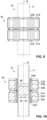
- FIG. 7 and 8 A fourth embodiment of a magnetic bearing device is illustrated in Figures 7 and 8 .
- This embodiment is identical to the third embodiment in Fig. 6 , except that the magnetic guide sleeve 55 has been left away.
- the magnetic guide sleeve 55 can readily be left away because magnetic stray fields will generally be small due to the presence of the magnetic core 31 and the magnetic guide disks 51, 52, and due to the oppositely magnetized permanent magnets 21, 22 and the mirror-symmetric configuration of the stator 30 with respect to a central plane perpendicular to the rotation axis R.
- construction of the magnetic bearing device can be additionally simplified, and cooling can be improved.
- FIG. 9 A fifth embodiment of a magnetic bearing device is illustrated in Figures 9 and 10 .
- two ring-shaped magnetic cores 31A, 31B are present, and a plurality of radial magnetic bearing windings 32A, 32B in toroidal configuration are provided on each of the ring-shaped magnetic cores 31A, 31B.
- Two azimuthally wound, cylindrical axial bearing windings 43A, 43B are provided, each of these axial bearing windings being arranged in the radial gap between the rotor 10 and one set of radial bearing windings 32A, 32B, respectively.
- Only a single permanent magnet 24 is provided.
- the permanent magnet 24 is magnetized along the rotation axis R.
- an optional magnetic guide disk 25, 26 is provided on each axial end of the permanent magnet 24, an optional magnetic guide disk 25, 26 is provided.
- Radial forces are generated in a similar manner as described above for the first embodiment.
- radial bearing windings 32A, 32B arranged on the same ring-shaped magnetic core 31A, 31B, but on diametrically opposite radial sides of the rotor 10 are operated with currents that have the same magnitude, but opposite directions, as in the first embodiment.
- radial bearing windings 32A, 32B arranged on the same radial side of the rotor, but on different ring-shaped magnetic cores 31A, 31B are operated with currents that have the same magnitude, but opposite directions.
- axial forces are generated in a similar manner as described above for the first embodiment, except that currents are supplied to the axial bearing windings 43A, 43B with equal magnitude, but opposite directions.
- the axial bearing windings can also be provided axially adjacent to the radial bearing windings, as in the first embodiment.
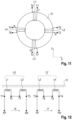
- Fig. 11 illustrates, in a highly schematic manner, an arrangement of four toroidal bearing windings L1, L2, L3, L4 arranged on a common ring-shaped magnetic core 31.
- the terminals of the first bearing winding L1 are designated as T1 and T5; the terminals of the second bearing winding L2 are designated as T2 and T6; the terminals of the third bearing winding L3 are designated as T3 and T7; and the terminals of the fourth bearing winding L4 are designated as T4 and T8.
- Toroidal bearing windings L1 and L3 are arranged on diametrically opposite sides of the rotor along the Y direction, while toroidal bearing windings L2 and L4 are arranged on diametrically opposite sides of the rotor along the X direction.
- Bearing winding L1 is supplied with a current i1, bearing winding L2 with a current i2, bearing winding L3 with a current i3, and bearing winding L4 with a current i4.
- FIG. 12 A connection in anti-series configuration is illustrated in Fig. 12 .
- Bearing windings L1 and L3 are connected in an anti-series configuration to form a winding pair LX, having terminals XP and XN.
- Fig. 13 illustrates, in a highly schematic manner, an amplifier arrangement for driving the winding pairs LX and LY.
- the winding pair LX is connected in a first H-bridge configuration with four semiconductor switches S1, while the winding pair LY is connected in a second H-bridge configuration.
- FIG. 14 illustrates, in a highly schematic manner, an arrangement of six toroidal bearing windings L1, L2, L3, L4, L5, and L6 on a common ring-shaped magnetic core.
- the terminals of the first bearing winding L1 are designated as T1 and T7; the terminals of the second bearing winding L2 are designated as T2 and T8; the terminals of the third bearing winding L3 are designated as T3 and T9; the terminals of the fourth bearing winding L4 are designated as T4 and T10; the terminals of the fifth bearing winding L5 are designated as T5 and T11; and the terminals of the sixth bearing winding L6 are designated as T6 and T12.
- FIG. 15 A convenient way of connecting bearing windings L1 to L6 is illustrated in Fig. 15 . Pairs of bearing windings arranged on diametrically opposite sides of the rotor are connected in an anti-series configuration. The three resulting pairs LU, LV, and LW are connected in a star configuration with a common star point S. The bearing coils can thus be driven by a three-phase current with phases U, V, W in a similar manner as a three-phase motor whose motor windings are connected in a star configuration.
- Fig. 16 shows an alternative arrangement in which the two windings of each pair are connected in an antiparallel configuration, while the pairs are still connected in a star configuration with common star point S.
- the pairs can also be connected in a delta configuration.
- Fig. 18 illustrates an arrangement of only three radial bearing windings LU, LV and LW on a common ring-shaped magnetic core.
- the windings are connected in a star configuration with star point S and can be driven by a three-phase current with phases U, V, W.
- Fig. 19 illustrates a possible amplifier arrangement for driving winding arrangements in a three-phase configuration.
- phase U is driven by a first half-bridge circuit
- phase V is driven by a second half-bridge circuit
- phase W is driven by a third half-bridge circuit.
- This amplifier arrangement can be used for any of the configurations of Figs. 15 to 18 .
Landscapes
- Engineering & Computer Science (AREA)
- General Engineering & Computer Science (AREA)
- Mechanical Engineering (AREA)
- Physics & Mathematics (AREA)
- Electromagnetism (AREA)
- Magnetic Bearings And Hydrostatic Bearings (AREA)
- Connection Of Motors, Electrical Generators, Mechanical Devices, And The Like (AREA)
Claims (14)
- Magnetische Lagervorrichtung, umfassend:einen Stator (30); undeinen Rotor (10), der in dem Stator (30) zur Drehung um eine Drehachse (R) gelagert ist, wobei der Rotor (10) mindestens einen Permanentmagneten (21, 22; 24) umfasst, der entlang der Drehachse (R) magnetisiert ist, undder Stator mindestens einen geschlossenen Magnetkern (31; 31A, 31B), der den Rotor (10) umgibt, und mindestens eine Radiallagerwicklung (32; 32A, 32B) umfasst, die auf dem mindestens einen geschlossenen Magnetkern (31; 31A, 31B) in einer toroidalen Konfiguration angeordnet ist, wobei sich jede Radiallagerwicklung (32; 32A, 32B) um einen geschlossenen Magnetkern (31; 31A, 31B) herum erstreckt, wobei jede ihrer Windungen durch ein zentrales Loch des jeweiligen geschlossenen Magnetkerns (31; 31A, 31B) verläuft,wobei die mindestens eine Radiallagerwicklung (32; 32A, 32B) so angeordnet ist, dass sie mit einer radialen Komponente eines Permanentmagnetfeldes, das von dem mindestens einen Permanentmagneten (21, 22; 24) erzeugt wird, zusammenwirkt, um eine Radiallagerkraft zu erhalten, wenn die mindestens eine Radiallagerwicklung (32; 32A, 32B) mit Strom versorgt wird,dadurch gekennzeichnet, dass der mindestens eine geschlossene Magnetkern (31; 31A, 31B) keine nach innen gerichteten Zähne aufweist.
- Magnetische Lagervorrichtung nach Anspruch 1, ferner umfassend erste und zweite magnetische Führungsringe (51, 52), wobei jeder der ersten und zweiten magnetischen Führungsringe (51, 52) den Rotor (10) umgibt, wobei der erste magnetische Führungsring (51) auf einer ersten axialen Seite der mindestens einen Radiallagerwicklung (32; 32A, 32B) angeordnet ist, und der zweite magnetische Führungsring (52) auf einer zweiten axialen Seite der mindestens einen Radiallagerwicklung (32; 32A, 32B) gegenüber der ersten axialen Seite angeordnet ist, wobei der erste magnetische Führungsring (51) dazu ausgebildet ist, das permanente Magnetfeld zwischen einem ersten axialen Endabschnitt des mindestens einen Permanentmagneten (21, 22; 24) und einem ersten axialen Endabschnitt des geschlossenen Magnetkerns (31; 31A, 31B) zu führen, und der zweite magnetische Führungsring (52) dazu ausgebildet ist, das permanente Magnetfeld zwischen einem zweiten axialen Endabschnitt des mindestens einen Permanentmagneten (21, 22; 24) und einem zweiten axialen Endabschnitt des geschlossenen Magnetkerns (31; 31A, 31B) zu führen.
- Magnetische Lagervorrichtung nach einem der vorhergehenden Ansprüche, wobei der Rotor (10) mindestens eine magnetische Führungsscheibe (23; 25, 26) umfasst, die axial neben dem mindestens einen Permanentmagneten (21, 22; 24) angeordnet ist, wobei die mindestens eine magnetische Führungsscheibe (23; 25, 26) dazu ausgebildet ist, einen magnetischen Fluss, der durch das Permanentmagnetfeld verursacht wird, von der axialen in die radiale Richtung zu konzentrieren und abzulenken und das Permanentmagnetfeld in einem radialen Spaltbereich zwischen dem Rotor (10) und dem geschlossenen Magnetkern (31; 31A, 31B) zu konzentrieren.
- Magnetische Lagervorrichtung nach einem der vorhergehenden Ansprüche, wobei der Rotor einen ersten und einen zweiten Permanentmagneten (21, 22) aufweist, die entlang der Drehachse (R) mit entgegengesetzten Polaritäten magnetisiert sind.
- Magnetische Lagervorrichtung nach Anspruch 4, wobei der Rotor eine magnetische Führungsscheibe (23) umfasst, die axial zwischen dem ersten und zweiten Permanentmagneten (21, 22) angeordnet ist, wobei die magnetische Führungsscheibe (23) dazu ausgebildet ist, das Permanentmagnetfeld in einem radialen Spaltbereich zwischen dem Rotor (10) und dem geschlossenen Magnetkern (31; 31A, 31B) zu konzentrieren.
- Magnetische Lagervorrichtung nach einem der Ansprüche 1 bis 3,wobei der Stator (30) einen ersten und einen zweiten geschlossenen Magnetkern (31A, 31B) umfasst, die den Rotor (10) an verschiedenen axialen Stellen entlang der Drehachse (R) umgeben,wobei der Stator (30) mindestens eine erste Radiallagerwicklung (32A) umfasst, die in einer toroidalen Konfiguration um den ersten geschlossenen Magnetkern (31A) angeordnet ist, und mindestens eine zweite Radiallagerwicklung (32B), die in einer toroidalen Konfiguration um den zweiten geschlossenen Magnetkern (31B) angeordnet ist,wobei die erste und die zweite Radiallagerwicklung (32A, 32B) so angeordnet sind, dass sie mit dem von dem mindestens einen Permanentmagneten (24) erzeugten Permanentmagnetfeld zusammenwirken, um eine Radiallagerkraft zu erhalten, wenn die erste und die zweite Radiallagerwicklung (32A, 32B) mit Strom versorgt werden.
- Magnetische Lagervorrichtung nach Anspruch 6, wobei der mindestens eine Permanentmagnet (24) eine einzige Polarität entlang der Drehachse (R) aufweist.
- Magnetische Lagervorrichtung nach Anspruch 7, wobei der Rotor erste und zweite magnetische Führungsscheiben (25, 26) umfasst, die an axial gegenüberliegenden Enden des mindestens einen Permanentmagneten (24) angeordnet sind, wobei die erste magnetische Führungsscheibe (25) dazu ausgebildet ist, das Permanentmagnetfeld in einem radialen Spaltbereich zwischen dem Rotor (10) und dem ersten geschlossenen Magnetkern (31A) zu konzentrieren, und die zweite magnetische Führungsscheibe (26) dazu ausgebildet ist, das Permanentmagnetfeld in einem radialen Spaltbereich zwischen dem Rotor (10) und dem zweiten geschlossenen Magnetkern (31B) zu konzentrieren.
- Magnetische Lagervorrichtung nach einem der vorhergehenden Ansprüche, die ferner mindestens eine Axiallagerwicklung (41, 42; 43) umfasst, die azimutal um den Rotor (10) gewickelt ist, wobei die mindestens eine Axiallagerwicklung (41, 42; 43; 43A, 43B) so angeordnet ist, dass sie mit dem von dem mindestens einen Permanentmagneten (21, 22; 24) erzeugten Permanentmagnetfeld zusammenwirkt, um eine Axiallagerkraft zu erhalten, wenn die mindestens eine Axiallagerwicklung (41, 42; 43; 43A, 43B) mit Strom versorgt wird.
- Magnetische Lagervorrichtung nach Anspruch 9, mit zwei Axiallagerwicklungen (41, 42), die auf axial gegenüberliegenden Seiten der mindestens einen Radiallagerwicklung (32; 32A, 32B) angeordnet sind.
- Magnetische Lagervorrichtung nach Anspruch 9 oder 10, mit mindestens einer Axiallagerwicklung (43; 43A, 43B), die in einem radialen Spalt zwischen dem Rotor (10) und dem geschlossenen Magnetkern (31; 31A, 31B), insbesondere zwischen dem Rotor (10) und der mindestens einen Radiallagerwicklung (32; 32A, 32B), angeordnet ist.
- Magnetische Lagervorrichtung nach einem der vorangehenden Ansprüche, ferner umfassend:mindestens einen Radialverschiebungssensor (61) zur Erfassung von Radialverschiebungen des Rotors (10); undeine Steuerung (70), die dazu ausgebildet ist, Signale von dem mindestens einen Radialverschiebungssensor (61) zu empfangen und Radialsteuersignale für die mindestens eine Radiallagerwicklung (32; 32A, 32B) zu erzeugen, um eine radiale Position des Rotors (10) zu beeinflussen.
- Magnetische Lagervorrichtung nach Anspruch 12, ferner umfassend:mindestens einen Axialverschiebungssensor (62) zur Erfassung von Axialverschiebungen des Rotors (10),wobei die Steuerung (70) ferner dazu ausgebildet ist, Signale von dem mindestens einen axialen Verschiebungssensor (62) zu empfangen und Axialsteuersignale für mindestens eine Axiallagerwicklung (41, 42; 43; 43A, 43B) zu erzeugen, um eine axiale Position des Rotors (10) zu beeinflussen.
- Magnetische Lagervorrichtung nach einem der vorhergehenden Ansprüche,umfassend mindestens ein Paar Radiallagerwicklungen (32; 32A, 32B), die auf diametral gegenüberliegenden Seiten des Rotors (10) in toroidaler Anordnung auf einem gemeinsamen geschlossenen Magnetkern (31; 31A, 31B) angeordnet und antireihen- oder antiparallel geschaltet sind, und/oderumfassend mindestens drei Radiallagerwicklungen (32; 32A, 32B), die auf einem gemeinsamen geschlossenen Magnetkern (31; 31A, 31B) in Ringform verteilt und in Stern- oder Dreieckform geschaltet sind.
Priority Applications (6)
| Application Number | Priority Date | Filing Date | Title |
|---|---|---|---|
| EP19195639.0A EP3789624B1 (de) | 2019-09-05 | 2019-09-05 | Magnetische lagervorrichtung mit einem toroidalen design |
| US17/597,445 US20220163065A1 (en) | 2019-09-05 | 2020-08-24 | Magnetic bearing device having a toroidal design |
| CN202080059186.1A CN114270059A (zh) | 2019-09-05 | 2020-08-24 | 具有环形设计的磁性轴承装置 |
| PCT/EP2020/073591 WO2021043607A1 (en) | 2019-09-05 | 2020-08-24 | Magnetic bearing device having a toroidal design |
| JP2022505255A JP2022547387A (ja) | 2019-09-05 | 2020-08-24 | トロイダル設計を有する磁気軸受装置 |
| KR1020227011000A KR20220053667A (ko) | 2019-09-05 | 2020-08-24 | 토로이달 디자인을 가지는 자기 베어링 디바이스 |
Applications Claiming Priority (1)
| Application Number | Priority Date | Filing Date | Title |
|---|---|---|---|
| EP19195639.0A EP3789624B1 (de) | 2019-09-05 | 2019-09-05 | Magnetische lagervorrichtung mit einem toroidalen design |
Publications (2)
| Publication Number | Publication Date |
|---|---|
| EP3789624A1 EP3789624A1 (de) | 2021-03-10 |
| EP3789624B1 true EP3789624B1 (de) | 2023-06-28 |
Family
ID=67874353
Family Applications (1)
| Application Number | Title | Priority Date | Filing Date |
|---|---|---|---|
| EP19195639.0A Active EP3789624B1 (de) | 2019-09-05 | 2019-09-05 | Magnetische lagervorrichtung mit einem toroidalen design |
Country Status (6)
| Country | Link |
|---|---|
| US (1) | US20220163065A1 (de) |
| EP (1) | EP3789624B1 (de) |
| JP (1) | JP2022547387A (de) |
| KR (1) | KR20220053667A (de) |
| CN (1) | CN114270059A (de) |
| WO (1) | WO2021043607A1 (de) |
Family Cites Families (19)
| Publication number | Priority date | Publication date | Assignee | Title |
|---|---|---|---|---|
| DE2213465C3 (de) * | 1972-03-20 | 1986-02-13 | Padana AG, Zug | Elektromagnetisches Lagerelement |
| DE2420814C3 (de) * | 1974-04-30 | 1980-10-16 | Padana Ag, Zug (Schweiz) | Magnetlager mit einem Lagerelement zur Festlegung eines translatorischen Freiheitsgrades |
| DE2537597A1 (de) * | 1975-08-23 | 1977-03-03 | Padana Ag | Elektromagnetische lagerungseinrichtung |
| DE59712591D1 (de) * | 1997-08-25 | 2006-05-04 | Levitronix Llc | Magnetgelagerte Rotationsanordnung |
| JP3636939B2 (ja) * | 1999-07-15 | 2005-04-06 | オークマ株式会社 | 磁気軸受の制御装置 |
| JP2002257136A (ja) * | 2001-02-27 | 2002-09-11 | Koyo Seiko Co Ltd | 磁気軸受 |
| EP1679492A1 (de) * | 2005-01-11 | 2006-07-12 | Mecos Traxler AG | Wirbelstromsensor und Magnetlagervorrichtung |
| ATE421647T1 (de) * | 2005-08-24 | 2009-02-15 | Mecos Traxler Ag | Rotorwelle für eine magnetlagereinrichtung |
| US7557480B2 (en) * | 2007-04-05 | 2009-07-07 | Calnetix, Inc. | Communicating magnetic flux across a gap with a rotating body |
| JP5120053B2 (ja) * | 2008-05-01 | 2013-01-16 | 株式会社明電舎 | 磁気軸受装置 |
| US8378543B2 (en) * | 2009-11-02 | 2013-02-19 | Calnetix Technologies, L.L.C. | Generating electromagnetic forces in large air gaps |
| US20150137647A1 (en) * | 2012-03-20 | 2015-05-21 | Linear Labs, Inc. | Brushless electric motor/generator |
| WO2016137775A1 (en) * | 2015-02-26 | 2016-09-01 | Carrier Corporation | Magnetic bearing |
| EP3232549B1 (de) * | 2016-04-14 | 2020-12-16 | Levitronix GmbH | Elektromagnetischer drehantrieb und rotationsvorrichtung |
| FI128371B (en) * | 2016-08-24 | 2020-04-15 | Lappeenrannan Teknillinen Yliopisto | Stator module for axial magnetic bearing |
| JP6781345B2 (ja) * | 2016-11-17 | 2020-11-04 | ベイカー ヒューズ ホールディングス エルエルシー | シャフトの低速回転制御のためのスラスト能動型磁気軸受 |
| ES2897273T3 (es) * | 2017-04-01 | 2022-02-28 | Carrier Corp | Rodamiento magnético radial con refuerzo de flujo |
| EP3431789B1 (de) * | 2017-07-20 | 2019-11-20 | Mecos AG | Streuflussausgleich in einer magnetlagervorrichtung |
| EP3450782B1 (de) * | 2017-09-05 | 2019-11-06 | Lakeview Innovation Ltd. | Aktives radiales magnetlager mit jochwicklung |
-
2019
- 2019-09-05 EP EP19195639.0A patent/EP3789624B1/de active Active
-
2020
- 2020-08-24 CN CN202080059186.1A patent/CN114270059A/zh active Pending
- 2020-08-24 JP JP2022505255A patent/JP2022547387A/ja active Pending
- 2020-08-24 KR KR1020227011000A patent/KR20220053667A/ko not_active Ceased
- 2020-08-24 WO PCT/EP2020/073591 patent/WO2021043607A1/en not_active Ceased
- 2020-08-24 US US17/597,445 patent/US20220163065A1/en not_active Abandoned
Also Published As
| Publication number | Publication date |
|---|---|
| KR20220053667A (ko) | 2022-04-29 |
| WO2021043607A1 (en) | 2021-03-11 |
| CN114270059A (zh) | 2022-04-01 |
| EP3789624A1 (de) | 2021-03-10 |
| JP2022547387A (ja) | 2022-11-14 |
| US20220163065A1 (en) | 2022-05-26 |
Similar Documents
| Publication | Publication Date | Title |
|---|---|---|
| US11784529B2 (en) | Torque tunnel Halbach Array electric machine | |
| JP6193456B1 (ja) | 同期電動機 | |
| US4918345A (en) | Magnetic bearing for active centering of a body movable relative to a static body with respect to at least one axis | |
| US6175178B1 (en) | Low inductance electrical machine for flywheel energy storage | |
| US6727617B2 (en) | Method and apparatus for providing three axis magnetic bearing having permanent magnets mounted on radial pole stack | |
| CN111279586B (zh) | 一种电动机 | |
| JP5956993B2 (ja) | リニアモータ | |
| CN107257889B (zh) | 磁轴承 | |
| TWI425746B (zh) | 線性馬達 | |
| JP2005527176A (ja) | 複数の斜め固定子極及び/又は回転子極を有する回転式電気モーター | |
| JP2002354767A (ja) | 磁気浮上電動機 | |
| WO2010027740A1 (en) | Linear motor with patterned magnet arrays | |
| JPH01194854A (ja) | リニアモータ | |
| JP2002505066A (ja) | 磁気軸支電気駆動装置 | |
| US20200067380A1 (en) | Electric machine having an axial electrodynamic bearing | |
| EP3789624B1 (de) | Magnetische lagervorrichtung mit einem toroidalen design | |
| US20220166302A1 (en) | Bipolar linear step motor | |
| JP2013137067A (ja) | 磁気軸受 | |
| EP4082095B1 (de) | Elektronische motoren und verfahren zur steuerung davon | |
| JP2007009949A (ja) | ハイブリッド型磁気軸受 | |
| JP6990014B2 (ja) | 回転電機 | |
| GB2380618A (en) | Electric rotating machine with magnetic bearing | |
| JP2005520470A (ja) | モーター/交流発電機/同期発電機万能機器 | |
| JP6631102B2 (ja) | 回転電機 | |
| WO2003032470A1 (en) | Electrical machine having capability to generate lateral forces |
Legal Events
| Date | Code | Title | Description |
|---|---|---|---|
| PUAI | Public reference made under article 153(3) epc to a published international application that has entered the european phase |
Free format text: ORIGINAL CODE: 0009012 |
|
| STAA | Information on the status of an ep patent application or granted ep patent |
Free format text: STATUS: THE APPLICATION HAS BEEN PUBLISHED |
|
| AK | Designated contracting states |
Kind code of ref document: A1 Designated state(s): AL AT BE BG CH CY CZ DE DK EE ES FI FR GB GR HR HU IE IS IT LI LT LU LV MC MK MT NL NO PL PT RO RS SE SI SK SM TR |
|
| AX | Request for extension of the european patent |
Extension state: BA ME |
|
| STAA | Information on the status of an ep patent application or granted ep patent |
Free format text: STATUS: REQUEST FOR EXAMINATION WAS MADE |
|
| 17P | Request for examination filed |
Effective date: 20210817 |
|
| RBV | Designated contracting states (corrected) |
Designated state(s): AL AT BE BG CH CY CZ DE DK EE ES FI FR GB GR HR HU IE IS IT LI LT LU LV MC MK MT NL NO PL PT RO RS SE SI SK SM TR |
|
| STAA | Information on the status of an ep patent application or granted ep patent |
Free format text: STATUS: EXAMINATION IS IN PROGRESS |
|
| 17Q | First examination report despatched |
Effective date: 20220131 |
|
| GRAP | Despatch of communication of intention to grant a patent |
Free format text: ORIGINAL CODE: EPIDOSNIGR1 |
|
| STAA | Information on the status of an ep patent application or granted ep patent |
Free format text: STATUS: GRANT OF PATENT IS INTENDED |
|
| GRAJ | Information related to disapproval of communication of intention to grant by the applicant or resumption of examination proceedings by the epo deleted |
Free format text: ORIGINAL CODE: EPIDOSDIGR1 |
|
| STAA | Information on the status of an ep patent application or granted ep patent |
Free format text: STATUS: EXAMINATION IS IN PROGRESS |
|
| INTG | Intention to grant announced |
Effective date: 20221124 |
|
| INTC | Intention to grant announced (deleted) | ||
| GRAJ | Information related to disapproval of communication of intention to grant by the applicant or resumption of examination proceedings by the epo deleted |
Free format text: ORIGINAL CODE: EPIDOSDIGR1 |
|
| GRAP | Despatch of communication of intention to grant a patent |
Free format text: ORIGINAL CODE: EPIDOSNIGR1 |
|
| GRAP | Despatch of communication of intention to grant a patent |
Free format text: ORIGINAL CODE: EPIDOSNIGR1 |
|
| STAA | Information on the status of an ep patent application or granted ep patent |
Free format text: STATUS: GRANT OF PATENT IS INTENDED |
|
| INTG | Intention to grant announced |
Effective date: 20230125 |
|
| GRAS | Grant fee paid |
Free format text: ORIGINAL CODE: EPIDOSNIGR3 |
|
| GRAA | (expected) grant |
Free format text: ORIGINAL CODE: 0009210 |
|
| STAA | Information on the status of an ep patent application or granted ep patent |
Free format text: STATUS: THE PATENT HAS BEEN GRANTED |
|
| AK | Designated contracting states |
Kind code of ref document: B1 Designated state(s): AL AT BE BG CH CY CZ DE DK EE ES FI FR GB GR HR HU IE IS IT LI LT LU LV MC MK MT NL NO PL PT RO RS SE SI SK SM TR |
|
| REG | Reference to a national code |
Ref country code: CH Ref legal event code: EP |
|
| REG | Reference to a national code |
Ref country code: AT Ref legal event code: REF Ref document number: 1582925 Country of ref document: AT Kind code of ref document: T Effective date: 20230715 |
|
| REG | Reference to a national code |
Ref country code: IE Ref legal event code: FG4D |
|
| REG | Reference to a national code |
Ref country code: DE Ref legal event code: R096 Ref document number: 602019031604 Country of ref document: DE |
|
| REG | Reference to a national code |
Ref country code: LT Ref legal event code: MG9D |
|
| PG25 | Lapsed in a contracting state [announced via postgrant information from national office to epo] |
Ref country code: SE Free format text: LAPSE BECAUSE OF FAILURE TO SUBMIT A TRANSLATION OF THE DESCRIPTION OR TO PAY THE FEE WITHIN THE PRESCRIBED TIME-LIMIT Effective date: 20230628 Ref country code: NO Free format text: LAPSE BECAUSE OF FAILURE TO SUBMIT A TRANSLATION OF THE DESCRIPTION OR TO PAY THE FEE WITHIN THE PRESCRIBED TIME-LIMIT Effective date: 20230928 |
|
| REG | Reference to a national code |
Ref country code: NL Ref legal event code: MP Effective date: 20230628 |
|
| REG | Reference to a national code |
Ref country code: AT Ref legal event code: MK05 Ref document number: 1582925 Country of ref document: AT Kind code of ref document: T Effective date: 20230628 |
|
| PG25 | Lapsed in a contracting state [announced via postgrant information from national office to epo] |
Ref country code: RS Free format text: LAPSE BECAUSE OF FAILURE TO SUBMIT A TRANSLATION OF THE DESCRIPTION OR TO PAY THE FEE WITHIN THE PRESCRIBED TIME-LIMIT Effective date: 20230628 Ref country code: NL Free format text: LAPSE BECAUSE OF FAILURE TO SUBMIT A TRANSLATION OF THE DESCRIPTION OR TO PAY THE FEE WITHIN THE PRESCRIBED TIME-LIMIT Effective date: 20230628 Ref country code: LV Free format text: LAPSE BECAUSE OF FAILURE TO SUBMIT A TRANSLATION OF THE DESCRIPTION OR TO PAY THE FEE WITHIN THE PRESCRIBED TIME-LIMIT Effective date: 20230628 Ref country code: LT Free format text: LAPSE BECAUSE OF FAILURE TO SUBMIT A TRANSLATION OF THE DESCRIPTION OR TO PAY THE FEE WITHIN THE PRESCRIBED TIME-LIMIT Effective date: 20230628 Ref country code: HR Free format text: LAPSE BECAUSE OF FAILURE TO SUBMIT A TRANSLATION OF THE DESCRIPTION OR TO PAY THE FEE WITHIN THE PRESCRIBED TIME-LIMIT Effective date: 20230628 Ref country code: GR Free format text: LAPSE BECAUSE OF FAILURE TO SUBMIT A TRANSLATION OF THE DESCRIPTION OR TO PAY THE FEE WITHIN THE PRESCRIBED TIME-LIMIT Effective date: 20230929 |
|
| PG25 | Lapsed in a contracting state [announced via postgrant information from national office to epo] |
Ref country code: FI Free format text: LAPSE BECAUSE OF FAILURE TO SUBMIT A TRANSLATION OF THE DESCRIPTION OR TO PAY THE FEE WITHIN THE PRESCRIBED TIME-LIMIT Effective date: 20230628 |
|
| PG25 | Lapsed in a contracting state [announced via postgrant information from national office to epo] |
Ref country code: SK Free format text: LAPSE BECAUSE OF FAILURE TO SUBMIT A TRANSLATION OF THE DESCRIPTION OR TO PAY THE FEE WITHIN THE PRESCRIBED TIME-LIMIT Effective date: 20230628 |
|
| PG25 | Lapsed in a contracting state [announced via postgrant information from national office to epo] |
Ref country code: ES Free format text: LAPSE BECAUSE OF FAILURE TO SUBMIT A TRANSLATION OF THE DESCRIPTION OR TO PAY THE FEE WITHIN THE PRESCRIBED TIME-LIMIT Effective date: 20230628 |
|
| PG25 | Lapsed in a contracting state [announced via postgrant information from national office to epo] |
Ref country code: IS Free format text: LAPSE BECAUSE OF FAILURE TO SUBMIT A TRANSLATION OF THE DESCRIPTION OR TO PAY THE FEE WITHIN THE PRESCRIBED TIME-LIMIT Effective date: 20231028 |
|
| PG25 | Lapsed in a contracting state [announced via postgrant information from national office to epo] |
Ref country code: SM Free format text: LAPSE BECAUSE OF FAILURE TO SUBMIT A TRANSLATION OF THE DESCRIPTION OR TO PAY THE FEE WITHIN THE PRESCRIBED TIME-LIMIT Effective date: 20230628 Ref country code: SK Free format text: LAPSE BECAUSE OF FAILURE TO SUBMIT A TRANSLATION OF THE DESCRIPTION OR TO PAY THE FEE WITHIN THE PRESCRIBED TIME-LIMIT Effective date: 20230628 Ref country code: RO Free format text: LAPSE BECAUSE OF FAILURE TO SUBMIT A TRANSLATION OF THE DESCRIPTION OR TO PAY THE FEE WITHIN THE PRESCRIBED TIME-LIMIT Effective date: 20230628 Ref country code: PT Free format text: LAPSE BECAUSE OF FAILURE TO SUBMIT A TRANSLATION OF THE DESCRIPTION OR TO PAY THE FEE WITHIN THE PRESCRIBED TIME-LIMIT Effective date: 20231030 Ref country code: IS Free format text: LAPSE BECAUSE OF FAILURE TO SUBMIT A TRANSLATION OF THE DESCRIPTION OR TO PAY THE FEE WITHIN THE PRESCRIBED TIME-LIMIT Effective date: 20231028 Ref country code: ES Free format text: LAPSE BECAUSE OF FAILURE TO SUBMIT A TRANSLATION OF THE DESCRIPTION OR TO PAY THE FEE WITHIN THE PRESCRIBED TIME-LIMIT Effective date: 20230628 Ref country code: EE Free format text: LAPSE BECAUSE OF FAILURE TO SUBMIT A TRANSLATION OF THE DESCRIPTION OR TO PAY THE FEE WITHIN THE PRESCRIBED TIME-LIMIT Effective date: 20230628 Ref country code: CZ Free format text: LAPSE BECAUSE OF FAILURE TO SUBMIT A TRANSLATION OF THE DESCRIPTION OR TO PAY THE FEE WITHIN THE PRESCRIBED TIME-LIMIT Effective date: 20230628 Ref country code: AT Free format text: LAPSE BECAUSE OF FAILURE TO SUBMIT A TRANSLATION OF THE DESCRIPTION OR TO PAY THE FEE WITHIN THE PRESCRIBED TIME-LIMIT Effective date: 20230628 |
|
| PG25 | Lapsed in a contracting state [announced via postgrant information from national office to epo] |
Ref country code: PL Free format text: LAPSE BECAUSE OF FAILURE TO SUBMIT A TRANSLATION OF THE DESCRIPTION OR TO PAY THE FEE WITHIN THE PRESCRIBED TIME-LIMIT Effective date: 20230628 |
|
| REG | Reference to a national code |
Ref country code: DE Ref legal event code: R097 Ref document number: 602019031604 Country of ref document: DE |
|
| PG25 | Lapsed in a contracting state [announced via postgrant information from national office to epo] |
Ref country code: DK Free format text: LAPSE BECAUSE OF FAILURE TO SUBMIT A TRANSLATION OF THE DESCRIPTION OR TO PAY THE FEE WITHIN THE PRESCRIBED TIME-LIMIT Effective date: 20230628 |
|
| PLBE | No opposition filed within time limit |
Free format text: ORIGINAL CODE: 0009261 |
|
| STAA | Information on the status of an ep patent application or granted ep patent |
Free format text: STATUS: NO OPPOSITION FILED WITHIN TIME LIMIT |
|
| PG25 | Lapsed in a contracting state [announced via postgrant information from national office to epo] |
Ref country code: LU Free format text: LAPSE BECAUSE OF NON-PAYMENT OF DUE FEES Effective date: 20230905 |
|
| REG | Reference to a national code |
Ref country code: BE Ref legal event code: MM Effective date: 20230930 |
|
| GBPC | Gb: european patent ceased through non-payment of renewal fee |
Effective date: 20230928 |
|
| PG25 | Lapsed in a contracting state [announced via postgrant information from national office to epo] |
Ref country code: IT Free format text: LAPSE BECAUSE OF FAILURE TO SUBMIT A TRANSLATION OF THE DESCRIPTION OR TO PAY THE FEE WITHIN THE PRESCRIBED TIME-LIMIT Effective date: 20230628 Ref country code: LU Free format text: LAPSE BECAUSE OF NON-PAYMENT OF DUE FEES Effective date: 20230905 Ref country code: MC Free format text: LAPSE BECAUSE OF FAILURE TO SUBMIT A TRANSLATION OF THE DESCRIPTION OR TO PAY THE FEE WITHIN THE PRESCRIBED TIME-LIMIT Effective date: 20230628 |
|
| 26N | No opposition filed |
Effective date: 20240402 |
|
| REG | Reference to a national code |
Ref country code: IE Ref legal event code: MM4A |
|
| PG25 | Lapsed in a contracting state [announced via postgrant information from national office to epo] |
Ref country code: IE Free format text: LAPSE BECAUSE OF NON-PAYMENT OF DUE FEES Effective date: 20230905 |
|
| PG25 | Lapsed in a contracting state [announced via postgrant information from national office to epo] |
Ref country code: GB Free format text: LAPSE BECAUSE OF NON-PAYMENT OF DUE FEES Effective date: 20230928 |
|
| PG25 | Lapsed in a contracting state [announced via postgrant information from national office to epo] |
Ref country code: IE Free format text: LAPSE BECAUSE OF NON-PAYMENT OF DUE FEES Effective date: 20230905 Ref country code: GB Free format text: LAPSE BECAUSE OF NON-PAYMENT OF DUE FEES Effective date: 20230928 Ref country code: SI Free format text: LAPSE BECAUSE OF FAILURE TO SUBMIT A TRANSLATION OF THE DESCRIPTION OR TO PAY THE FEE WITHIN THE PRESCRIBED TIME-LIMIT Effective date: 20230628 |
|
| PG25 | Lapsed in a contracting state [announced via postgrant information from national office to epo] |
Ref country code: BE Free format text: LAPSE BECAUSE OF NON-PAYMENT OF DUE FEES Effective date: 20230930 |
|
| PG25 | Lapsed in a contracting state [announced via postgrant information from national office to epo] |
Ref country code: BG Free format text: LAPSE BECAUSE OF FAILURE TO SUBMIT A TRANSLATION OF THE DESCRIPTION OR TO PAY THE FEE WITHIN THE PRESCRIBED TIME-LIMIT Effective date: 20230628 |
|
| PG25 | Lapsed in a contracting state [announced via postgrant information from national office to epo] |
Ref country code: BG Free format text: LAPSE BECAUSE OF FAILURE TO SUBMIT A TRANSLATION OF THE DESCRIPTION OR TO PAY THE FEE WITHIN THE PRESCRIBED TIME-LIMIT Effective date: 20230628 |
|
| PG25 | Lapsed in a contracting state [announced via postgrant information from national office to epo] |
Ref country code: CY Free format text: LAPSE BECAUSE OF FAILURE TO SUBMIT A TRANSLATION OF THE DESCRIPTION OR TO PAY THE FEE WITHIN THE PRESCRIBED TIME-LIMIT; INVALID AB INITIO Effective date: 20190905 |
|
| PG25 | Lapsed in a contracting state [announced via postgrant information from national office to epo] |
Ref country code: HU Free format text: LAPSE BECAUSE OF FAILURE TO SUBMIT A TRANSLATION OF THE DESCRIPTION OR TO PAY THE FEE WITHIN THE PRESCRIBED TIME-LIMIT; INVALID AB INITIO Effective date: 20190905 |
|
| REG | Reference to a national code |
Ref country code: CH Ref legal event code: U11 Free format text: ST27 STATUS EVENT CODE: U-0-0-U10-U11 (AS PROVIDED BY THE NATIONAL OFFICE) Effective date: 20251001 |
|
| PGFP | Annual fee paid to national office [announced via postgrant information from national office to epo] |
Ref country code: DE Payment date: 20250919 Year of fee payment: 7 |
|
| PGFP | Annual fee paid to national office [announced via postgrant information from national office to epo] |
Ref country code: FR Payment date: 20250922 Year of fee payment: 7 |
|
| PG25 | Lapsed in a contracting state [announced via postgrant information from national office to epo] |
Ref country code: TR Free format text: LAPSE BECAUSE OF FAILURE TO SUBMIT A TRANSLATION OF THE DESCRIPTION OR TO PAY THE FEE WITHIN THE PRESCRIBED TIME-LIMIT Effective date: 20230628 |
|
| PGFP | Annual fee paid to national office [announced via postgrant information from national office to epo] |
Ref country code: CH Payment date: 20251001 Year of fee payment: 7 |