EP3789679A1 - Kombinationsgerät mit dunstabzugsvorrichtung und kochfeld - Google Patents
Kombinationsgerät mit dunstabzugsvorrichtung und kochfeld Download PDFInfo
- Publication number
- EP3789679A1 EP3789679A1 EP20190681.5A EP20190681A EP3789679A1 EP 3789679 A1 EP3789679 A1 EP 3789679A1 EP 20190681 A EP20190681 A EP 20190681A EP 3789679 A1 EP3789679 A1 EP 3789679A1
- Authority
- EP
- European Patent Office
- Prior art keywords
- cover plate
- protective grille
- combination device
- positioning frame
- recess
- Prior art date
- Legal status (The legal status is an assumption and is not a legal conclusion. Google has not performed a legal analysis and makes no representation as to the accuracy of the status listed.)
- Granted
Links
Images




Classifications
-
- F—MECHANICAL ENGINEERING; LIGHTING; HEATING; WEAPONS; BLASTING
- F24—HEATING; RANGES; VENTILATING
- F24C—DOMESTIC STOVES OR RANGES ; DETAILS OF DOMESTIC STOVES OR RANGES, OF GENERAL APPLICATION
- F24C15/00—Details
- F24C15/20—Removing cooking fumes
- F24C15/2042—Devices for removing cooking fumes structurally associated with a cooking range e.g. downdraft
Definitions
- the present invention relates to a combination device with an extractor device and a hob.
- combination devices consisting of an extractor device and a hob, which are also referred to as venting cooktop, are used in kitchens.
- the extractor device is arranged below the hob in the combination device.
- a recess is made in the hob and in particular in the cover plate of the hob, through which air can be sucked down to the extractor device.
- a protective grille is preferably attached to the recess. This can in particular be placed on the recess.
- a disadvantage of this arrangement of the protective grille is that the visual appearance of the hob is impaired by the upward protrusion of the protective grille.
- Another disadvantage is that the displacement of cooking vessels on the hob is hindered by the protective grille protruding upwards over the cover plate.
- the invention is therefore achieved by a combination device comprising a hob with a cover plate and an extractor device.
- the combination device is characterized in that the combination device has a protective grille and a positioning frame for positioning the protective grille in a recess in the cover plate, which is attached to the cover plate and is in contact with the protective grille.
- Directional information such as above and below as well as front and rear, unless otherwise stated, relate to the combination device and its components in an installed state in which the hob is horizontal.
- the front side is the side facing the user.
- the back is the side that usually faces a mounting wall.
- the dimension in the direction between the front and the back is called the depth.
- the horizontal dimension perpendicular to this is called the width.
- the vertical dimension is called the height.
- the hob has a cover plate.
- the hob preferably has at least one cooking module which is arranged on the underside of the cover plate.
- the extractor device of the combination device preferably comprises a fan and a filter unit.
- the filter unit is preferably arranged in the combination device in such a way that it is arranged below the recess in the cover plate in order to be able to free contaminants from contaminated air that enters the combination device through the recess.
- the recess in the cover plate is preferably provided in the middle of the width of the cover plate.
- the recess preferably extends in the depth direction of the cover plate and represents a rectangular recess.
- the invention is described below essentially with reference to this embodiment. However, the invention is not restricted to this embodiment. Rather, the recess can, for example, also be made at the edge of the cover plate and / or have a round cross section or extend in the width direction of the cover plate.
- the protective grille which is provided according to the invention, can represent a flat grille.
- the protective grille preferably has a frame which extends in the vertical direction of the combination device.
- the grid formed in the top of the frame can be a flat grid.
- the combination device has a positioning frame.
- the positioning frame preferably has a shape that corresponds to the shape of the recess in the cover plate. In the case of a rectangular recess with rounded corners, the positioning frame therefore also has a rectangular shape with rounded corners.
- the positioning frame is used to position the protective grille in the recess in the cover plate.
- the positioning frame is attached to the cover plate and is in contact with the protective grille.
- the position of the protective grille with respect to the recess is determined by the positioning frame.
- the protective grille which is aligned and preferably held in the recess by the positioning frame, can be introduced into the recess without the need to protrude over the top of the cover plate for the protective grille to rest on the cover plate.
- the provision of the positioning frame shortens the tolerance chain that determines the mutual alignment of the protective grille and the recess.
- the mutual alignment of the recess and the protective grille is determined by a large number of tolerances of components in between. In the present invention, however, this tolerance chain is limited to the recess, the grid and the positioning frame.
- the protective grille lies in the recess of the cover plate and the upper edge of the protective grille lies flush with the top of the cover plate or the upper edge of the protective grille lies below the upper edge of the cover plate.
- the protective grille is possible with the combination device according to the invention, since this is aligned and preferably held with respect to the recess by the positioning frame.
- the positioning frame is attached to the underside of the cover plate around the recess. Since the positioning frame is attached to the underside, it is not visible to the user and the visual appearance of the combination device is therefore improved.
- the positioning frame can also serve as protection against the ingress of liquid.
- the positioning frame in this arrangement can prevent liquids from entering the sides of the recess below the cover plate. Since, for example, the cooking modules of the hob can be arranged in this area, such a barrier against the entry of liquid, which is created by the positioning frame, is advantageous for the safety of the operation of the combination device.
- the positioning frame has an inner circumference that is smaller than the outer circumference of the protective grille on the top of the protective grille.
- the shape of the positioning frame is adapted to the outer shape of the protective grille.
- the positioning frame can have an elongated, rectangular shape. Since the inner circumference of the positioning frame is smaller than the outer circumference of the protective grille on the upper side of the protective grille, the positioning frame can come into contact with the protective grille from below and thereby support the protective grille.
- the inner circumference of the positioning frame preferably corresponds to the outer circumference of the protective grille in an area of the protective grille that is below the top. In this way, lateral support of the protective grille can be ensured by the positioning frame.
- the positioning frame has at least one projection which extends inward from the inner circumference of the positioning frame.
- the positioning frame comprises a support frame and a sealing ring which is held on the underside of the support frame.
- a rigid component is referred to as a carrier frame, which is used in particular to align and hold the protective grille.
- the combination device therefore has a filter housing which is arranged under the recess and the sealing ring rests on the top of the filter housing.
- the positioning frame is attached to the cover plate by means of a pre-fixing and an adhesive connection.
- a pre-fixing and an adhesive connection For pre-fixing, double-sided adhesive strips, for example, can be used on the top of the positioning frame. Silicone can be used for the adhesive connection.
- the positioning frame ensures correct alignment and centering between the protective grille and the recess, which serves as the suction opening of the extractor device.
- Figure 1 is a perspective top view of an embodiment of a combination device 1 according to the invention.
- the combination device 1 is installed in a worktop and only the hob 2 of the combination device 1 is visible.
- the cover plate 20 of the hob 2 with the recess 200 made therein is visible.
- Part of the filter unit 3 can be seen below the recess 200.
- the Figure 3 shows how, in an embodiment without a positioning ring and possibly an incorrectly aligned protective grille 31, liquid can get into the interior of the combination device 1.
- the arrows R indicate the course of liquid which enters the recess 200 and thus the combination device 1 on the correct path.
- the liquid reaches the filter elements of the filter unit 3, which is located below the recess 200.
- the arrows F indicate how liquid can inadvertently enter the space between the cover plate 20 and, for example, a hob housing if the liquid running sideways between the top of the filter unit 3 and the protective grille is not covered.
- FIG 4 an embodiment of the combination device 1 according to the invention is shown before it is installed in a worktop.
- the device housing 10 of the combination device 1 is visible.
- the cover plate 20 of the hob 2 is placed on the device housing 10.
- the protective grille 31 is introduced into the recess 200.
- a positioning frame 5 is attached to the underside of the cover plate 20.
- the positioning frame 5 extends around the recess 200 on the underside of the cover plate 20.
- the inner circumference of the positioning frame 5 is preferably aligned with the inner circumference of the recess 200.
- the attachment of the positioning frame 5 to the cover plate 20 is in the Figures 6 and 7 shown schematically.
- the positioning frame 5 can in particular by means of adhesive strips 52 (see Figure 10 ), which are applied to the top of tabs of the positioning frame 5 can be fixed to the cover plate 20.
- an adhesive sealant for example silicone, is applied to the top of the positioning frame 5, in particular to the top of the support frame 50 (see FIG. Figure 11 ).
- the function of the adhesive strips 52 is therefore to prevent movements between the positioning frame 5 and the cover plate 20 while the silicone is hardening.
- the adhesive strips therefore serve to pre-fix the positioning frame 5 on the cover plate 20.
- the positioning of the center point of the positioning frame 5 and the recess 200 must be as precise as possible. A deviation of a maximum of a few tenths of a millimeter can be achieved.
- the positioning frame 5 is attached to the cover plate 20, the cover plate 20 can be placed on the hob. As in Figures 8 and 12th can be seen, the positioning frame 5 is inside the combination device 1 and is not visible to the user.
- the positioning ring 5 surrounds the edge of the protective grille 31, in particular a flange of the protective grille 31, which extends downward.
- the positioning frame 5 preferably also has at least one contact projection 500 (see FIG Figure 9 ), which extends from the inner circumference of the positioning frame 5 inward.
- the contact protrusions 500 prevent the protective grille 31 from sliding to the left or right edge of the recess 200 and thus maintain the correct distances A and B between the inner edge of the recess 200 and the outer edge of the protective grille 31.
- the positioning frame 5 in the embodiment shown consists of several parts.
- the positioning frame 5 has a carrier frame 50, which can be made of plastic, a sealing ring 51, which can be made of foam, and adhesive strips 52.
- the sealing ring 51 points downwards.
- a filter housing 30 of the filter unit 3 of the combination device 1 is arranged below the recess 200.
- the sealing ring 51 is compressed between the cover plate 20 and the filter housing 30 and seals the distance between these parts.
- the positioning of the protective grille - recess does not depend on the other inner parts of the combination device, such as a frame, inner housing and the like, which can add up to a tolerance of several millimeters.
- the tolerance chain is reduced to the two parts of the positioning frame and recess and the positioning process of the positioning frame on the cover plate.
- the positioning frame is provided on the cover plate, thus limiting the degree of freedom of the protective grille in a special way.
- the positioning frame can also be referred to as a centering ring.
- the positioning frame can take over the function of sealing internal components and the cover plate, whereby any ingress of liquid to internal sensitive components, which are critical for safety aspects, can be prevented.
- the claimed invention makes it possible to create a good visual appearance, since at the same time a flat upper surface which is free of obstacles for cooking vessels.
- the invention is able to correct the large chain of tolerances that runs between the protective grille and the recess, preventing poor direct contact between the two parts and the gaps on both sides being similar.
- the invention focuses on a critical but feasible process step of gluing the positioning frame, rather than other alternatives, namely aligning the entire internal structure to mate with a particular recess.
Landscapes
- Engineering & Computer Science (AREA)
- Chemical & Material Sciences (AREA)
- Combustion & Propulsion (AREA)
- Mechanical Engineering (AREA)
- General Engineering & Computer Science (AREA)
- Baking, Grill, Roasting (AREA)
- Cookers (AREA)
Abstract
Description
- Die vorliegende Erfindung betrifft ein Kombinationsgerät mit einer Dunstabzugsvorrichtung und einem Kochfeld.
- Es werden heutzutage in Küchen sogenannte Kombinationsgeräte aus Dunstabzugsvorrichtung und Kochfeld verwendet, die auch als Venting Cooktop bezeichnet werden. Bei diesen Kombinationsgeräten ist die Dunstabzugsvorrichtung unterhalb des Kochfeldes in dem Kombinationsgerät angeordnet. In dem Kochfeld und insbesondere in der Deckplatte des Kochfeldes ist eine Aussparung eingebracht, durch die Luft nach unten zu der Dunstabzugsvorrichtung gesaugt werden kann. Um das Hereinfallen von Gegenständen in die Aussparung zu verhindern, wird an der Aussparung vorzugsweise ein Schutzgitter angebracht. Dieses kann insbesondere auf die Aussparung aufgesetzt werden. Ein Nachteil dieser Anordnung des Schutzgitters ist, dass das optische Erscheinungsbild des Kochfeldes durch den Überstand des Schutzgitters nach oben beeinträchtigt wird. Ein weiterer Nachteil besteht darin, dass das Verschieben von Kochgefäßen auf dem Kochfeld durch das nach oben über die Deckplatte überstehende Schutzgitter behindert wird.
- Es ist daher Aufgabe der vorliegenden Erfindung Kombinationsgerät zu schaffen, dass zumindest diese Nachteile des Standes der Technik behebt.
- Die Erfindung wird daher gelöst durch ein Kombinationsgerät umfassend ein Kochfeld mit einer Deckplatte und einer Dunstabzugsvorrichtung. Das Kombinationsgerät ist dadurch gekennzeichnet, dass das Kombinationsgerät ein Schutzgitter und einen Positionierrahmen zum Positionieren des Schutzgitters in einer Aussparung der Deckplatte aufweist, der an der Deckplatte befestigt ist mit dem Schutzgitter in Kontakt steht.
- Richtungsangaben, wie beispielsweise oben und unten sowie vorne und hinten beziehen sich soweit nicht anders angegeben auf das Kombinationsgerät und dessen Bestandteile in einem eingebauten Zustand, bei dem das Kochfeld in der Horizontalen liegen. Als Vorderseite wird die Seite bezeichnet, die dem Benutzer zugewandt ist. Die Rückseite ist die Seite, die in der Regel einer Montagewand zugewandt ist. Die Abmessung in der Richtung zwischen Vorderseite und Rückseite wird als Tiefe bezeichnet. Die dazu senkrechte Abmessung in der Horizontalen wird als Breite bezeichnet. Die Abmessung in der Vertikalen wird als Höhe bezeichnet.
- Das Kochfeld weist erfindungsgemäß eine Deckplatte auf. Zudem weist das Kochfeld vorzugsweise mindestens ein Kochmodul auf, das an der Unterseite der Deckplatte angeordnet ist.
- Die Dunstabzugsvorrichtung des Kombinationsgerätes umfasst vorzugsweise einen Lüfter sowie eine Filtereinheit. Die Filtereinheit ist vorzugsweis so in dem Kombinationsgerät angeordnet, dass diese unterhalb der Aussparung der Deckplatte angeordnet ist, um verunreinigte Luft, die durch die Aussparung in das Kombinationsgerät eintritt, von Verunreinigungen befreien zu können.
- Die Aussparung in der Deckplatte ist vorzugsweise in der Mitte der Breite der Deckplatte vorgesehen. In dieser Ausführungsform erstreckt sich die Aussparung vorzugsweise in Tiefenrichtung der Deckplatte und stellt eine rechteckige Aussparung dar. Die Erfindung wird im Folgenden im Wesentlichen unter Bezugnahme auf diese Ausführungsform beschrieben. Die Erfindung ist aber nicht auf diese Ausführungsform beschränkt. Vielmehr kann die Aussparung beispielsweise auch am Rand der Deckplatte einbracht sein und/oder einen runden Querschnitt aufweisen oder sich in Breitenrichtung der Deckplatte erstrecken.
- Das Schutzgitter, das erfindungsgemäß vorgesehen ist, kann ein ebenes Gitter darstellen. Vorzugsweise weist das Schutzgitter aber einen Rahmen auf, der sich in Höhenrichtung des Kombinationsgerätes erstreckt. Das in der Oberseite des Rahmens gebildete Gitter kann dabei ein ebenes Gitter sein.
- Erfindungsgemäß weist das Kombinationsgerät einen Positionierrahmen auf. Der Positionierrahmen weist vorzugsweise eine Form auf, die der Form der Aussparung in der Deckplatte entspricht. Bei einer rechteckigen Aussparung mit abgerundeten Ecken weist der Positionierrahmen daher ebenfalls eine rechteckige Form mit abgerundeten Ecken auf.
- Der Positionierrahmen dient zum Positionieren des Schutzgitters in der Aussparung der Deckplatte. Hierzu ist der Positionierrahmen an der Deckplatte befestigt und steht mit dem Schutzgitter in Kontakt.
- Indem ein Positionierrahmen vorgesehen ist, der an der Deckplatte befestigt ist und mit dem Schutzgitter in Kontakt steht, wird die Position des Schutzgitters bezüglich der Aussparung durch den Positionierrahmen bestimmt. Hierdurch wird es möglich das Schutzgitter flexibel an der Aussparung anzubringen. Insbesondere kann das Schutzgitter, das durch den Positionierrahmen in der Aussparung ausgerichtet und vorzugsweise gehalten wird, in die Aussparung eingebracht werden, ohne, dass ein Überstand über die Oberseite der Deckplatte zum Aufliegen des Schutzgitters auf der Deckplatte erforderlich ist. Zudem wird durch das Vorsehen des Positionierrahmens die Toleranzkette, die die gegenseitige Ausrichtung des Schutzgitters und der Aussparung bestimmt verkürzt. Wird das Schutzgitter beispielsweise auf einem in dem Kombinationsgerät vorgesehenen inneren Bauteil, beispielsweise einer Filtereinheit gehalten, ist die gegenseitige Ausrichtung der Aussparung und des Schutzgitters durch eine Vielzahl von Toleranzen von dazwischenliegenden Bauteilen bestimmt. Bei der vorliegenden Erfindung ist diese Toleranzkette hingegen auf die Aussparung, das Gitter und den Positionierrahmen beschränkt.
- Gemäß einer bevorzugten Ausführungsform liegt das Schutzgitter in der Aussparung der Deckplatte und die Oberkante des Schutzgitters liegt bündig mit der Oberseite der Deckplatte oder die Oberkante des Schutzgitters liegt unterhalb der Oberkante der Deckplatte. Bei dieser Ausführungsform ist ein Behinderung des Verschiebens von Kochgefäßen auf dem Kochfeld nicht zu befürchten und das optische Erscheinungsbild ist besonders gut. Diese Anordnung des Schutzgitters ist bei dem erfindungsgemäßen Kombinationsgerät möglich, da dieses bezüglich der Aussparung durch den Positionierrahmen ausgerichtet und vorzugsweise gehalten wird.
- Gemäß einer bevorzugten Ausführungsform ist der Positionierrahmen an der Unterseite der Deckplatte um die Aussparung herum befestigt. Indem der Positionierrahmen an der Unterseite angebracht ist, ist dieser für den Benutzer nicht sichtbar und das optische Erscheinungsbild des Kombinationsgeräts wird daher verbessert. Zudem kann der Positionierrahmen durch die Befestigung des Positionierrahmens an der Unterseite um die Aussparung auch als Schutz gegen Flüssigkeitseintritt dienen. Insbesondere kann durch den Positionierrahmen in dieser Anordnung das Eintreten von Flüssigkeiten zu den Seiten der Aussparung unterhalb der Deckplatte verhindert werden. Da in diesem Bereich beispielsweise die Kochmodule des Kochfeldes angeordnet sein können, ist eine solche Sperre gegen Flüssigkeitseintritt, die durch den Positionierrahmen geschaffen wird, für die Sicherheit des Betriebs des Kombinationsgerät vorteilhaft.
- Gemäß einer Ausführungsform weist der Positionierrahmen einen Innenumfang auf, der geringer ist, als der Außenumfang des Schutzgitters an der Oberseite des Schutzgitters. Die Form des Positionierrahmens ist der äußeren Form des Schutzgitters angepasst. Insbesondere kann der Positionierrahmen eine längliche, rechteckige Form aufweisen. Indem der Innenumfang des Positionierrahmen kleiner ist als der Außenumfang des Schutzgitters an der Oberseite des Schutzgitters, kann der Positionierrahmen mit dem Schutzgitter von unten in Kontakt treten und das Schutzgitter dadurch stützen. Vorzugsweise entspricht der Innenumfang des Positionierrahmens dem Außenumfang des Schutzgitters in einem unter der Oberseite liegenden Bereich des Schutzgitters. Hierdurch kann ein seitliches Abstützen des Schutzgitters durch den Positionierrahmen gewährleistet werden.
- Gemäß einer Ausführungsform weist der Positionierrahmen zumindest einen Vorsprung auf, der sich von dem Innenumfang des Positionierrahmens nach innen erstreckt. Durch diese Ausführungsform können einzelne Kontaktpunkte zwischen dem Schutzgitter und dem Positionierrahmen erzeugt werden und dadurch das Einbringen und Entnehmen des Schutzgitters gegenüber einer Ausführungsform, in der der gesamte Umfang des Schutzgitters mit dem Positionierrahmen in Kontakt steht, vereinfacht werden. Vorzugsweise ist bei dieser Ausführungsform der Innenumfang des Positionierrahmens gleich dem Innenumfang der Aussparung.
- Gemäß einer bevorzugten Ausführungsform umfasst der Positionierrahmen einen Trägerrahmen und einen Dichtring, der an der Unterseite des Trägerrahmens gehalten ist. Als Trägerrahmen wird ein starres Bauteil bezeichnet, das insbesondere zur Ausrichtung und Halterung des Schutzgitters dient. Indem ein Dichtring vorgesehen ist, der an der Unterseite des Trägerrahmens angeordnet ist, kann dieser Dichtring mit inneren Komponenten des Kombinationsgerätes, beispielsweise einer Filtereinheit in Kontakt gebracht werden und somit den Luftweg von der Aussparung zu der Filtereinheit und dem darunter liegenden Lüfter zu den Seiten abdichten.
- Gemäß einer Ausführungsform weist das Kombinationsgerät daher ein Filtergehäuse auf, das unter der Aussparung angeordnet ist und der Dichtring liegt auf der Oberseite des Filtergehäuses auf.
- Gemäß einer Ausführungsform wird der Positionierrahmen durch eine Vorfixierung und eine Klebeverbindung an der Deckplatte befestigt. Zur Vorfixierung können an der Oberseite des Positionierrahmens beispielsweise doppelseitige Klebestreifen verwendet werden. Für die Klebeverbindung kann Silikon verwendet werden.
- Im Gegensatz zu bisherigen Kombinationsgeräten, die ein Kochfeld und eine Dunstabzugsvorrichtung umfassen und bei denen das Schutzgitter in der Regel auf der Aussparung in der Deckplatte so angeordnet, so dass der Rand der Aussparung von dem Schutzgitter vollständig abgedeckt ist, kann bei der bevorzugten Ausführungsform der Erfindung nach der das Schutzgitter in der Aussparung angeordnet ist, zwar eine Behinderung des Verschiebens von Kochgefäßen verhindert werden. Allerdings ist bei dieser Anordnung eine fehlerhafte Ausrichtung des Schutzgitters zu der Aussparung vom Benutzer leicht zu erkennen. Eine solche fehlerhafte Ausrichtung wird durch den erfindungsgemäß verwendeten Positionierrahmen verhindert oder zumindest teilweise kompensiert.
- Insbesondere werden durch den Positionierrahmen ein korrektes Ausrichten und Zentrieren zwischen dem Schutzgitter und der Aussparung, die als Ansaugöffnung der Dunstabzugsvorrichtung dient, gewährleistet.
- Die vorliegende Erfindung wird erneut unter Bezugnahme auf die beiliegenden Zeichnungen erläutert. Es zeigen:
-
Figur 1 : eine perspektivische Draufsicht auf eine Ausführungsform eines Kombinationsgerätes gemäß der Erfindung; -
Figur 2 : einen Vergleich zwischen einer inkorrekten Position und der korrekten Position des Schutzgitters in einer Aussparung des Kombinationsgerätes; -
Figur 3 : zeigt eine perspektivische Schnittansicht einer Ausführungsform des erfindungsgemäßen Kombinationsgerätes; -
Figur 4 : eine perspektivische Draufsicht auf eine Ausführungsform des erfindungsgemäßen Kombinationsgerätes; -
Figur 5 : eine perspektivische Schnittansicht der Ausführungsform des Kombinationsgerätes nachFigur 4 ; -
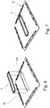
Figur 6 : eine schematische, perspektivische Unteransicht einer Deckplatte des Kombinationsgerätes mit einem Positionierring in Explosionsdarstellung; -
Figur 7 : eine schematische, perspektivische Unteransicht einer Deckplatte des Kombinationsgerätes mit angebrachtem Positionierring; -
Figur 8 : eine schematische Schnittansicht einer Ausführungsform des Kombinationsgerätes im Bereich des Schutzgitters; -
Figur 9 : eine schematische perspektivische Unteransicht einer Ausführungsform des erfindungsgemäßen Positionierrings; -
Figur 10 ; eine schematische Explosionsansicht der Ausführungsform des Positionierrings nachFigur 9 ; -
Figur 11 : eine schematische Draufsicht auf eine Ausführungsform des Positionierrings unter einer durchsichtigen Platte; und -
Figur 12 : eine schematische Schnittansicht einer Ausführungsform des Kombinationsgerätes im Bereich des Schutzgitters; - In
Figur 1 ist eine perspektivische Draufsicht auf eine Ausführungsform eines Kombinationsgerätes 1 gemäß der Erfindung gezeigt. In dieser Ansicht ist das Kombinationsgerät 1 in einer Arbeitsplatte installiert und nur das Kochfeld 2 des Kombinationsgerät 1 ist sichtbar. Insbesondere ist die Deckplatte 20 des Kochfeldes 2 mit der darin eingebrachten Aussparung 200 sichtbar. Unterhalb der Aussparung 200 ist ein Teil der Filtereinheit 3 zu sehen. - In der
Figur 2 ist gezeigt, wie ein in die Aussparung 200 eingebrachtes Schutzgitter 31 korrekt angeordnet ist (linke Darstellung) und wie eine fehlerhafte Ausrichtung des Schutzgitters 31 wirkt (rechte Darstellung). In der rechten Darstellung ist das Schutzgitter 31 nach links verschoben in der Aussparung 200 gehalten. Hierdurch wird das optische Erscheinungsbild des Kombinationsgerätes 1 verschlechtert. - Zudem ist in der
Figur 3 gezeigt, wie bei einer Ausführungsform ohne Positionierring und gegebenenfalls inkorrekt ausgerichtetem Schutzgitter 31 Flüssigkeit in das Innere des Kombinationsgerätes 1 gelangen kann. Durch die Pfeile R ist der Verlauf von Flüssigkeit, die auf dem richtigen Weg in die Aussparung 200 und damit in das Kombinationsgerät 1 eintritt. Hierbei gelangt die Flüssigkeit zu den Filterelementen der Filtereinheit 3, die unterhalb der Aussparung 200 liegt. Durch die Pfeile F ist angedeutet, wie Flüssigkeit versehentlich in den Raum zwischen der Deckplatte 20 und beispielsweise in ein Kochfeldgehäuse eintreten kann, wenn ein seitliches Laufen der Flüssigkeit zwischen der Oberseite der Filtereinheit 3 und dem Schutzgitter nicht abgedeckt ist. - In
Figur 4 ist eine Ausführungsform des erfindungsgemäßen Kombinationsgerätes 1 gezeigt, bevor dieses in eine Arbeitsplatte installiert wird. In dieser Ansicht ist das Gerätegehäuse 10 des Kombinationsgerät 1 sichtbar. Auf dem Gerätegehäuse 10 ist die Deckplatte 20 des Kochfeldes 2 aufgesetzt. In der Aussparung 200 ist das Schutzgitter 31 eingebracht. Wie sich ausFigur 5 ergibt, ist an der Unterseite der Deckplatte 20 ein Positionierrahmen 5 befestigt. Der Positionierrahmen 5 erstreckt sich an der Unterseite der Deckplatte 20 um die Aussparung 200 herum. Vorzugsweise ist der Innenumfang des Positionierrahmens 5 mit dem inneren Umfang der Aussparung 200 ausgerichtet. - Die Befestigung des Positionierrahmens 5 an der Deckplatte 20 ist in den
Figuren 6 und 7 schematisch gezeigt. Der Positionierrahmen 5 kann insbesondere durch Klebstreifen 52 (sieheFigur 10 ), die auf der Oberseite von Laschen des Positionierrahmens 5 aufgebracht werden können, an der Deckplatte 20 fixiert werden. Zusätzlich wird auf die Oberseite des Positionierrahmens 5, insbesondere auf die Oberseite des Trägerrahmens 50 ein haftendes Dichtmittel, beispielsweise Silikon aufgebracht (s.Figur 11 ). Die Funktion der Klebstreifen 52 ist es daher Bewegungen zwischen dem Positionierrahmen 5 und der Deckplatte 20 zu verhindern, während das Silikon aushärtet. Die Klebestreifen dienen daher zur Vorfixierung des Positionierrahmens 5 an der Deckplatte 20. Das Positionieren des Mittelpunktes des Positionierrahmens 5 und der Aussparung 200 muss so genau, wie möglich sein. Eine Abweichung von maximal einigen Zehnteln eines Millimeters können erzielt werden. - Sobald die der Positionierrahmen 5 an der Deckplatte 20 befestigt ist, kann die Deckplatte 20 auf das Kochfeld aufgesetzt werden. Wie in
Figuren 8 und12 zu erkennen ist, liegt der Positionierrahmen 5 dabei im Inneren des Kombinationsgerätes 1 und ist für den Benutzer nicht sichtbar. - Wie sich aus den
Figuren 8 und12 ergibt, umgibt der Positionierring 5 den Rand des Schutzgitters 31, insbesondere eines Flansches des Schutzgitters 31, der sich nach unten erstreckt. Bevorzugt weist der Positionierrahmen 5 zudem mindestens einen Kontaktvorsprung 500 (sieheFigur 9 ) auf, der sich von dem inneren Umfang des Positionierrahmens 5 nach innen erstreckt. Die Kontaktvorsprünge 500 verhindern, dass das Schutzgitter 31 zu dem linken oder rechten Rand der Aussparung 200 rutscht und behält so die korrekten Abstände A und B zwischen dem inneren Rand der Aussparung 200 und dem äußeren Rand des Schutzgitters 31 aufrecht. - Wie in den
Figuren 9 und 10 gezeigt ist, besteht der Positionierrahmen 5 in der gezeigten Ausführungsform aus mehreren Teilen. Insbesondere weist der Positionierrahmen 5 einen Trägerrahmen 50 auf, der aus Kunststoff bestehen kann, einen Dichtring 51, der aus Schaumstoff bestehen kann, und Klebstreifen 52 auf. - Im montierten Zustand des Kombinationsgerätes 1 weist der Dichtring 51 nach unten. Unterhalb der Aussparung 200 ist ein Filtergehäuse 30 der Filtereinheit 3 des Kombinationsgerätes 1 angeordnet. Der Dichtring 51 wird zwischen der Deckplatte 20 und dem Filtergehäuse 30 zusammengedrückt und dichtet den Abstand zwischen diesen Teilen ab.
- Bei der vorliegenden Erfindung hängt die Positionierung Schutzgitter - Aussparung nicht von den weiteren inneren Teilen des Kombinationsgerätes, wie beispielsweise eines Rahmens, inneren Gehäuses und dergleichen ab, die sich zu mehreren Millimetern Toleranz aufsummieren können. Bei der Erfindung ist die Toleranzkette auf die beiden Teile Positionierrahmen und Aussparung sowie den Positioniervorgang des Positionierrahmens an der Deckplatte reduziert.
- Mit der vorliegenden Erfindung wird eine Reihe von Vorteilen erzielt. Insbesondere wird der Positionierrahmen an der Deckplatte vorgesehen, und so auf besondere Weise der Freiheitsgrad des Schutzgitters begrenzt. Der Positionierrahmen kann auch als Zentrierring bezeichnet werden. Zudem kann der Positionierrahmen die Funktion des Abdichtens innerer Bestandteile und der Deckplatte übernehmen, wodurch jegliches Eintreten von Flüssigkeit zu inneren empfindlichen Bestandteilen, die für Sicherheitsaspekte kritisch sind, verhindert werden kann.
- Die beanspruchte Erfindung erlaubt es ein gutes optisches Erscheinungsbild zu schaffen, da gleichzeitig eine ebene obere Oberfläche auf, die frei von Hindernissen für Kochgefäße ist. Zudem ist die Erfindung in der Lage die große Toleranzkette, die zwischen dem Schutzgitter und der Aussparung verläuft, zu korrigieren, wobei ein schlechter direkter Kontakt zwischen beiden Teilen verhindert wird und die Spalte auf den beiden Seiten ähnlich groß sind.
- Die Erfindung fokussiert sich auf einen kritischen aber machbaren Verfahrensschritt des Anklebens des Positionierrahmen, statt bei anderen Alternativen, nämlich der Ausrichtung des gesamten inneren Aufbaus, um mit einer bestimmten Aussparung zusammen zu passen.
-
- 1
- Kombinationsgerät
- 10
- Gerätegehäuse
- 2
- Kochfeld
- 20
- Deckplatte
- 200
- Aussparung
- 3
- Filtereinheit
- 30
- Filtergehäuse
- 31
- Schutzgitter
- 32
- Filterelement
- 4
- Lüfter
- 5
- Positionierrahmen
- 50
- Trägerrahmen
- 500
- Kontaktvorsprung
- 501
- Nut
- 502
- Vertiefung
- 503
- Lasche
- 51
- Dichtring
- 52
- Klebstreifen
- 53
- Dichtmittel
- R
- richtiger Flüssigkeitsverlauf
- F
- Falscher Flüssigkeitsverlauf
- A
- Abstand
- B
- Abstand
Claims (8)
- Kombinationsgerät umfassend ein Kochfeld (2) mit einer Deckplatte (20) und einer Dunstabzugsvorrichtung, dadurch gekennzeichnet, dass das Kombinationsgerät (1) ein Schutzgitter (31) und einen Positionierrahmen (5) zum Positionieren des Schutzgitters (31) in einer Aussparung (200) der Deckplatte (20) aufweist, der an der Deckplatte (20) befestigt ist mit dem Schutzgitter (31) in Kontakt steht.
- Kombinationsgerät nach Anspruch 1, dadurch gekennzeichnet, dass das Schutzgitter (31) in der Aussparung (200) der Deckplatte (20) liegt und die Oberkante des Schutzgitters (31) bündig mit der Oberseite der Deckplatte (20) oder unterhalb der Oberkante der Deckplatte (20) liegt.
- Kombinationsgerät nach einem der Ansprüche 1 oder 2, dadurch gekennzeichnet, dass der Positionierrahmen (5) an der Unterseite der Deckplatte (20) um die Aussparung (200) herum befestigt ist.
- Kombinationsgerät nach einem der Ansprüche 1 bis 3, dadurch gekennzeichnet, dass der Positionierrahmen (5) einen Innenumfang aufweist, der geringer ist, als der Außenumfang des Schutzgitters (31) an der Oberseite des Schutzgitters (31).
- Kombinationsgerät nach Anspruch 4, dadurch gekennzeichnet, dass der Positionierrahmen (5) zumindest einen Vorsprung (500) aufweist, der sich von dem Innenumfang des Positionierrahmens (50) nach innen erstreckt.
- Kombinationsgerät nach einem der Ansprüche 1 bis 5, dadurch gekennzeichnet, dass der Positionierrahmen (5) einen Trägerrahmen (50) und einen Dichtring (51) umfasst, der an der Unterseite des Trägerrahmens (5) gehalten ist.
- Kombinationsgerät nach Anspruch 6, dadurch gekennzeichnet, dass das Kombinationsgerät (1) ein Filtergehäuse (30) aufweist, das unter der Aussparung (200) angeordnet ist und der Dichtring (51) auf der Oberseite des Filtergehäuses (30) aufliegt.
- Kombinationsgerät nach einem der Ansprüche 1 bis 7, dadurch gekennzeichnet, dass der Positionierrahmen (5) durch eine Vorfixierung und eine Klebeverbindung an der Deckplatte (2) befestigt ist.
Applications Claiming Priority (1)
| Application Number | Priority Date | Filing Date | Title |
|---|---|---|---|
| EP19382762 | 2019-09-05 |
Publications (2)
| Publication Number | Publication Date |
|---|---|
| EP3789679A1 true EP3789679A1 (de) | 2021-03-10 |
| EP3789679B1 EP3789679B1 (de) | 2023-05-10 |
Family
ID=67902464
Family Applications (1)
| Application Number | Title | Priority Date | Filing Date |
|---|---|---|---|
| EP20190681.5A Active EP3789679B1 (de) | 2019-09-05 | 2020-08-12 | Kombinationsgerät mit dunstabzugsvorrichtung und kochfeld |
Country Status (2)
| Country | Link |
|---|---|
| EP (1) | EP3789679B1 (de) |
| ES (1) | ES2945190T3 (de) |
Cited By (1)
| Publication number | Priority date | Publication date | Assignee | Title |
|---|---|---|---|---|
| EP4293289A1 (de) * | 2022-06-17 | 2023-12-20 | BORA - Vertriebs GmbH & Co KG | Dunstabzugsvorrichtung zum abzug von kochdünsten nach unten und kochfeldsystem |
Citations (4)
| Publication number | Priority date | Publication date | Assignee | Title |
|---|---|---|---|---|
| US5158068A (en) * | 1991-05-23 | 1992-10-27 | Maytag Corporation | Cooktop cover apparatus |
| DE102013206748A1 (de) * | 2012-04-17 | 2013-10-17 | BSH Bosch und Siemens Hausgeräte GmbH | Rost für eine Dunstabzugsvorrichtung und Dunstabzugsvorrichtung |
| EP3457033A1 (de) * | 2017-09-14 | 2019-03-20 | Berbel Ablufttechnik Gmbh | Dunstabzug zum abzug von auf einem kochfeld erzeugter abluft in vertikal unterhalb einer kochfeldebene weisender richtung |
| CN110160102A (zh) * | 2019-06-13 | 2019-08-23 | 青岛兴邦电子电器有限公司 | 集成有电磁炉灶的下吸式油烟机 |
Family Cites Families (7)
| Publication number | Priority date | Publication date | Assignee | Title |
|---|---|---|---|---|
| US6455818B1 (en) | 2001-08-23 | 2002-09-24 | Maytag Corporation | Downdraft filter assembly for a cooking appliance |
| JP4189236B2 (ja) | 2003-02-28 | 2008-12-03 | 株式会社ハーマンプロ | 調理機器のトッププレート枠 |
| EP3133350B1 (de) | 2015-08-19 | 2020-11-04 | BSH Hausgeräte GmbH | Kombinationsgerät mit kochfeld und dunstabzugsvorrichtung mit filtereinheit |
| KR20190005860A (ko) | 2016-05-10 | 2019-01-16 | 엔오케이 가부시키가이샤 | 개스킷 및 그 장착방법 |
| DE202016008614U1 (de) | 2016-08-23 | 2018-08-23 | Tesa Nie Wieder Bohren Gmbh | Befestigungselement mit nicht durchlässigem Klebering |
| IT201800000794A1 (it) | 2018-01-12 | 2019-07-12 | Elica Spa | Piano cottura con cappa aspirante e bilancia integrate |
| WO2020152288A1 (de) | 2019-01-24 | 2020-07-30 | BSH Hausgeräte GmbH | Dunstabzugsvorrichtung für kochfeld und kombinationsgerät |
-
2020
- 2020-08-12 ES ES20190681T patent/ES2945190T3/es active Active
- 2020-08-12 EP EP20190681.5A patent/EP3789679B1/de active Active
Patent Citations (4)
| Publication number | Priority date | Publication date | Assignee | Title |
|---|---|---|---|---|
| US5158068A (en) * | 1991-05-23 | 1992-10-27 | Maytag Corporation | Cooktop cover apparatus |
| DE102013206748A1 (de) * | 2012-04-17 | 2013-10-17 | BSH Bosch und Siemens Hausgeräte GmbH | Rost für eine Dunstabzugsvorrichtung und Dunstabzugsvorrichtung |
| EP3457033A1 (de) * | 2017-09-14 | 2019-03-20 | Berbel Ablufttechnik Gmbh | Dunstabzug zum abzug von auf einem kochfeld erzeugter abluft in vertikal unterhalb einer kochfeldebene weisender richtung |
| CN110160102A (zh) * | 2019-06-13 | 2019-08-23 | 青岛兴邦电子电器有限公司 | 集成有电磁炉灶的下吸式油烟机 |
Cited By (1)
| Publication number | Priority date | Publication date | Assignee | Title |
|---|---|---|---|---|
| EP4293289A1 (de) * | 2022-06-17 | 2023-12-20 | BORA - Vertriebs GmbH & Co KG | Dunstabzugsvorrichtung zum abzug von kochdünsten nach unten und kochfeldsystem |
Also Published As
| Publication number | Publication date |
|---|---|
| ES2945190T3 (es) | 2023-06-29 |
| EP3789679B1 (de) | 2023-05-10 |
Similar Documents
| Publication | Publication Date | Title |
|---|---|---|
| EP1732375B1 (de) | Gerätelüfter | |
| EP1867375B1 (de) | Filterlüfter mit einer Schnellbefestigungseinrichtung | |
| WO2011020803A1 (de) | Innenrahmen für dunstabzugshaube und dunstabzugshaube | |
| EP3504482B2 (de) | Kombinationsgerät umfassend ein kochfeld und eine dunstabzugsvorrichtung | |
| EP3984337B1 (de) | Explosionsgeschütztes gehäuse mit einem verstärkungsrahmen | |
| EP3978811A1 (de) | Dunstabzugseinheit zum verbau unterhalb eines kochfeldes, geruchsfiltereinheit, dunstabzugssystem und verfahren zum betreiben eines dunstabzugssystems | |
| EP3789679B1 (de) | Kombinationsgerät mit dunstabzugsvorrichtung und kochfeld | |
| EP3346195B1 (de) | Filteranordung für dunstabzugshaube und dunstabzugshaube | |
| WO2008138760A1 (de) | Kocheinheitsschutzvorrichtung | |
| EP2469188B1 (de) | Dunstabzugshaube | |
| DE102007012481A1 (de) | Kochfeld mit einem Zierrahmen und einem damit verbundenen Montagerahmen | |
| EP3101350A1 (de) | Lüftergehäuse für dunstabzugshaube, lüftereinheit für dunstabzugshaube und dunstabzugshaube | |
| EP3293458A1 (de) | Dunstabzugsvorrichtung mit elektrokasten | |
| DE102010003901A1 (de) | Aufhängsicherung für Essen und Hauben | |
| DE102009055077A1 (de) | Lüfterkasten für Dunstabzugshaube | |
| EP4105564B1 (de) | Kombinationsgerät | |
| DE10066168B4 (de) | Dichtungsanordnung für ein Kraftfahrzeug und Verfahren zur Montage eines Führungs- und Dichtungsprofils an einem Rahmen | |
| EP1441181B1 (de) | Gehäuse für eine Dunstabzugshaube | |
| DE102009055075A1 (de) | Lüfterkasten für Dunstabzugshaube | |
| EP3112762B1 (de) | Hängeschrank mit dunstabzugshaube und haltevorrichtung | |
| DE102020202370A1 (de) | Kombinationsgerät mit Kochfeld und Dunstabzugsvorrichtung und Verfahren zum Betreiben eines Kombinationsgerätes | |
| DE10350586B4 (de) | Haushaltsgerät mit einer Bedienleiste | |
| EP4641095A1 (de) | Dunstabzugshaube mit luftleitvorrichtung | |
| DE4034774C2 (de) | ||
| EP0735327A2 (de) | Verkleidung für einen Plattenheizkörper |
Legal Events
| Date | Code | Title | Description |
|---|---|---|---|
| PUAI | Public reference made under article 153(3) epc to a published international application that has entered the european phase |
Free format text: ORIGINAL CODE: 0009012 |
|
| STAA | Information on the status of an ep patent application or granted ep patent |
Free format text: STATUS: THE APPLICATION HAS BEEN PUBLISHED |
|
| AK | Designated contracting states |
Kind code of ref document: A1 Designated state(s): AL AT BE BG CH CY CZ DE DK EE ES FI FR GB GR HR HU IE IS IT LI LT LU LV MC MK MT NL NO PL PT RO RS SE SI SK SM TR |
|
| AX | Request for extension of the european patent |
Extension state: BA ME |
|
| STAA | Information on the status of an ep patent application or granted ep patent |
Free format text: STATUS: REQUEST FOR EXAMINATION WAS MADE |
|
| 17P | Request for examination filed |
Effective date: 20210910 |
|
| RBV | Designated contracting states (corrected) |
Designated state(s): AL AT BE BG CH CY CZ DE DK EE ES FI FR GB GR HR HU IE IS IT LI LT LU LV MC MK MT NL NO PL PT RO RS SE SI SK SM TR |
|
| GRAP | Despatch of communication of intention to grant a patent |
Free format text: ORIGINAL CODE: EPIDOSNIGR1 |
|
| STAA | Information on the status of an ep patent application or granted ep patent |
Free format text: STATUS: GRANT OF PATENT IS INTENDED |
|
| INTG | Intention to grant announced |
Effective date: 20230104 |
|
| GRAS | Grant fee paid |
Free format text: ORIGINAL CODE: EPIDOSNIGR3 |
|
| GRAA | (expected) grant |
Free format text: ORIGINAL CODE: 0009210 |
|
| STAA | Information on the status of an ep patent application or granted ep patent |
Free format text: STATUS: THE PATENT HAS BEEN GRANTED |
|
| AK | Designated contracting states |
Kind code of ref document: B1 Designated state(s): AL AT BE BG CH CY CZ DE DK EE ES FI FR GB GR HR HU IE IS IT LI LT LU LV MC MK MT NL NO PL PT RO RS SE SI SK SM TR |
|
| REG | Reference to a national code |
Ref country code: GB Ref legal event code: FG4D Free format text: NOT ENGLISH |
|
| REG | Reference to a national code |
Ref country code: AT Ref legal event code: REF Ref document number: 1566995 Country of ref document: AT Kind code of ref document: T Effective date: 20230515 Ref country code: CH Ref legal event code: EP |
|
| REG | Reference to a national code |
Ref country code: DE Ref legal event code: R096 Ref document number: 502020003229 Country of ref document: DE |
|
| REG | Reference to a national code |
Ref country code: IE Ref legal event code: FG4D Free format text: LANGUAGE OF EP DOCUMENT: GERMAN |
|
| REG | Reference to a national code |
Ref country code: ES Ref legal event code: FG2A Ref document number: 2945190 Country of ref document: ES Kind code of ref document: T3 Effective date: 20230629 |
|
| REG | Reference to a national code |
Ref country code: NL Ref legal event code: FP |
|
| REG | Reference to a national code |
Ref country code: LT Ref legal event code: MG9D |
|
| PG25 | Lapsed in a contracting state [announced via postgrant information from national office to epo] |
Ref country code: SE Free format text: LAPSE BECAUSE OF FAILURE TO SUBMIT A TRANSLATION OF THE DESCRIPTION OR TO PAY THE FEE WITHIN THE PRESCRIBED TIME-LIMIT Effective date: 20230510 Ref country code: PT Free format text: LAPSE BECAUSE OF FAILURE TO SUBMIT A TRANSLATION OF THE DESCRIPTION OR TO PAY THE FEE WITHIN THE PRESCRIBED TIME-LIMIT Effective date: 20230911 Ref country code: NO Free format text: LAPSE BECAUSE OF FAILURE TO SUBMIT A TRANSLATION OF THE DESCRIPTION OR TO PAY THE FEE WITHIN THE PRESCRIBED TIME-LIMIT Effective date: 20230810 |
|
| PG25 | Lapsed in a contracting state [announced via postgrant information from national office to epo] |
Ref country code: RS Free format text: LAPSE BECAUSE OF FAILURE TO SUBMIT A TRANSLATION OF THE DESCRIPTION OR TO PAY THE FEE WITHIN THE PRESCRIBED TIME-LIMIT Effective date: 20230510 Ref country code: PL Free format text: LAPSE BECAUSE OF FAILURE TO SUBMIT A TRANSLATION OF THE DESCRIPTION OR TO PAY THE FEE WITHIN THE PRESCRIBED TIME-LIMIT Effective date: 20230510 Ref country code: LV Free format text: LAPSE BECAUSE OF FAILURE TO SUBMIT A TRANSLATION OF THE DESCRIPTION OR TO PAY THE FEE WITHIN THE PRESCRIBED TIME-LIMIT Effective date: 20230510 Ref country code: LT Free format text: LAPSE BECAUSE OF FAILURE TO SUBMIT A TRANSLATION OF THE DESCRIPTION OR TO PAY THE FEE WITHIN THE PRESCRIBED TIME-LIMIT Effective date: 20230510 Ref country code: IS Free format text: LAPSE BECAUSE OF FAILURE TO SUBMIT A TRANSLATION OF THE DESCRIPTION OR TO PAY THE FEE WITHIN THE PRESCRIBED TIME-LIMIT Effective date: 20230910 Ref country code: HR Free format text: LAPSE BECAUSE OF FAILURE TO SUBMIT A TRANSLATION OF THE DESCRIPTION OR TO PAY THE FEE WITHIN THE PRESCRIBED TIME-LIMIT Effective date: 20230510 Ref country code: GR Free format text: LAPSE BECAUSE OF FAILURE TO SUBMIT A TRANSLATION OF THE DESCRIPTION OR TO PAY THE FEE WITHIN THE PRESCRIBED TIME-LIMIT Effective date: 20230811 |
|
| PG25 | Lapsed in a contracting state [announced via postgrant information from national office to epo] |
Ref country code: FI Free format text: LAPSE BECAUSE OF FAILURE TO SUBMIT A TRANSLATION OF THE DESCRIPTION OR TO PAY THE FEE WITHIN THE PRESCRIBED TIME-LIMIT Effective date: 20230510 |
|
| PG25 | Lapsed in a contracting state [announced via postgrant information from national office to epo] |
Ref country code: SK Free format text: LAPSE BECAUSE OF FAILURE TO SUBMIT A TRANSLATION OF THE DESCRIPTION OR TO PAY THE FEE WITHIN THE PRESCRIBED TIME-LIMIT Effective date: 20230510 |
|
| PG25 | Lapsed in a contracting state [announced via postgrant information from national office to epo] |
Ref country code: SM Free format text: LAPSE BECAUSE OF FAILURE TO SUBMIT A TRANSLATION OF THE DESCRIPTION OR TO PAY THE FEE WITHIN THE PRESCRIBED TIME-LIMIT Effective date: 20230510 Ref country code: SK Free format text: LAPSE BECAUSE OF FAILURE TO SUBMIT A TRANSLATION OF THE DESCRIPTION OR TO PAY THE FEE WITHIN THE PRESCRIBED TIME-LIMIT Effective date: 20230510 Ref country code: RO Free format text: LAPSE BECAUSE OF FAILURE TO SUBMIT A TRANSLATION OF THE DESCRIPTION OR TO PAY THE FEE WITHIN THE PRESCRIBED TIME-LIMIT Effective date: 20230510 Ref country code: EE Free format text: LAPSE BECAUSE OF FAILURE TO SUBMIT A TRANSLATION OF THE DESCRIPTION OR TO PAY THE FEE WITHIN THE PRESCRIBED TIME-LIMIT Effective date: 20230510 Ref country code: DK Free format text: LAPSE BECAUSE OF FAILURE TO SUBMIT A TRANSLATION OF THE DESCRIPTION OR TO PAY THE FEE WITHIN THE PRESCRIBED TIME-LIMIT Effective date: 20230510 Ref country code: CZ Free format text: LAPSE BECAUSE OF FAILURE TO SUBMIT A TRANSLATION OF THE DESCRIPTION OR TO PAY THE FEE WITHIN THE PRESCRIBED TIME-LIMIT Effective date: 20230510 |
|
| REG | Reference to a national code |
Ref country code: DE Ref legal event code: R026 Ref document number: 502020003229 Country of ref document: DE |
|
| PLBI | Opposition filed |
Free format text: ORIGINAL CODE: 0009260 |
|
| PLAX | Notice of opposition and request to file observation + time limit sent |
Free format text: ORIGINAL CODE: EPIDOSNOBS2 |
|
| PG25 | Lapsed in a contracting state [announced via postgrant information from national office to epo] |
Ref country code: MC Free format text: LAPSE BECAUSE OF FAILURE TO SUBMIT A TRANSLATION OF THE DESCRIPTION OR TO PAY THE FEE WITHIN THE PRESCRIBED TIME-LIMIT Effective date: 20230510 |
|
| 26 | Opposition filed |
Opponent name: BORA - VERTRIEBS GMBH & CO KG Effective date: 20240209 Opponent name: ELECTROLUX ROTHENBURG GMBH FACTORY AND DEVELOPMENT Effective date: 20240209 Opponent name: BERBEL ABLUFTTECHNIK GMBH Effective date: 20240208 |
|
| REG | Reference to a national code |
Ref country code: CH Ref legal event code: PL |
|
| PG25 | Lapsed in a contracting state [announced via postgrant information from national office to epo] |
Ref country code: MC Free format text: LAPSE BECAUSE OF FAILURE TO SUBMIT A TRANSLATION OF THE DESCRIPTION OR TO PAY THE FEE WITHIN THE PRESCRIBED TIME-LIMIT Effective date: 20230510 |
|
| PG25 | Lapsed in a contracting state [announced via postgrant information from national office to epo] |
Ref country code: LU Free format text: LAPSE BECAUSE OF NON-PAYMENT OF DUE FEES Effective date: 20230812 |
|
| PG25 | Lapsed in a contracting state [announced via postgrant information from national office to epo] |
Ref country code: LU Free format text: LAPSE BECAUSE OF NON-PAYMENT OF DUE FEES Effective date: 20230812 Ref country code: CH Free format text: LAPSE BECAUSE OF NON-PAYMENT OF DUE FEES Effective date: 20230831 |
|
| PG25 | Lapsed in a contracting state [announced via postgrant information from national office to epo] |
Ref country code: SI Free format text: LAPSE BECAUSE OF FAILURE TO SUBMIT A TRANSLATION OF THE DESCRIPTION OR TO PAY THE FEE WITHIN THE PRESCRIBED TIME-LIMIT Effective date: 20230510 |
|
| REG | Reference to a national code |
Ref country code: BE Ref legal event code: MM Effective date: 20230831 |
|
| REG | Reference to a national code |
Ref country code: IE Ref legal event code: MM4A |
|
| PG25 | Lapsed in a contracting state [announced via postgrant information from national office to epo] |
Ref country code: SI Free format text: LAPSE BECAUSE OF FAILURE TO SUBMIT A TRANSLATION OF THE DESCRIPTION OR TO PAY THE FEE WITHIN THE PRESCRIBED TIME-LIMIT Effective date: 20230510 Ref country code: IT Free format text: LAPSE BECAUSE OF FAILURE TO SUBMIT A TRANSLATION OF THE DESCRIPTION OR TO PAY THE FEE WITHIN THE PRESCRIBED TIME-LIMIT Effective date: 20230510 |
|
| PLBB | Reply of patent proprietor to notice(s) of opposition received |
Free format text: ORIGINAL CODE: EPIDOSNOBS3 |
|
| PG25 | Lapsed in a contracting state [announced via postgrant information from national office to epo] |
Ref country code: IE Free format text: LAPSE BECAUSE OF NON-PAYMENT OF DUE FEES Effective date: 20230812 |
|
| PG25 | Lapsed in a contracting state [announced via postgrant information from national office to epo] |
Ref country code: IE Free format text: LAPSE BECAUSE OF NON-PAYMENT OF DUE FEES Effective date: 20230812 |
|
| PG25 | Lapsed in a contracting state [announced via postgrant information from national office to epo] |
Ref country code: BE Free format text: LAPSE BECAUSE OF NON-PAYMENT OF DUE FEES Effective date: 20230831 |
|
| PG25 | Lapsed in a contracting state [announced via postgrant information from national office to epo] |
Ref country code: BG Free format text: LAPSE BECAUSE OF FAILURE TO SUBMIT A TRANSLATION OF THE DESCRIPTION OR TO PAY THE FEE WITHIN THE PRESCRIBED TIME-LIMIT Effective date: 20230510 |
|
| PG25 | Lapsed in a contracting state [announced via postgrant information from national office to epo] |
Ref country code: BG Free format text: LAPSE BECAUSE OF FAILURE TO SUBMIT A TRANSLATION OF THE DESCRIPTION OR TO PAY THE FEE WITHIN THE PRESCRIBED TIME-LIMIT Effective date: 20230510 |
|
| PLBP | Opposition withdrawn |
Free format text: ORIGINAL CODE: 0009264 |
|
| PG25 | Lapsed in a contracting state [announced via postgrant information from national office to epo] |
Ref country code: CY Free format text: LAPSE BECAUSE OF FAILURE TO SUBMIT A TRANSLATION OF THE DESCRIPTION OR TO PAY THE FEE WITHIN THE PRESCRIBED TIME-LIMIT; INVALID AB INITIO Effective date: 20200812 |
|
| PG25 | Lapsed in a contracting state [announced via postgrant information from national office to epo] |
Ref country code: HU Free format text: LAPSE BECAUSE OF FAILURE TO SUBMIT A TRANSLATION OF THE DESCRIPTION OR TO PAY THE FEE WITHIN THE PRESCRIBED TIME-LIMIT; INVALID AB INITIO Effective date: 20200812 |
|
| PLBP | Opposition withdrawn |
Free format text: ORIGINAL CODE: 0009264 |
|
| PGFP | Annual fee paid to national office [announced via postgrant information from national office to epo] |
Ref country code: NL Payment date: 20250821 Year of fee payment: 6 |
|
| PGFP | Annual fee paid to national office [announced via postgrant information from national office to epo] |
Ref country code: ES Payment date: 20250917 Year of fee payment: 6 |
|
| PGFP | Annual fee paid to national office [announced via postgrant information from national office to epo] |
Ref country code: DE Payment date: 20250831 Year of fee payment: 6 |
|
| PGFP | Annual fee paid to national office [announced via postgrant information from national office to epo] |
Ref country code: GB Payment date: 20250822 Year of fee payment: 6 |
|
| PGFP | Annual fee paid to national office [announced via postgrant information from national office to epo] |
Ref country code: AT Payment date: 20251020 Year of fee payment: 5 Ref country code: FR Payment date: 20250821 Year of fee payment: 6 |
|
| PLBP | Opposition withdrawn |
Free format text: ORIGINAL CODE: 0009264 |
|
| REG | Reference to a national code |
Ref country code: CH Ref legal event code: L10 Free format text: ST27 STATUS EVENT CODE: U-0-0-L10-L00 (AS PROVIDED BY THE NATIONAL OFFICE) Effective date: 20251203 |
|
| PG25 | Lapsed in a contracting state [announced via postgrant information from national office to epo] |
Ref country code: TR Free format text: LAPSE BECAUSE OF FAILURE TO SUBMIT A TRANSLATION OF THE DESCRIPTION OR TO PAY THE FEE WITHIN THE PRESCRIBED TIME-LIMIT Effective date: 20230510 |
|
| PLBD | Termination of opposition procedure: decision despatched |
Free format text: ORIGINAL CODE: EPIDOSNOPC1 |
|
| REG | Reference to a national code |
Ref country code: DE Ref legal event code: R100 Ref document number: 502020003229 Country of ref document: DE |
|
| PLBM | Termination of opposition procedure: date of legal effect published |
Free format text: ORIGINAL CODE: 0009276 |
|
| REG | Reference to a national code |
Ref country code: CH Ref legal event code: L10 Free format text: ST27 STATUS EVENT CODE: U-0-0-L10-L00 (AS PROVIDED BY THE NATIONAL OFFICE) Effective date: 20260402 |
|
| 27C | Opposition proceedings terminated |
Effective date: 20251218 |