EP3789706B1 - Élément de montage pour le montage d'un panneau décoratif sur un appareil domestique intégré - Google Patents
Élément de montage pour le montage d'un panneau décoratif sur un appareil domestique intégré Download PDFInfo
- Publication number
- EP3789706B1 EP3789706B1 EP20193611.9A EP20193611A EP3789706B1 EP 3789706 B1 EP3789706 B1 EP 3789706B1 EP 20193611 A EP20193611 A EP 20193611A EP 3789706 B1 EP3789706 B1 EP 3789706B1
- Authority
- EP
- European Patent Office
- Prior art keywords
- base
- additional
- mounting member
- holders
- decorative panel
- Prior art date
- Legal status (The legal status is an assumption and is not a legal conclusion. Google has not performed a legal analysis and makes no representation as to the accuracy of the status listed.)
- Active
Links
Images


Classifications
-
- F—MECHANICAL ENGINEERING; LIGHTING; HEATING; WEAPONS; BLASTING
- F25—REFRIGERATION OR COOLING; COMBINED HEATING AND REFRIGERATION SYSTEMS; HEAT PUMP SYSTEMS; MANUFACTURE OR STORAGE OF ICE; LIQUEFACTION SOLIDIFICATION OF GASES
- F25D—REFRIGERATORS; COLD ROOMS; ICE-BOXES; COOLING OR FREEZING APPARATUS NOT OTHERWISE PROVIDED FOR
- F25D23/00—General constructional features
- F25D23/10—Arrangements for mounting in particular locations, e.g. for built-in type, for corner type
Definitions
- the present invention relates to a mounting member which is used for the mounting of the decorative panels onto the built-in household appliances.
- the built-in household appliances are placed into a cabinet and decorative panels which suit the properties of the cabinet have to be mounted onto the same.
- the positioning of the decorative panels is critical both aesthetically and functionally.
- the mounting process is performed by authorized service personnel by taking precise measurements.
- the mounting process is a substantially time consuming and laborious process.
- German Patent Application No. DE102017130849 a mounting member is disclosed, which is placed into the cabinet and which enables the decorative panel to be mounted onto the built-in household appliance.
- German Patent Application No. DE19852330 a household appliance having door and means for attaching a door leaf to the door is disclosed.
- the aim of the present invention is the realization of a mounting member which is used for the precise and easy mounting of the decorative panels onto the built-in household appliances.
- the mounting member realized in order to attain the aim of the present invention, explicated in the first claim and the respective claims thereof, is a member used for the mounting of the decorative panel onto a built-in household appliance, and comprises a base which is seated on the base of the cabinet; an additional base which extends towards the base and the body of the built-in household appliance; a first carrier having an extension which extends between the body of the household appliance and the door, perpendicular to the base and the additional base and an additional extension which extends downwards outside the cabinet from the other end of the base, perpendicular to the base and which has holders extending outwards; and a second carrier which is attached to the lower edge of the decorative panel, which moves on the additional extension upwards and downwards in the vertical direction and which has additional holders matching the form of the holders on the additional extension at the side thereof facing the additional extension so as to engage with the holders.
- the first carrier is placed to the lower front section of the cabinet and the built-in household appliance.
- the base of the first carrier extends towards the base of the cabinet and the additional base extends under the body of the built-in household appliance which is at a distance from the base of the cabinet while the extension is positioned between the body and the door of the built-in household appliance and the additional extension extends downwards from the front of the cabinet.
- the second carrier which is attached under the decorative panel is attached to the first carrier together with the decorative panel such that the additional holders engage with the holders on the first carrier.
- the horizontal and vertical positions of the decorative panel on the door are determined precisely by adjusting the relative positions of the holders and the additional holders with respect to each other.
- the mounting member is removed from the cabinet and the decorative panel after the decorative panel is fixed to the door.
- heights of the base and the additional panel are different from each other.
- a support member extending from the base towards the additional base is provided at the corner between the additional base and the base.
- the mounting member comprises a plurality of holders which extend in a plurality of rows perpendicular to the horizontal plane of the additional extension.
- mounting member further comprises a plurality of additional holders with the same form as the holder, arranged on the surface of the second carrier which faces the first carrier.
- the mounting member comprises one or more than one fixing member which is provided on the door, enabling the decorative panel to be attached from the upper section thereof after the decorative panel is attached to the door from the lower section by means of the first and second carriers attached to each other.
- the fixing member enables the decorative panel to be attached to the door temporarily after the decorative panel is attached to the door from the lower section. After the completion of this process, the fixing member is removed from the door and the decorative panel is fixed onto the door permanently by means of fixing means. The temporary attachment of the decorative panel onto the door is performed by means of adhesives.
- the second carrier is h-shaped.
- the additional holders are arranged on the back of the second carrier.
- the mounting member is used for fixing decorative panels onto the lower and upper doors of the built-in cooling devices which are placed into cabinets and which have lower and upper doors.
- the required distance between the lower and upper doors is adjusted by means of the mounting member.
- the decorative panels which are fixed onto the lower and upper doors are enabled to be grouped on the same plane so as to be aligned with each other.
- the decorative panel is enabled to be attached to the door precisely and easily without the need for taking measurements on the built-in household appliance and the decorative panel. Furthermore, as the position of the decorative panel on the door is determined without taking measurements, the need for the service personnel to use measurement devices is eliminated, thus decreasing the time, cost and labor needed to place the built-in household appliance into the cabinet.
- the mounting member further decreases the service failure rate by preventing the built-in household appliance from being grouped wrongly in the cabinet.
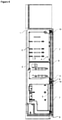
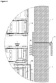
- the mounting member (8) is a member used for mounting the decorative panel (7) onto a built-in household appliance (2) which is placed into the cabinet (1), and comprises a first carrier (9) having a base (11) which is seated onto the base of the cabinet (1), an additional base (12) which extends towards the base (11) and under of the body (3) of the built-in household appliance (2), an extension (13) which extends between the body (3) and the door (4), perpendicular to the base (11) and the additional base (12), and an additional extension (14) which extends downwards from the other end of the base (11) extending out of the cabinet (1), perpendicular to the base (11) and which has one or more than one holder (15) thereon; and a second carrier (10) which is attached to the lower edge of the decorative panel (7), which moves on the additional extension (14) upwards and downwards in the vertical direction and which has additional holders (16) on the side thereof facing the additional extension (14), matching the form of the holders (15) on the additional extension (14) so as to engage with the same ( Figure 1 and Figure
- the first carrier (9) is placed to the lower front section of the cabinet (1) and the built-in household appliance (2).
- the base (11) of the first carrier (9) extends towards the base of the cabinet (1) while the additional base (12) extends towards the base of the body (3) which is at a distance from the bottom of the cabinet (1).
- the extension (13) is positioned between the body (3) and the door (4) of the built-in household appliance (2) while the additional extension (14) extends downwards from the front side of the cabinet (1).
- the second carrier (10) which is attached under the decorative panel (7) is moved closer and attached to the first carrier (9) together with the decorative panel (7) such that the additional holders (16) engage with the holders (15) on the first carrier (9).
- the horizontal and vertical positions of the decorative panel (7) on the door (4) are determined precisely by adjusting the relative positions of the holders (15) and the additional holders (16) with respect to each other.
- the decorative panel (7) is fixed onto the door (4) and the mounting member (8) is removed from the cabinet (1) and the decorative panel (7).
- the first carrier (9) is prevented from sliding and moving forwards and backwards on the base of the cabinet (1) ( Figure 3 and Figure 4 ).
- the mounting member (8) comprises the base (11) and the additional base (12) which are at different heights.
- the mounting member (8) comprises a support member (17) at the corner between the additional base (12) and the base (11), extending from the base (11) towards additional base (12). The flexing and breaking of the additional base (12) due to the distance between the base (11) and the additional base (12) is prevented by means of the support member (17).
- the mounting member (8) comprises a plurality of holders (15) which extend in a plurality of rows perpendicular to the horizontal plane of the additional extension (14).
- the mounting member (8) further comprises a plurality of additional holders (16) with the same form as the holder (15), arranged on the surface of the second carrier (10) which faces the first carrier (9).
- the holders (15) extend outwards from the surface of the additional extension (14) so as to be inclined upwards while the additional holders (16) extend so as to be inclined downwards. Thereby, the holder (15) and the additional holders (16) are prevented from being broken due to weight and sliding in the vertical direction.
- the mounting member (8) comprises one or more than one fixing member (18) which are provided on the door (4), enabling the decorative panel (7) to be attached from the upper section thereof after the decorative panel (7) is attached to the door (4) from the lower section by means of the first and second carriers (9 and 10) attached to each other.
- the fixing member (18) enables the decorative panel (7) to be attached to the door (4) temporarily after the decorative panel (7) is attached to the door (4) from the lower section thereof.
- the fixing member (18) is removed from the door (4) and the decorative panel (7) is fixed onto the door (4) permanently by means of fixing means.
- the temporary attachment of the decorative panel (7) onto the door (4) is performed by means of adhesives ( Figure 5 , Figure 6 and Figure 7 ).
- the second carrier (10) is h-shaped.
- the additional holders (16) are arranged on the back of the second carrier (10).
- the mounting member (8) is used for fixing decorative panels (7) onto the lower and upper doors (5 and 6) of the built-in cooling devices which are placed into cabinets (1) and which have lower and upper doors (5 and 6).
- the required distance between the lower and upper doors (5 and 6) is adjusted by means of the mounting member (8).
- the decorative panels (7) which are fixed onto the lower and upper doors (5 and 6) are enabled to be grouped on the same plane so as to be aligned with each other ( Figure 8 and Figure 9 ).
- the decorative panel (7) is enabled to be attached to the door (4) precisely and easily without the need for taking measurements on the built-in household appliance (2) and the decorative panel (7). Furthermore, as the position of the decorative panel (7) is determined without taking measurements, the need for the service personnel to use measurement devices is eliminated, thus decreasing the time, cost and labor needed to place the built-in household appliance (2) into the cabinet (1).
- the mounting member (8) further decreases the service failure rate by preventing the built-in household appliance (2) from being grouped wrongly in the cabinet (1).
Landscapes
- Engineering & Computer Science (AREA)
- Chemical & Material Sciences (AREA)
- Combustion & Propulsion (AREA)
- Physics & Mathematics (AREA)
- Mechanical Engineering (AREA)
- Thermal Sciences (AREA)
- General Engineering & Computer Science (AREA)
- Combinations Of Kitchen Furniture (AREA)
- Casings For Electric Apparatus (AREA)
Claims (11)
- Un élément de montage (8) pour le montage d'un panneau décoratif (7) sur un appareil électroménager intégré (2) ayant un corps (3) et une porte (4), l'appareil électroménager étant placé dans un meuble (1), l'élément de montage (8) comprenant un premier porteur (9) ayant une base (11) qui est monté sur le fond du meuble (1), une base supplémentaire (12) qui s'étend vers la base (11) et sous le corps (3) de l'appareil électroménager intégré (2), et une extension supplémentaire (14) qui s'étend vers le bas à partir d'une autre extrémité de la base (11) s'étendant hors du meuble (1), perpendiculaire à la base (11) et qui a des supports (15) dessus ; et un second porteur (10) qui est fixé au bord inférieur du panneau décoratif (7), qui se déplace sur l'extension supplémentaire (14) vers le haut et vers le bas dans la direction verticale et qui a des supports supplémentaires (16) sur son côté faisant face à l'extension supplémentaire (14), s'appariant avec la forme des supports (15) sur l'extension supplémentaire (14) de manière à s'engager avec celle-ci, l'élément de montage (8) étant caractérisé en ce qu'il comprend en outre une extension (13) qui s'étend entre le corps (3) et la porte (4), perpendiculaire à la base (11) et une base supplémentaire (12).
- Un élément de montage (8) selon la Revendication 1, caractérisé par la base (11) et la base supplémentaire (12) qui sont à des hauteurs différentes.
- Un élément de montage (8) selon la Revendication 2, caractérisé par un élément de support (17) à l'angle entre la base supplémentaire (12) et la base (11), s'étendant de la base (11) vers la base supplémentaire (12).
- Un élément de montage (8) selon la Revendication 1, caractérisé par une pluralité de supports (15) qui s'étendent en une pluralité de rangées perpendiculaires au plan horizontal de l'extension supplémentaire (14).
- Un élément de montage (8) selon la Revendication 4, caractérisé par une pluralité de supports supplémentaires (16) ayant la même forme que le support (5), disposés sur la surface du second porteur (10) qui fait face au premier porteur (9).
- Un élément de montage (8) selon la Revendication 4, caractérisé par les supports (15) qui s'étendent vers l'extérieur depuis la surface de l'extension supplémentaire (14) de manière à être inclinés vers le haut.
- Un élément de montage (8) selon la Revendication 5 et la Revendication 6, caractérisé par les supports supplémentaires (16) qui s'étendent de manière à être inclinés vers le bas.
- Un élément de montage (8) selon la Revendication 1, caractérisé par un ou plusieurs éléments de fixation (18) disposés sur la porte (4), permettant de fixer le panneau décoratif (7) à partir de sa partie supérieure.
- Un élément de montage (8) selon la Revendication 1, caractérisé par le second porteur (10) qui est en forme de H.
- Un élément de montage (8) selon la Revendication 1 et 5 et 7 et 9, caractérisé par les supports supplémentaires (16) qui sont disposés à l'arrière du second porteur (10).
- Un élément de montage (8) selon l'une quelconque des Revendications cidessus, adapté pour la fixation de panneaux décoratifs (7) sur les portes inférieures et supérieures (5 et 6) des dispositifs de refroidissement intégrés qui sont placés dans des meubles (1) et qui ont des portes inférieures et supérieures (5 et 6).
Priority Applications (1)
| Application Number | Priority Date | Filing Date | Title |
|---|---|---|---|
| PL20193611T PL3789706T3 (pl) | 2019-09-05 | 2020-08-31 | Element montażowy do montażu panelu dekoracyjnego do urządzenia gospodarstwa domowego do zabudowy |
Applications Claiming Priority (1)
| Application Number | Priority Date | Filing Date | Title |
|---|---|---|---|
| TR201913434 | 2019-09-05 |
Publications (2)
| Publication Number | Publication Date |
|---|---|
| EP3789706A1 EP3789706A1 (fr) | 2021-03-10 |
| EP3789706B1 true EP3789706B1 (fr) | 2022-03-09 |
Family
ID=72292360
Family Applications (1)
| Application Number | Title | Priority Date | Filing Date |
|---|---|---|---|
| EP20193611.9A Active EP3789706B1 (fr) | 2019-09-05 | 2020-08-31 | Élément de montage pour le montage d'un panneau décoratif sur un appareil domestique intégré |
Country Status (2)
| Country | Link |
|---|---|
| EP (1) | EP3789706B1 (fr) |
| PL (1) | PL3789706T3 (fr) |
Family Cites Families (8)
| Publication number | Priority date | Publication date | Assignee | Title |
|---|---|---|---|---|
| EP0718459B1 (fr) | 1994-10-25 | 2003-04-02 | Whirlpool Europe B.V. | Procédé et dispositif pour la fixation d'un vantail de porte sur la porte d'un appareil ménager intégré |
| DE4443852C1 (de) * | 1994-10-25 | 1995-12-07 | Bauknecht Hausgeraete | Verfahren und Vorrichtung zum Anbringen eines Türblattes an der Gerätetür eines eingebauten Haushalt-Einbaugerätes |
| DE19644734C1 (de) * | 1996-10-28 | 1998-05-07 | Bauknecht Hausgeraete | Verfahren zum Anbringen eines Türblattes an der Gerätetür eines eingebauten Haushalt-Einbaugerätes |
| DE19712418C1 (de) * | 1997-03-25 | 1998-04-30 | Whirlpool Co | Verfahren zum Anbringen eines Türblattes an der Gerätetür eines eingebauten Haushalt-Einbaugerätes |
| DE19852330C2 (de) * | 1998-11-13 | 2000-10-05 | Aeg Hausgeraete Gmbh | Haushaltsgerät mit einer Gerätetür und Mitteln zur Anbringung eines Türblattes an der Gerätetür und Verfahren zur Anbringung eines Türblattes an der Gerätetür eines Haushaltsgerätes |
| FR2802787B3 (fr) | 1999-12-22 | 2001-10-26 | Merlomi Elettrodomestici Spa S | Appareil electromenager encastrable, notamment refrigerateur equipe de dispositifs de reglage millimetrique de la position de l'habillage frontal de finition |
| WO2014177226A1 (fr) | 2013-05-03 | 2014-11-06 | Arcelik Anonim Sirketi | Ensemble de montage pour la fixation d'un panneau décoratif sur un appareil électroménager encastré et procédé de montage |
| SI25343A (sl) | 2017-01-16 | 2018-07-31 | Gorenje Gospodinjski Aparati D.D. | Vgradni gospodinjski aparat z okrasnim panelom |
-
2020
- 2020-08-31 EP EP20193611.9A patent/EP3789706B1/fr active Active
- 2020-08-31 PL PL20193611T patent/PL3789706T3/pl unknown
Also Published As
| Publication number | Publication date |
|---|---|
| PL3789706T3 (pl) | 2022-06-27 |
| EP3789706A1 (fr) | 2021-03-10 |
Similar Documents
| Publication | Publication Date | Title |
|---|---|---|
| US8840205B2 (en) | Refrigerator appliance and a shelf assembly for the same | |
| EP2854599B1 (fr) | Appareil électroménager encastré comprenant un panneau décoratif | |
| EP1925251B1 (fr) | Panier pour lave-vaisselle | |
| US9650789B2 (en) | Attachment brackets for panel mounting | |
| WO2013045543A1 (fr) | Crémaillère adaptée à être utilisée dans un lave-vaisselle et lave-vaisselle dans lequel la crémaillère est utilisée | |
| EP3599937B1 (fr) | Tiroir pour système de stockage mural | |
| US11297694B2 (en) | Range with suspended cooktop | |
| EP2820998B1 (fr) | Ensemble de panier pour un lave-vaisselle | |
| EP2074925B1 (fr) | Tablettes pour panier de lave-vaisselle | |
| EP2017417B1 (fr) | Agencement de porte coulissante de penderie | |
| EP3789706B1 (fr) | Élément de montage pour le montage d'un panneau décoratif sur un appareil domestique intégré | |
| CN101677745B (zh) | 用于洗碗机的台下安装系统及相关方法 | |
| EP3167755B1 (fr) | Ensemble de coulisse de tiroir | |
| EP1145667B1 (fr) | Procédé de fixation d'une porte de placard à une porte d'un réfrigérateur intégré | |
| EP3397129B1 (fr) | Lave-vaisselle | |
| DK2664252T3 (en) | Height adjustable furniture | |
| CN207335276U (zh) | 可调节冷柜层架支架 | |
| CN109990349B (zh) | 一种吸油烟机的安装结构 | |
| EP3141850B1 (fr) | Système d'étagère | |
| US20120146474A1 (en) | Positioning base with adjustable support levelers for a household appliance | |
| US2657968A (en) | Drawer slide for cabinets | |
| CN113163945A (zh) | 抽屉和家具 | |
| EP1960217B1 (fr) | Appareil electromenager | |
| CN221060431U (zh) | 一种防刮空气炸锅 | |
| EP3585215B1 (fr) | Armoire commerciale réfrigérée |
Legal Events
| Date | Code | Title | Description |
|---|---|---|---|
| PUAI | Public reference made under article 153(3) epc to a published international application that has entered the european phase |
Free format text: ORIGINAL CODE: 0009012 |
|
| STAA | Information on the status of an ep patent application or granted ep patent |
Free format text: STATUS: REQUEST FOR EXAMINATION WAS MADE |
|
| 17P | Request for examination filed |
Effective date: 20200831 |
|
| AK | Designated contracting states |
Kind code of ref document: A1 Designated state(s): AL AT BE BG CH CY CZ DE DK EE ES FI FR GB GR HR HU IE IS IT LI LT LU LV MC MK MT NL NO PL PT RO RS SE SI SK SM TR |
|
| AX | Request for extension of the european patent |
Extension state: BA ME |
|
| GRAP | Despatch of communication of intention to grant a patent |
Free format text: ORIGINAL CODE: EPIDOSNIGR1 |
|
| STAA | Information on the status of an ep patent application or granted ep patent |
Free format text: STATUS: GRANT OF PATENT IS INTENDED |
|
| INTG | Intention to grant announced |
Effective date: 20211222 |
|
| GRAS | Grant fee paid |
Free format text: ORIGINAL CODE: EPIDOSNIGR3 |
|
| GRAA | (expected) grant |
Free format text: ORIGINAL CODE: 0009210 |
|
| STAA | Information on the status of an ep patent application or granted ep patent |
Free format text: STATUS: THE PATENT HAS BEEN GRANTED |
|
| AK | Designated contracting states |
Kind code of ref document: B1 Designated state(s): AL AT BE BG CH CY CZ DE DK EE ES FI FR GB GR HR HU IE IS IT LI LT LU LV MC MK MT NL NO PL PT RO RS SE SI SK SM TR |
|
| REG | Reference to a national code |
Ref country code: CH Ref legal event code: EP Ref country code: AT Ref legal event code: REF Ref document number: 1474498 Country of ref document: AT Kind code of ref document: T Effective date: 20220315 |
|
| REG | Reference to a national code |
Ref country code: IE Ref legal event code: FG4D |
|
| REG | Reference to a national code |
Ref country code: DE Ref legal event code: R096 Ref document number: 602020002152 Country of ref document: DE |
|
| REG | Reference to a national code |
Ref country code: LT Ref legal event code: MG9D |
|
| REG | Reference to a national code |
Ref country code: NL Ref legal event code: MP Effective date: 20220309 |
|
| PG25 | Lapsed in a contracting state [announced via postgrant information from national office to epo] |
Ref country code: SE Free format text: LAPSE BECAUSE OF FAILURE TO SUBMIT A TRANSLATION OF THE DESCRIPTION OR TO PAY THE FEE WITHIN THE PRESCRIBED TIME-LIMIT Effective date: 20220309 Ref country code: RS Free format text: LAPSE BECAUSE OF FAILURE TO SUBMIT A TRANSLATION OF THE DESCRIPTION OR TO PAY THE FEE WITHIN THE PRESCRIBED TIME-LIMIT Effective date: 20220309 Ref country code: NO Free format text: LAPSE BECAUSE OF FAILURE TO SUBMIT A TRANSLATION OF THE DESCRIPTION OR TO PAY THE FEE WITHIN THE PRESCRIBED TIME-LIMIT Effective date: 20220609 Ref country code: LT Free format text: LAPSE BECAUSE OF FAILURE TO SUBMIT A TRANSLATION OF THE DESCRIPTION OR TO PAY THE FEE WITHIN THE PRESCRIBED TIME-LIMIT Effective date: 20220309 Ref country code: HR Free format text: LAPSE BECAUSE OF FAILURE TO SUBMIT A TRANSLATION OF THE DESCRIPTION OR TO PAY THE FEE WITHIN THE PRESCRIBED TIME-LIMIT Effective date: 20220309 Ref country code: BG Free format text: LAPSE BECAUSE OF FAILURE TO SUBMIT A TRANSLATION OF THE DESCRIPTION OR TO PAY THE FEE WITHIN THE PRESCRIBED TIME-LIMIT Effective date: 20220609 |
|
| REG | Reference to a national code |
Ref country code: AT Ref legal event code: MK05 Ref document number: 1474498 Country of ref document: AT Kind code of ref document: T Effective date: 20220309 |
|
| PG25 | Lapsed in a contracting state [announced via postgrant information from national office to epo] |
Ref country code: LV Free format text: LAPSE BECAUSE OF FAILURE TO SUBMIT A TRANSLATION OF THE DESCRIPTION OR TO PAY THE FEE WITHIN THE PRESCRIBED TIME-LIMIT Effective date: 20220309 Ref country code: GR Free format text: LAPSE BECAUSE OF FAILURE TO SUBMIT A TRANSLATION OF THE DESCRIPTION OR TO PAY THE FEE WITHIN THE PRESCRIBED TIME-LIMIT Effective date: 20220610 Ref country code: FI Free format text: LAPSE BECAUSE OF FAILURE TO SUBMIT A TRANSLATION OF THE DESCRIPTION OR TO PAY THE FEE WITHIN THE PRESCRIBED TIME-LIMIT Effective date: 20220309 |
|
| PG25 | Lapsed in a contracting state [announced via postgrant information from national office to epo] |
Ref country code: NL Free format text: LAPSE BECAUSE OF FAILURE TO SUBMIT A TRANSLATION OF THE DESCRIPTION OR TO PAY THE FEE WITHIN THE PRESCRIBED TIME-LIMIT Effective date: 20220309 |
|
| PG25 | Lapsed in a contracting state [announced via postgrant information from national office to epo] |
Ref country code: SM Free format text: LAPSE BECAUSE OF FAILURE TO SUBMIT A TRANSLATION OF THE DESCRIPTION OR TO PAY THE FEE WITHIN THE PRESCRIBED TIME-LIMIT Effective date: 20220309 Ref country code: SK Free format text: LAPSE BECAUSE OF FAILURE TO SUBMIT A TRANSLATION OF THE DESCRIPTION OR TO PAY THE FEE WITHIN THE PRESCRIBED TIME-LIMIT Effective date: 20220309 Ref country code: RO Free format text: LAPSE BECAUSE OF FAILURE TO SUBMIT A TRANSLATION OF THE DESCRIPTION OR TO PAY THE FEE WITHIN THE PRESCRIBED TIME-LIMIT Effective date: 20220309 Ref country code: PT Free format text: LAPSE BECAUSE OF FAILURE TO SUBMIT A TRANSLATION OF THE DESCRIPTION OR TO PAY THE FEE WITHIN THE PRESCRIBED TIME-LIMIT Effective date: 20220711 Ref country code: ES Free format text: LAPSE BECAUSE OF FAILURE TO SUBMIT A TRANSLATION OF THE DESCRIPTION OR TO PAY THE FEE WITHIN THE PRESCRIBED TIME-LIMIT Effective date: 20220309 Ref country code: EE Free format text: LAPSE BECAUSE OF FAILURE TO SUBMIT A TRANSLATION OF THE DESCRIPTION OR TO PAY THE FEE WITHIN THE PRESCRIBED TIME-LIMIT Effective date: 20220309 Ref country code: CZ Free format text: LAPSE BECAUSE OF FAILURE TO SUBMIT A TRANSLATION OF THE DESCRIPTION OR TO PAY THE FEE WITHIN THE PRESCRIBED TIME-LIMIT Effective date: 20220309 Ref country code: AT Free format text: LAPSE BECAUSE OF FAILURE TO SUBMIT A TRANSLATION OF THE DESCRIPTION OR TO PAY THE FEE WITHIN THE PRESCRIBED TIME-LIMIT Effective date: 20220309 |
|
| PG25 | Lapsed in a contracting state [announced via postgrant information from national office to epo] |
Ref country code: IS Free format text: LAPSE BECAUSE OF FAILURE TO SUBMIT A TRANSLATION OF THE DESCRIPTION OR TO PAY THE FEE WITHIN THE PRESCRIBED TIME-LIMIT Effective date: 20220709 Ref country code: AL Free format text: LAPSE BECAUSE OF FAILURE TO SUBMIT A TRANSLATION OF THE DESCRIPTION OR TO PAY THE FEE WITHIN THE PRESCRIBED TIME-LIMIT Effective date: 20220309 |
|
| REG | Reference to a national code |
Ref country code: DE Ref legal event code: R097 Ref document number: 602020002152 Country of ref document: DE |
|
| PLBE | No opposition filed within time limit |
Free format text: ORIGINAL CODE: 0009261 |
|
| STAA | Information on the status of an ep patent application or granted ep patent |
Free format text: STATUS: NO OPPOSITION FILED WITHIN TIME LIMIT |
|
| PG25 | Lapsed in a contracting state [announced via postgrant information from national office to epo] |
Ref country code: DK Free format text: LAPSE BECAUSE OF FAILURE TO SUBMIT A TRANSLATION OF THE DESCRIPTION OR TO PAY THE FEE WITHIN THE PRESCRIBED TIME-LIMIT Effective date: 20220309 |
|
| 26N | No opposition filed |
Effective date: 20221212 |
|
| PG25 | Lapsed in a contracting state [announced via postgrant information from national office to epo] |
Ref country code: SI Free format text: LAPSE BECAUSE OF FAILURE TO SUBMIT A TRANSLATION OF THE DESCRIPTION OR TO PAY THE FEE WITHIN THE PRESCRIBED TIME-LIMIT Effective date: 20220309 |
|
| PG25 | Lapsed in a contracting state [announced via postgrant information from national office to epo] |
Ref country code: MC Free format text: LAPSE BECAUSE OF FAILURE TO SUBMIT A TRANSLATION OF THE DESCRIPTION OR TO PAY THE FEE WITHIN THE PRESCRIBED TIME-LIMIT Effective date: 20220309 |
|
| PG25 | Lapsed in a contracting state [announced via postgrant information from national office to epo] |
Ref country code: LU Free format text: LAPSE BECAUSE OF NON-PAYMENT OF DUE FEES Effective date: 20220831 |
|
| REG | Reference to a national code |
Ref country code: BE Ref legal event code: MM Effective date: 20220831 |
|
| PG25 | Lapsed in a contracting state [announced via postgrant information from national office to epo] |
Ref country code: IT Free format text: LAPSE BECAUSE OF FAILURE TO SUBMIT A TRANSLATION OF THE DESCRIPTION OR TO PAY THE FEE WITHIN THE PRESCRIBED TIME-LIMIT Effective date: 20220309 Ref country code: IE Free format text: LAPSE BECAUSE OF NON-PAYMENT OF DUE FEES Effective date: 20220831 Ref country code: FR Free format text: LAPSE BECAUSE OF NON-PAYMENT OF DUE FEES Effective date: 20220831 |
|
| PG25 | Lapsed in a contracting state [announced via postgrant information from national office to epo] |
Ref country code: BE Free format text: LAPSE BECAUSE OF NON-PAYMENT OF DUE FEES Effective date: 20220831 |
|
| REG | Reference to a national code |
Ref country code: CH Ref legal event code: PL |
|
| PG25 | Lapsed in a contracting state [announced via postgrant information from national office to epo] |
Ref country code: CY Free format text: LAPSE BECAUSE OF FAILURE TO SUBMIT A TRANSLATION OF THE DESCRIPTION OR TO PAY THE FEE WITHIN THE PRESCRIBED TIME-LIMIT Effective date: 20220309 Ref country code: CH Free format text: LAPSE BECAUSE OF NON-PAYMENT OF DUE FEES Effective date: 20230831 |
|
| PG25 | Lapsed in a contracting state [announced via postgrant information from national office to epo] |
Ref country code: MK Free format text: LAPSE BECAUSE OF FAILURE TO SUBMIT A TRANSLATION OF THE DESCRIPTION OR TO PAY THE FEE WITHIN THE PRESCRIBED TIME-LIMIT Effective date: 20220309 Ref country code: HU Free format text: LAPSE BECAUSE OF FAILURE TO SUBMIT A TRANSLATION OF THE DESCRIPTION OR TO PAY THE FEE WITHIN THE PRESCRIBED TIME-LIMIT; INVALID AB INITIO Effective date: 20200831 |
|
| PG25 | Lapsed in a contracting state [announced via postgrant information from national office to epo] |
Ref country code: MT Free format text: LAPSE BECAUSE OF FAILURE TO SUBMIT A TRANSLATION OF THE DESCRIPTION OR TO PAY THE FEE WITHIN THE PRESCRIBED TIME-LIMIT Effective date: 20220309 |
|
| PGFP | Annual fee paid to national office [announced via postgrant information from national office to epo] |
Ref country code: DE Payment date: 20250820 Year of fee payment: 6 |
|
| PGFP | Annual fee paid to national office [announced via postgrant information from national office to epo] |
Ref country code: PL Payment date: 20250821 Year of fee payment: 6 Ref country code: TR Payment date: 20250825 Year of fee payment: 6 |
|
| PGFP | Annual fee paid to national office [announced via postgrant information from national office to epo] |
Ref country code: GB Payment date: 20250820 Year of fee payment: 6 |