EP3790280B1 - Système et procédés d'appariement de dispositifs - Google Patents
Système et procédés d'appariement de dispositifs Download PDFInfo
- Publication number
- EP3790280B1 EP3790280B1 EP20188886.4A EP20188886A EP3790280B1 EP 3790280 B1 EP3790280 B1 EP 3790280B1 EP 20188886 A EP20188886 A EP 20188886A EP 3790280 B1 EP3790280 B1 EP 3790280B1
- Authority
- EP
- European Patent Office
- Prior art keywords
- control unit
- pairing
- security code
- server
- connection request
- Prior art date
- Legal status (The legal status is an assumption and is not a legal conclusion. Google has not performed a legal analysis and makes no representation as to the accuracy of the status listed.)
- Active
Links
Images


Classifications
-
- H—ELECTRICITY
- H04—ELECTRIC COMMUNICATION TECHNIQUE
- H04N—PICTORIAL COMMUNICATION, e.g. TELEVISION
- H04N21/00—Selective content distribution, e.g. interactive television or video on demand [VOD]
- H04N21/40—Client devices specifically adapted for the reception of or interaction with content, e.g. set-top-box [STB]; Operations thereof
- H04N21/43—Processing of content or additional data, e.g. demultiplexing additional data from a digital video stream; Elementary client operations, e.g. monitoring of home network or synchronising decoder's clock; Client middleware
- H04N21/436—Interfacing a local distribution network, e.g. communicating with another STB or one or more peripheral devices inside the home
- H04N21/4363—Adapting the video stream to a specific local network, e.g. a Bluetooth® network
- H04N21/43637—Adapting the video stream to a specific local network, e.g. a Bluetooth® network involving a wireless protocol, e.g. Bluetooth®, RF or wireless LAN [IEEE 802.11]
-
- H—ELECTRICITY
- H04—ELECTRIC COMMUNICATION TECHNIQUE
- H04N—PICTORIAL COMMUNICATION, e.g. TELEVISION
- H04N21/00—Selective content distribution, e.g. interactive television or video on demand [VOD]
- H04N21/20—Servers specifically adapted for the distribution of content, e.g. VOD servers; Operations thereof
- H04N21/25—Management operations performed by the server for facilitating the content distribution or administrating data related to end-users or client devices, e.g. end-user or client device authentication, learning user preferences for recommending movies
- H04N21/258—Client or end-user data management, e.g. managing client capabilities, user preferences or demographics, processing of multiple end-users preferences to derive collaborative data
- H04N21/25808—Management of client data
- H04N21/25816—Management of client data involving client authentication
-
- H—ELECTRICITY
- H04—ELECTRIC COMMUNICATION TECHNIQUE
- H04N—PICTORIAL COMMUNICATION, e.g. TELEVISION
- H04N21/00—Selective content distribution, e.g. interactive television or video on demand [VOD]
- H04N21/40—Client devices specifically adapted for the reception of or interaction with content, e.g. set-top-box [STB]; Operations thereof
- H04N21/41—Structure of client; Structure of client peripherals
- H04N21/4104—Peripherals receiving signals from specially adapted client devices
- H04N21/4126—The peripheral being portable, e.g. PDAs or mobile phones
- H04N21/41265—The peripheral being portable, e.g. PDAs or mobile phones having a remote control device for bidirectional communication between the remote control device and client device
-
- H—ELECTRICITY
- H04—ELECTRIC COMMUNICATION TECHNIQUE
- H04W—WIRELESS COMMUNICATION NETWORKS
- H04W12/00—Security arrangements; Authentication; Protecting privacy or anonymity
- H04W12/50—Secure pairing of devices
-
- H—ELECTRICITY
- H04—ELECTRIC COMMUNICATION TECHNIQUE
- H04W—WIRELESS COMMUNICATION NETWORKS
- H04W12/00—Security arrangements; Authentication; Protecting privacy or anonymity
- H04W12/60—Context-dependent security
- H04W12/63—Location-dependent; Proximity-dependent
Definitions
- the present disclosure relates to techniques that facilitate pairing of electronic portable devices including mobile wireless devices, touchscreen-enabled electronic devices with a stationary device, wall-mounted devices and so on.
- the pairing involves an audio-based communication as an automatic means of security key exchange and authentication with the portable devices, and for facilitating communication between the paired electronic devices.
- US Patent US 9, 225 937 B2 relates to ultrasound pairing in teleconferencing systems and describes techniques for controlling and automatically adjusting ultrasound level.
- US 20160295349 A1 discloses secure communications between fixed and mobile devices.
- EP2761903 A2 relates to a method generating, by the first device, an image that includes a unique identifier for identifying the first device and a security code, and displaying the image on a display of the first device.
- US2013/122810 A1 and US2010/227549 A1 relate to a pairing process based on a pairing code being transmitted by the first device to the second and where the user has to type such security pin code in order to confirm the pairing.
- EP3332571 A1 relates to server-assisted pairing for wireless communications.
- CN 109105136 A relates to an Internet of Vehicles (loV) system performing connection authentications through a public network.
- LoV Internet of Vehicles
- pairing designates the process of associating two networked devices together to establish a communication channel between the devices.
- “Pairing” may be implemented by associating the devices in a server that acts as communication proxy, providing each device with keys and addresses that allow the communication in a serverless environment, or in any other way.
- pairing provides for secure data transfer between the devices, typically through the use of encryption.
- the pairing ensures both the secure data transfer and the appropriate device reception.
- One-time codes that are for example displayed on a screen of one device and typed on a keyboard of the other obviate some of the difficulties above, but still they may be mistyped.
- the procedure could be challenging for sight-impaired or non-technology familiar users, and require the presence of said display and keyboard.
- Another pairing method using dynamic pins generations for authentication is based on RF radio frequency.
- RF radio frequency may be vulnerable to eavesdropping since the RF signals can travel relative long distances and can be intercepted.
- An aim of the present invention is the provision of means for safely pairing electronic devices. According to the invention, these aims are achieved by the object of the appended claims.
- a wall mounted control panel module may include a front control panel unit, and a rear processing and connectivity unit.
- the rear unit is preferably internet-enabled and may establish a secure connection to a remote server.
- the front control panel is preferably removable and exchangeable extending the main control unit user interfaces.
- the pairing system and method pair a generic device, such as a smartphone, a tablet, a laptop, or a personal computer, with the wall mounted control unit.
- a generic device such as a smartphone, a tablet, a laptop, or a personal computer
- the elements connected to the control unit can be controlled by the touchscreen of the paired device, through a suitable application.
- This solution is more economical and user-friendly than installing a touchscreen and the relative interface software in the main control unit: the user can use the mobile device he or she is acquainted with; there is no need for an additional remote controls; the unit can be controlled remotely, once the devices are paired; assembly and handling are simplified; production cost are lowered; and the reliability of the control unit is improved since it needs not include delicate parts like touch-screens.
- Walls doors and windows do obstruct certain short-range signals, for example sound, ultrasound, and luminous signals, in contrast with radio signals like WiFi and Bluetooth ® .
- ultrasound or light as communication means.
- Ultrasound is an acoustic wave which defines a spectrum of sound waves with frequencies too high for humans to hear that are typically above 20 kHz. Audio signals in any part of the audio spectrum may be used in the frame of the invention, but ultrasounds are preferred because they are inaudible and are attenuated strongly by wall, doors, floors and ceilings, which is a security advantage.
- the acoustic or ultrasonic signal is preferably beyond of the audible range but low enough so conventional loudspeaker and microphone components of the generic mobile device can still have a useful signal response.
- the inventors have determined experimentally that signals in the band between 18kHz and 20 kHz are particularly advantageous.
- a distinct advantage of the system is the automated pairing procedure. Besides the pairing procedure initialization by the user, no further actions, pin inputs or verifications are required. Making the method an ideal candidate for novice technology users and elderly individuals without any proper training on the system.
- pairing procedure does not necessitate RF or other specialized hardware to be present to any of the participating devices.
- main control device highly compatible with any mobile device or potential apparatus since it requires only the existence of a microphone and a processing unit. This opens the potential for pairing even the simplest devices, beyond the means of mobile devices, such as sensors and actuators.
- the pin is dynamically generated. Thus, it ensures the privacy of the current home tenant from the previous users of the system.
- the wall mounted control panels may be located close to each other. For example, this could be the case, when each hotel room comprises a wall mounted control device.
- the easy and secure pairing process allows to pair wall mounted control panels with a plurality of user.
- the signal broadcasted by the wall mounted control panel cannot be received in adjacent rooms and the timeframe for pairing is narrow.
- a further advantageous aspect of the invention is the modularity of the wall mounted control panel.
- the wall mounted control panel modules comprise a front unit with a front panel and a rear unit with a connectivity and processing unit.
- the front control panel can be easily detached from the rear unit and exchanged. This could be very advantageous if the user wishes a different type of control panel like a touchscreen panel, or a different design. Furthermore, it is easier and faster to service the main control unit, exchanging only the affected part.
- the device pairing environment 100 illustrated in FIG. 1 includes a mobile device 10, a wall mounted control panel module 20, a remote pairing server 30.
- the term 'mobile devices' refers to smartphones, mobile/cellular phones or handsets, personal digital assistants (PDAs), tablet computing devices, personal, notebook or workstation computers, multi-function devices (MFDs), kiosks, timepieces, and any other mobile electronic devices that may include a touchscreen display (also referred to herein as a "touch-sensitive surface”), as understood by those skilled in the art.
- PDAs personal digital assistants
- MFDs multi-function devices
- kiosks timepieces
- mobile electronic devices 10 may correspond to one or more of the aforementioned devices.
- the mobile device 10 is an Internet connected device with touchscreen, such as a smartphone.
- each of the devices, the wall mounted control panel 20 and the mobile device 10 are within a local range of emitting or receiving ultrasound signals.
- the ultrasound signal may be transmitted at an initial default or predetermined level.
- the user of the mobile device 10 to be paired with the wall mounted control panel executes a software application installed with the mobile device 10, which could be installed or, if appropriate, a web application.
- the software application sets the mobile devices 10 into a listening mode.
- the mobile device 10 may be configured by the software application such that the mobile device remains in a constant listening mode for ultrasound signals, and the pairing software application being launched upon reception of the ultrasound code, completing the pairing in a fully automated manner.
- the software application may comprise additional processing for example transcoding, error checking and correction, background noise filtering and cancellation and speaker and/or microphone adaptive amplification methods, for balancing and cancelling out the background noise.
- the ultrasound signals are received by the integrated sound receiving units of the mobile device, which may comprise, for example, microphones and/or microphone arrays integrated with processing circuitry (e.g., amplifiers, filters, analog-to-digital converters, automatic gain control circuits and the like).
- the secure code is encoded in a plurality of continuous tones in the range from 18kHz to 20kHz, each tone representing one bit of information. Supposing for example that the code is represented by a 16-bit word, and that the transmitter appends to this word 4 additional bits acting as CRC (cyclical redundancy check) for a total of 20 bits, 20 frequencies will be chosen in the frequency range, each representing one of the bits to be transmitted. The transmitter 20 will then synthesize a waveform comprising all and only the frequencies whose bits have a value '1' and reproduce it on its loudspeaker.
- CRC cyclical redundancy check
- the receiver 10 upon reception of the ultrasound signal with its microphone will extract the amplitudes of the tones, for example via a suitable real-time FFT algorithm and reconstruct the message.
- the CRC effectively eliminates false positives and negatives pairing attempts.
- the receiver 10 continues to process the audio signal in real time until the payload is CRC validated without further user action.
- the receiver depending on the situation might instruct the user to approach closer to the transmitter 20.
- the frequency encoding sequence range is flexible and can expand or contract, with more or less bits without alteration in quality of detection.
- the only limits are the hardware capabilities of audio transceivers in both apparatuses.
- An advantage of message encoding scheme is the lack of temporal characteristic in the transmitted audio.
- transmitter 20 and receiver 10 do not need to synchronize their audio sequence encoding/decoding procedure.
- the process can start asynchronously as long as it is performed within the narrow timeframe as discussed above.
- An alternative modulation could be to use an audio frequency-shift keying (for example ASFK) form of frequency modulation, or any other suitable form of modulation known in the art.
- ASFK audio frequency-shift keying
- the user initializes 11 the signal generation at the wall mounted control panel 20 by activating the pairing mode according to the user manual by pushing 11, touching or switching a button, switch or touchscreen in a predefined way as described in the user manual.
- the pairing procedure may be triggered automatically when a user approaches the wall unit, for example using a movement sensor in the same.
- the procedure may also be triggered by wiping or waving motions in front of the wall mounted device, hand clapping, voice commands, or any other suitable input.
- the wall mounted control panel 20 generates a security pin code 81 which is repeatedly emitted via ultrasound 82.
- the listening may be manually activated on mobile device 10.
- the emitted ultrasound 82 is received on mobile device 10.
- the mobile device 10 Upon reception and decoding of the previously generated 81 and emitted security pin code, by the mobile device 10, it establishes a communication 23 to a pairing server 30 via an internet connection.
- the mobile device may have a wired Ethernet interface, a WiFi interface, or a Cellular Data interface to connect to the server 30.
- the secure pin code is sent to the server for verification 23.
- the wall mounted device establishes also a communication channel 21 with the pairing server 30 via a suitable network interface.
- the wall mounted device 20 sends to pairing server the same security pin code.
- a suitable network interface connects the wall mounted control panel to a local intranet of a local area network (LAN), which connects in turn to a wide area network (WAN), such as the Internet.
- the LAN may consist in a wireless local area network, a wired ethernet network, or any suitable network with access to server 30.
- the pairing server 30, upon receiving the first security pin code from the mobile device 23, compares 83 this security pin code with the security pin code received 21 from the wall mounted device. If both security pin codes do correspond to each other, the pairing server additionally verifies 86, if the reception of pins are within the predetermined time range.
- the server pairs 88 the devices and generates 90 a secure key for both devices.
- the secure key is then sent by the server to the mobile device and the wall mounted device 90. With the transmission of the secure key, the mobile device can establish a secure peer to peer 92 communication with the wall mounted control panel.
- the server When the server receives pin signals from the mobile devices 10 and the wall mounted control panel 20 which are spaced apart by more than a permitted pre-set time range, the pairing between the two devices does not ensue 89. This represents the additional time-restricted layer of security.
- the above-described pairing method generally achieves in less than 3sec a successful key exchange.
- Noise rejection method and adaptive speaker/mic amplification configuration permit the key exchange even from long distance within the room and give immunity against various background noise profiles.
- a light source such as an LED of a mobile device 10
- a light source could be used to transmit an encoded secure key in a sequence of light units instead of the ultrasound frequency.
- This scenario requires a light capturing built in the wall mounted control panel 20, and a predefined positioning of the mobile device with respect to the wall mounted control panel.
- adaptive signal analysis technics can be utilized mitigating background light noise.
- the same scheme of simple pin code exchange, valid for a narrow timeframe, is still valid, permitting a simplified light signal encoding. Requesting a proximity of both devices, this may also increase the level of security.
- the secure key may be transmitted by a combination of light and audio signals.
- parts of the secure key may be encoded in light units and part in audio frequencies in an alternate or subsequent sequence.
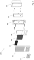
- FIG 2 shows an exemplary exploded view (200) of a wall mounted control panel 20.
- the front panel cover 42 including control buttons, 41 a sound or microphone and speaker unit 43, and a hardware implemented module representing the front processing unit 45 controlling an LED array 44 and the buttons 41.
- a second hardware implemented module representing the main processing and communication unit 47 which is housed in a wall integrated container 48 and mounted on a wall support 46.
Landscapes
- Engineering & Computer Science (AREA)
- Signal Processing (AREA)
- Computer Networks & Wireless Communication (AREA)
- Computer Security & Cryptography (AREA)
- Multimedia (AREA)
- Databases & Information Systems (AREA)
- Computer Graphics (AREA)
- Telephone Function (AREA)
- Selective Calling Equipment (AREA)
Claims (12)
- Un procédé pour accoupler une unité de contrôle (20) avec un deuxième dispositif, dans lequel :l'unité de contrôle (20) diffuse un signal de brève portée (25), et le deuxième dispositif (10) capte le signal de brève portée, dans lequel le dit signal de brève portée encode un code de sécurité;l'unité de contrôle et le deuxième dispositif envoient une requête de connexion (21, 23) à un serveur (30), chacune des requêtes de connexion provenant de l'unité de contrôle et du deuxième dispositif comprenant le the code de sécurité ou une séquence dérivée du code de sécurité,caractérisé en ce que le serveur (30) compares la requête de connexion (21) provenant de l'unité de contrôle (20) avec la requête de connexion (23) provenant du deuxième dispositif (10), et vérifie si and la requête (21) provenant de l'unité de contrôle (20) comprend le même code de sécurité ou séquence dérivée du code de sécurité que le code de sécurité reçu (23) du deuxième dispositif (10),et en ce que le serveur (30) accouple (88) l'unité de contrôle avec le deuxième dispositif, génère une clé sécurisée et transmet la clé sécurisée à l'unité de contrôle et au deuxième dispositif (90) si la vérification du code de sécurité ou de la séquence dérivée du code de sécurité a succès.
- Le procédé de la revendication précédente, dans lequel, après l'accouplement (88), l'unité de contrôle et le deuxième dispositif établissent une communication sécurisée, (92) en utilisant la clé sécurisée.
- Le procédé de la revendication 1, dans lequel signal de brève portée est un signal acoustique, un signal à ultrasons ou un signal lumineux.
- Le procédé de l'une quelconque des revendications 1 et 2, dans lequel le serveur compare si la requête de connexion (21) provenant de l'unité de contrôle et la requête de connexion (23) provenant du deuxième dispositif sont reçue dans un intervalle de retard prédéterminé (86).
- Un système (100) comprenant une unité de contrôle (20), un deuxième dispositif (10) et un serveur de accouplement (30), dans lequel l'unité de contrôle (20) est configurée pour émettre un signal de brève portée (25) qui encode un code de sécurité, et le deuxième dispositif est configuré pour recevoir le signal de brève portée,
l'unité de contrôle et le deuxième dispositif sont configurés pour envoyer chacun une requête de connexion (21, 23) au serveur de accouplement (30), chacune des requêtes de connexion provenant de l'unité de contrôle et du deuxième dispositif comprenant le the code de sécurité ou une séquence dérivée du code de sécurité, caractérisé en ce que le serveur (30) est configuré pour comparer la requête de connexion (21) provenant de l'unité de contrôle (20) avec la requête de connexion (23) provenant du deuxième dispositif (10), vérifier si and la requête (21) provenant de l'unité de contrôle (20) comprend le même code de sécurité ou séquence dérivée du code de sécurité que le code de sécurité reçu (23) du deuxième dispositif (10), et accoupler (88) l'unité de contrôle avec le deuxième dispositif, générer une clé sécurisée et transmettre la clé sécurisée à l'unité de contrôle et au deuxième dispositif (90) si la vérification du code de sécurité ou de la séquence dérivée du code de sécurité a succès. - Le système de la revendication précédente, dans lequel le deuxième dispositif est un dispositif mobile et/ou l'unité de contrôle est un dispositif de contrôle modulaire mural.
- Le système de la revendication 6, dans lequel le dispositif de contrôle modulaire mural comprend un module frontal remplaçable (42) et un module postérieur, dans lequel le module postérieur inclut un processeur (47), et le module frontal comprend des moyens de visualisation, par exemple une matrice de DEL (44).
- Le système de l'une quelconque des revendications 5-7, dans lequel ledit signal de brève portée est un signal acoustique, un signal à ultrasons ou un signal lumineux.
- Le système de l'une quelconque des revendications 5-8, dans un immeuble comprenant plusieurs appartements ou comprenant plusieurs familles, ou dans un hôtel comprenant plusieurs pièces.
- Un dispositif de stockage programmable avec des instructions de programme stockés pour causer l'exécution du procédé de la revendication 1 par un dispositif de contrôle programmable.
- Un serveur d'accouplement (30) pour accoupler des dispositifs, le serveur comprenant :Un module d'accouplement (83) opérable pour accoupler automatiquement les dispositifs en permettant le transfert de données entre les dispositifscaractérisé en ce quele module d'accouplement (83) est configuré pour comparer un premier code de sécurité (21) reçu d'une unité de contrôle (20) avec un deuxième code de sécurité (23) reçu d'un deuxième dispositif (10),le module d'accouplement étant configuré pour accoupler l'unité de contrôle avec le deuxième dispositif, générer une clé sécurisée et transmettre la clé sécurisée à l'unité de contrôle et au deuxième dispositif (90) si le premier code de sécurité et le deuxième code de sécurité reçu de l'unité de contrôle et du deuxième dispositif se correspondent.
- Le serveur d'accouplement (30) selon la revendication 11, dans lequel le serveur d'accouplement compare les clés sécurisées reçues dans un intervalle de temps prédéterminé ; si la réception d'une clé se situe au dehors d'une différence temporelle entre l'unité de contrôle et le deuxième dispositif prédéfinie ; le serveur d'accouplement termine la procédure d'accouplement sans accoupler le deuxième dispositif avec l'unité de contrôle et sans transmettre la deuxième clé de sécurité généré.
Applications Claiming Priority (1)
| Application Number | Priority Date | Filing Date | Title |
|---|---|---|---|
| CH11092019 | 2019-09-03 |
Publications (3)
| Publication Number | Publication Date |
|---|---|
| EP3790280A1 EP3790280A1 (fr) | 2021-03-10 |
| EP3790280C0 EP3790280C0 (fr) | 2023-11-15 |
| EP3790280B1 true EP3790280B1 (fr) | 2023-11-15 |
Family
ID=67909243
Family Applications (1)
| Application Number | Title | Priority Date | Filing Date |
|---|---|---|---|
| EP20188886.4A Active EP3790280B1 (fr) | 2019-09-03 | 2020-07-31 | Système et procédés d'appariement de dispositifs |
Country Status (2)
| Country | Link |
|---|---|
| EP (1) | EP3790280B1 (fr) |
| ES (1) | ES2969587T3 (fr) |
Families Citing this family (1)
| Publication number | Priority date | Publication date | Assignee | Title |
|---|---|---|---|---|
| CN113132963B (zh) * | 2021-04-20 | 2022-09-06 | 合肥星空物联信息科技有限公司 | 一种适用于智能跳绳的配对方法 |
Citations (6)
| Publication number | Priority date | Publication date | Assignee | Title |
|---|---|---|---|---|
| US4957362A (en) * | 1989-09-08 | 1990-09-18 | Environmental Research Institute Of Michigan | Method and apparatus for electro-optical phase detection |
| US6489984B1 (en) * | 1998-12-29 | 2002-12-03 | Kenneth C. Johnson | Pixel cross talk suppression in digital microprinters |
| EP1372040A2 (fr) * | 2002-06-11 | 2003-12-17 | ASML Netherlands B.V. | Appareil lithographique et méthode pour la fabrication d'un dispositif |
| US20060007446A1 (en) * | 2002-06-11 | 2006-01-12 | Asml Netherlands B.V. | Alignment system and method |
| US20140248019A1 (en) * | 2013-03-04 | 2014-09-04 | Rwth Aachen University | Electro-optical modulator based on carrier depletion or carrier accumulation in semiconductors with advanced electrode configuration |
| CN105049121A (zh) * | 2015-05-27 | 2015-11-11 | 西安空间无线电技术研究所 | 一种具有高交调失真抑制度的可调谐微波信号生成系统 |
Family Cites Families (12)
| Publication number | Priority date | Publication date | Assignee | Title |
|---|---|---|---|---|
| US20100227549A1 (en) * | 2009-03-04 | 2010-09-09 | Alan Kozlay | Apparatus and Method for Pairing Bluetooth Devices by Acoustic Pin Transfer |
| EP2510663A4 (fr) * | 2009-12-07 | 2015-02-25 | Ericsson Telefon Ab L M | Procédé et agencement pour permettre une lecture de contenu multimédia |
| US9628514B2 (en) * | 2011-11-10 | 2017-04-18 | Skype | Device association using an audio signal |
| US9288229B2 (en) * | 2011-11-10 | 2016-03-15 | Skype | Device association via video handshake |
| US9225937B2 (en) | 2013-10-18 | 2015-12-29 | Cisco Technology, Inc. | Ultrasound pairing signal control in a teleconferencing system |
| US9361541B2 (en) * | 2013-12-11 | 2016-06-07 | Samsung Electronics Co., Ltd. | Device pairing in a network |
| US9730001B2 (en) * | 2015-03-30 | 2017-08-08 | Vmware, Inc. | Proximity based authentication using bluetooth |
| US10187362B1 (en) * | 2015-06-22 | 2019-01-22 | Amazon Technologies, Inc. | Secure streamlined provisioning of remote access terminals |
| EP3332571B1 (fr) * | 2015-09-24 | 2019-05-22 | Square, Inc. | Jumelage assisté par le serveur pour communications sans fil |
| DE102018105113A1 (de) * | 2017-03-13 | 2018-09-13 | Panasonic Avionics Corporation | Passagiersitzpaarbildungssysteme und -verfahren |
| US11576677B2 (en) * | 2017-12-28 | 2023-02-14 | Cilag Gmbh International | Method of hub communication, processing, display, and cloud analytics |
| TWI670960B (zh) * | 2018-06-14 | 2019-09-01 | 笠眾實業有限公司 | 在公眾網路下進行驗證連線的車聯網系統及其連線方法 |
-
2020
- 2020-07-31 EP EP20188886.4A patent/EP3790280B1/fr active Active
- 2020-07-31 ES ES20188886T patent/ES2969587T3/es active Active
Patent Citations (6)
| Publication number | Priority date | Publication date | Assignee | Title |
|---|---|---|---|---|
| US4957362A (en) * | 1989-09-08 | 1990-09-18 | Environmental Research Institute Of Michigan | Method and apparatus for electro-optical phase detection |
| US6489984B1 (en) * | 1998-12-29 | 2002-12-03 | Kenneth C. Johnson | Pixel cross talk suppression in digital microprinters |
| EP1372040A2 (fr) * | 2002-06-11 | 2003-12-17 | ASML Netherlands B.V. | Appareil lithographique et méthode pour la fabrication d'un dispositif |
| US20060007446A1 (en) * | 2002-06-11 | 2006-01-12 | Asml Netherlands B.V. | Alignment system and method |
| US20140248019A1 (en) * | 2013-03-04 | 2014-09-04 | Rwth Aachen University | Electro-optical modulator based on carrier depletion or carrier accumulation in semiconductors with advanced electrode configuration |
| CN105049121A (zh) * | 2015-05-27 | 2015-11-11 | 西安空间无线电技术研究所 | 一种具有高交调失真抑制度的可调谐微波信号生成系统 |
Also Published As
| Publication number | Publication date |
|---|---|
| ES2969587T3 (es) | 2024-05-21 |
| EP3790280C0 (fr) | 2023-11-15 |
| EP3790280A1 (fr) | 2021-03-10 |
Similar Documents
| Publication | Publication Date | Title |
|---|---|---|
| Lei et al. | The insecurity of home digital voice assistants-vulnerabilities, attacks and countermeasures | |
| US20180295405A1 (en) | Portable Set Top Box and Internet of Things Controller with Laser Projection System | |
| US20190005751A1 (en) | Mobile device based authentication | |
| US20180241577A1 (en) | Proximity-Based Security | |
| JP4042723B2 (ja) | 通信システム、端末および通信方法 | |
| US11050737B2 (en) | Techniques for verifying user intent and securely configuring computing devices | |
| US20150319407A1 (en) | Intercom system utilizing wi-fi | |
| US20140141725A1 (en) | Wireless presentation system allowing automatic association and connection | |
| CN107211012B (zh) | 用于设备控制的接近检测的方法和装置 | |
| KR102250421B1 (ko) | Ai 음성인식 스피커 및 세대 내 설치된 네트워크 장치를 이용한 홈 네트워킹 방법, 이를 운용하기 위한 장치 및 시스템 | |
| US8195091B2 (en) | RF audio distribution system including IR presence detection | |
| EP3790280B1 (fr) | Système et procédés d'appariement de dispositifs | |
| CN120112811A (zh) | 设备定位 | |
| US9843683B2 (en) | Configuration method for sound collection system for meeting using terminals and server apparatus | |
| WO2018051144A1 (fr) | Procédé et système d'authentification d'un dispositif | |
| Al-Attar et al. | Smartphone-key: Hands-free two-factor authentication for voice-controlled devices using wi-fi location | |
| CN110803591B (zh) | 电梯楼层控制方法、系统以及相关设备 | |
| Fürst et al. | Leveraging physical locality to integrate smart appliances in non-residential buildings with ultrasound and bluetooth low energy | |
| Ji et al. | Authenticating smart home devices via home limited channels | |
| KR101649171B1 (ko) | 복수의 스피커를 제어하는 원격제어장치 | |
| JP6228585B2 (ja) | 音声機器のユーザにとっての音声体感を改善する方法 | |
| GB2595836A (en) | A method and system for authenticating a device | |
| JP6233664B2 (ja) | ドアホン親機および通信方法 | |
| JP6583833B2 (ja) | サーバー装置、および、通信方法 |
Legal Events
| Date | Code | Title | Description |
|---|---|---|---|
| PUAI | Public reference made under article 153(3) epc to a published international application that has entered the european phase |
Free format text: ORIGINAL CODE: 0009012 |
|
| STAA | Information on the status of an ep patent application or granted ep patent |
Free format text: STATUS: THE APPLICATION HAS BEEN PUBLISHED |
|
| AK | Designated contracting states |
Kind code of ref document: A1 Designated state(s): AL AT BE BG CH CY CZ DE DK EE ES FI FR GB GR HR HU IE IS IT LI LT LU LV MC MK MT NL NO PL PT RO RS SE SI SK SM TR |
|
| AX | Request for extension of the european patent |
Extension state: BA ME |
|
| STAA | Information on the status of an ep patent application or granted ep patent |
Free format text: STATUS: REQUEST FOR EXAMINATION WAS MADE |
|
| 17P | Request for examination filed |
Effective date: 20210909 |
|
| RBV | Designated contracting states (corrected) |
Designated state(s): AL AT BE BG CH CY CZ DE DK EE ES FI FR GB GR HR HU IE IS IT LI LT LU LV MC MK MT NL NO PL PT RO RS SE SI SK SM TR |
|
| REG | Reference to a national code |
Ref country code: DE Ref legal event code: R079 Free format text: PREVIOUS MAIN CLASS: H04N0021422000 Ipc: H04W0012500000 Ref country code: DE Ref legal event code: R079 Ref document number: 602020020983 Country of ref document: DE Free format text: PREVIOUS MAIN CLASS: H04N0021422000 Ipc: H04W0012500000 |
|
| RIC1 | Information provided on ipc code assigned before grant |
Ipc: H04N 21/41 20110101ALI20221107BHEP Ipc: H04N 21/258 20110101ALI20221107BHEP Ipc: H04N 21/4363 20110101ALI20221107BHEP Ipc: H04W 12/63 20210101ALI20221107BHEP Ipc: H04W 12/50 20210101AFI20221107BHEP |
|
| GRAP | Despatch of communication of intention to grant a patent |
Free format text: ORIGINAL CODE: EPIDOSNIGR1 |
|
| STAA | Information on the status of an ep patent application or granted ep patent |
Free format text: STATUS: GRANT OF PATENT IS INTENDED |
|
| INTG | Intention to grant announced |
Effective date: 20230112 |
|
| GRAJ | Information related to disapproval of communication of intention to grant by the applicant or resumption of examination proceedings by the epo deleted |
Free format text: ORIGINAL CODE: EPIDOSDIGR1 |
|
| STAA | Information on the status of an ep patent application or granted ep patent |
Free format text: STATUS: REQUEST FOR EXAMINATION WAS MADE |
|
| INTC | Intention to grant announced (deleted) | ||
| GRAP | Despatch of communication of intention to grant a patent |
Free format text: ORIGINAL CODE: EPIDOSNIGR1 |
|
| STAA | Information on the status of an ep patent application or granted ep patent |
Free format text: STATUS: GRANT OF PATENT IS INTENDED |
|
| INTG | Intention to grant announced |
Effective date: 20230619 |
|
| GRAS | Grant fee paid |
Free format text: ORIGINAL CODE: EPIDOSNIGR3 |
|
| GRAA | (expected) grant |
Free format text: ORIGINAL CODE: 0009210 |
|
| STAA | Information on the status of an ep patent application or granted ep patent |
Free format text: STATUS: THE PATENT HAS BEEN GRANTED |
|
| AK | Designated contracting states |
Kind code of ref document: B1 Designated state(s): AL AT BE BG CH CY CZ DE DK EE ES FI FR GB GR HR HU IE IS IT LI LT LU LV MC MK MT NL NO PL PT RO RS SE SI SK SM TR |
|
| REG | Reference to a national code |
Ref country code: CH Ref legal event code: EP Ref country code: GB Ref legal event code: FG4D |
|
| REG | Reference to a national code |
Ref country code: DE Ref legal event code: R096 Ref document number: 602020020983 Country of ref document: DE |
|
| REG | Reference to a national code |
Ref country code: IE Ref legal event code: FG4D |
|
| U01 | Request for unitary effect filed |
Effective date: 20231215 |
|
| U07 | Unitary effect registered |
Designated state(s): AT BE BG DE DK EE FI FR IT LT LU LV MT NL PT SE SI Effective date: 20240126 |
|
| PG25 | Lapsed in a contracting state [announced via postgrant information from national office to epo] |
Ref country code: GR Free format text: LAPSE BECAUSE OF FAILURE TO SUBMIT A TRANSLATION OF THE DESCRIPTION OR TO PAY THE FEE WITHIN THE PRESCRIBED TIME-LIMIT Effective date: 20240216 |
|
| PG25 | Lapsed in a contracting state [announced via postgrant information from national office to epo] |
Ref country code: IS Free format text: LAPSE BECAUSE OF FAILURE TO SUBMIT A TRANSLATION OF THE DESCRIPTION OR TO PAY THE FEE WITHIN THE PRESCRIBED TIME-LIMIT Effective date: 20240315 |
|
| PG25 | Lapsed in a contracting state [announced via postgrant information from national office to epo] |
Ref country code: IS Free format text: LAPSE BECAUSE OF FAILURE TO SUBMIT A TRANSLATION OF THE DESCRIPTION OR TO PAY THE FEE WITHIN THE PRESCRIBED TIME-LIMIT Effective date: 20240315 Ref country code: GR Free format text: LAPSE BECAUSE OF FAILURE TO SUBMIT A TRANSLATION OF THE DESCRIPTION OR TO PAY THE FEE WITHIN THE PRESCRIBED TIME-LIMIT Effective date: 20240216 |
|
| REG | Reference to a national code |
Ref country code: ES Ref legal event code: FG2A Ref document number: 2969587 Country of ref document: ES Kind code of ref document: T3 Effective date: 20240521 |
|
| PG25 | Lapsed in a contracting state [announced via postgrant information from national office to epo] |
Ref country code: RS Free format text: LAPSE BECAUSE OF FAILURE TO SUBMIT A TRANSLATION OF THE DESCRIPTION OR TO PAY THE FEE WITHIN THE PRESCRIBED TIME-LIMIT Effective date: 20231115 Ref country code: PL Free format text: LAPSE BECAUSE OF FAILURE TO SUBMIT A TRANSLATION OF THE DESCRIPTION OR TO PAY THE FEE WITHIN THE PRESCRIBED TIME-LIMIT Effective date: 20231115 Ref country code: NO Free format text: LAPSE BECAUSE OF FAILURE TO SUBMIT A TRANSLATION OF THE DESCRIPTION OR TO PAY THE FEE WITHIN THE PRESCRIBED TIME-LIMIT Effective date: 20240215 Ref country code: HR Free format text: LAPSE BECAUSE OF FAILURE TO SUBMIT A TRANSLATION OF THE DESCRIPTION OR TO PAY THE FEE WITHIN THE PRESCRIBED TIME-LIMIT Effective date: 20231115 |
|
| PG25 | Lapsed in a contracting state [announced via postgrant information from national office to epo] |
Ref country code: CZ Free format text: LAPSE BECAUSE OF FAILURE TO SUBMIT A TRANSLATION OF THE DESCRIPTION OR TO PAY THE FEE WITHIN THE PRESCRIBED TIME-LIMIT Effective date: 20231115 |
|
| PG25 | Lapsed in a contracting state [announced via postgrant information from national office to epo] |
Ref country code: SK Free format text: LAPSE BECAUSE OF FAILURE TO SUBMIT A TRANSLATION OF THE DESCRIPTION OR TO PAY THE FEE WITHIN THE PRESCRIBED TIME-LIMIT Effective date: 20231115 |
|
| PG25 | Lapsed in a contracting state [announced via postgrant information from national office to epo] |
Ref country code: SM Free format text: LAPSE BECAUSE OF FAILURE TO SUBMIT A TRANSLATION OF THE DESCRIPTION OR TO PAY THE FEE WITHIN THE PRESCRIBED TIME-LIMIT Effective date: 20231115 Ref country code: SK Free format text: LAPSE BECAUSE OF FAILURE TO SUBMIT A TRANSLATION OF THE DESCRIPTION OR TO PAY THE FEE WITHIN THE PRESCRIBED TIME-LIMIT Effective date: 20231115 Ref country code: RO Free format text: LAPSE BECAUSE OF FAILURE TO SUBMIT A TRANSLATION OF THE DESCRIPTION OR TO PAY THE FEE WITHIN THE PRESCRIBED TIME-LIMIT Effective date: 20231115 Ref country code: CZ Free format text: LAPSE BECAUSE OF FAILURE TO SUBMIT A TRANSLATION OF THE DESCRIPTION OR TO PAY THE FEE WITHIN THE PRESCRIBED TIME-LIMIT Effective date: 20231115 |
|
| REG | Reference to a national code |
Ref country code: DE Ref legal event code: R097 Ref document number: 602020020983 Country of ref document: DE |
|
| U20 | Renewal fee for the european patent with unitary effect paid |
Year of fee payment: 5 Effective date: 20240724 |
|
| PLBE | No opposition filed within time limit |
Free format text: ORIGINAL CODE: 0009261 |
|
| STAA | Information on the status of an ep patent application or granted ep patent |
Free format text: STATUS: NO OPPOSITION FILED WITHIN TIME LIMIT |
|
| 26N | No opposition filed |
Effective date: 20240819 |
|
| PG25 | Lapsed in a contracting state [announced via postgrant information from national office to epo] |
Ref country code: MC Free format text: LAPSE BECAUSE OF FAILURE TO SUBMIT A TRANSLATION OF THE DESCRIPTION OR TO PAY THE FEE WITHIN THE PRESCRIBED TIME-LIMIT Effective date: 20231115 |
|
| PG25 | Lapsed in a contracting state [announced via postgrant information from national office to epo] |
Ref country code: IE Free format text: LAPSE BECAUSE OF NON-PAYMENT OF DUE FEES Effective date: 20240731 |
|
| U20 | Renewal fee for the european patent with unitary effect paid |
Year of fee payment: 6 Effective date: 20250728 |
|
| PGFP | Annual fee paid to national office [announced via postgrant information from national office to epo] |
Ref country code: ES Payment date: 20250827 Year of fee payment: 6 |
|
| PGFP | Annual fee paid to national office [announced via postgrant information from national office to epo] |
Ref country code: GB Payment date: 20250722 Year of fee payment: 6 |
|
| PGFP | Annual fee paid to national office [announced via postgrant information from national office to epo] |
Ref country code: CH Payment date: 20250801 Year of fee payment: 6 |
|
| PG25 | Lapsed in a contracting state [announced via postgrant information from national office to epo] |
Ref country code: CY Free format text: LAPSE BECAUSE OF FAILURE TO SUBMIT A TRANSLATION OF THE DESCRIPTION OR TO PAY THE FEE WITHIN THE PRESCRIBED TIME-LIMIT; INVALID AB INITIO Effective date: 20200731 |
|
| PG25 | Lapsed in a contracting state [announced via postgrant information from national office to epo] |
Ref country code: HU Free format text: LAPSE BECAUSE OF FAILURE TO SUBMIT A TRANSLATION OF THE DESCRIPTION OR TO PAY THE FEE WITHIN THE PRESCRIBED TIME-LIMIT; INVALID AB INITIO Effective date: 20200731 |