EP3790334A1 - Procédé et appareil de transmission à multiplexage d'informations, et procédé et appareil de réception d'informations - Google Patents
Procédé et appareil de transmission à multiplexage d'informations, et procédé et appareil de réception d'informations Download PDFInfo
- Publication number
- EP3790334A1 EP3790334A1 EP18918339.5A EP18918339A EP3790334A1 EP 3790334 A1 EP3790334 A1 EP 3790334A1 EP 18918339 A EP18918339 A EP 18918339A EP 3790334 A1 EP3790334 A1 EP 3790334A1
- Authority
- EP
- European Patent Office
- Prior art keywords
- pusch
- uci
- multiplexing transmission
- selection
- selection criterion
- Prior art date
- Legal status (The legal status is an assumption and is not a legal conclusion. Google has not performed a legal analysis and makes no representation as to the accuracy of the status listed.)
- Granted
Links
Images


Classifications
-
- H—ELECTRICITY
- H04—ELECTRIC COMMUNICATION TECHNIQUE
- H04L—TRANSMISSION OF DIGITAL INFORMATION, e.g. TELEGRAPHIC COMMUNICATION
- H04L1/00—Arrangements for detecting or preventing errors in the information received
- H04L1/12—Arrangements for detecting or preventing errors in the information received by using return channel
- H04L1/16—Arrangements for detecting or preventing errors in the information received by using return channel in which the return channel carries supervisory signals, e.g. repetition request signals
- H04L1/18—Automatic repetition systems, e.g. Van Duuren systems
- H04L1/1829—Arrangements specially adapted for the receiver end
- H04L1/1864—ARQ related signaling
-
- H—ELECTRICITY
- H04—ELECTRIC COMMUNICATION TECHNIQUE
- H04W—WIRELESS COMMUNICATION NETWORKS
- H04W72/00—Local resource management
- H04W72/12—Wireless traffic scheduling
- H04W72/1263—Mapping of traffic onto schedule, e.g. scheduled allocation or multiplexing of flows
- H04W72/1268—Mapping of traffic onto schedule, e.g. scheduled allocation or multiplexing of flows of uplink data flows
-
- H—ELECTRICITY
- H04—ELECTRIC COMMUNICATION TECHNIQUE
- H04L—TRANSMISSION OF DIGITAL INFORMATION, e.g. TELEGRAPHIC COMMUNICATION
- H04L5/00—Arrangements affording multiple use of the transmission path
- H04L5/0001—Arrangements for dividing the transmission path
- H04L5/0003—Two-dimensional division
- H04L5/0005—Time-frequency
- H04L5/0007—Time-frequency the frequencies being orthogonal, e.g. OFDM(A) or DMT
-
- H—ELECTRICITY
- H04—ELECTRIC COMMUNICATION TECHNIQUE
- H04L—TRANSMISSION OF DIGITAL INFORMATION, e.g. TELEGRAPHIC COMMUNICATION
- H04L5/00—Arrangements affording multiple use of the transmission path
- H04L5/003—Arrangements for allocating sub-channels of the transmission path
- H04L5/0044—Allocation of payload; Allocation of data channels, e.g. PDSCH or PUSCH
-
- H—ELECTRICITY
- H04—ELECTRIC COMMUNICATION TECHNIQUE
- H04L—TRANSMISSION OF DIGITAL INFORMATION, e.g. TELEGRAPHIC COMMUNICATION
- H04L5/00—Arrangements affording multiple use of the transmission path
- H04L5/003—Arrangements for allocating sub-channels of the transmission path
- H04L5/0053—Allocation of signalling, i.e. of overhead other than pilot signals
-
- H—ELECTRICITY
- H04—ELECTRIC COMMUNICATION TECHNIQUE
- H04L—TRANSMISSION OF DIGITAL INFORMATION, e.g. TELEGRAPHIC COMMUNICATION
- H04L5/00—Arrangements affording multiple use of the transmission path
- H04L5/0091—Signalling for the administration of the divided path, e.g. signalling of configuration information
- H04L5/0094—Indication of how sub-channels of the path are allocated
-
- H—ELECTRICITY
- H04—ELECTRIC COMMUNICATION TECHNIQUE
- H04W—WIRELESS COMMUNICATION NETWORKS
- H04W72/00—Local resource management
- H04W72/04—Wireless resource allocation
- H04W72/044—Wireless resource allocation based on the type of the allocated resource
- H04W72/0446—Resources in time domain, e.g. slots or frames
-
- H—ELECTRICITY
- H04—ELECTRIC COMMUNICATION TECHNIQUE
- H04W—WIRELESS COMMUNICATION NETWORKS
- H04W72/00—Local resource management
- H04W72/04—Wireless resource allocation
- H04W72/044—Wireless resource allocation based on the type of the allocated resource
- H04W72/0453—Resources in frequency domain, e.g. a carrier in FDMA
-
- H—ELECTRICITY
- H04—ELECTRIC COMMUNICATION TECHNIQUE
- H04W—WIRELESS COMMUNICATION NETWORKS
- H04W72/00—Local resource management
- H04W72/20—Control channels or signalling for resource management
-
- H—ELECTRICITY
- H04—ELECTRIC COMMUNICATION TECHNIQUE
- H04W—WIRELESS COMMUNICATION NETWORKS
- H04W72/00—Local resource management
- H04W72/20—Control channels or signalling for resource management
- H04W72/21—Control channels or signalling for resource management in the uplink direction of a wireless link, i.e. towards the network
-
- H—ELECTRICITY
- H04—ELECTRIC COMMUNICATION TECHNIQUE
- H04W—WIRELESS COMMUNICATION NETWORKS
- H04W72/00—Local resource management
- H04W72/20—Control channels or signalling for resource management
- H04W72/23—Control channels or signalling for resource management in the downlink direction of a wireless link, i.e. towards a terminal
-
- H—ELECTRICITY
- H04—ELECTRIC COMMUNICATION TECHNIQUE
- H04L—TRANSMISSION OF DIGITAL INFORMATION, e.g. TELEGRAPHIC COMMUNICATION
- H04L5/00—Arrangements affording multiple use of the transmission path
- H04L5/003—Arrangements for allocating sub-channels of the transmission path
- H04L5/0053—Allocation of signalling, i.e. of overhead other than pilot signals
- H04L5/0055—Physical resource allocation for ACK/NACK
-
- H—ELECTRICITY
- H04—ELECTRIC COMMUNICATION TECHNIQUE
- H04L—TRANSMISSION OF DIGITAL INFORMATION, e.g. TELEGRAPHIC COMMUNICATION
- H04L5/00—Arrangements affording multiple use of the transmission path
- H04L5/003—Arrangements for allocating sub-channels of the transmission path
- H04L5/0053—Allocation of signalling, i.e. of overhead other than pilot signals
- H04L5/0057—Physical resource allocation for CQI
Definitions
- the disclosure relates to the technical field of communications, in particular to a method and apparatus for multiplexing transmission of information, a method and apparatus for receiving information, user equipment, a base station and a computer-readable storage medium.
- a new generation of novel Internet applications put forward higher requirements for a wireless communication technology, driving the wireless communication technology to evolve continuously to meet the needs of the applications.
- a cellular mobile communication technology is in the evolution stage of a new generation of technology.
- how to design improved uplink transmission to meet the needs of the system is an important subject.
- NR New Radio
- Different service types have different requirements for the wireless communication technology.
- eMBB enhanced Mobile Broad Band
- URLLC Ultra Reliable Low Latency Communication
- mMTC massive Machine Type Communication
- LCHs Logical Channels
- MAC Media Access Control
- Uplink control information includes a Hybrid Automatic Repeat reQuest (HARQ) indicator, a Scheduling Request (SR) and a Channel Status Indicator (CSI).
- HARQ Hybrid Automatic Repeat reQuest
- SR Scheduling Request
- CSI Channel Status Indicator
- the SR may be used by user equipment (UE) to apply to a base station for uplink resource scheduling.
- UE user equipment
- same UE may be configured with a variety of different SRs, each of which corresponds to one or more LCHs.
- the UCI can be transmitted through a physical uplink control channel (PUCCH).
- PUCCH physical uplink control channel
- UE may discard the transmission on the PUCCH and transmit the UCI including the HARQ indicator and the CSI through the PUSCH together with the uplink data.
- PAPR Peak to Average Power Ratio
- MPR Maximum Power Reduction
- Radio Access Network (RAN) 1 it was decided that when a PUCCH and a PUSCH were overlapped only partially in time-domain and had different starting symbols, the PUCCH and the PUSCH would also conduct multiplexing transmission when they met given timing requirements.
- UE may give up the transmission on the PUCCH, and the UCI transmitted on the PUCCH and content transmitted on the PUSCH may be multiplexed and then transmitted on the PUSCH.
- a method for multiplexing transmission of information and apparatus a method for receiving information and apparatus, user equipment (UE), a base station and a computer-readable storage medium are provided, in order to select a suitable PUSCH for multiplexing transmission when a Physical Uplink Control Channel (PUCCH) and a plurality of different Physical Uplink Shared Channels (PUSCHs) have an overlapping portion in time-domain.
- PUCCH Physical Uplink Control Channel
- PUSCHs Physical Uplink Shared Channels
- a method for multiplexing transmission of information is provided.
- the method may be applied to UE and may include:
- the selecting the PUSCH for the multiplexing transmission of the UCI carried in the PUCCH based on the selection criterion may include: taking a PUSCH with an earliest starting position or an earliest ending position in time-domain as the PUSCH for the multiplexing transmission of the UCI.
- the selecting the PUSCH for the multiplexing transmission of the UCI carried in the PUCCH based on the selection criterion may include: when a PUSCH of the plurality of PUSCHs is a PUSCH for uplink transmission based on a downlink dynamic scheduling (DL grant) and a PUSCH of the plurality of PUSCHs is a PUSCH for uplink transmission based on configured grant, taking the PUSCH for uplink transmission based on the DL grant as the PUSCH for the multiplexing transmission of the UCI.
- DL grant downlink dynamic scheduling
- the selecting the PUSCH for the multiplexing transmission of the UCI carried in the PUCCH based on the selection criterion may include: selecting a PUSCH with a maximum number of symbols in time-domain overlapped with the PUCCH as the PUSCH for the multiplexing transmission of the UCI.
- the selecting the PUSCH for the multiplexing transmission of the UCI carried in the PUCCH based on the selection criterion may include: selecting a PUSCH with a maximum number of resource units in an occupied time-frequency resource as the PUSCH for the multiplexing transmission of the UCI.
- the selecting the PUSCH for the multiplexing transmission of the UCI carried in the PUCCH based on the selection criterion may include:
- the method may further include:
- a method for receiving information is provided.
- the method may be applied to a base station and may include:
- the method may further include:
- an apparatus for multiplexing transmission of information may be applied to UE and may include:
- the selection module may include: a first selection submodule, configured to take a PUSCH with an earliest starting position or an earliest ending position in time-domain as the PUSCH for the multiplexing transmission of the UCI.
- the selection module may include: a second selection submodule, configured to, when a PUSCH of the plurality of PUSCHs is a PUSCH for uplink transmission based on a downlink dynamic scheduling (DL grant) and a PUSCH of the plurality of PUSCHs is a PUSCH for uplink transmission based on configured grant, take the PUSCH for uplink transmission based on the DL grant as the PUSCH for the multiplexing transmission of the UCI.
- a second selection submodule configured to, when a PUSCH of the plurality of PUSCHs is a PUSCH for uplink transmission based on a downlink dynamic scheduling (DL grant) and a PUSCH of the plurality of PUSCHs is a PUSCH for uplink transmission based on configured grant, take the PUSCH for uplink transmission based on the DL grant as the PUSCH for the multiplexing transmission of the UCI.
- DL grant downlink dynamic scheduling
- the selection module may include: a third selection submodule, configured to select a PUSCH with a maximum number of symbols in time-domain overlapped with the PUCCH as the PUSCH for the multiplexing transmission of the UCI.
- the selection module may include: a fourth selection submodule, configured to select a PUSCH with a maximum number of resource units in an occupied time-frequency resource as the PUSCH for the multiplexing transmission of the UCI.
- the selection module may include:
- the apparatus may further include:
- an apparatus for receiving information and the apparatus is applied to a base station, and may include:
- the apparatus may further include:
- the UE may include:
- a base station may include:
- a computer-readable storage medium storing computer instructions thereon. Operations of the method for multiplexing transmission of information may be implemented when the instructions are executed by a processor.
- a computer-readable storage medium storing computer instructions thereon. Operations of the method for receiving information may be implemented when the instructions are executed by a processor.
- a PUSCH for multiplexing transmission of UCI carried in the PUCCH may be selected based on a selection criterion.
- the transmission may be performed by multiplexing the UCI and the transmission content of the selected PUSCH in the selected PUSCH, so that a suitable PUSCH can be selected for the multiplexing transmission.
- a PUSCH for the multiplexing transmission of the UCI may be determined based on the selection criterion, and the UCI may be received from the determined PUSCH, thereby receiving the UCI.
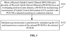
- FIG. 1 is a flow diagram of a method for multiplexing transmission of information as shown in an exemplary embodiment of the disclosure. The embodiment is described from a User Equipment (UE) side. As shown in FIG. 1 , the method for multiplexing transmission of information includes the following operations.
- UE User Equipment
- a PUSCH for multiplexing transmission of Uplink Control Information (UCI) carried in the PUCCH is selected based on a selection criterion.
- UCI Uplink Control Information
- the method may further include: a selection criterion sent by a base station is received, and the selection criterion may also be agreed with a base station.
- the selecting the PUSCH for the multiplexing transmission of the UCI carried in the PUCCH based on the selection criterion may include, but is not limited to, any of the following situations.
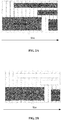
- Scenario 1 a PUSCH with an earliest starting position or an earliest ending position in time-domain is taken as the PUSCH for the multiplexing transmission of the UCI.
- PUCCH1 in FIG 2A carries UCI1
- PUCCH2 carries UCI2
- PUSCH1 carries data 1
- PUSCH2 carries data 2. Since a starting position of PUSCH1 in time-domain is earlier than that of PUSCH2, PUSCH1 is selected as the PUSCH for the multiplexing transmission of the UCI.
- Both the UCI of PUCCH1 and PUCCH2 are multiplexed in the PUSCH1.
- UCI1, UCI2 and data 1 may be transmitted by multiplexing in the PUSCH1.
- Scenario 2 when one PUSCH of the plurality of PUSCHs for uplink transmission is based on the DL grant and another PUSCH for uplink transmission is based on configured grant, a PUSCH for uplink transmission based on downlink dynamic scheduling (DL grant) is taken as the PUSCH for the multiplexing transmission of the UCI.
- DL grant downlink dynamic scheduling
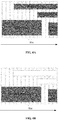
- PUCCH1 in FIG 3A carries UCI1
- PUCCH2 carries UCI2
- PUSCH1 carries data 1
- PUSCH2 carries data 2
- PUSCH1 is a PUSCH for uplink transmission based on DL grant
- PUSCH2 is a PUSCH for uplink transmission based on configured grant.
- PUSCH1 may be selected as the PUSCH for the multiplexing transmission of the UCI.
- Both PUCCH1 and PUCCH2 may conduct multiplexing transmission of the UCI through PUSCH1.
- FIG. 3B multiplexing transmission of UCI1, UCI2 and data 1 may be conducted through PUSCH1.
- a PUSCH with the maximum number of symbols in time-domain overlapped with the PUCCH is selected as the PUSCH for the multiplexing transmission of the UCI.
- PUCCH1 in FIG 4A carries UCI1
- PUCCH2 carries UCI2
- PUSCH1 carries data 1
- PUSCH2 carries data 2.
- the number of overlapped symbols in time-domain of PUCCH1 and PUSCH1 is relatively large, therefore, UCI1 and data 1 are transmitted by multiplexing in PUSCH1.
- the number of overlapped symbols in time-domain of PUCCH2 and PUSCH2 is relatively large, thus UCI2 and data 2 are transmitted by multiplexing in PUSCH2.
- UCI1 and data 1 may be transmitted by multiplexing in PUSCH1
- UCI2 and data 2 may be transmitted by multiplexing in PUSCH2.
- a PUSCH with the maximum number of occupied resource units in a time-frequency resource is selected as the PUSCH for the multiplexing transmission of the UCI.
- PUCCH1 in FIG 5A carries UCI1
- PUCCH2 carries UCI2
- PUSCH1 carries data 1
- PUSCH2 carries data 2. Since the number of the resource units in time-domain resource occupied by PUSCH1 is relatively large, PUSCH1 is selected as the PUSCH for the multiplexing transmission of the UCI.
- UCI1, UCI2 and data 1 may be transmitted by multiplexing in PUSCH1.
- a corresponding selection criterion is determined according to a type of the UCI and pre-stored corresponding relationships between types of UCI and different selection criteria.
- a PUSCH is selected as the PUSCH for the multiplexing transmission of the UCI according to the determined selection criterion.
- the method may further include: the corresponding relationships between types of the UCI and the different selection criteria sent by a base station are received, or the corresponding relationships between types of the UCI and the different selection criteria may be agreed with a base station.
- the PUSCH namely PUSCH2
- the PUSCH with the earliest starting position in time-domain
- a report message that is a channel Status Indicator (CSI) the PUSCH, namely PUSCH1, with the maximum number of occupied resource units in the time-frequency resource may be selected as the PUSCH for the multiplexing transmission.
- HARQ and data 2 may be transmitted by multiplexing in PUSCH2, and CSI and data 1 may be transmitted by multiplexing in PUSCH1.
- multiplexing transmission is performed by multiplexing the UCI and transmission content of the selected PUSCH in the selected PUSCH.
- the multiplexing transmission may be performed by multiplexing the UCI and the transmission content of the selected PUSCH in the selected PUSCH.
- a PUSCH for multiplexing transmission of UCI carried in the PUCCH may be selected based on a selection criterion.
- the selected PUSCH may be used for performing the transmission by multiplexing the UCI and the transmission content of the selected PUSCH in the selected PUSCH, and thereby a suitable PUSCH is selected for the multiplexing transmission.
- FIG. 7 is a flow diagram of a method for receiving information as shown in an exemplary embodiment of the disclosure. The embodiment is described from a base station side. As shown in FIG. 7 , the method includes the operations as below.
- a PUSCH for multiplexing transmission of UCI is determined based on a selection criterion.
- the method may further include: a selection criterion is determined and sent to UE, or the selection criterion can also be agreed with the UE.
- the PUSCH for the multiplexing transmission of the UCI can be determined based on the selection criterion.
- the UCI is received from the determined PUSCH.
- a PUSCH for multiplexing transmission of UCI may be determined based on a selection criterion, and the UCI may be received from the determined PUSCH, thereby receiving the UCI.
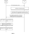
- FIG. 8 is a signaling flow diagram of the method for receiving information as shown in an exemplary embodiment of the disclosure. The embodiment is described from the angle of interaction between a base station and UE. As shown in FIG. 8 , the method includes following operations.
- the base station determines a selection criterion and sends the selection criterion to the UE.
- the UE receives the selection criterion.
- the UE selects a PUSCH for multiplexing transmission of UCI carried in the PUCCH according to the received selection criterion.
- the UE performs the transmission by multiplexing the UCI and transmission content of the selected PUSCH in the selected PUSCH.
- the base station receives the plurality of PUSCH transmissions.
- the base station determines the PUSCH for the multiplexing transmission of the UCI according to the determined selection criterion.
- the base station receives the UCI from the determined PUSCH.
- the UE can select a suitable PUSCH for the multiplexing transmission, and thus the base station can determine the PUSCH for the multiplexing transmission of UCI and receives the UCI from the determined PUSCH.
- FIG. 9 is a block diagram of an apparatus for multiplexing transmission of information as shown in an exemplary embodiment of the disclosure.
- the apparatus is arranged in UE.
- the apparatus includes a selection module 91 and a transmission module 92.
- the selection module 91 is configured to select a PUSCH for multiplexing transmission of UCI carried in a PUCCH based on a selection criterion when the PUCCH and a plurality of PUSCHs have an overlapping portion in time-domain.
- the transmission module 92 is configured to perform the transmission by multiplexing the UCI and transmission content of the selected PUSCH in the PUSCH selected by the selection module 91.
- the transmission may be performed by multiplexing the UCI and the transmission content of the selected PUSCH in the selected PUSCH.
- a PUSCH for multiplexing transmission of UCI carried in the PUCCH may be selected based on a selection criterion, and the transmission may be performed by multiplexing the UCI and the transmission content of the selected PUSCH in the selected PUSCH.
- FIG. 10 is a block diagram of another apparatus for multiplexing transmission of information as shown in an exemplary embodiment of the disclosure.
- the selection module 91 may include: a first selection submodule 911.
- the first selection submodule 911 is configured to take a PUSCH with an earliest starting position or an earliest ending position in time-domain as the PUSCH for the multiplexing transmission of the UCI.
- PUCCH1 in FIG. 2A carries UCI1
- PUCCH2 carries UCI2
- PUSCH1 carries data 1
- PUSCH2 carries data 2. Since a starting position of PUSCH1 in the time-domain is earlier than that of PUSCH2, PUSCH1 may be selected as the PUSCH for the multiplexing transmission of the UCI. Both the UCI of PUCCH1 and PUCCH2 are multiplexed in the PUSCH1. As shown in FIG. 2B , UCI1, UCI2 and data 1 may be transmitted by multiplexing in the PUSCH1.
- a PUSCH with an earliest starting position or an earliest ending position in time-domain is adopted as the PUSCH for the multiplexing transmission of the UCI, which provides a condition for subsequent multiplexing transmission of the UCI in the selected PUSCH.
- the implementation is simple.
- FIG. 11 is a block diagram of yet another apparatus for multiplexing transmission of information as shown in an exemplary embodiment of the disclosure.
- the selection module 91 may include a second selection submodule 912.
- the second selection submodule 912 is configured to take a PUSCH for uplink transmission based on DL grant as the PUSCH for the multiplexing transmission of the UCI when a PUSCH of the plurality of PUSCHs is a PUSCH for uplink transmission based on the DL grant and a PUSCH of the plurality of PUSCHs is a PUSCH for uplink transmission based on configured grant.
- a PUSCH for uplink transmission based on DL grant is adopted as the PUSCH for multiplexing transmission of UCI, which provides a condition for subsequent multiplexing transmission of the UCI in the selected PUSCH.
- Such implementation is simple.
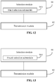
- FIG. 12 is a block diagram of yet another apparatus for multiplexing transmission of information as shown in an exemplary embodiment of the disclosure.
- the selection module 91 may include a third selection submodule 913.
- the third selection submodule 913 is configured to select a PUSCH with the maximum number of symbols in time-domain overlapped with the PUCCH as the PUSCH for the multiplexing transmission of the UCI.
- a PUSCH with the maximum number of symbols in time-domain overlapped with the PUCCH is selected as the PUSCH for multiplexing transmission of UCI, which provides a condition for subsequent multiplexing transmission of the UCI in the selected PUSCH,
- the implementation is simple.
- FIG. 13 is a block diagram of yet another apparatus for multiplexing transmission of information as shown in an exemplary embodiment of the disclosure.
- the selection module 91 may include a fourth selection submodule 914.
- the fourth selection submodule 914 is configured to select a PUSCH with the maximum number of resource units in an occupied time-frequency resource as the PUSCH for the multiplexing transmission of the UCI.
- a PUSCH with the maximum number of resource units in the occupied time-frequency resource is selected as the PUSCH for multiplexing transmission of UCI, which provides a condition for subsequent multiplexing transmission of the UCI in the selected PUSCH,
- the implementation is simple.
- FIG. 14 is a block diagram of yet another apparatus for multiplexing transmission of information as shown in an exemplary embodiment of the disclosure.
- the selection module 91 may include a determining submodule 915 and a fifth selection submodule 916.
- the determining submodule 915 is configured to determine a corresponding selection criterion according to a type of the UCI and pre-stored corresponding relationships between types of UCI and different selection criteria;
- the fifth determining submodule 916 is configured to select a PUSCH as the PUSCH for the multiplexing transmission of the UCI based on the selection criterion determined by the determining submodule 915.
- a PUSCH may be selected as the PUSCH for multiplexing transmission of UCI according to a determined selection criterion, which provides a condition for subsequent multiplexing transmission of the UCI in the selected PUSCH,
- a determined selection criterion which provides a condition for subsequent multiplexing transmission of the UCI in the selected PUSCH
- FIG. 15 is a block diagram of yet another apparatus for multiplexing transmission of information as shown in an exemplary embodiment of the disclosure. As shown in FIG. 15 , on the basis of the embodiment shown in FIG. 9 above, the apparatus may further include a receiving module 93 or an agreeing module 94.
- the receiving module 93 is configured to receive the selection criterion or the corresponding relationships between types of UCI and different selection criteria from a base station.
- the agreeing module 94 is configured to agree the selection criterion or the corresponding relationships between types of UCI and different selection criteria with the base station.
- the selection criterion may be determined or agreed, which provides a condition for subsequent selection of the PUSCH for the multiplexing transmission of the UCI based on the selection criterion.
- FIG. 16 is a block diagram of an apparatus for receiving information as shown in an exemplary embodiment of the disclosure.
- the apparatus can be located in a base station. As shown in FIG. 16 , the apparatus includes:
- a PUSCH for multiplexing transmission of UCI may be determined based on a selection criterion, and the UCI may be received from the determined PUSCH, thereby receiving the UCI.
- FIG. 17 is a block diagram of another apparatus for receiving information as shown in an exemplary embodiment of the disclosure. As shown in FIG. 17 , on the basis of the embodiment shown in FIG. 16 above, the apparatus may further include a first determining and sending module 164, a second determining and sending module 165 or an agreeing module 166.
- the first determining and sending module 164 is configured to determine the selection criterion and send the selection criterion to UE.
- the second determining and sending module 165 is configured to determine corresponding relationships between the type of the UCI and different selection criteria and send the corresponding relationships between types of UCI and different selection criteria to the UE.
- the agreeing module 166 is configured to agree the selection criterion or the corresponding relationships between types of UCI and different selection criteria with the UE.
- a selection criterion may be determined and sent to UE or may be agreed with the UE, which enables the UE to select a PUSCH for multiplexing transmission of UCI based on the selection criterion.
- FIG. 18 is a block diagram of an apparatus suitable for multiplexing transmission of information as shown in an exemplary embodiment of the disclosure.
- the apparatus 1800 may be user equipment such as a mobile phone, a computer, a digital broadcasting terminal, a message transceiver, a game console, tablet equipment, medical equipment, fitness equipment, and a personal digital assistant.
- the apparatus 1800 may include one or more of the following components: a processing component 1802, a memory 1804, a power component 1806, a multimedia component 1808, an audio component 1810, an Input/Output (I/O) interface 1812, a sensor component 1814, and a communication component 1816.
- a processing component 1802 a memory 1804, a power component 1806, a multimedia component 1808, an audio component 1810, an Input/Output (I/O) interface 1812, a sensor component 1814, and a communication component 1816.
- a processing component 1802 a memory 1804, a power component 1806, a multimedia component 1808, an audio component 1810, an Input/Output (I/O) interface 1812, a sensor component 1814, and a communication component 1816.
- I/O Input/Output
- the processing component 1802 generally controls overall operations of the apparatus 1800, such as operations related to displaying, telephone calls, data communications, camera operations, and recording operations.
- the processing component 1802 may include one or more processors 1820 to execute instructions, so as to complete all or part of the operations of the method described above.
- the processing component 1802 may include one or more modules to facilitate the interaction between the processing component 1802 and other components.
- the processing component 1802 may include a multimedia module to facilitate the interaction between the multimedia component 1808 and the processing component 1802.
- One of the processors 1820 of the processing component 1802 may be configured to:
- the memory 1804 is configured to store various types of data to support the operation of the apparatus 1800. Examples of such data include instructions for any application program or method operated on the apparatus 1800, contact data, phone book data, messages, pictures, videos, and the like.
- the memory 1804 may be implemented by any type of volatile or non-volatile storage devices or a combination thereof, such as a Static Random Access Memory (SRAM), an Electrically Erasable Programmable Read-Only Memory (EEPROM), a Programming Read-Only Memory (EPROM), a Programmable Read-Only Memory (PROM), a Read-Only Memory (ROM), a magnetic memory, a flash memory, a magnetic disk or an optical disk.
- SRAM Static Random Access Memory
- EEPROM Electrically Erasable Programmable Read-Only Memory
- EPROM Programming Read-Only Memory
- PROM Programmable Read-Only Memory
- ROM Read-Only Memory
- the power component 1806 is configured to provide power for various components of the apparatus 1800.
- the power component 1806 may include a power management system, one or more power supplies, and other components associated with generating, managing, and distributing power for the apparatus 1800.
- the multimedia component 1808 may include a screen providing an output interface between the apparatus 1800 and a user.
- the screen may include an LCD and a TP. If it includes the TP, the screen may be implemented as a touch screen to receive an input signal from a user.
- the TP includes one or more touch sensors to sense touch, swipe, and gestures on the TP. The touch sensors may not only sense a boundary of a touch or swipe action, but also detect a time of duration and a pressure associated with the touch or swipe action.
- the multimedia component 1808 includes a front camera and/or a rear camera. The front camera and the rear camera may receive external multimedia data while the apparatus 1800 is in an operation mode, such as a photographing mode or a video mode. Each of the front camera and rear camera may be a fixed optical lens system or may have focal lengths and optical zoom capabilities.
- the audio component 1810 is configured to output and/or input audio signals.
- the audio component 1810 includes a microphone (MIC), and the microphone is configured to receive an external audio signal when the apparatus 1800 is in an operation mode, such as a calling mode, a recording mode, and a voice identification mode.
- the received audio signals may be further stored in the memory 1804 or transmitted via the communication component 1816.
- the audio component 1810 may further include a speaker to output audio signals.
- the I/O interface 1812 is configured to provide an interface between the processing component 1802 and peripheral interface modules, which may be keyboards, click wheels, buttons, etc. These buttons may include, but are not limited to: a home button, a volume button, a start button, and a lock button.
- the sensor component 1814 may include one or more sensors configured to provide various aspects of state assessment for the apparatus 1800.
- the sensor component 1814 may detect an on/off status of the apparatus 1800, and relative positioning of components.
- the component is a display and a keypad of the apparatus 1800.
- the sensor component 1814 may also detect a change in position of the apparatus 1800 or a component of the apparatus 1800, presence or absence of user contact with the apparatus 1800, an orientation or an acceleration/deceleration of the apparatus 1800, and a change in temperature of the apparatus 1800.
- the sensor component 1814 may include a proximity sensor configured to detect the presence of objects nearby without any physical contact.
- the sensor component 1814 may also include light sensors, such as CMOS or CCD image sensors, for use in imaging applications.
- the sensor component 1814 may also include an acceleration sensor, a gyroscope sensor, a magnetic sensor, a pressure sensor, or a temperature sensor.
- the communication component 1816 is configured to facilitate wired or wireless communications between the apparatus 1800 and other devices.
- the apparatus 1800 may access a wireless network based on a communication standard, such as WiFi, 2G or 6G, or a combination thereof.
- the communication component 1816 receives a broadcast signal or broadcast related information from an external broadcast management system via a broadcast channel.
- the communication component 1816 further includes a Near Field Communication (NFC) module to promote short-range communications.
- NFC Near Field Communication
- the NFC module may be implemented based on a Radio Frequency Identification (RFID) technology, an Infrared Data Association (IrDA), an Ultra-Wide Band (UWB) technology, a Bluetooth (BT) technology and other technologies.
- RFID Radio Frequency Identification
- IrDA Infrared Data Association
- UWB Ultra-Wide Band
- BT Bluetooth
- the apparatus 1800 may be implemented by one or more Application-Specific Integrated Circuits (ASICs), Digital Signal Processors (DSPs), Digital Signal Processing Devices (DSPDs), Programmable Logic Devices (PLDs), Field Programmable Gate Arrays (FPGAs), controllers, microcontrollers, microprocessors, or other electronic components to perform the above method.
- ASICs Application-Specific Integrated Circuits
- DSPs Digital Signal Processors
- DSPDs Digital Signal Processing Devices
- PLDs Programmable Logic Devices
- FPGAs Field Programmable Gate Arrays
- controllers microcontrollers, microprocessors, or other electronic components to perform the above method.
- a non-transitory computer-readable storage medium storing instructions, such as the memory 1804 storing instructions.
- the above instructions may be executed by the processor 1820 of the apparatus 1800 to complete the foregoing method.
- the non-transitory computer-readable storage medium may be a Read Only Memory (ROM), a Random Access Memory (RAM), a CD-ROM, a magnetic tape, a floppy disc, an optical data storage device, and the like.
- FIG. 19 is a block diagram illustrating an apparatus suitable for multiplexing transmission of information according to an exemplary embodiment.
- the apparatus 1900 may be provided as a base station.
- the apparatus 1900 includes a processing component 1922, a wireless transmitting/receiving component 1924, an antenna component 1926 and a specific signal processing part of a wireless interface.
- the processing component 1922 may further include one or more processors.
- One of the processors in the processing component 1922 may be configured to:
- a non-transitory computer-readable storage medium storing instructions is further provided.
- the above instructions may be executed by the processing component 1922 of the apparatus 1900 to implement the above method for receiving information.
- the non-transitory computer-readable storage medium may be a Read Only Memory (ROM), a Random Access Memory (RAM), a CD-ROM, a magnetic tape, a floppy disc, an optical data storage device, and the like.
- the apparatus embodiments described above are merely illustrative.
- the units illustrated as separate elements may or may not be physically separate.
- the elements shown as units may or may not be physical units, i.e., may be arranged in one place, or may be distributed in a plurality of network units. Some or all of the modules may be selected according to actual needs to achieve the solutions of the embodiments. Those ordinarily skilled in the art would understand and practice without involving any inventive effort.
Landscapes
- Engineering & Computer Science (AREA)
- Signal Processing (AREA)
- Computer Networks & Wireless Communication (AREA)
- Mobile Radio Communication Systems (AREA)
Applications Claiming Priority (1)
| Application Number | Priority Date | Filing Date | Title |
|---|---|---|---|
| PCT/CN2018/086357 WO2019213907A1 (fr) | 2018-05-10 | 2018-05-10 | Procédé et appareil de transmission à multiplexage d'informations, et procédé et appareil de réception d'informations |
Publications (3)
| Publication Number | Publication Date |
|---|---|
| EP3790334A1 true EP3790334A1 (fr) | 2021-03-10 |
| EP3790334A4 EP3790334A4 (fr) | 2021-05-05 |
| EP3790334B1 EP3790334B1 (fr) | 2023-10-18 |
Family
ID=63841448
Family Applications (1)
| Application Number | Title | Priority Date | Filing Date |
|---|---|---|---|
| EP18918339.5A Active EP3790334B1 (fr) | 2018-05-10 | 2018-05-10 | Procédé et appareil de transmission à multiplexage d'informations, et procédé et appareil de réception d'informations |
Country Status (11)
| Country | Link |
|---|---|
| US (1) | US11985667B2 (fr) |
| EP (1) | EP3790334B1 (fr) |
| JP (2) | JP7328994B2 (fr) |
| KR (2) | KR102565624B1 (fr) |
| CN (2) | CN108702776B (fr) |
| BR (1) | BR112020022606A2 (fr) |
| ES (1) | ES2964135T3 (fr) |
| PL (1) | PL3790334T3 (fr) |
| RU (1) | RU2752253C1 (fr) |
| SG (1) | SG11202011067VA (fr) |
| WO (1) | WO2019213907A1 (fr) |
Cited By (3)
| Publication number | Priority date | Publication date | Assignee | Title |
|---|---|---|---|---|
| WO2021155502A1 (fr) | 2020-02-05 | 2021-08-12 | Qualcomm Incorporated | Multiplexage d'uci sur un pusch permettant une transmission en liaison montante à panneaux multiples |
| US20220150924A1 (en) * | 2019-02-15 | 2022-05-12 | Datang Mobile Communications Equipment Co., Ltd. | Transmission method for physical uplink shared channel, terminal, and network device |
| EP4465724A4 (fr) * | 2022-01-11 | 2025-04-16 | Datang Mobile Communications Equipment Co., Ltd. | Procédé et appareil de transmission d'uci, terminal, dispositif réseau et support de stockage |
Families Citing this family (35)
| Publication number | Priority date | Publication date | Assignee | Title |
|---|---|---|---|---|
| CN111585628B (zh) * | 2017-01-03 | 2024-11-15 | 上海朗帛通信技术有限公司 | 一种被用于多天线传输的ue、基站中的方法和装置 |
| CN116961864A (zh) * | 2018-05-18 | 2023-10-27 | 中兴通讯股份有限公司 | 信道配置方法及终端、存储介质、电子装置 |
| CN110650535B (zh) * | 2018-06-26 | 2023-01-06 | 中国信息通信研究院 | 一种非授权频段上行信号复用发送方法和装置 |
| CN110808819B (zh) * | 2018-08-06 | 2021-03-30 | 华为技术有限公司 | 信息传输的方法和装置 |
| US20210345390A1 (en) * | 2018-08-09 | 2021-11-04 | Ntt Docomo, Inc. | User terminal and radio communication method |
| JP7309335B2 (ja) * | 2018-09-19 | 2023-07-18 | シャープ株式会社 | 端末装置、基地局装置、および、通信方法 |
| CN111049627B (zh) * | 2018-10-12 | 2022-05-31 | 上海朗帛通信技术有限公司 | 一种被用于无线通信的用户设备、基站中的方法和装置 |
| CN111435878B (zh) * | 2019-01-11 | 2021-10-01 | 大唐移动通信设备有限公司 | 一种信息传输方法、终端及网络设备 |
| CN113839742A (zh) * | 2019-01-18 | 2021-12-24 | 上海朗帛通信技术有限公司 | 一种被用于无线通信的用户设备、基站中的方法和装置 |
| CN116321470A (zh) * | 2019-03-29 | 2023-06-23 | 大唐移动通信设备有限公司 | Harq机制的处理方法、指示方法、终端及网络侧设备 |
| CN111865510B (zh) * | 2019-04-30 | 2021-11-23 | 大唐移动通信设备有限公司 | 一种harq-ack的传输方法、用户设备及网络侧设备 |
| CN111953456B (zh) * | 2019-05-14 | 2021-10-29 | 大唐移动通信设备有限公司 | 一种信令传输的方法、用户终端、基站及存储介质 |
| CN111835480B (zh) * | 2019-07-05 | 2021-11-19 | 维沃移动通信有限公司 | 一种uci传输方法、接收方法、终端和网络设备 |
| CN111800240B (zh) | 2019-07-30 | 2022-01-14 | 维沃移动通信有限公司 | 信息传输方法、装置、终端、设备及介质 |
| CN111835481B (zh) * | 2019-08-02 | 2023-07-25 | 维沃移动通信有限公司 | 上行传输方法、终端和网络侧设备 |
| WO2021031031A1 (fr) * | 2019-08-16 | 2021-02-25 | 华为技术有限公司 | Procédé et appareil de détermination de canal |
| KR102920485B1 (ko) * | 2019-10-02 | 2026-01-29 | 삼성전자주식회사 | 무선 통신 시스템에서 다수의 상향 채널에서 상향제어정보를 전송하는 방법 및 장치 |
| KR102657729B1 (ko) * | 2019-10-04 | 2024-04-17 | 엘지전자 주식회사 | 무선 통신 시스템에서 신호를 송수신하는 방법 및 이를 지원하는 장치 |
| CN113766618B (zh) * | 2019-11-17 | 2022-07-08 | Oppo广东移动通信有限公司 | 无线通信的装置和方法 |
| EP4088529A4 (fr) * | 2020-01-09 | 2023-10-04 | Qualcomm Incorporated | Préemption de liaison montante pour multiplexage d'uci à créneaux multiples |
| US12082204B2 (en) * | 2020-01-15 | 2024-09-03 | Qualcomm Incorporated | Feedback transmissions based on uplink grants |
| CN113452482B (zh) * | 2020-03-27 | 2023-05-02 | 大唐移动通信设备有限公司 | 一种信息传输方法、装置、设备及计算机可读存储介质 |
| CN113541900B (zh) * | 2020-04-21 | 2024-04-26 | 维沃移动通信有限公司 | 上行控制信息传输的方法、终端设备和网络设备 |
| WO2021226991A1 (fr) * | 2020-05-15 | 2021-11-18 | Qualcomm Incorporated | Informations de commande de liaison descendante/liaison montante pour la planification de multiples porteuses de composantes |
| CN111601388B (zh) * | 2020-05-15 | 2025-08-08 | 捷开通讯(深圳)有限公司 | 基于载波聚合的上行传输方法、存储介质及用户设备 |
| CN113939023B (zh) * | 2020-07-13 | 2026-02-03 | 维沃移动通信有限公司 | 一种冲突处理方法及装置 |
| CN113965998B (zh) * | 2020-07-21 | 2025-05-27 | 维沃移动通信有限公司 | 上行传输方法、装置及相关设备 |
| CN114071571B (zh) * | 2020-08-07 | 2024-08-02 | 大唐移动通信设备有限公司 | 上行信道间冲突的传输方法、装置及存储介质 |
| CN114070524B (zh) * | 2020-08-07 | 2023-04-28 | 维沃移动通信有限公司 | 信息处理方法、装置及用户设备 |
| CN114362898B (zh) * | 2020-10-13 | 2024-06-25 | 维沃移动通信有限公司 | 信息传输方法、装置、终端及可读存储介质 |
| EP3985907A1 (fr) * | 2020-10-15 | 2022-04-20 | Nokia Technologies Oy | Multiplexage et transmission d'informations de commande de liaison montante annulées |
| CN114698108B (zh) * | 2020-12-31 | 2025-10-17 | 维沃移动通信有限公司 | Uci复用的方法、装置、设备及可读存储介质 |
| WO2023050105A1 (fr) * | 2021-09-28 | 2023-04-06 | Huizhou Tcl Cloud Internet Corporation Technology Co., Ltd | Procédé de communication sans fil, équipement utilisateur et station de base |
| CN118542045A (zh) * | 2022-02-18 | 2024-08-23 | Oppo广东移动通信有限公司 | 无线通信方法、装置、设备、存储介质及程序产品 |
| CN121285973A (zh) * | 2023-04-13 | 2026-01-06 | 上海诺基亚贝尔股份有限公司 | Uci传输机制 |
Family Cites Families (27)
| Publication number | Priority date | Publication date | Assignee | Title |
|---|---|---|---|---|
| KR20100083440A (ko) * | 2009-01-13 | 2010-07-22 | 삼성전자주식회사 | 다중 반송파 전송 방식을 사용하는 무선 통신 시스템에서의상향링크 제어 정보 송신 장치 및 방법 |
| CN101695017A (zh) | 2009-10-27 | 2010-04-14 | 中兴通讯股份有限公司 | 物理上行共享信道传输上行控制信令的方法与装置 |
| CN103152091B (zh) * | 2010-01-08 | 2015-11-25 | 华为技术有限公司 | 信号发送方法、设备及系统 |
| JP5216058B2 (ja) * | 2010-02-15 | 2013-06-19 | 株式会社エヌ・ティ・ティ・ドコモ | 移動端末装置および上り制御情報信号の送信方法 |
| CN101932116B (zh) * | 2010-08-09 | 2015-08-12 | 中兴通讯股份有限公司 | 一种选择物理上行共享信道的方法及用户设备 |
| EP2542009A1 (fr) | 2010-08-19 | 2013-01-02 | HTC Corporation | Procédé de traitement de rapport d'informations de contrôle en liaison montante et dispositif de communication associé |
| JP6060978B2 (ja) | 2012-12-19 | 2017-01-18 | 富士通株式会社 | 無線通信装置および無線通信方法 |
| WO2014109569A1 (fr) * | 2013-01-09 | 2014-07-17 | 엘지전자 주식회사 | Procédé de transmission de signal et appareil associé |
| JP6437554B2 (ja) * | 2013-12-03 | 2018-12-12 | エルジー エレクトロニクス インコーポレイティド | 機械タイプ通信を支援する無線接続システムにおいて上りリンク送信方法及び装置 |
| WO2016117974A1 (fr) * | 2015-01-22 | 2016-07-28 | 엘지전자 주식회사 | Procédé d'agrégation de porteuse mis en œuvre par un terminal dans un système de communication sans fil et terminal utilisant ce procédé |
| US10009920B2 (en) * | 2015-01-27 | 2018-06-26 | Qualcomm Incorporated | Triggering a group acknowledgement/negative acknowledgement or channel state information |
| US20160277155A1 (en) * | 2015-03-17 | 2016-09-22 | Nokia Technologies Oy | Efficient resource allocation for acknowledgement/non-acknowledgement physical uplink shared channel and periodic channel state information physical uplink shared channel |
| WO2018021821A1 (fr) * | 2016-07-26 | 2018-02-01 | 엘지전자 주식회사 | Procédé de transmission d'informations de commande de liaison montante dans un système de communication sans fil et dispositif prenant en charge ce procédé |
| CN107734680B (zh) | 2016-08-12 | 2023-05-09 | 中兴通讯股份有限公司 | 一种传输信息的方法及装置、接收信息的方法及装置 |
| EP4054101A3 (fr) * | 2016-11-04 | 2023-01-04 | Motorola Mobility LLC | Identification d'une ressource pour la transmission d'un premier canal de liaison montante |
| US10492184B2 (en) * | 2016-12-09 | 2019-11-26 | Samsung Electronics Co., Ltd. | Multiplexing control information in a physical uplink data channel |
| WO2018111948A1 (fr) * | 2016-12-13 | 2018-06-21 | Sharp Laboratories Of America, Inc. | Stations de base, équipements d'utilisateurs, et procédés de communication associés |
| US11012944B2 (en) * | 2017-05-04 | 2021-05-18 | Lg Electronics Inc. | Method for transmitting uplink signal in wireless communication system and device therefor |
| US10813118B2 (en) * | 2017-07-10 | 2020-10-20 | Lg Electronics Inc. | Method for transmitting and receiving uplink control information and devices supporting the same |
| US11470626B2 (en) * | 2017-07-21 | 2022-10-11 | Ntt Docomo, Inc. | User terminal and radio communication method |
| ES2933380T3 (es) * | 2018-01-12 | 2023-02-06 | Lg Electronics Inc | Método y aparato para transmitir y recibir una señal inalámbrica en un sistema de comunicación inalámbrica |
| CN110139363B (zh) * | 2018-02-09 | 2021-11-09 | 维沃移动通信有限公司 | 发送uci的方法及用户终端 |
| EP3664349B1 (fr) * | 2018-02-14 | 2022-03-30 | LG Electronics Inc. | Procédé et appareil d'émission et de réception de signal sans fil dans un système de communication sans fil |
| US10708866B2 (en) * | 2018-04-05 | 2020-07-07 | Samsung Electronics Co., Ltd. | Signaling of control information in a communication system |
| KR102092680B1 (ko) * | 2018-04-05 | 2020-03-24 | 엘지전자 주식회사 | 무선 통신 시스템에서 무선 신호 송수신 방법 및 장치 |
| US11096219B2 (en) * | 2018-04-13 | 2021-08-17 | Asustek Computer Inc. | Method and apparatus for beam indication for data transmission in a wireless communication system |
| US10834711B2 (en) * | 2018-04-17 | 2020-11-10 | Qualcomm Incorporated | Selectively multiplexing physical uplink shared channel (PUSCH) and physical uplink control channel (PUCCH) communications |
-
2018
- 2018-05-10 PL PL18918339.5T patent/PL3790334T3/pl unknown
- 2018-05-10 RU RU2020140072A patent/RU2752253C1/ru active
- 2018-05-10 WO PCT/CN2018/086357 patent/WO2019213907A1/fr not_active Ceased
- 2018-05-10 JP JP2020563519A patent/JP7328994B2/ja active Active
- 2018-05-10 KR KR1020227046448A patent/KR102565624B1/ko active Active
- 2018-05-10 US US17/052,829 patent/US11985667B2/en active Active
- 2018-05-10 CN CN201880000648.5A patent/CN108702776B/zh active Active
- 2018-05-10 EP EP18918339.5A patent/EP3790334B1/fr active Active
- 2018-05-10 KR KR1020207035380A patent/KR102488744B1/ko active Active
- 2018-05-10 ES ES18918339T patent/ES2964135T3/es active Active
- 2018-05-10 SG SG11202011067VA patent/SG11202011067VA/en unknown
- 2018-05-10 CN CN202110453829.7A patent/CN113055134B/zh active Active
- 2018-05-10 BR BR112020022606-8A patent/BR112020022606A2/pt unknown
-
2022
- 2022-12-15 JP JP2022200150A patent/JP7418539B2/ja active Active
Cited By (4)
| Publication number | Priority date | Publication date | Assignee | Title |
|---|---|---|---|---|
| US20220150924A1 (en) * | 2019-02-15 | 2022-05-12 | Datang Mobile Communications Equipment Co., Ltd. | Transmission method for physical uplink shared channel, terminal, and network device |
| US12089206B2 (en) * | 2019-02-15 | 2024-09-10 | Datang Mobile Communications Equipment Co., Ltd. | Transmission method for physical uplink shared channel, terminal, and network device |
| WO2021155502A1 (fr) | 2020-02-05 | 2021-08-12 | Qualcomm Incorporated | Multiplexage d'uci sur un pusch permettant une transmission en liaison montante à panneaux multiples |
| EP4465724A4 (fr) * | 2022-01-11 | 2025-04-16 | Datang Mobile Communications Equipment Co., Ltd. | Procédé et appareil de transmission d'uci, terminal, dispositif réseau et support de stockage |
Also Published As
| Publication number | Publication date |
|---|---|
| ES2964135T3 (es) | 2024-04-04 |
| CN108702776A (zh) | 2018-10-23 |
| PL3790334T3 (pl) | 2024-03-18 |
| SG11202011067VA (en) | 2020-12-30 |
| KR102488744B1 (ko) | 2023-01-17 |
| JP2021523630A (ja) | 2021-09-02 |
| CN113055134B (zh) | 2023-08-29 |
| JP7328994B2 (ja) | 2023-08-17 |
| RU2752253C1 (ru) | 2021-07-23 |
| KR20210008851A (ko) | 2021-01-25 |
| EP3790334A4 (fr) | 2021-05-05 |
| US20210144702A1 (en) | 2021-05-13 |
| EP3790334B1 (fr) | 2023-10-18 |
| JP7418539B2 (ja) | 2024-01-19 |
| BR112020022606A2 (pt) | 2021-02-02 |
| KR102565624B1 (ko) | 2023-08-10 |
| KR20230007569A (ko) | 2023-01-12 |
| JP2023021353A (ja) | 2023-02-10 |
| US11985667B2 (en) | 2024-05-14 |
| CN108702776B (zh) | 2021-07-02 |
| CN113055134A (zh) | 2021-06-29 |
| WO2019213907A1 (fr) | 2019-11-14 |
Similar Documents
| Publication | Publication Date | Title |
|---|---|---|
| EP3790334B1 (fr) | Procédé et appareil de transmission à multiplexage d'informations, et procédé et appareil de réception d'informations | |
| US11483819B2 (en) | Data transmission method and apparatus and user equipment | |
| EP4250613B1 (fr) | Procédé et appareil de rétroaction d'informations | |
| US12021629B2 (en) | Hybrid automatic repeat request feedback method and device | |
| CN109156028B (zh) | 上行消息传输方法、装置及存储介质 | |
| CN108391467B (zh) | 数据传输方法及装置、用户设备和基站 | |
| CN109076559B (zh) | 信息调度、收发方法及装置、基站和用户设备 | |
| CN113794545A (zh) | 下行控制信息格式大小的确定方法及装置 | |
| EP3809772B1 (fr) | Procédé et dispositif permettant de déterminer des points de commutation de liaison montante et de liaison descendante | |
| CN109792747B (zh) | 传输上行信息的方法、装置、基站及终端 | |
| US20220272712A1 (en) | Method for transmitting feedback information, user equipment | |
| CN109451802B (zh) | 控制信令的传输方法、终端及基站 | |
| CN111130737B (zh) | 信息指示、解读方法及装置、基站和用户设备 | |
| US20220216971A1 (en) | Method for feeding back data, method for transmitting data and user equipment |
Legal Events
| Date | Code | Title | Description |
|---|---|---|---|
| STAA | Information on the status of an ep patent application or granted ep patent |
Free format text: STATUS: THE INTERNATIONAL PUBLICATION HAS BEEN MADE |
|
| PUAI | Public reference made under article 153(3) epc to a published international application that has entered the european phase |
Free format text: ORIGINAL CODE: 0009012 |
|
| STAA | Information on the status of an ep patent application or granted ep patent |
Free format text: STATUS: REQUEST FOR EXAMINATION WAS MADE |
|
| 17P | Request for examination filed |
Effective date: 20201203 |
|
| AK | Designated contracting states |
Kind code of ref document: A1 Designated state(s): AL AT BE BG CH CY CZ DE DK EE ES FI FR GB GR HR HU IE IS IT LI LT LU LV MC MK MT NL NO PL PT RO RS SE SI SK SM TR |
|
| AX | Request for extension of the european patent |
Extension state: BA ME |
|
| A4 | Supplementary search report drawn up and despatched |
Effective date: 20210408 |
|
| RIC1 | Information provided on ipc code assigned before grant |
Ipc: H04W 72/04 20090101AFI20210331BHEP |
|
| DAV | Request for validation of the european patent (deleted) | ||
| DAX | Request for extension of the european patent (deleted) | ||
| STAA | Information on the status of an ep patent application or granted ep patent |
Free format text: STATUS: EXAMINATION IS IN PROGRESS |
|
| 17Q | First examination report despatched |
Effective date: 20220607 |
|
| RIC1 | Information provided on ipc code assigned before grant |
Ipc: H04W 72/1268 20230101ALN20230424BHEP Ipc: H04L 5/00 20060101ALN20230424BHEP Ipc: H04W 72/04 20090101AFI20230424BHEP |
|
| RIC1 | Information provided on ipc code assigned before grant |
Ipc: H04W 72/1268 20230101ALN20230508BHEP Ipc: H04L 5/00 20060101ALN20230508BHEP Ipc: H04W 72/04 20090101AFI20230508BHEP |
|
| GRAP | Despatch of communication of intention to grant a patent |
Free format text: ORIGINAL CODE: EPIDOSNIGR1 |
|
| STAA | Information on the status of an ep patent application or granted ep patent |
Free format text: STATUS: GRANT OF PATENT IS INTENDED |
|
| RIC1 | Information provided on ipc code assigned before grant |
Ipc: H04W 72/1268 20230101ALN20230605BHEP Ipc: H04L 5/00 20060101ALN20230605BHEP Ipc: H04W 72/04 20090101AFI20230605BHEP |
|
| INTG | Intention to grant announced |
Effective date: 20230619 |
|
| P01 | Opt-out of the competence of the unified patent court (upc) registered |
Effective date: 20230710 |
|
| GRAS | Grant fee paid |
Free format text: ORIGINAL CODE: EPIDOSNIGR3 |
|
| GRAA | (expected) grant |
Free format text: ORIGINAL CODE: 0009210 |
|
| STAA | Information on the status of an ep patent application or granted ep patent |
Free format text: STATUS: THE PATENT HAS BEEN GRANTED |
|
| AK | Designated contracting states |
Kind code of ref document: B1 Designated state(s): AL AT BE BG CH CY CZ DE DK EE ES FI FR GB GR HR HU IE IS IT LI LT LU LV MC MK MT NL NO PL PT RO RS SE SI SK SM TR |
|
| REG | Reference to a national code |
Ref country code: GB Ref legal event code: FG4D |
|
| REG | Reference to a national code |
Ref country code: CH Ref legal event code: EP |
|
| REG | Reference to a national code |
Ref country code: IE Ref legal event code: FG4D |
|
| REG | Reference to a national code |
Ref country code: DE Ref legal event code: R096 Ref document number: 602018059777 Country of ref document: DE |
|
| REG | Reference to a national code |
Ref country code: NL Ref legal event code: FP |
|
| REG | Reference to a national code |
Ref country code: LT Ref legal event code: MG9D |
|
| REG | Reference to a national code |
Ref country code: AT Ref legal event code: MK05 Ref document number: 1623609 Country of ref document: AT Kind code of ref document: T Effective date: 20231018 |
|
| REG | Reference to a national code |
Ref country code: ES Ref legal event code: FG2A Ref document number: 2964135 Country of ref document: ES Kind code of ref document: T3 Effective date: 20240404 |
|
| PG25 | Lapsed in a contracting state [announced via postgrant information from national office to epo] |
Ref country code: GR Free format text: LAPSE BECAUSE OF FAILURE TO SUBMIT A TRANSLATION OF THE DESCRIPTION OR TO PAY THE FEE WITHIN THE PRESCRIBED TIME-LIMIT Effective date: 20240119 |
|
| PG25 | Lapsed in a contracting state [announced via postgrant information from national office to epo] |
Ref country code: IS Free format text: LAPSE BECAUSE OF FAILURE TO SUBMIT A TRANSLATION OF THE DESCRIPTION OR TO PAY THE FEE WITHIN THE PRESCRIBED TIME-LIMIT Effective date: 20240218 |
|
| PG25 | Lapsed in a contracting state [announced via postgrant information from national office to epo] |
Ref country code: LT Free format text: LAPSE BECAUSE OF FAILURE TO SUBMIT A TRANSLATION OF THE DESCRIPTION OR TO PAY THE FEE WITHIN THE PRESCRIBED TIME-LIMIT Effective date: 20231018 |
|
| PG25 | Lapsed in a contracting state [announced via postgrant information from national office to epo] |
Ref country code: AT Free format text: LAPSE BECAUSE OF FAILURE TO SUBMIT A TRANSLATION OF THE DESCRIPTION OR TO PAY THE FEE WITHIN THE PRESCRIBED TIME-LIMIT Effective date: 20231018 |
|
| PG25 | Lapsed in a contracting state [announced via postgrant information from national office to epo] |
Ref country code: LT Free format text: LAPSE BECAUSE OF FAILURE TO SUBMIT A TRANSLATION OF THE DESCRIPTION OR TO PAY THE FEE WITHIN THE PRESCRIBED TIME-LIMIT Effective date: 20231018 Ref country code: IS Free format text: LAPSE BECAUSE OF FAILURE TO SUBMIT A TRANSLATION OF THE DESCRIPTION OR TO PAY THE FEE WITHIN THE PRESCRIBED TIME-LIMIT Effective date: 20240218 Ref country code: GR Free format text: LAPSE BECAUSE OF FAILURE TO SUBMIT A TRANSLATION OF THE DESCRIPTION OR TO PAY THE FEE WITHIN THE PRESCRIBED TIME-LIMIT Effective date: 20240119 Ref country code: BG Free format text: LAPSE BECAUSE OF FAILURE TO SUBMIT A TRANSLATION OF THE DESCRIPTION OR TO PAY THE FEE WITHIN THE PRESCRIBED TIME-LIMIT Effective date: 20240118 Ref country code: AT Free format text: LAPSE BECAUSE OF FAILURE TO SUBMIT A TRANSLATION OF THE DESCRIPTION OR TO PAY THE FEE WITHIN THE PRESCRIBED TIME-LIMIT Effective date: 20231018 Ref country code: PT Free format text: LAPSE BECAUSE OF FAILURE TO SUBMIT A TRANSLATION OF THE DESCRIPTION OR TO PAY THE FEE WITHIN THE PRESCRIBED TIME-LIMIT Effective date: 20240219 |
|
| PG25 | Lapsed in a contracting state [announced via postgrant information from national office to epo] |
Ref country code: SE Free format text: LAPSE BECAUSE OF FAILURE TO SUBMIT A TRANSLATION OF THE DESCRIPTION OR TO PAY THE FEE WITHIN THE PRESCRIBED TIME-LIMIT Effective date: 20231018 Ref country code: RS Free format text: LAPSE BECAUSE OF FAILURE TO SUBMIT A TRANSLATION OF THE DESCRIPTION OR TO PAY THE FEE WITHIN THE PRESCRIBED TIME-LIMIT Effective date: 20231018 Ref country code: NO Free format text: LAPSE BECAUSE OF FAILURE TO SUBMIT A TRANSLATION OF THE DESCRIPTION OR TO PAY THE FEE WITHIN THE PRESCRIBED TIME-LIMIT Effective date: 20240118 Ref country code: LV Free format text: LAPSE BECAUSE OF FAILURE TO SUBMIT A TRANSLATION OF THE DESCRIPTION OR TO PAY THE FEE WITHIN THE PRESCRIBED TIME-LIMIT Effective date: 20231018 Ref country code: HR Free format text: LAPSE BECAUSE OF FAILURE TO SUBMIT A TRANSLATION OF THE DESCRIPTION OR TO PAY THE FEE WITHIN THE PRESCRIBED TIME-LIMIT Effective date: 20231018 |
|
| PG25 | Lapsed in a contracting state [announced via postgrant information from national office to epo] |
Ref country code: DK Free format text: LAPSE BECAUSE OF FAILURE TO SUBMIT A TRANSLATION OF THE DESCRIPTION OR TO PAY THE FEE WITHIN THE PRESCRIBED TIME-LIMIT Effective date: 20231018 |
|
| REG | Reference to a national code |
Ref country code: DE Ref legal event code: R097 Ref document number: 602018059777 Country of ref document: DE |
|
| PG25 | Lapsed in a contracting state [announced via postgrant information from national office to epo] |
Ref country code: CZ Free format text: LAPSE BECAUSE OF FAILURE TO SUBMIT A TRANSLATION OF THE DESCRIPTION OR TO PAY THE FEE WITHIN THE PRESCRIBED TIME-LIMIT Effective date: 20231018 |
|
| PG25 | Lapsed in a contracting state [announced via postgrant information from national office to epo] |
Ref country code: SK Free format text: LAPSE BECAUSE OF FAILURE TO SUBMIT A TRANSLATION OF THE DESCRIPTION OR TO PAY THE FEE WITHIN THE PRESCRIBED TIME-LIMIT Effective date: 20231018 |
|
| PG25 | Lapsed in a contracting state [announced via postgrant information from national office to epo] |
Ref country code: SM Free format text: LAPSE BECAUSE OF FAILURE TO SUBMIT A TRANSLATION OF THE DESCRIPTION OR TO PAY THE FEE WITHIN THE PRESCRIBED TIME-LIMIT Effective date: 20231018 Ref country code: SK Free format text: LAPSE BECAUSE OF FAILURE TO SUBMIT A TRANSLATION OF THE DESCRIPTION OR TO PAY THE FEE WITHIN THE PRESCRIBED TIME-LIMIT Effective date: 20231018 Ref country code: EE Free format text: LAPSE BECAUSE OF FAILURE TO SUBMIT A TRANSLATION OF THE DESCRIPTION OR TO PAY THE FEE WITHIN THE PRESCRIBED TIME-LIMIT Effective date: 20231018 Ref country code: DK Free format text: LAPSE BECAUSE OF FAILURE TO SUBMIT A TRANSLATION OF THE DESCRIPTION OR TO PAY THE FEE WITHIN THE PRESCRIBED TIME-LIMIT Effective date: 20231018 Ref country code: CZ Free format text: LAPSE BECAUSE OF FAILURE TO SUBMIT A TRANSLATION OF THE DESCRIPTION OR TO PAY THE FEE WITHIN THE PRESCRIBED TIME-LIMIT Effective date: 20231018 |
|
| PLBE | No opposition filed within time limit |
Free format text: ORIGINAL CODE: 0009261 |
|
| STAA | Information on the status of an ep patent application or granted ep patent |
Free format text: STATUS: NO OPPOSITION FILED WITHIN TIME LIMIT |
|
| 26N | No opposition filed |
Effective date: 20240719 |
|
| PG25 | Lapsed in a contracting state [announced via postgrant information from national office to epo] |
Ref country code: SI Free format text: LAPSE BECAUSE OF FAILURE TO SUBMIT A TRANSLATION OF THE DESCRIPTION OR TO PAY THE FEE WITHIN THE PRESCRIBED TIME-LIMIT Effective date: 20231018 |
|
| PG25 | Lapsed in a contracting state [announced via postgrant information from national office to epo] |
Ref country code: SI Free format text: LAPSE BECAUSE OF FAILURE TO SUBMIT A TRANSLATION OF THE DESCRIPTION OR TO PAY THE FEE WITHIN THE PRESCRIBED TIME-LIMIT Effective date: 20231018 |
|
| REG | Reference to a national code |
Ref country code: CH Ref legal event code: PL |
|
| PG25 | Lapsed in a contracting state [announced via postgrant information from national office to epo] |
Ref country code: MC Free format text: LAPSE BECAUSE OF FAILURE TO SUBMIT A TRANSLATION OF THE DESCRIPTION OR TO PAY THE FEE WITHIN THE PRESCRIBED TIME-LIMIT Effective date: 20231018 |
|
| PG25 | Lapsed in a contracting state [announced via postgrant information from national office to epo] |
Ref country code: LU Free format text: LAPSE BECAUSE OF NON-PAYMENT OF DUE FEES Effective date: 20240510 |
|
| PG25 | Lapsed in a contracting state [announced via postgrant information from national office to epo] |
Ref country code: MC Free format text: LAPSE BECAUSE OF FAILURE TO SUBMIT A TRANSLATION OF THE DESCRIPTION OR TO PAY THE FEE WITHIN THE PRESCRIBED TIME-LIMIT Effective date: 20231018 Ref country code: LU Free format text: LAPSE BECAUSE OF NON-PAYMENT OF DUE FEES Effective date: 20240510 Ref country code: CH Free format text: LAPSE BECAUSE OF NON-PAYMENT OF DUE FEES Effective date: 20240531 |
|
| REG | Reference to a national code |
Ref country code: BE Ref legal event code: MM Effective date: 20240531 |
|
| PG25 | Lapsed in a contracting state [announced via postgrant information from national office to epo] |
Ref country code: IE Free format text: LAPSE BECAUSE OF NON-PAYMENT OF DUE FEES Effective date: 20240510 |
|
| PG25 | Lapsed in a contracting state [announced via postgrant information from national office to epo] |
Ref country code: BE Free format text: LAPSE BECAUSE OF NON-PAYMENT OF DUE FEES Effective date: 20240531 |
|
| PGFP | Annual fee paid to national office [announced via postgrant information from national office to epo] |
Ref country code: DE Payment date: 20250521 Year of fee payment: 8 |
|
| PGFP | Annual fee paid to national office [announced via postgrant information from national office to epo] |
Ref country code: IT Payment date: 20250527 Year of fee payment: 8 |
|
| PGFP | Annual fee paid to national office [announced via postgrant information from national office to epo] |
Ref country code: RO Payment date: 20250505 Year of fee payment: 8 |
|
| PG25 | Lapsed in a contracting state [announced via postgrant information from national office to epo] |
Ref country code: CY Free format text: LAPSE BECAUSE OF FAILURE TO SUBMIT A TRANSLATION OF THE DESCRIPTION OR TO PAY THE FEE WITHIN THE PRESCRIBED TIME-LIMIT; INVALID AB INITIO Effective date: 20180510 |
|
| PG25 | Lapsed in a contracting state [announced via postgrant information from national office to epo] |
Ref country code: HU Free format text: LAPSE BECAUSE OF FAILURE TO SUBMIT A TRANSLATION OF THE DESCRIPTION OR TO PAY THE FEE WITHIN THE PRESCRIBED TIME-LIMIT; INVALID AB INITIO Effective date: 20180510 |
|
| PG25 | Lapsed in a contracting state [announced via postgrant information from national office to epo] |
Ref country code: FI Free format text: LAPSE BECAUSE OF FAILURE TO SUBMIT A TRANSLATION OF THE DESCRIPTION OR TO PAY THE FEE WITHIN THE PRESCRIBED TIME-LIMIT Effective date: 20231019 |
|
| PGFP | Annual fee paid to national office [announced via postgrant information from national office to epo] |
Ref country code: ES Payment date: 20250630 Year of fee payment: 8 |
|
| PGFP | Annual fee paid to national office [announced via postgrant information from national office to epo] |
Ref country code: GB Payment date: 20260324 Year of fee payment: 9 |
|
| PGFP | Annual fee paid to national office [announced via postgrant information from national office to epo] |
Ref country code: NL Payment date: 20260327 Year of fee payment: 9 |
|
| PGFP | Annual fee paid to national office [announced via postgrant information from national office to epo] |
Ref country code: FR Payment date: 20260323 Year of fee payment: 9 |
|
| PGFP | Annual fee paid to national office [announced via postgrant information from national office to epo] |
Ref country code: PL Payment date: 20260313 Year of fee payment: 9 |