EP3790809B1 - Verfahren und maschine zur herstellung von luftdichten verpackungen mit seitenfalten - Google Patents
Verfahren und maschine zur herstellung von luftdichten verpackungen mit seitenfalten Download PDFInfo
- Publication number
- EP3790809B1 EP3790809B1 EP19726514.3A EP19726514A EP3790809B1 EP 3790809 B1 EP3790809 B1 EP 3790809B1 EP 19726514 A EP19726514 A EP 19726514A EP 3790809 B1 EP3790809 B1 EP 3790809B1
- Authority
- EP
- European Patent Office
- Prior art keywords
- tubular element
- package
- sheet
- predetermined distance
- sheets
- Prior art date
- Legal status (The legal status is an assumption and is not a legal conclusion. Google has not performed a legal analysis and makes no representation as to the accuracy of the status listed.)
- Active
Links
Images





Classifications
-
- B—PERFORMING OPERATIONS; TRANSPORTING
- B65—CONVEYING; PACKING; STORING; HANDLING THIN OR FILAMENTARY MATERIAL
- B65D—CONTAINERS FOR STORAGE OR TRANSPORT OF ARTICLES OR MATERIALS, e.g. BAGS, BARRELS, BOTTLES, BOXES, CANS, CARTONS, CRATES, DRUMS, JARS, TANKS, HOPPERS, FORWARDING CONTAINERS; ACCESSORIES, CLOSURES, OR FITTINGS THEREFOR; PACKAGING ELEMENTS; PACKAGES
- B65D31/00—Bags or like containers made of paper and having structural provision for thickness of contents
- B65D31/10—Bags or like containers made of paper and having structural provision for thickness of contents with gusseted sides
-
- B—PERFORMING OPERATIONS; TRANSPORTING
- B31—MAKING ARTICLES OF PAPER, CARDBOARD OR MATERIAL WORKED IN A MANNER ANALOGOUS TO PAPER; WORKING PAPER, CARDBOARD OR MATERIAL WORKED IN A MANNER ANALOGOUS TO PAPER
- B31B—MAKING CONTAINERS OF PAPER, CARDBOARD OR MATERIAL WORKED IN A MANNER ANALOGOUS TO PAPER
- B31B70/00—Making flexible containers, e.g. envelopes or bags
- B31B70/26—Folding sheets, blanks or webs
- B31B70/262—Folding sheets, blanks or webs involving longitudinally folding, i.e. along a line parallel to the direction of movement
-
- B—PERFORMING OPERATIONS; TRANSPORTING
- B31—MAKING ARTICLES OF PAPER, CARDBOARD OR MATERIAL WORKED IN A MANNER ANALOGOUS TO PAPER; WORKING PAPER, CARDBOARD OR MATERIAL WORKED IN A MANNER ANALOGOUS TO PAPER
- B31B—MAKING CONTAINERS OF PAPER, CARDBOARD OR MATERIAL WORKED IN A MANNER ANALOGOUS TO PAPER
- B31B2155/00—Flexible containers made from webs
- B31B2155/001—Flexible containers made from webs by folding webs longitudinally
- B31B2155/0014—Flexible containers made from webs by folding webs longitudinally having their openings facing transversally to the direction of movement
-
- B—PERFORMING OPERATIONS; TRANSPORTING
- B31—MAKING ARTICLES OF PAPER, CARDBOARD OR MATERIAL WORKED IN A MANNER ANALOGOUS TO PAPER; WORKING PAPER, CARDBOARD OR MATERIAL WORKED IN A MANNER ANALOGOUS TO PAPER
- B31B—MAKING CONTAINERS OF PAPER, CARDBOARD OR MATERIAL WORKED IN A MANNER ANALOGOUS TO PAPER
- B31B2155/00—Flexible containers made from webs
- B31B2155/002—Flexible containers made from webs by joining superimposed webs, e.g. with separate bottom webs
-
- B—PERFORMING OPERATIONS; TRANSPORTING
- B31—MAKING ARTICLES OF PAPER, CARDBOARD OR MATERIAL WORKED IN A MANNER ANALOGOUS TO PAPER; WORKING PAPER, CARDBOARD OR MATERIAL WORKED IN A MANNER ANALOGOUS TO PAPER
- B31B—MAKING CONTAINERS OF PAPER, CARDBOARD OR MATERIAL WORKED IN A MANNER ANALOGOUS TO PAPER
- B31B2160/00—Shape of flexible containers
- B31B2160/20—Shape of flexible containers with structural provision for thickness of contents
-
- B—PERFORMING OPERATIONS; TRANSPORTING
- B31—MAKING ARTICLES OF PAPER, CARDBOARD OR MATERIAL WORKED IN A MANNER ANALOGOUS TO PAPER; WORKING PAPER, CARDBOARD OR MATERIAL WORKED IN A MANNER ANALOGOUS TO PAPER
- B31B—MAKING CONTAINERS OF PAPER, CARDBOARD OR MATERIAL WORKED IN A MANNER ANALOGOUS TO PAPER
- B31B70/00—Making flexible containers, e.g. envelopes or bags
- B31B70/005—Making flexible containers, e.g. envelopes or bags involving a particular layout of the machinery or relative arrangement of its subunits
-
- B—PERFORMING OPERATIONS; TRANSPORTING
- B31—MAKING ARTICLES OF PAPER, CARDBOARD OR MATERIAL WORKED IN A MANNER ANALOGOUS TO PAPER; WORKING PAPER, CARDBOARD OR MATERIAL WORKED IN A MANNER ANALOGOUS TO PAPER
- B31B—MAKING CONTAINERS OF PAPER, CARDBOARD OR MATERIAL WORKED IN A MANNER ANALOGOUS TO PAPER
- B31B70/00—Making flexible containers, e.g. envelopes or bags
- B31B70/14—Cutting, e.g. perforating, punching, slitting or trimming
- B31B70/16—Cutting webs
-
- B—PERFORMING OPERATIONS; TRANSPORTING
- B31—MAKING ARTICLES OF PAPER, CARDBOARD OR MATERIAL WORKED IN A MANNER ANALOGOUS TO PAPER; WORKING PAPER, CARDBOARD OR MATERIAL WORKED IN A MANNER ANALOGOUS TO PAPER
- B31B—MAKING CONTAINERS OF PAPER, CARDBOARD OR MATERIAL WORKED IN A MANNER ANALOGOUS TO PAPER
- B31B70/00—Making flexible containers, e.g. envelopes or bags
- B31B70/26—Folding sheets, blanks or webs
- B31B70/262—Folding sheets, blanks or webs involving longitudinally folding, i.e. along a line parallel to the direction of movement
- B31B70/266—Folding sheets, blanks or webs involving longitudinally folding, i.e. along a line parallel to the direction of movement involving gusset-forming
-
- B—PERFORMING OPERATIONS; TRANSPORTING
- B31—MAKING ARTICLES OF PAPER, CARDBOARD OR MATERIAL WORKED IN A MANNER ANALOGOUS TO PAPER; WORKING PAPER, CARDBOARD OR MATERIAL WORKED IN A MANNER ANALOGOUS TO PAPER
- B31B—MAKING CONTAINERS OF PAPER, CARDBOARD OR MATERIAL WORKED IN A MANNER ANALOGOUS TO PAPER
- B31B70/00—Making flexible containers, e.g. envelopes or bags
- B31B70/26—Folding sheets, blanks or webs
- B31B70/36—Folding sheets, blanks or webs by continuously feeding them to stationary members, e.g. plates, ploughs or cores
-
- B—PERFORMING OPERATIONS; TRANSPORTING
- B31—MAKING ARTICLES OF PAPER, CARDBOARD OR MATERIAL WORKED IN A MANNER ANALOGOUS TO PAPER; WORKING PAPER, CARDBOARD OR MATERIAL WORKED IN A MANNER ANALOGOUS TO PAPER
- B31B—MAKING CONTAINERS OF PAPER, CARDBOARD OR MATERIAL WORKED IN A MANNER ANALOGOUS TO PAPER
- B31B70/00—Making flexible containers, e.g. envelopes or bags
- B31B70/60—Uniting opposed surfaces or edges; Taping
- B31B70/64—Uniting opposed surfaces or edges; Taping by applying heat or pressure
- B31B70/642—Uniting opposed surfaces or edges; Taping by applying heat or pressure using sealing jaws or sealing dies
-
- B—PERFORMING OPERATIONS; TRANSPORTING
- B31—MAKING ARTICLES OF PAPER, CARDBOARD OR MATERIAL WORKED IN A MANNER ANALOGOUS TO PAPER; WORKING PAPER, CARDBOARD OR MATERIAL WORKED IN A MANNER ANALOGOUS TO PAPER
- B31B—MAKING CONTAINERS OF PAPER, CARDBOARD OR MATERIAL WORKED IN A MANNER ANALOGOUS TO PAPER
- B31B70/00—Making flexible containers, e.g. envelopes or bags
- B31B70/60—Uniting opposed surfaces or edges; Taping
- B31B70/64—Uniting opposed surfaces or edges; Taping by applying heat or pressure
- B31B70/645—Making seals transversally to the direction of movement
-
- B—PERFORMING OPERATIONS; TRANSPORTING
- B65—CONVEYING; PACKING; STORING; HANDLING THIN OR FILAMENTARY MATERIAL
- B65D—CONTAINERS FOR STORAGE OR TRANSPORT OF ARTICLES OR MATERIALS, e.g. BAGS, BARRELS, BOTTLES, BOXES, CANS, CARTONS, CRATES, DRUMS, JARS, TANKS, HOPPERS, FORWARDING CONTAINERS; ACCESSORIES, CLOSURES, OR FITTINGS THEREFOR; PACKAGING ELEMENTS; PACKAGES
- B65D33/00—Details of, or accessories for, sacks or bags
- B65D33/16—End- or aperture-closing arrangements or devices
- B65D33/25—Riveting; Dovetailing; Screwing; using press buttons or slide fasteners
- B65D33/2508—Riveting; Dovetailing; Screwing; using press buttons or slide fasteners using slide fasteners with interlocking members having a substantially uniform section throughout the length of the fastener; Sliders therefor
Definitions
- the present invention relates to the field of sealable packages. More specifically, the present invention relates to the field of sealable packages made of flexible material having side gussets, which preferably further have reclosable openings. Moreover, the present invention relates to the field of machines for making sealable packages and a method for making such packages.
- Packages made of flexible material are commonly used in various fields: from the food to the industrial field.
- Packages made of flexible material for example, are commonly used to contain flour, grated cheese or the like, or alternatively for storing animal food, such as kibble for dogs or for cats.
- Such packages have various sizes according to the use made of such packages. In the case of pet food for example, such packages have also very large sizes to allow storing an increased quantity of food.
- such packages are provided with side gussets which allow the package to extend in depth so as to allow a significant increase of the inner volume.
- Such side gussets normally are an accordion structure, which most times is a simple sheet made of flexible material folded in half and placed at opposite ends of the front panel and of the back panel of the package so as to connect the front panel to the back panel.
- the presence of the gussets hinders the extraction of the product contained in the package because part of the product in some manner remains "hidden” at the gusset opposite to the position wherein the reclosable opening is placed.
- the present invention is based on the idea of making an airthight sealable package made of flexible material with side gussets wherein such side gussets have an upper oblique end portion having a substantially triangular shape, wherein the side of the triangle parallel to the outer edge of the package is positioned at a first predetermined distance from the outer edge of the package so that the side parallel to the outer edge of the package is spaced apart from the outer edge of the package.
- an airtight sealable package made of flexible material which is configured to seal an environment inside the package with respect to an external environment, said package comprising: a front panel configured so as to form a front face of the package, a back panel configured so as to form a back face of the package, two side gussets provided at opposite outer edges of the front panel and the back panel so as to connect the front panel to the back panel; wherein each of the side gussets comprises a portion of sheet made of flexible material folded along a first fold line parallel to the axis of the package so as to form the side gusset; wherein an end portion of each gusset positioned towards an upper edge of the package is folded along a second fold line that is oblique with respect to the axis of the package so as to form a triangular portion, wherein the triangular portion has a side parallel to the outer edge of the package and positioned close to the outer edge of the package; wherein the side parallel to the
- This solution is particularly advantageous because it allows having an upper portion of the package free from gussets. Firstly, this implies that the activities of extracting the material contained in the package are particularly simplified. This is due to the fact that the presence of the gussets would instead make the extraction of the material more difficult. Moreover, it allows arranging a reclosable opening in a position wherein there are only two layers of material allows reducing the thickness of the package itself. This is because, since the reclosable opening in itself has a given thickness, arranging it in an area wherein there are only two layers (the front panel and the back panel) allows decreasing the thickness of the package itself (prior to being filled) with respect to a case wherein the reclosable opening is positioned in an area having four layers.
- Triangular portion means a portion having two catheti and a hypotenuse that define such triangular shape of the triangular portion. Therefore, by indicating that one side of the triangular portion is at a predetermined distance with respect to the edge of the package, it means that any one of such hypotenuse and two catheti is at a predetermined distance with respect to the edge of the package.
- a sealable package wherein the first predetermined distance is greater than or equal to 1 mm, more preferably greater than or equal to 2 mm, even more preferably greater than or equal to 3 mm, even more preferably greater than or equal to 4 mm.
- This contrivance is advantageous because it allows having a sufficient margin for effectively closing the package laterally. Such distance for the most part depends on the width of the side welding that allows the lateral closing of the package. Therefore, the greater such width, the greater the first predetermined distance.
- a sealable package is provided, further comprising two side welding surfaces positioned at opposite ends of the front panel and the back panel, at side gussets, through which the side gussets are secured to the front panel and the back panel; wherein the side welding surfaces have a greater width than the first predetermined distance and a height preferably equal to the height of the package.
- a sealable package is provided, further comprising a reclosable opening positioned close to the upper edge of the package, wherein the reclosable opening extends between the side welding surfaces.
- a reclosable opening positioned close to the upper edge of the package, wherein the reclosable opening extends between the side welding surfaces.
- Such reclosable opening preferably is a reclosable zipper that comprises two portions: a first portion positioned on the inner side of the front panel and a second portion positioned on the inner side of the back panel. Wherein the first portion is configured so as to be coupled to the second portion so as to allow a closure between the environment positioned above the zipper and the environment positioned below the zipper.
- a sealable package wherein the triangular portion of each gusset has a side perpendicular to the outer edge of the package, the side being sealed to the outer edge of the package at the parallel side of the triangular portion.
- a sealable package wherein the side gussets are positioned at a lower edge of the package at a second predetermined distance from the lower edge of the package, wherein the second predetermined distance preferably is comprised between 1 mm and 5 mm, more preferably is equal to 3 mm.
- the second predetermined distance preferably is comprised between 1 mm and 5 mm, more preferably is equal to 3 mm.
- a sealable package wherein an upper end of the gussets is at a third predetermined distance from the upper edge of the package so that an upper portion of the package is free from gussets, wherein the third predetermined distance preferably is greaterthan or equal to 40 mm, even more preferably greater than or equal to 50 mm.
- This solution is advantageous because as described above, it allows having an upper portion of the package free from gussets.
- These measures allow installing a reclosable opening in an effective manner. In this manner, such upper portion may preferably be used for positioning a reclosable opening so as to position such reclosable opening in an area wherein there are only two layers, that is the front panel and the back panel.
- a method for making airtight sealable packages made of flexible material that are configured to seal an environment in the package with respect to an external environment, the packages comprising a front panel, a back panel and two side gussets provided at opposite ends of the front panel and of the back panel so as to connect the front panel to the back panel, wherein the method comprises the following steps:
- This solution is particularly advantageous because it allows having an upper portion of the package free from gussets due to such a fold of the tubular element. Firstly, this implies that the activities of extracting the material contained in the package are particularly simplified. Moreover, it allows for example, having a reclosable opening at a position wherein there are only two layers of material. This allows reducing the thickness of the package itself. In addition, the presence of the first predetermined distance allows effectively sealing the package and making it stronger.
- a method for making sealable packages wherein the first predetermined distance is greater than or equal to 1 mm, more preferably greater than or equal to 2 mm, even more preferably greater than or equal to 3 mm, even more preferably greater than or equal to 4 mm.
- a method for making sealable packages comprising the following step: e . securing the triangular portions to the tubular element, preferably by welding the triangular portions to the tubular element.
- This solution is particularly advantageous because it allows successively moving the folded tubular element without running the risk of the folds being modified or even completely disappearing. Moreover, it is actually possible to move the tubular element to position it in a predetermined position due to this securing.
- for making the method further comprises the following steps:
- This solution is particularly advantageous because it allows conveying the tubular element after securing it.
- the means described in the preceding step that allow the welding of the tubular element may be positioned in an external area with respect to the portion wherein the front and back sheets are positioned, thus significantly simplifying the process.
- the area comprised between the front sheet and the back sheet is not to house the welding means, as instead occurs in certain examples of the prior art.
- the tubular element is cut after the end portion is folded and after the tubular element is inserted in the area comprised between the front sheet and the back sheet.
- a method for making sealable packages, wherein during step d), the first cutting line along which the tubular element is cut is positioned at a second predetermined distance with respect to an edge of the sheets at which the tubular element is inserted between the sheets, wherein the second predetermined distance preferably is comprised between 1 mm and 5 mm, more preferably is equal to 3 mm.
- the second predetermined distance preferably is comprised between 1 mm and 5 mm, more preferably is equal to 3 mm.
- a method for making sealable packages wherein during step c), the tubular element is conveyed up to reaching a third predetermined distance with respect to an edge of the sheets opposite to an edge at which the tubular element is inserted between the sheets, wherein the third predetermined distance preferably is greater than or equal to 40 mm, more preferably greaterthan or equal to 50 mm.
- This solution is advantageous because as mentioned above, it allows having a package having an upper portion free from gussets and positioning a reclosable opening in an area where there are only two layers of material. The more extended in axial direction the package is, preferably the larger the axial extension of the package is.
- a method for making sealable packages comprising the following step: f. securing the tubular element portion to the front sheet and the back sheet by means of welding performed along a welding surface parallel to the axis of the tubular element portion and positioned at the axis of the tubular element portion; the welding surface having a greater width than twice the first predetermined distance, wherein the tubular element portion preferably is secured to the front sheet and the back sheet so that the lower edge of the tubular element portion is positioned at a second predetermined distance with respect to an edge of the sheets at which the tubular element is inserted between the sheets, so as to be spaced apart from the edge.
- continuous means a process that allows making packages one after another, thus with a temporal distance between making one package and the next.
- continuous here therefore means that while one station performs a given process on a package, another station performs another process on another package, that is that each station preferably can work continuously.
- tubular element portion preferably is secured to the front sheet and the back sheet so that the lower edge of the tubular element portion is positioned at a second predetermined distance with respect to an edge of the sheets, it actually is possible to allow securing the lower edge of the side gussets to the bottom of the package by means of a single seal, thus avoiding to make holes in the package to block the bottom.
- a method for making sealable packages wherein the method further comprises the step of securing the tubular element portion to the front sheet and the back sheet by means of a seal positioned at the axis of the tubular element portion.
- This solution is particularly advantageous because it allows making the true seal, which allows closing the package as described in step f) in a successive step, thus being able to separate the position wherein the sealer is positioned that allows the welding of the outer edges and the position wherein a first coupling occurs.
- Such first coupling preferably occurs by means of a welding surface that circumscribes the seal stretches that were made to secure the triangular portions to the tubular element itself.
- a method for making sealable packages comprising the following step: g. cutting the welding surface along a second cutting line parallel to the axis of the tubular element and placed at the axis of the tubular element, the second cutting line extending for a length equal to the height of the package so as to separate one package from the next, the second cutting line being equally distant from the mutually parallel sides of the triangular portions.
- a machine for making airtight sealable packages made of flexible material which are configured to seal an environment inside the package with respect to an external environment, the packages comprising a front panel and a back panel, two side gussets provided at opposite ends of the front panel and the back panel so as to connect the front panel to the back panel
- the machine comprises a tubular element forming station configured so as to form a tubular element that will form said two side gussets from a sheet
- the tubular element forming station comprises folding means configured so as to fold an end portion of the tubular element along fold lines that are oblique with respect to the axis of the tubular element so that a portion of the tubular element has an end portion of the tubular element having two triangular portions having two mutually parallel sides, wherein each of said mutually parallel sides is positioned at a first predetermined distance from an outer edge of said package and said mutually parallel sides having a distance between each other equal to twice said first predetermined distance so as to be
- This solution is particularly advantageous because it allows having an upper portion of the package free from gussets due to such a station that ensures such oblique folding of the tubular element. Firstly, this implies that the activities of extracting the material contained in the package are particularly simplified. Moreover, having allows positioning a reclosable opening in a position wherein there are only two layers of material. This allows reducing the thickness of the package itself. In addition, the presence of the first predetermined distance allows effectively sealing the package and making it stronger.
- a machine wherein the tubular element forming station further comprises securing means configured so as to secure the triangular portions to the tubular element, preferably by means of welding.
- securing means configured so as to secure the triangular portions to the tubular element, preferably by means of welding.
- a machine wherein the tubular element forming station further comprises movement means preferably comprising rotating elements configured so as to allow the movement of the tubular element along a conveying direction parallel to the axis of the tubular element through the rotation of the rotating elements.
- movement means preferably comprising rotating elements configured so as to allow the movement of the tubular element along a conveying direction parallel to the axis of the tubular element through the rotation of the rotating elements.
- the machine further comprises a coupling station positioned at a predetermined distance with respect to the tubular element forming station, wherein the coupling station is configured so as to receive the tubular element coming from the tubular element forming station and to insert it between a front sheet that will form the front panel or the back panel of the package, and a back sheet that will form the back panel or the front panel of the package.
- the coupling station is configured so as to receive the tubular element coming from the tubular element forming station and to insert it between a front sheet that will form the front panel or the back panel of the package, and a back sheet that will form the back panel or the front panel of the package.
- cutting means configured to separate a portion of the tubular element from the tubular element along a first cutting line having a direction that is perpendicular to the axis of the tubular element, are positioned between the tubular element forming station and the coupling station.
- a machine wherein the first cutting line of the cutting means is positioned at a second predetermined distance with respect to an edge of the sheets at which the tubular element is inserted so as to allow the tubular element portion to be completely enclosed within a lower closing seal that is configured so as to close the package at the bottom, between the front sheet and the back one, wherein the second predetermined distance preferably is comprised between 1 and 5 mm, more preferably is equal to 3 mm.
- the second predetermined distance preferably is comprised between 1 and 5 mm, more preferably is equal to 3 mm.
- a machine wherein the machine further comprises a preferably vertical preparing station configured so as to provide the sheets to the coupling station; the preparing station comprising: cutting means configured so as to cut a sheet coming from reel so as to provide the front sheet and the back sheet having equal sizes; first welding means having direction coinciding with the conveying direction of the sheets, configured so as to secure a reclosable element, preferably a zipper length, coming from reel, to the front sheet and to the back sheet; and second welding means having direction perpendicular to the conveying direction of the front and back sheets and configured so as to secure the front sheet the back sheet with the reclosable element comprised between the sheets.
- This solution is particularly advantageous because firstly it allows starting from a single sheet that is then cut to form the two sheets: the front sheet and the back one. Moreover, the fact that the sheet comes from reel allows performing such operation continuously. Secondly, the presence of the first welding means allows securing the reclosable element - that preferably is a zipper length coming from reel - to the package in continuous manner. Thirdly, the presence of the second welding means allows securing the front sheet to the back one, thus preventing a possible mutual movement of the sheets when the front sheet is moved away from the back sheet in a successive station of the machine so as to create an opening for the passage of the tubular element. Another advantage is the one of securing the reclosable opening on the edges of the package. It is apparent that the three elements listed in this embodiment and comprised in such preparing station may be taken individually because they are not directly correlated with one another.
- a machine wherein the coupling station further comprises welding means configured so as to seal the tubular element portion to the front sheet and the back sheet, wherein the welding means preferably are configured so as to make seals on a welding surface of the package, the welding surface being parallel to the axis of the package and having a greater width than twice the first predetermined distance.
- the plane on which the sealable package 100 rests is a plane which is at the opposite side with respect to the one wherein the opening of the package is positioned. Therefore, the term “top” means a portion of the package placed at the opening of the package, through which the contents of the package may be inserted.
- right refers to the right side of the reader and similarly, left refers to the left side of the reader; finally, front is the portion of package facing the side of the reader and similarly, back refers to the opposite side with respect to the reader.
- seals and "airtight" in the present invention mean a seal that is airtight to any gas. Indeed, the term air is used in a generic manner to indicate any type of gas known in the prior art.
- conveying direction in the present invention means a direction along which the package 100, or parts thereof, is made.
- conveying direction in the present invention means a direction along which the package 100, or parts thereof, is made.
- one process is performed “downstream” with respect to another, it means that during the process leading to making the package 100, such process is performed after another process was performed.
- one process is performed "upstream” with respect to another, it means that during the process leading to making the package 100, a process is performed before another process was performed.
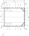
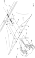
- Figure 1 diagrammatically illustrates a sealable package 100 according to an embodiment of the present invention.
- Figure 1 shows a front view of the package 100; in particular, the upper opening 5 of the package is positioned at an upper end of the drawing, while the lower edge 12 of the package 100 is positioned in the lower part of the drawing.
- the package 100 is sealable because, as will be apparent from the following description, after filling the package 100 through the upper opening 5 and having made, at such opening 5, a welding surface adapted to close the opening of the package, it will be impossible for the atmosphere outside the package to enter the package. Therefore, the environment inside the package 100 will be completely isolated with respect to the external environment of the package 100.
- the sealable package 100 made of flexible material comprises a front panel 1 and a back panel 2.
- the front panel 1 and the back panel 2 are connected by two side gussets: a right side gusset 3 and a left side gusset 4.
- Such side gussets 3, 4 are provided at opposite ends of the front panel 1 and of the back panel 2.
- the two side gussets 3, 4 comprise a sheet folded along a fold line L1 that is parallel to the axis Ax1 of the package. In this manner, an accordion structure is formed which allows increasing the distance between the front panel 1 and the back panel 2.
- the side gussets 3, 4 to comprise more than one fold line so as to significantly increase the distance between the two panels, and therefore significantly increase the volume of the package.
- the front panel 1, the back panel 2 and the two side gussets 3, 4 preferably are made of sheets made of flexible and sealable material. Such sheets preferably are sealable only on one of the two surfaces.
- the front panel 1 and the back panel 2 have the sealable surfaces facing the inside of the package 100.
- the side gussets 3 and 4 have sealable surfaces facing the inside of the package 100.
- the side gussets 3, 4 have sealable surfaces facing the front panel 1 and the back panel 2 so as to allow a seal between the side gussets 3, 4 and the front and back panels 1, 2, so as to allow a side closure of the package 100 to be ensured.
- the package has a reclosable opening 15 positioned at an area close to the opening 5 of the package 100.
- Such reclosable opening 15 preferably extends along a direction perpendicular to the axis Ax1 of the package 100.
- the reclosable opening is comprised between the side welding surfaces 22, 23.
- An example of reclosable opening is given by a zipper which allows reversibly opening and closing such package 100.
- the reclosable opening 15 therefore extends between the front panel 1 and the back panel 2: a first portion of the reclosable opening 15 is installed on the inner surface of the front panel 1 of the package 100, while a second portion of the reclosable opening 15 is installed on the inner surface of the back panel 2 of the package 100. In this manner, the first portion can be engaged with the second portion so as to ensure the closure of the package 100 also after the package 100 has been opened for the first time.
- An upper end portion of the side gussets 3 and 4 is folded along a fold line L2 which is inclined with respect to the axis Ax1 of the package 100.
- the portion folded along the fold line L2 therefore is an end portion of each side gusset 3, 4 which is in the vicinity of the opening 5 of the package 100.
- triangular portions 6 and 7 of the side gussets 3 and 4 results from folding the end portion of the side gussets 3,4, and therefore the possibility of having an upper portion of the package 100 free from gussets. This allows positioning the reclosable opening 15 in the area where there are only two layers of material (area having two thicknesses): the layer of the front panel 1 and the layer of the back panel 2.
- the triangular portions 6, 7 have the shape of a right-angled triangle having a hypotenuse that is inclined with respect to the axis Ax1 of the package and wherein the vertex of each triangular portion 6, 7, which is higher in the package 100, is positioned in a side area of the package at which the seal is made (which is further explained later), which allows joining the front panel 1 to the back one 2 with the side gussets 3, 4 comprised therebetween.
- Each of the two triangular portions 6, 7 therefore has a cathetus 8, 9 parallel to the outer edge 10, 11 of the package and another cathetus 13, 14 perpendicular to the outer edge 10, 11 of the package 100.
- each cathetus 8, 9 parallel to the outer edge 10, 11 of the package is positioned at a predetermined distance D1 from the outer edge of the package.
- this allows welding the front panel 1 to the gussets 3, 4 and then to the back panel 2, therefore “trapping" each triangular portion 6, 7. This therefore allows ensuring an effective sealing of the environment inside the package with respect to the external environment.
- side seals 22, 23 are made at the right 10 and left 11 side edges of the package, said seals allowing to close the package 100 along the right side and the left side.
- Such seals 22, 23 extend along the whole height h3 of the package. The width of such seals is greater than the above-described predetermined distance D1.
- the width of the welding surface 22 and 23 is greater than the first predetermined distance D1 so as to allow "trapping" the triangular portion between the front panel 1 and the back panel 2.
- predetermined distance D1 may preferably be greater than or equal to 1 mm, and in certain cases, also have larger sizes.
- the distance D1 preferably is greater than or equal to 4 mm. It is apparent that such distance strongly depends on the sizes of the package. For example, smaller packages have a smaller distance D1. Vice versa, larger packages have a larger distance D1.
- the distance D1 depends on the width of the side welding surfaces 22 and 23. To this end, the wider such surfaces, the greater the distance D1.
- a lower welding surface 27 adapted to close the bottom of the package 100 so as to prevent the material contained in the package to come out from the bottom, is positioned along the lower edge 12 of the package 100. Furthermore, there are two welding surfaces 25 and 26 that are inclined with respect both to the welding surface 22 and 23 and to the welding surface 27 to allow effectively emptying the package and at the same time strengthening the lower edges. The effective emptying is due to the fact that the welding surfaces 25 and 26 allow having a bottom of the package that is flat, and therefore easier to empty.
- This contrivance allows the material contained in the package 100 to effectively exit, which otherwise could be trapped at the lower corners of the package 100. Indeed, it is the object of the welding surfaces 25 and 26 to also reduce the possibility of part of the contents of the package to remain trapped at the lower edges.
- the side gussets 3 and 4 are positioned at a predetermined distance D2 with respect to the lower edge 12 of the package 100. This is due to the fact that in this manner, the lower portion of the gussets may be "trapped" between the front panel 1 and the back panel 2.
- distance D2 may vary according to the size of the package 100. As an indicative value, such distance preferably is greater than or equal to 1 mm. Moreover, most of the time such distance preferably is less than 5 mm.
- Packages like the ones shown in figure 1 may have a wide range of sizes. For example, they may have a size that varies from relatively small packages, configured so as to contain 0.1 kg of material, to much larger packages, that allow containing up to 20 kg of material.
- the right side gusset 3 and the left side gusset 4 extend along the side edge 10, 11, of the package up to a height h1 from the lower edge 12 of the package 100. Therefore as shown in the drawing, the height h3 of the package 100 is equal to the sum of the distance h2 of the upper end portion of the gussets 3, 4 up to the upper edge 5, with the distance h1.
- Such gussets 3, 4 are positioned at the predetermined distance D2 with respect to the lower edge 12 of the package 100 which therefore is represented by the lower edge of the front panel 1 and of the back panel 2.
- the upper end portion of the right 3 and left 4 side gusset is positioned at a distance h2 of the opening 5 of the package 100. This allows having an inner portion of the package 100 free from gussets and therefore also an effective exit of the material contained in the package 100.
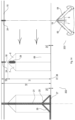
- Figure 2 shows a machine 200 according to an embodiment of the present invention.
- the machine 200 shown in the drawing comprises four stations.
- a first station 201 is configured so as to prepare a strip of material which is then coupled in station 202 with the tubular element coming from the station 203.
- the station 203 is then configured so as to form the side gussets 2 and 3 of the package 100, which are shown in figure 1 .
- Downstream of the coupling station 202 there is positioned a packaging station 204 wherein the package produced in the coupling station 202 is opened, filled with the contents of the package and finally closed at the opening 5 of the package 100 so as to seal the environment inside the package with respect to the external environment.
- the package 100 described in the present invention is a sealable package in the sense that the contents of the package are isolated with respect to the external environment when the upper opening of the package 5 is closed, therefore after the package 100 has been filled. Therefore, the external air cannot enter towards the interior of the package 100 and vice versa, the internal air cannot exit towards the exterior of the package.
- the preparing station 201 which is a vertical station in the particular example depicted in the drawing, the coupling station 202 and the tubular element forming station 203, are described in detail.
- the method for making the package 100 will be apparent from the description of the various stations of the machine 200 and of how such stations contribute to making the package 100.
- the preparing station 201 comprises a reel 72 on which a sheet 70 made of flexible material is wound, which as mentioned above, is sealable on one of the two sides.
- the sheet 70 is unrolled from the reel 72 and conducted towards a forming device 73 which allows bending the sheet in half so as to form a folded sheet having a width equal to half the width that the sheet 70 had when it was positioned on the reel 72.
- the sheet 70 is unrolled from the reel 72 and conveyed along the conveying direction indicated by the arrow in figure 3 towards the forming device 73, where it is folded.
- a blade 71 is positioned immediately downstream of the forming device 73, which blade allows cutting the sheet 70, therefore dividing it into two equal parts along the fold line that was provided by the forming device 73.
- the sheets 19, 20 have the sealable surfaces facing each other while the outer surfaces are not sealable, thus allowing the two sheets to be sealed to each other.
- a reel 74 is placed downstream of the blade 71, on which reel a zipper length 15 is wound, which may be used as reclosable opening of the package 100.
- the zipper length 15 is unrolled from the reel 74 and coupled to both sheets 19, 20 produced downstream of the blade 71.
- the zipper length 15 is coupled to the front sheet 19 and the back sheet 20 by means of welding bars 42 which allow welding the reclosable opening 15 to what will be the panels 1, 2 of the package 100.
- the reclosable zipper 15 is provided from reel 74 and is coupled both with the front sheet and with the back sheet by means of the seal provided by the welding bars 42.
- the reclosable opening 15 is opened, that is after a first portion of the reclosable opening 15 is uncoupled from a second portion of the reclosable opening 15, the first portion of the reclosable opening 15 is constrained to the front sheet 19 and the second portion to the back sheet 20.
- the reclosable zipper 15, which comprises such first and second portion, is conveyed into the portion comprised between the sheet 19 and the sheet 20 and is sealed thereto.
- Such portions preferably are then uncoupled from each other, after the welding has been performed by means of the welding bars 42.
- a contrast element (not shown in the drawing) with the purpose of separating the first portion of the reclosable opening 15 from the second one preferably is positioned downstream of the welding bars 42.
- Welding grippers 43 are placed downstream of the welding bars 42, which as mentioned, are configured so as to longitudinally seal the zipper 15, the welding grippers allowing to make welding surfaces 24 along a direction perpendicular to the conveying direction of the sheets 19 and 20. In the case wherein there is the above-described contrast element, it is between the welding bars 42 and the welding grippers 43.
- welding surfaces 24 which are introduced in greater detail with reference to the following drawings, allow securing the front sheet 19 to the back sheet 20 with the reclosable opening 15 comprised between such sheets 19, 20. Moreover, it is possible to flatten the zipper 15 at such welding surfaces 24 in order to reduce the thickness thereof. This then allows facilitating the side seals of the package, which are described later.
- Each welding surface 24 produced by the welding grippers 43 is positioned close to the edge of the sheets 19 and 20.
- the term "close to” here means that there may also be a given distance between the edge of the sheets 19 and 20 and such welding surface 24, which is due for example, to margins of error required when positioning the welding grippers 43. In any case, it is preferable for such welding surface to be positioned next to the edge of the sheets 19, 20.
- the closing surface which then is the upper edge of the package 100 at which the opening 5 of the package 100 is positioned, extends along a direction parallel to the edge of the sheets 19, 20, i.e. longitudinal to the conveying direction of the sheets 19, 20. It therefore is apparent that given that the distance (see distance M1 in figure 13 ) between two consecutive midpoints of welding surfaces 24 is measured along the conveying direction of the sheets 19, 20, it is equal to the width of the package 100 that is then formed.
- the length h4 (shown in figure 10 ) of such welding surfaces 24 preferably is comprised between 35 mm and 50 mm. According to a particular embodiment, such extension preferably is equal to 40 mm. In any case, the above-mentioned extensions strongly depend on the height of the final package 100 and therefore on the width of the sheets 19, 20 which as described later, coincides with the longitudinal extension h3 of the package.
- the sheets 19 and 20 are conveyed downstream of the welding grippers 43 in downstream direction by means of the aid of movement elements (not shown in the drawing), which for example, are simple rollers.
- the procedure used by the preparing station 201 is shown in greater detail with reference to figure 4 .
- Figure 4 clearly shows how at a given distance downstream of the portion where the welding surfaces 24 are made, the front sheet and the back sheet 19 and 20 are opened with respect to each other along an edge 37, 38 that is opposite to the edge along which the above-described welding surfaces 24 are made.
- the edge 37 of the back sheet 20 and the edge 38 of the front sheet 19 therefore are positioned at the one which forms the lower edge 12 of the package 100.
- the coupling station 202 is positioned downstream of such first preparing station 201, the coupling station being configured so as to couple the sheet 19 and the sheet 20 coming from the first station 201 with the tubular element 61 coming from the tubular element forming station 203, which is described later.
- the conveying direction of the tubular element 61 is perpendicular to the conveying direction of the front sheet 19 and of the back sheet 20 described above.
- a sheet 60 is rolled along a reel 62 configured to rotate about an axis 63.
- the sheet 60 is unrolled and the tubular element 61 is formed with the aid of a commonly known forming device (not shown in the drawing).
- Tubular element means a sheet having a flattened tube structure that extends along a direction.
- the tubular element is formed from a sheet through two mutually parallel fold lines L1.
- the two fold lines L1 allow moving the outer edges of the sheet 60 closet to each other so that the right edge of the sheet is positioned at the left edge of the sheet. The point wherein the right edge of the sheet meets with the left edge of the sheet coincides with the midpoint of the tubular element.
- the fold lines L1 indeed are arranged at the same distance with respect to the outer edges of the sheet 60.
- FIG. 5B An example of the structure having tubular element 61 is clearly shown in the section view A-A in figure 5B .
- Such drawing shows the fact that the tubular structure 61 has a lower edge that is continuous, while an upper edge has a slight discontinuity.
- the reason for the discontinuity lies in the fact that as described above, the upper edge of the tubular element 61 comprises the right edge of the sheet 60 and the left edge of the sheet 60 placed at each other. Therefore, there is a central portion of the upper edge of the tubular element 61 that represents a transition portion between the left edge and the right edge of the sheet 60.
- the forming device that folds the sheet 60 along the fold lines L1 allows positioning the outer edges of the sheet 60 at each other so as to substantially make such discontinuity zero. It is worth noting that for illustrative purposes, such distance between the left and right edges is rather accentuated in figure 5B so as to allow the reader to understand that it is a tubular element and that the portion where there is such discontinuity is the portion where the right edge and the left edge of the sheet 60 meet. In reality, it is apparent that the area of discontinuity provided by the forming device is much less apparent.
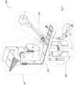
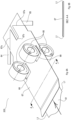
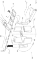
- FIG. 6A and 6B show the elements that allow the tubular element 61 to be folded and conveyed.
- figure 6A shows that the conveying of the tubular element 61 along a direction perpendicular to the conveying direction of the sheets 19 and 20 shown in figure 3 , is ensured by counter-rotating rollers 66 placed at two different levels.
- the tubular element 61 is conveyed below a plate 67 on which there are provided two openings 68 which allow the counter-rotating rollers 66 to directly contact the tubular element and to convey it along a conveying direction by means of the rotation thereof.
- the number of openings 68 is equal to two, the number of rollers is therefore equal to four.
- the sheet 60 is a sheet made of flexible material having a welding surface and a non-welding surface.
- the welding surface is the one external to the tubular element 61 that therefore forms the outer surface of the tubular element, while the non-welding surface is the inner one with respect to the tubular element 61.
- each pair of rollers 66 positioned respectively above and below the plate 67 comprises two rollers 66, wherein one roller is configured so as to rotate in opposite direction with respect to the roller positioned above/below it.
- the folding means 64 and 65 are positioned at the bottom with respect to the tubular element 61 so that the tubular element
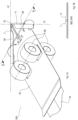
- folding means 64 and 65 are shown more clearly with reference to figure 7A .
- such means have a substantially rectangular shape.
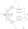
- such folding means 64 and 65 have an inner edge having a form that deviates from the rectilinear one in the particular state shown in figure 7A (that is, after they have performed the rotation about the axis thereof, thus forming the arrow structure).
- the central "pointed" end portion allows optimizing the folding process.
- the cavity positioned at the central end portion of the folding means 64 and 65 allows securing the fold by means of welding, as will be more apparent when the welding means 44 are described.
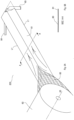
- the fold of the end portion of the tubular element 61 is ensured by the joint operation carried out by the folding means 64 and 65 and by the inclined edges 67a of the end edge of the plate 67 that have a similar shape to the one of the folding means 64 and 65.
- the end edge of the plate 67 has two portions 67a that are inclined with respect to the axis of the tubular element 61 and are symmetrical with respect thereto. Such inclined portions 67a substantially are arranged parallel to the folding means 64 and 65.
- the end edge of the plate 67 has a substantially rectangular opening 67b positioned at the axis of the tubular element 61.
- an end portion of the tubular element having a substantially trapezoidal shape is formed by means of the fold of the end portion of the tubular element 61.
- Figure 7B shows a section view along the cutting line B-B in figure 7A .
- the section view there are two triangular portions 6 and 7 that, after the fold is made, are not perfectly resting on the tubular element 61 itself due to the fact that the end portion of the plate 67 is comprised between the tubular element 61 and the triangular portions 6 and 7.
- Figure 8 clearly shows a top view of the state of the end portion of the tubular element 61 after the fold is made by means rotating the folding means 64 and 65 about the axis thereof, with the co-participation of the oblique end portion 67a of the plate 67 that allowed making the fold along the fold lines L2 that coincide with the inclination of the oblique end portion 67a.
- Figure 9 shows a successive state with respect to the one shown in figure 8 .
- a seal between the triangular portions 6 and 7 and the central portion of the tubular element 61 is made in this state due to the fact that the oblique portions 67a are placed at a given distance due to the rectangular opening 67b, as mentioned above.
- the triangular portions 6, 7 it is possible to secure the triangular portions 6, 7 to the tubular element 61 itself so that the fold line L2 that was provided in the preceding step is kept following a successive movement of the tubular element 61.
- the welding means 44 allow welding the triangular portions 6 and 7 to the tubular element 61 by means of two seal stretches 28 that extend mutually parallel along the sides of the triangular portions 6, 7.
- each of the two seal stretches 28 seals respectively one of the triangular portions 6, 7 to the tubular element 61.
- the number of seal stretches 28 may vary, as the shape of such stretches may vary.
- the triangular portions 6, 7 could also be "tacked" to the tubular element 61 by means of one or more circular seal spots positioned at the axis of the tubular element 61, wherein such seal spots preferably would allow simultaneously welding both triangular portions 6, 7 to the tubular element.
- shape of the tacking can also be other than circular, such as for example ellipsoid-shaped.
- tack spots alternatively can also be made in side portions with respect to the axis of the tubular element 61.
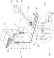
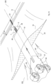
- the tubular element 61 is conducted into a portion comprised between the front sheet 19 and the back sheet 20 along a direction perpendicular to the conveying direction of the sheets 19 and 20.
- the tubular element 61 is conveyed into the inner area between the sheet 19 and the sheet 20, at the welding surface 24 that was made before, so that the axis of the tubular element 61 coincides with the symmetry axis (perpendicular to the edges 19, 20) of the welding surface 24. This contrivance is important because in this manner, it is possible to make packages having a central symmetry axis.
- the conveying of the tubular element 61 is ensured by the rotation means 66 that allow the insertion thereof into the portion comprised between the front sheet 19 and the back sheet 20.
- the tubular element 61 is inserted until the upper base 16 reaches a distance h2 with respect to the edge of the sheet 19, 20 that is opposite to the one 37, 38 at which the tubular element 61 was inserted.
- the distance h2 preferably is in the range of tens of a millimetre, for example greater than or equal to 40 mm, more preferably greater than or equal to 50 mm. Such distance strongly depends on the sizes of the package 100. As described above with respect to the package 100, this distance h2 allows having the great advantage that an upper portion of the package 100 is free from gussets at which a reclosable opening 15 can be positioned.
- the tubular element 61 After the tubular element 61 has reached such distance h2 from the opposite edge with respect to which it was inserted, the tubular element 61 is cut through cutting means 33 along the cutting line L3 placed at a distance D2 with respect to the lower edge of the package so as to separate a tubular element portion 69.
- This distance D2 was already described above with reference to the package in figure 1 and as mentioned above, serves to allow effectively closing the side gussets 3, 4 within a lower welding surface 27. Therefore, the cutting means 33 are positioned between the front sheet 19 and the back sheet 20 to allow such cutting.
- the tubular element portion 69 is conveyed into the area comprised between the sheets 19 and 20 until the tubular element portion 69 reaches the distance h2 from the above-described edge and therefore, accordingly reaches the distance D2 from the edge at which such tubular element portion 69 is inserted.
- a further welding surface 29 is made that allows welding the three components together.
- Such welding surface 29 can have various shapes.
- the seal is obtained by means of a welding surface 29 that circumscribes both the seal stretches 28 shown in figure 10 .
- welding could alternatively be obtained by means of one or more seal spots having for example, circular shape.
- welding surfaces may be obtained.
- larger welding surfaces can also be applied, that interact with the welding surface 24 made beforehand.
- the tubular element 61 to which the tubular element portion 69 cut beforehand was secured is brought back, following the direction shown by the arrow in figure 12 .
- Such translation is ensured by the rotation of the rotation means 66 that rotate in the opposite direction with respect to what is described for example, in figure 10 . It is apparent that such rotation of the rotation means 66 to cause the tubular element 61 to retract towards the folding means 64, 65 becomes necessary because the tubular element 61 was cut at the area comprised between the two sheets 19, 20.
- Such rotation described here is not necessary if the cutting means 33 are positioned at a given distance from the sheets 19, 20, for example upstream of the folding means 64 and 65.
- the folding means 64 and 65 make a new fold on the end portion of the tubular element 61 and in the same manner, the front and back sheets 19, 20 to which the tubular element portion 69 was sealed are caused to slide along the conveying line shown in the drawing, which allows reaching the successive stations that are described with reference to figure 14 .
- FIG 14 indeed shows that the welding 21 that allows making the actual package 100 occurs in a successive section of the coupling station 202. Indeed, welding surfaces 21 are obtained perpendicular to the conveying direction, which form the side seals 22, 23 of the package 100, as described with reference to figure 1 .
- the welding surface 21 overlaps the welding surface 24 obtained by the welding grippers 43 and the welding surface 29 obtained to secure the tubular element portion 69 to the sheets 19, 20 so as to prevent the tubular element portion 69 from moving during a conveying towards the area of the machine wherein the welding surface 21 is obtained.
- the central axis of the welding surface 21 coincides with the central axis of the sealed surface 24.
- the seal 21 has a width equal to twice the above-described distance D1, plus a predetermined quantity that will allow forming the triangular portions 6, 7 of the tubular element at the edges of the package 100.
- seals 27 for the lower closure of the package and the oblique seals 25 and 26 that as described above, allow preventing the content of the package to possibly remain in the corners of the package itself and to provide the package 100 with a flat bottom.
- the package 100 is ready to be separated from the sheet itself so as to form a true package. Therefore, it is possible to separate the packages 100 from one another by making a cut along the cutting line L4 by means of the cutting means 34.
- the cutting line L4 is perpendicular to the conveying direction of the packages and divides the seal 21 into two perfectly equal parts.
- the reclosable opening 15 preferably is in an open state, that is in a state wherein the first portion of the reclosable opening 15 positioned on the inner side of the front panel 1 is uncoupled from the second portion of the reclosable opening 15 positioned on the inner side of the back panel 2. In this manner, it is possible to provide packages 100 that are ready to be filled without the need to uncouple the first portion from the second portion of the reclosable opening 15, which could result in an increased waste of time.
- a carousel may be placed at this point that is configured so as to receive the packages 100 provided by the coupling station 202, to open them so as to insert the contents of the package through the opening 5 of the package 100.
- the package 100 is opened in a successive step, forming an open package 101, the open package 101 is then filled by means of a funnel, thus forming a filled package 102.
- the filled package 102 is then closed, forming a closed package 103 that is then sealed, thus forming the package 105 shown in the drawing that can then be provided to the outside.
- the preparing station 201 can perform the operations described above while the tubular element forming station 203 makes the tubular element 61.
- continuous means a process that allows making packages one after another, thus with a temporal distance between making one package and the next.
- continuous here therefore means that while one station performs a given process on a package, another station performs another process on another package, that is that each station preferably can work continuously.
- the temporal distance between making two successive packages is due to the fact that the different steps are to be performed along the production line of the packages: from the various seals to the various folds.
- the present invention is also valid for packages that do not have a reclosable opening.
- the machine comprises four stations, it is possible to make a machine that contains only some of such stations.
- the filling station 204 may be omitted in many cases wherein the production of packages and not the filling thereof, is required.
- the preparing station 201 is a vertical station, it also is alternatively possible for such station to be a horizontal preparing station. Moreover, both with regards to the preparing station 201 and to the tubular element forming station 203, when reel is discussed, it means more generally any system capable of continuously providing a strip of sheet or a reclosable opening.
Landscapes
- Engineering & Computer Science (AREA)
- Mechanical Engineering (AREA)
- Bag Frames (AREA)
- Making Paper Articles (AREA)
- Packages (AREA)
- Auxiliary Devices For And Details Of Packaging Control (AREA)
Claims (13)
- Verfahren zur Herstellung von luftdicht verschließbaren Verpackungen (100) aus flexiblem Material, die ausgebildet sind zum
Abdichten einer Umgebung im Inneren der Verpackung gegenüber einer äußeren Umgebung, wobei die Verpackungen (100) eine Vorderwand (1), eine Rückwand (2) und zwei Seitenfalten (3, 4) aufweisen, die an gegenüberliegenden Enden der Vorderwand (1) und der Rückwand (2) vorgesehen sind, um die Vorderwand (1) mit der Rückwand (2) zu verbinden, mit den folgenden Schritten:a) Falten eines Bogens (60) aus flexiblem Material entlang zweier erster Faltlinien (L1), die zueinander parallel sind, um ein rohrförmiges Element (61) zu bilden, das die beiden Seitenfalten (3, 4) bilden wird;b) Falten eines Endabschnitts des rohrförmigen Elements (61) entlang zweier zweiter Faltlinien (L2), die in Bezug auf die Richtung der ersten Faltlinien (L1) schräg verlaufen, um einen Endabschnitt des rohrförmigen Elements (61) zu bilden, der zwei dreieckige Abschnitte (6, 7) mit zwei zueinander parallelen Seiten (8, 9) aufweist, wobei jede der zueinander parallelen Seiten (8, 9) in einem ersten vorbestimmten Abstand (D1) von einer Außenkante der Verpackung (100) positioniert ist und in dem rohrförmigen Element (61) die zueinander parallelen Seiten (8, 9) einen Abstand zueinander haben, der gleich dem Doppelten des ersten vorbestimmten Abstands (D1) ist;c) Transportieren des rohrförmigen Elements (61) mit den dreieckigen Abschnitten (6, 7), um es zwischen einem vorderen Bogen (19), der die Vorderwand (1) oder die Rückwand (2) der Verpackung (100) bildet, und einem hinteren Bogen (20), der die Rückwand (2) oder die Vorderwand (1) der Verpackung (100) bildet, einzufügen;d) Schneiden des rohrförmigen Elements (61) entlang einer ersten Schnittlinie (L3), die senkrecht zur Achse des rohrförmigen Elements (61) verläuft, um einen Abschnitt (69) des rohrförmigen Elements (61) abzutrennen. - Verfahren zur Herstellung von verschließbaren Verpackungen (100) nach Anspruch 1, wobei der erste vorbestimmte Abstand (D1) größer oder gleich 1 mm, vorzugsweise größer oder gleich 4 mm ist.
- Verfahren zur Herstellung von verschließbaren Verpackungen (100) nach Anspruch 1 oder 2, wobei das Verfahren ferner den folgenden Schritt umfasst:
e) Befestigen der dreieckigen Abschnitte (6, 7) an dem rohrförmigen Element (61), vorzugsweise durch Anschweißen der dreieckigen Abschnitte (6, 7) an dem rohrförmigen Element (61). - Verfahren zum Herstellen von verschließbaren Verpackungen (100) nach einem der Ansprüche 1 bis 3, wobei während des Schritts d) die erste Schnittlinie (L3), entlang der das röhrenförmige Element (61) geschnitten wird, in einem zweiten vorbestimmten Abstand (D2) in Bezug auf eine Kante (37, 38) der Bögen (19, 20) positioniert wird, an der das röhrenförmige Element (61) zwischen die Bögen (19, 20) eingefügt wird; wobei der zweite vorbestimmte Abstand (D2) vorzugsweise zwischen 1 und 5 mm liegt, besonders bevorzugt gleich 3 mm ist.
- Verfahren zum Herstellen von verschließbaren Verpackungen (100) nach einem der Ansprüche 1 bis 4, wobei während des Schritts c) das rohrförmige Element (61) bis zum Erreichen eines dritten vorbestimmten Abstands (h2) in Bezug auf eine Kante der Bögen (19, 20) gegenüber einer Kante (37, 38), an der das rohrförmige Element (61) zwischen die Bögen (19, 20) eingefügt wird, transportiert wird; wobei der dritte vorbestimmte Abstand (h2) vorzugsweise größer als oder gleich 40 mm, mehr bevorzugt größer als oder gleich 50 mm ist.
- Verfahren zum Herstellen von verschließbaren Verpackungen (100) nach einem der Ansprüche 1 bis 5, wobei das Verfahren ferner den folgenden Schritt umfasst:
f) Befestigen des Abschnitts (69) des rohrförmigen Elements an dem vorderen Bogen (19) und an dem hinteren Bogen (20) durch Schweißen entlang einer Schweißfläche (21), die parallel zur Achse des Abschnitts (69) des rohrförmigen Elements verläuft und an der Achse des Abschnitts (69) des rohrförmigen Elements angeordnet ist; wobei eine Breite der Schweißfläche (21) größer ist als das Doppelte des ersten vorbestimmten Abstands (D1), wobei der Abschnitt (69) des rohrförmigen Elements vorzugsweise an dem vorderen Bogen (19) und an dem hinteren Bogen (20) befestigt ist, so dass die untere Kante des Abschnitts (69) des rohrförmigen Elements in einem zweiten vorbestimmten Abstand (D2) in Bezug auf eine Kante (37, 38) der Bögen (19, 20) positioniert ist, bei dem das rohrförmige Element (61) zwischen die Bögen (19, 20) eingefügt wird, so dass es von der Kante (37, 38) der Bögen (19, 20) beabstandet ist. - Verfahren zum Herstellen von verschließbaren Verpackungen (100) nach Anspruch 6, wobei das Verfahren ferner den folgenden Schritt umfasst:
g) Schneiden der Schweißfläche (21) entlang einer zweiten Schnittlinie (L4), die parallel zur Achse des röhrenförmigen Elements (61) verläuft und an der Achse des röhrenförmigen Elements (61) angeordnet ist, wobei sich die zweite Schnittlinie (L4) über eine Länge erstreckt, die gleich der Höhe (h3) der Verpackung (100) ist, um eine Verpackung von der nächsten zu trennen, wobei die zweite Schnittlinie (L4) in gleichem Abstand von den zueinander parallelen Seiten (8, 9) der dreieckigen Abschnitte (6, 7) angeordnet ist. - Vorrichtung (200) zur Herstellung von luftdicht verschließbaren Verpackungen (100) aus flexiblem Material, die ausgebildet sind, eine Umgebung innerhalb der Verpackung gegenüber einer äußeren Umgebung abzudichten, wobei die Verpackungen (100) eine Vorderwand (1) und eine Rückwand (2) und zwei Seitenfalten (3, 4) aufweisen, die an gegenüberliegenden Enden der Vorderwand (1) und der Rückwand (2) vorgesehen sind, um die Vorderwand (1) mit der Rückwand (2) zu verbinden, wobei die Vorrichtung eine Station (203) zum Formen eines rohrförmigen Elements aufweist, die ausgebildet ist, ein rohrförmiges Element (61), das die beiden Seitenfalten (3, 4) bildet, aus einem Bogen (60) zu formen, wobei die Station (203) zum Formen eines rohrförmigen Elements eine Falteinrichtung (64, 65) aufweist, die ausgebildet ist, einen Endabschnitt des rohrförmigen Elements (61) entlang von Faltlinien (L2) falten, die in Bezug auf die Achse des rohrförmigen Elements (61) schräg verlaufen, so dass ein Abschnitt des rohrförmigen Elements (61) einen Endabschnitt des rohrförmigen Elements (61) mit zwei dreieckigen Abschnitten (6, 7) mit zwei zueinander parallelen Seiten (8, 9) aufweist, wobei jede der zueinander parallelen Seiten (8, 9) in einem ersten vorbestimmten Abstand (D1) von einer Außenkante der Verpackung (100) positioniert ist und die zueinander parallelen Seiten (8, 9) einen Abstand zueinander aufweisen, der gleich dem Doppelten des ersten vorbestimmten Abstands (D1) ist, so dass sie voneinander beabstandet sind;
wobei die Vorrichtung (200) ferner eine Kopplungsstation (202) aufweist, die in einem vorbestimmten Abstand in Bezug auf die Station (203) zum Formen des rohrförmigen Elements angeordnet ist, wobei die Kopplungsstation (202) ausgebildet ist, das rohrförmige Element (61), das aus der Station (203) zum Formen des rohrförmigen Elements eintrifft, aufzunehmen und es zwischen einem vorderen Bogen (19), der die Vorderwand (1) oder die Rückwand (2) der Verpackung (100) bilden wird, und einem hinteren Bogen (20), der die Rückwand (1) oder die Vorderwand (2) der Verpackung (100) bilden wird, einfügt und wobei eine Schneideeinrichtung (33), die ausgebildet sind, einen Abschnitt (69) des rohrförmigen Elements (61) von dem rohrförmigen Element (61) entlang einer ersten Schnittlinie (L3), die eine Richtung senkrecht zur Achse des rohrförmigen Elements (61) hat, abzutrennen, zwischen der Station (203) zum Bilden des rohrförmigen Elements und der Kopplungsstation (202) angeordnet ist. - Vorrichtung (200) nach Anspruch 8, wobei die Station (203) zum Formen eines rohrförmigen Elements ferner eine Befestigungseinrichtung (44) aufweist, die ausgebildet ist, die dreieckigen Abschnitte (6, 7) an dem rohrförmigen Element (61), vorzugsweise durch Schweißen, zu befestigen.
- Vorrichtung (200) nach einem der Ansprüche 8 oder 9, wobei die Station (203) zum Formen eines rohrförmigen Elements ferner eine Bewegungseinrichtung aufweist, die vorzugsweise rotierende Elemente (66) aufweist, die ausgebildet sind, die Bewegung des rohrförmigen Elements (61) entlang einer Transportrichtung parallel zur Achse des rohrförmigen Elements (61), vorzugsweise durch die Drehung der rotierenden Elemente (66), zu ermöglichen.
- Vorrichtung (200) nach einem der Ansprüche 8 bis 10, wobei die erste Schnittlinie (L3) der Schneideinrichtung (33) in einem zweiten vorbestimmten Abstand (D2) in Bezug auf eine Kante (37, 38) der Bögen (19, 20) positioniert ist, an der das rohrförmige Element (61) eingeführt wird, um zu ermöglichen, dass der Abschnitt (69) des rohrförmigen Elements vollständig in einer unteren Verschlussdichtung (27) geschlossen wird, die ausgebildet ist, die Verpackung (100) an der Unterseite zwischen dem vorderen (19) und dem hinteren Bogen (20) zu verschließen, wobei der zweite vorbestimmte Abstand (D2) vorzugsweise zwischen 1 mm und 5 mm liegt, besonders bevorzugt gleich 3 mm ist.
- Vorrichtung (200) nach einem der Ansprüche 8 bis 11, wobei die Vorrichtung (200) ferner eine Vorbereitungsstation (201) aufweist, die ausgebildet ist, die Bögen (19, 20) für die Kopplungsstation (202) bereitzustellen; wobei die Vorbereitungsstation (201) aufweist:eine Schneideeinrichtung (71), die ausgebildet ist, einen von einer Rolle (72) kommenden Bogen (70) derart zu schneiden, dass der vordere Bogen (19) und der hintere Bogen (20) gleiche Größen haben;eine erste Schweißeinrichtung (42) mit einer Richtung, die mit der Transportrichtung der Bögen (19, 20) zusammenfällt, die ausgebildet ist, ein wiederverschließbares Element (15), das von der Rolle (74) kommt, an dem vorderen Bogen (19) und dem hinteren Bogen (20) zu befestigen, undeine zweite Schweißeinrichtung (43) mit einer Richtung senkrecht zur Transportrichtung der Bögen (19, 20), die ausgebildet ist, den vorderen Bogen (19) an dem hinteren Bogen (20) zu befestigen, wobei sich das wiederverschließbare Element (15) zwischen den Bögen (19, 20) befindet.
- Vorrichtung (200) nach einem der Ansprüche 8 bis 12, wobei die Kopplungsstation (202) ferner eine Schweißeinrichtung aufweist, die ausgebildet ist, den Abschnitt (69) des rohrförmigen Elements an dem vorderen Bogen (19) und an dem hinteren Bogen (20) zu befestigen, wobei die Schweißeinrichtung vorzugsweise ausgebildet ist, Dichtungen an einer Schweißfläche (22, 23) der Verpackung (100) herzustellen, wobei die Schweißfläche (22, 23) parallel zur Achse der Verpackung (100) liegt und eine Breite größer ist als das Doppelte des ersten vorbestimmten Abstands (D1).
Applications Claiming Priority (2)
| Application Number | Priority Date | Filing Date | Title |
|---|---|---|---|
| IT102018000005107A IT201800005107A1 (it) | 2018-05-07 | 2018-05-07 | Produzione di confezioni sigillabili con soffietti laterali |
| PCT/IB2019/053738 WO2019215615A1 (en) | 2018-05-07 | 2019-05-07 | Production of airtight packages with side gussets |
Publications (3)
| Publication Number | Publication Date |
|---|---|
| EP3790809A1 EP3790809A1 (de) | 2021-03-17 |
| EP3790809C0 EP3790809C0 (de) | 2023-11-08 |
| EP3790809B1 true EP3790809B1 (de) | 2023-11-08 |
Family
ID=63014900
Family Applications (1)
| Application Number | Title | Priority Date | Filing Date |
|---|---|---|---|
| EP19726514.3A Active EP3790809B1 (de) | 2018-05-07 | 2019-05-07 | Verfahren und maschine zur herstellung von luftdichten verpackungen mit seitenfalten |
Country Status (7)
| Country | Link |
|---|---|
| US (1) | US11780646B2 (de) |
| EP (1) | EP3790809B1 (de) |
| JP (1) | JP7257420B2 (de) |
| CA (1) | CA3098806C (de) |
| ES (1) | ES2970811T3 (de) |
| IT (1) | IT201800005107A1 (de) |
| WO (1) | WO2019215615A1 (de) |
Families Citing this family (3)
| Publication number | Priority date | Publication date | Assignee | Title |
|---|---|---|---|---|
| IT202300008496A1 (it) * | 2023-05-02 | 2024-11-02 | Ilapak Italia S P A | Macchina e metodo per la formatura di buste di materiale flessibile. |
| IT202400012622A1 (it) | 2024-06-03 | 2025-12-03 | Ica Spa | Gruppo per l'apertura di confezioni |
| WO2026027999A1 (en) | 2024-08-02 | 2026-02-05 | Ica S.P.A. | Filling of packages |
Family Cites Families (14)
| Publication number | Priority date | Publication date | Assignee | Title |
|---|---|---|---|---|
| DE1629218B2 (de) | 1966-06-01 | 1973-04-26 | Windmoller & Holscher, 4540 Len gench | Verfahren und vorrichtung zum herstellen von kunststoffbeuteln mit angeschweissten druck- oder gleitverschlussbaendern |
| JP3872564B2 (ja) * | 1996-06-14 | 2007-01-24 | 株式会社メイワパックス | サイドガゼット袋の製造法 |
| JPH1128771A (ja) | 1997-07-09 | 1999-02-02 | Totani Corp | 製袋方法および製袋機 |
| US20010053253A1 (en) * | 2000-03-24 | 2001-12-20 | Reynolds Consumer Products, Inc. | Reclosable package having zipper closure, slider device and dual tamper-evident structures; and methods |
| JP2003300263A (ja) | 2002-04-10 | 2003-10-21 | Koji Onuma | ガセット付き扁平袋の製造方法 |
| JP3733085B2 (ja) | 2002-06-03 | 2006-01-11 | トタニ技研工業株式会社 | プラスチック袋およびその製袋機 |
| CN1256260C (zh) * | 2002-07-24 | 2006-05-17 | 户谷技研工业株式会社 | 塑料袋和塑料袋制造装置 |
| JP3826124B2 (ja) * | 2003-10-06 | 2006-09-27 | トタニ技研工業株式会社 | プラスチック袋 |
| JP4806565B2 (ja) * | 2005-12-19 | 2011-11-02 | トタニ技研工業株式会社 | プラスチック袋 |
| JP5171873B2 (ja) * | 2010-04-19 | 2013-03-27 | 株式会社細川洋行 | ガゼット袋を製造する方法 |
| TR201904565T4 (tr) | 2013-09-18 | 2019-04-22 | Mamata Machinery Pvt Ltd | Plastik torba imalatına yönelik makine ve yöntem. |
| US9662852B2 (en) * | 2014-11-11 | 2017-05-30 | Totani Corporation | Plastic bag making apparatus |
| JP5913699B1 (ja) * | 2015-07-24 | 2016-04-27 | トタニ技研工業株式会社 | プラスチック袋およびその製袋機 |
| ES2600166B1 (es) * | 2015-07-24 | 2017-11-17 | Pfm Ibérica Packaging Machinery, S.A. | Un procedimiento para la fabricación de contenedores flexibles que comprenden una base inferior de configuración esencialmente rectangular |
-
2018
- 2018-05-07 IT IT102018000005107A patent/IT201800005107A1/it unknown
-
2019
- 2019-05-07 US US17/053,094 patent/US11780646B2/en active Active
- 2019-05-07 JP JP2020562205A patent/JP7257420B2/ja active Active
- 2019-05-07 CA CA3098806A patent/CA3098806C/en active Active
- 2019-05-07 EP EP19726514.3A patent/EP3790809B1/de active Active
- 2019-05-07 ES ES19726514T patent/ES2970811T3/es active Active
- 2019-05-07 WO PCT/IB2019/053738 patent/WO2019215615A1/en not_active Ceased
Also Published As
| Publication number | Publication date |
|---|---|
| EP3790809C0 (de) | 2023-11-08 |
| IT201800005107A1 (it) | 2019-11-07 |
| WO2019215615A1 (en) | 2019-11-14 |
| US20210070503A1 (en) | 2021-03-11 |
| CA3098806A1 (en) | 2019-11-14 |
| ES2970811T3 (es) | 2024-05-30 |
| EP3790809A1 (de) | 2021-03-17 |
| CA3098806C (en) | 2023-03-14 |
| JP2021522091A (ja) | 2021-08-30 |
| US11780646B2 (en) | 2023-10-10 |
| JP7257420B2 (ja) | 2023-04-13 |
Similar Documents
| Publication | Publication Date | Title |
|---|---|---|
| EP3790733B1 (de) | Verfahren und maschine zum herstellen von flexiblen verpackungen mit seitenfalten | |
| US6131369A (en) | Method of applying slider to package having reclosable zipper | |
| EP1712488B1 (de) | Flexible Verpackung und Verfahren zu ihrer Herstellung | |
| US6530870B2 (en) | Methods of manufacturing reclosable packages; and packages made thereby | |
| US7351188B2 (en) | Hooded reclosable packages and related methods of manufacture | |
| US7322920B2 (en) | Easy-open shrouded slider-zipper assembly for reclosable bag | |
| US20050034425A1 (en) | Method for sealing zipper assembly to bag making film at three or more points | |
| CA3098806C (en) | Production of airtight packages with side gussets | |
| KR20120100906A (ko) | 재밀폐 가능한 플라스틱 헤더를 구비한 카톤 | |
| EP3395709B1 (de) | Verfahren und einrichtung zur herstellung von verpackungen aus biegsamen material mit seitenfalten | |
| EP2064124B1 (de) | Wiederverschliessbarer beutel | |
| EP3326797B1 (de) | Flexible behälter mit unterboden mit im wesentlichen rechteckiger konfiguration, verfahren, modul und maschine zu deren herstellung | |
| US7415810B2 (en) | Methods of manufacturing hooded slider-operated zippered bags | |
| US20050078891A1 (en) | Closure assembly in a bag | |
| US7331160B2 (en) | Top filled reclosable package with separate membrane and method for forming and filling the same | |
| CN110576640B (zh) | 用于形成具有侧部角撑板的柔性材料的包装的方法和机器 | |
| EP3038931B1 (de) | Vorrichtung und verfahren zum verpacken von gegenständen in einer folienvorrichtung, hergestellte verpackung mit befüllung anhand des verfahrens | |
| EP3317199B1 (de) | Verfahren zur herstellung einer verpackung mit geschlechtsneutralem reissverschluss und weiter öffnung | |
| ITMI20000943A1 (it) | Contenitore in materiale semirigido e relativo metodo di produzione. | |
| CA2412688A1 (en) | Apparatus for manufacturing flexible packages having slide closures |
Legal Events
| Date | Code | Title | Description |
|---|---|---|---|
| STAA | Information on the status of an ep patent application or granted ep patent |
Free format text: STATUS: UNKNOWN |
|
| STAA | Information on the status of an ep patent application or granted ep patent |
Free format text: STATUS: THE INTERNATIONAL PUBLICATION HAS BEEN MADE |
|
| PUAI | Public reference made under article 153(3) epc to a published international application that has entered the european phase |
Free format text: ORIGINAL CODE: 0009012 |
|
| STAA | Information on the status of an ep patent application or granted ep patent |
Free format text: STATUS: REQUEST FOR EXAMINATION WAS MADE |
|
| 17P | Request for examination filed |
Effective date: 20201109 |
|
| AK | Designated contracting states |
Kind code of ref document: A1 Designated state(s): AL AT BE BG CH CY CZ DE DK EE ES FI FR GB GR HR HU IE IS IT LI LT LU LV MC MK MT NL NO PL PT RO RS SE SI SK SM TR |
|
| AX | Request for extension of the european patent |
Extension state: BA ME |
|
| DAV | Request for validation of the european patent (deleted) | ||
| DAX | Request for extension of the european patent (deleted) | ||
| STAA | Information on the status of an ep patent application or granted ep patent |
Free format text: STATUS: EXAMINATION IS IN PROGRESS |
|
| 17Q | First examination report despatched |
Effective date: 20230215 |
|
| GRAP | Despatch of communication of intention to grant a patent |
Free format text: ORIGINAL CODE: EPIDOSNIGR1 |
|
| STAA | Information on the status of an ep patent application or granted ep patent |
Free format text: STATUS: GRANT OF PATENT IS INTENDED |
|
| INTG | Intention to grant announced |
Effective date: 20230620 |
|
| GRAS | Grant fee paid |
Free format text: ORIGINAL CODE: EPIDOSNIGR3 |
|
| GRAA | (expected) grant |
Free format text: ORIGINAL CODE: 0009210 |
|
| STAA | Information on the status of an ep patent application or granted ep patent |
Free format text: STATUS: THE PATENT HAS BEEN GRANTED |
|
| AK | Designated contracting states |
Kind code of ref document: B1 Designated state(s): AL AT BE BG CH CY CZ DE DK EE ES FI FR GB GR HR HU IE IS IT LI LT LU LV MC MK MT NL NO PL PT RO RS SE SI SK SM TR |
|
| REG | Reference to a national code |
Ref country code: GB Ref legal event code: FG4D |
|
| REG | Reference to a national code |
Ref country code: CH Ref legal event code: EP |
|
| REG | Reference to a national code |
Ref country code: DE Ref legal event code: R096 Ref document number: 602019041042 Country of ref document: DE |
|
| REG | Reference to a national code |
Ref country code: IE Ref legal event code: FG4D |
|
| U01 | Request for unitary effect filed |
Effective date: 20231116 |
|
| U07 | Unitary effect registered |
Designated state(s): AT BE BG DE DK EE FI FR IT LT LU LV MT NL PT SE SI Effective date: 20231122 |
|
| PG25 | Lapsed in a contracting state [announced via postgrant information from national office to epo] |
Ref country code: GR Free format text: LAPSE BECAUSE OF FAILURE TO SUBMIT A TRANSLATION OF THE DESCRIPTION OR TO PAY THE FEE WITHIN THE PRESCRIBED TIME-LIMIT Effective date: 20240209 |
|
| PG25 | Lapsed in a contracting state [announced via postgrant information from national office to epo] |
Ref country code: IS Free format text: LAPSE BECAUSE OF FAILURE TO SUBMIT A TRANSLATION OF THE DESCRIPTION OR TO PAY THE FEE WITHIN THE PRESCRIBED TIME-LIMIT Effective date: 20240308 |
|
| PG25 | Lapsed in a contracting state [announced via postgrant information from national office to epo] |
Ref country code: IS Free format text: LAPSE BECAUSE OF FAILURE TO SUBMIT A TRANSLATION OF THE DESCRIPTION OR TO PAY THE FEE WITHIN THE PRESCRIBED TIME-LIMIT Effective date: 20240308 Ref country code: GR Free format text: LAPSE BECAUSE OF FAILURE TO SUBMIT A TRANSLATION OF THE DESCRIPTION OR TO PAY THE FEE WITHIN THE PRESCRIBED TIME-LIMIT Effective date: 20240209 |
|
| REG | Reference to a national code |
Ref country code: ES Ref legal event code: FG2A Ref document number: 2970811 Country of ref document: ES Kind code of ref document: T3 Effective date: 20240530 |
|
| PG25 | Lapsed in a contracting state [announced via postgrant information from national office to epo] |
Ref country code: RS Free format text: LAPSE BECAUSE OF FAILURE TO SUBMIT A TRANSLATION OF THE DESCRIPTION OR TO PAY THE FEE WITHIN THE PRESCRIBED TIME-LIMIT Effective date: 20231108 Ref country code: PL Free format text: LAPSE BECAUSE OF FAILURE TO SUBMIT A TRANSLATION OF THE DESCRIPTION OR TO PAY THE FEE WITHIN THE PRESCRIBED TIME-LIMIT Effective date: 20231108 Ref country code: NO Free format text: LAPSE BECAUSE OF FAILURE TO SUBMIT A TRANSLATION OF THE DESCRIPTION OR TO PAY THE FEE WITHIN THE PRESCRIBED TIME-LIMIT Effective date: 20240208 Ref country code: HR Free format text: LAPSE BECAUSE OF FAILURE TO SUBMIT A TRANSLATION OF THE DESCRIPTION OR TO PAY THE FEE WITHIN THE PRESCRIBED TIME-LIMIT Effective date: 20231108 |
|
| U20 | Renewal fee for the european patent with unitary effect paid |
Year of fee payment: 6 Effective date: 20240527 |
|
| PG25 | Lapsed in a contracting state [announced via postgrant information from national office to epo] |
Ref country code: CZ Free format text: LAPSE BECAUSE OF FAILURE TO SUBMIT A TRANSLATION OF THE DESCRIPTION OR TO PAY THE FEE WITHIN THE PRESCRIBED TIME-LIMIT Effective date: 20231108 |
|
| PG25 | Lapsed in a contracting state [announced via postgrant information from national office to epo] |
Ref country code: SK Free format text: LAPSE BECAUSE OF FAILURE TO SUBMIT A TRANSLATION OF THE DESCRIPTION OR TO PAY THE FEE WITHIN THE PRESCRIBED TIME-LIMIT Effective date: 20231108 |
|
| PG25 | Lapsed in a contracting state [announced via postgrant information from national office to epo] |
Ref country code: SM Free format text: LAPSE BECAUSE OF FAILURE TO SUBMIT A TRANSLATION OF THE DESCRIPTION OR TO PAY THE FEE WITHIN THE PRESCRIBED TIME-LIMIT Effective date: 20231108 Ref country code: SK Free format text: LAPSE BECAUSE OF FAILURE TO SUBMIT A TRANSLATION OF THE DESCRIPTION OR TO PAY THE FEE WITHIN THE PRESCRIBED TIME-LIMIT Effective date: 20231108 Ref country code: RO Free format text: LAPSE BECAUSE OF FAILURE TO SUBMIT A TRANSLATION OF THE DESCRIPTION OR TO PAY THE FEE WITHIN THE PRESCRIBED TIME-LIMIT Effective date: 20231108 Ref country code: CZ Free format text: LAPSE BECAUSE OF FAILURE TO SUBMIT A TRANSLATION OF THE DESCRIPTION OR TO PAY THE FEE WITHIN THE PRESCRIBED TIME-LIMIT Effective date: 20231108 |
|
| REG | Reference to a national code |
Ref country code: DE Ref legal event code: R097 Ref document number: 602019041042 Country of ref document: DE |
|
| PLBE | No opposition filed within time limit |
Free format text: ORIGINAL CODE: 0009261 |
|
| STAA | Information on the status of an ep patent application or granted ep patent |
Free format text: STATUS: NO OPPOSITION FILED WITHIN TIME LIMIT |
|
| 26N | No opposition filed |
Effective date: 20240809 |
|
| PG25 | Lapsed in a contracting state [announced via postgrant information from national office to epo] |
Ref country code: MC Free format text: LAPSE BECAUSE OF FAILURE TO SUBMIT A TRANSLATION OF THE DESCRIPTION OR TO PAY THE FEE WITHIN THE PRESCRIBED TIME-LIMIT Effective date: 20231108 |
|
| PG25 | Lapsed in a contracting state [announced via postgrant information from national office to epo] |
Ref country code: MC Free format text: LAPSE BECAUSE OF FAILURE TO SUBMIT A TRANSLATION OF THE DESCRIPTION OR TO PAY THE FEE WITHIN THE PRESCRIBED TIME-LIMIT Effective date: 20231108 |
|
| PG25 | Lapsed in a contracting state [announced via postgrant information from national office to epo] |
Ref country code: IE Free format text: LAPSE BECAUSE OF NON-PAYMENT OF DUE FEES Effective date: 20240507 |
|
| U20 | Renewal fee for the european patent with unitary effect paid |
Year of fee payment: 7 Effective date: 20250528 |
|
| PG25 | Lapsed in a contracting state [announced via postgrant information from national office to epo] |
Ref country code: CY Free format text: LAPSE BECAUSE OF FAILURE TO SUBMIT A TRANSLATION OF THE DESCRIPTION OR TO PAY THE FEE WITHIN THE PRESCRIBED TIME-LIMIT; INVALID AB INITIO Effective date: 20190507 |
|
| PG25 | Lapsed in a contracting state [announced via postgrant information from national office to epo] |
Ref country code: HU Free format text: LAPSE BECAUSE OF FAILURE TO SUBMIT A TRANSLATION OF THE DESCRIPTION OR TO PAY THE FEE WITHIN THE PRESCRIBED TIME-LIMIT; INVALID AB INITIO Effective date: 20190507 |
|
| U20 | Renewal fee for the european patent with unitary effect paid |
Year of fee payment: 8 Effective date: 20260312 |
|
| REG | Reference to a national code |
Ref country code: CH Ref legal event code: U11 Free format text: ST27 STATUS EVENT CODE: U-0-0-U10-U11 (AS PROVIDED BY THE NATIONAL OFFICE) Effective date: 20260601 |
|
| PGFP | Annual fee paid to national office [announced via postgrant information from national office to epo] |
Ref country code: ES Payment date: 20260601 Year of fee payment: 8 |
|
| PGFP | Annual fee paid to national office [announced via postgrant information from national office to epo] |
Ref country code: GB Payment date: 20260527 Year of fee payment: 8 |
|
| PGFP | Annual fee paid to national office [announced via postgrant information from national office to epo] |
Ref country code: CH Payment date: 20260601 Year of fee payment: 8 |
|
| PGFP | Annual fee paid to national office [announced via postgrant information from national office to epo] |
Ref country code: TR Payment date: 20260505 Year of fee payment: 8 |