EP3790835B1 - Servounterstützte kraftstoffschlauch-handhabungseinrichtung - Google Patents
Servounterstützte kraftstoffschlauch-handhabungseinrichtung Download PDFInfo
- Publication number
- EP3790835B1 EP3790835B1 EP19722877.8A EP19722877A EP3790835B1 EP 3790835 B1 EP3790835 B1 EP 3790835B1 EP 19722877 A EP19722877 A EP 19722877A EP 3790835 B1 EP3790835 B1 EP 3790835B1
- Authority
- EP
- European Patent Office
- Prior art keywords
- hose
- motor
- guiding means
- storage space
- sensor
- Prior art date
- Legal status (The legal status is an assumption and is not a legal conclusion. Google has not performed a legal analysis and makes no representation as to the accuracy of the status listed.)
- Active
Links
Images


Classifications
-
- B—PERFORMING OPERATIONS; TRANSPORTING
- B67—OPENING, CLOSING OR CLEANING BOTTLES, JARS OR SIMILAR CONTAINERS; LIQUID HANDLING
- B67D—DISPENSING, DELIVERING OR TRANSFERRING LIQUIDS, NOT OTHERWISE PROVIDED FOR
- B67D7/00—Apparatus or devices for transferring liquids from bulk storage containers or reservoirs into vehicles or into portable containers, e.g. for retail sale purposes
- B67D7/06—Details or accessories
- B67D7/38—Arrangements of hoses, e.g. operative connection with pump motor
- B67D7/40—Suspending, reeling or storing devices
-
- B—PERFORMING OPERATIONS; TRANSPORTING
- B67—OPENING, CLOSING OR CLEANING BOTTLES, JARS OR SIMILAR CONTAINERS; LIQUID HANDLING
- B67D—DISPENSING, DELIVERING OR TRANSFERRING LIQUIDS, NOT OTHERWISE PROVIDED FOR
- B67D7/00—Apparatus or devices for transferring liquids from bulk storage containers or reservoirs into vehicles or into portable containers, e.g. for retail sale purposes
- B67D7/06—Details or accessories
- B67D7/38—Arrangements of hoses, e.g. operative connection with pump motor
- B67D7/40—Suspending, reeling or storing devices
- B67D7/403—Suspending, reeling or storing devices the hose carrier comprising a sliding unit
-
- B—PERFORMING OPERATIONS; TRANSPORTING
- B67—OPENING, CLOSING OR CLEANING BOTTLES, JARS OR SIMILAR CONTAINERS; LIQUID HANDLING
- B67D—DISPENSING, DELIVERING OR TRANSFERRING LIQUIDS, NOT OTHERWISE PROVIDED FOR
- B67D7/00—Apparatus or devices for transferring liquids from bulk storage containers or reservoirs into vehicles or into portable containers, e.g. for retail sale purposes
- B67D7/04—Apparatus or devices for transferring liquids from bulk storage containers or reservoirs into vehicles or into portable containers, e.g. for retail sale purposes for transferring fuels, lubricants or mixed fuels and lubricants
-
- B—PERFORMING OPERATIONS; TRANSPORTING
- B67—OPENING, CLOSING OR CLEANING BOTTLES, JARS OR SIMILAR CONTAINERS; LIQUID HANDLING
- B67D—DISPENSING, DELIVERING OR TRANSFERRING LIQUIDS, NOT OTHERWISE PROVIDED FOR
- B67D7/00—Apparatus or devices for transferring liquids from bulk storage containers or reservoirs into vehicles or into portable containers, e.g. for retail sale purposes
- B67D7/06—Details or accessories
- B67D7/38—Arrangements of hoses, e.g. operative connection with pump motor
- B67D7/40—Suspending, reeling or storing devices
- B67D7/406—Suspending, reeling or storing devices the hose carrier comprising a pivoting unit
Definitions
- the invention relates to a device and method for handling at least one hose.
- a fuel dispensing unit such as a petrol pump typically comprises a pump part standing on the ground, a display part positioned above the pump part and showing the chosen type of petrol, cash readout, volume readout etc., and a column or frame to which one or more petrol hoses are connected.
- the driver parks the vehicle beside the petrol pump and opens the cover or cap of the petrol tank. The driver then selects the desired type of petrol and places the pump nozzle in the inlet of the vehicle's petrol tank and puts in the desired volume of petrol.
- US 6 328 060 discloses a gasoline dispensing unit and method according to which one end of a cord is attached to a dispensing hose to support the hose relative to a dispenser unit during non-use.
- the other end of the cord is attached to a drum having a tapered outer surface and a continuous spiral groove.
- the cord is wound on the drum from the largest-diameter drum portion to the smallest-diameter portion. The cord thus unwinds from the drum from its smallest-diameter portion to the largest-diameter portion when the hose is pulled from the housing to provide a mechanical advantage and reduce the required pulling force.
- GB 782 882 discloses a swinging arm hose retriever for fluid dispensing apparatus.
- the hose of the fluid dispensing apparatus is retracted by a spring drum which, together with a spring-biased swinging arm, is mounted on a cover replacing the normal cover for the usual aperture in the top of the dispensing cabinet.
- the cover carries a support from which a spindle and a frame carrying the arm are supported by bearings.
- a spring connected to a fork pivoted to the spindle biases the arm to its normal position.
- the invention consists of a device according to claim 1.
- the sensor means comprises a first sensor arranged in the hose storage space and configured to detect the idle position the first hose guiding means, and a second sensor arranged in the hose storage space and configured to detect the working position the first hose guiding means.
- the control unit may be configured to trigger extraction of the cable element by means of the motor or to trigger a neutral state of the motor when at least a portion of the first hose guiding means is detected outside of the hose storage space, and to trigger feeding in of the cable element by means of the motor the first hose guiding means is detected inside of the hose storage space.
- the first hose guiding means may comprise a rocker unit which, to allow pulling out and returning of the hose, is pivotable in relation to the hose storage space about a pivot axis and which comprises a hose supporting part which is arranged at a distance from the pivot axis and adapted to support the hose.
- the rocker unit may be adapted to be pivoted in the first direction when pulling out the hose and, when returning the hose, be pivoted by a rocker returning means, which applies a returning force on the rocker unit at a distance from the pivot axis in the second direction which is opposite to the first direction.
- the rocker returning means may comprise a spring element.
- the first hose guiding means may comprise a rail element to support the hose which, to allow pulling out and returning of the hose, is movable in relation to the hose storage space between in the idle position and the working position.
- the rail element may be adapted to be moved towards the working position when pulling out the hose and, when returning the hose, be moved towards the idle position.
- the sensing means may further comprise a further sensor configured to detected movement of the second hose guiding means, and the control unit is configured to stop the motor when the second hose is in a bottom position within the hose storage space.
- the extraction of the cable element by means of the motor may be conducted for a predetermined length of the cable element.
- the extraction of the cable element by means of the motor may be based on a motor driving power calculated by the control unit.
- a fuel dispensing unit for refueling a vehicle comprising at least one device according the feature described above.
- Fig. 1 shows an exemplary embodiment of a fuel dispensing unit 1, having hose storage spaces 2, an electrical cabinet 3 containing all the electronics for the fuel dispensing unit 1, a hydraulic cabinet 4 containing fuel dispensing means (not shown), e.g. fuel metering means, valves, vapor recovery system etc., and a column 5 extending vertically between and separating the electrical cabinet 3 and the hydraulic cabinet 4 from the hose storage spaces 2.
- the fuel dispensing unit 1 is connected to an underground fuel container (not shown).
- the fuel When filling up the tank of a vehicle, the fuel is pumped from the underground container by means of a pump (not shown) which is located in the hydraulic cabinet 4, and from there to the column 5 and out to a nozzle 6 via a fuel hose 7.
- a pump not shown
- the fuel hose 7 When filling-up does not take place, the fuel hose 7 is accommodated in a hose storage space 2 and the nozzle 6 is inserted in a nozzle boot 8.
- the hose 7 is handled by a hose handling device according to the invention, which is arranged in every hose storage space 2.
- the electronics located in the electrical cabinet 3, such as means for choosing the desired type of fuel and display means for showing the chosen type of fuel, the volume of dispensed fuel etc., are securely isolated in order to encapsulate electronic components from possible presence of flammable gases.
- the electrical cabinet 3 can also include a payment terminal.
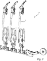
- Fig. 2 illustrates a device 9 for handling at least one fuel hose 7 in the fuel dispensing unit 1.
- the device 9 allows the at least one fuel hose 7 to be pulled out from a front opening of the hose storage space 2 and is adapted to return the at least one fuel hose 7 to the hose storage space 2.
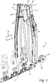
- the device 9 will now be described in greater detail according to one exemplary embodiment in view of Fig. 3 and 4 .
- Fig. 3 and Fig 4 illustrate the device 9 when in an idle position and when in a working position.
- the device 9 comprises a first hose guiding means 10 and a second hose hose guiding 11, which are both movable between an idle position and a working position to control extraction and infeed of the at least one fuel hose 7, a sensor means 12 arranged in hose storage space 2, a motor 13 connected to the second hose guiding 11 means through a cable element 14, and a control unit 15 connected to the sensor means 12 and to the motor 13.
- the control unit 15 is configured to control the motor 13 based on signals relating to the movements of the first hose guiding means 10 and/or the second hose guiding means 11 detected by the sensor means 12.
- the sensor means 12 comprises a first sensor 16 arranged in the hose storage space 2 and configured to detect the idle position the first hose guiding means 10, and a second sensor 17 arranged in the hose storage space 2 and configured to detect the working position the first hose guiding means 10.
- control unit 15 may be configured to trigger extraction of the cable element 14 by means of the motor 13 or to trigger a neutral state of the motor 13 when the working position of the first hose guiding means 10 is detected, and to trigger infeed of the cable element 14 by means of the motor 13 when the idle position of the first hose guiding means 10 is detected.
- control unit 15 may be configured to trigger extraction of the cable element 14 by means of the motor 13 or to trigger a neutral state of the motor 13 when at least a portion of the first hose guiding means 10 is detected outside of the hose storage space 2, and to trigger feeding in of the cable element 14 by means of the motor 13 the first hose guiding means 10 is detected inside of the hose storage space 2.
- the first hose guiding means 10 comprises a rocker unit which, to allow pulling out and returning of the hose 7, is pivotable in relation to the hose storage space 2 about a pivot axis 18 and which comprises a hose supporting part 19 which is arranged at a distance from the pivot axis 18 and adapted to support the hose 7.
- the rocker unit is adapted to be pivoted in a first direction when pulling out the hose 7 and, when returning the hose 7, be pivoted by a rocker returning means 20, constituted by a spring element which applies a returning force on the rocker unit at a distance from the pivot axis 18 in a second direction which is opposite to the first direction.
- the first hose guiding means 10 comprises a rail element to support the hose 7 which, to allow pulling out and returning of the hose 7, is movable in relation to the hose storage space 2 between in the idle position and the working position.
- the rail element is adapted to be moved towards the working position when pulling out the hose 7 and, when returning the hose 7, be moved towards the idle position.
- the sensor means 12 may for example comprise a two-way sensor instead which is capable of detecting a direction of the movement of the first hose guiding means 10.
- the control unit would be configured to trigger extraction of the cable element by means of the motor 13 or to trigger a neutral state of the motor when a first moving direction of the first hose guiding means 10 is detected, and to trigger infeed of the cable element by means of the motor 13 when a second moving direction of the first hose guiding means 10 is detected.
- the senor means 12 may be connected to a movable portion 21 of an outer housing 22 of the hose storage space 2, and the control unit 15 is configured to trigger extraction of the cable element 14 by means of the motor 13 or to trigger a neutral state of the motor 13 when movement of the movable portion 21 of the outer housing 22, in a direction away from the outer housing 22, is detected.
- the extraction of the cable element 14 by means of the motor 13 may be conducted based on a predetermined length of the cable element 14.
- the extraction of the cable element 14 by means of the motor 13 may be based on a motor driving power calculated by the control unit 15.
- the control unit 15 may be configured so that no infeed of the cable element 14 by means of the motor 13 is possible during refueling of a vehicle.
- the control unit 15 may be configured so that no extraction of the cable element 14 by means of the motor 13 is possible when the nozzle(s) 6 are present in the nozzle boot(s) 8.
- the control unit 15 may be configured so that no feeding of the cable element 14 by means of the motor 13 is possible when the fuel dispensing unit 1 is not released.
Landscapes
- Engineering & Computer Science (AREA)
- Mechanical Engineering (AREA)
- Loading And Unloading Of Fuel Tanks Or Ships (AREA)
Claims (12)
- Vorrichtung (9) zum Handhaben wenigstens eines Schlauchs (7), wobei die Vorrichtung (9) ermöglicht, dass der wenigstens eine Schlauch (7) aus einer vorderen Öffnung eines Schlauchstauraums (2) herausgezogen wird, und wobei die Vorrichtung (9) angepasst ist, um den wenigstens einen Schlauch (7) zu dem Schlauchstauraum (2) zurückzuführen, wobei die Vorrichtung (9) Folgendes umfasst:ein erstes Schlauch-Führungsmittel (10) und ein zweites Schlauch-Führungsmittel (11), die zwischen einer Ruhestellung und einer Arbeitsstellung beweglich sind, um den wenigstens einen Schlauch (7) zu steuern,ein Sensormittel (12), das in dem Schlauchstauraum (2) angeordnet ist,einen Motor (13), der mit dem zweiten Schlauch-Führungsmittel (11) durch ein Seilelement (14) verbunden ist, undeine Steuereinheit (15), die mit dem Sensormittel (12) und mit dem Motor (13) verbunden ist,wobei die Steuereinheit (15) dafür konfiguriert ist, den Motor (13) auf Grundlage von Signalen in Bezug auf die Bewegungen des ersten Schlauch-Führungsmittels (10) und/oder des zweiten Schlauch-Führungsmittels (11), die durch das Sensormittel (12) erfasst werden, zu steuern,dadurch gekennzeichnet, dass das Sensormittel (12) einen ersten Sensor (16), der in dem Schlauchstauraum (2) angeordnet und dafür konfiguriert ist, die Ruhestellung des ersten Schlauch-Führungsmittels (10) zu erfassen, und einen zweiten Sensor (17), der in dem Schlauchstauraum (2) angeordnet und dafür konfiguriert ist, die Arbeitsstellung des ersten Schlauch-Führungsmittels (10) zu erfassen, umfasst.
- Vorrichtung (9) nach Anspruch 1, wobei die Steuereinheit (15) dafür konfiguriert ist, ein Ausziehen des Seilelements (14) mit Hilfe des Motors (13) auszulösen oder einen neutralen Zustand des Motors (13) auszulösen, wenn die Arbeitsstellung des ersten Schlauch-Führungsmittels (10) erfasst wird, und ein Einziehen des Seilelements (14) mit Hilfe des Motors (13) auszulösen, wenn die Ruhestellung des ersten Schlauch-Führungsmittels (10) erfasst wird.
- Vorrichtung (9) nach Anspruch 1, wobei die Steuereinheit (15) dafür konfiguriert ist, ein Ausziehen des Seilelements (14) mit Hilfe des Motors (13) auszulösen oder einen neutralen Zustand des Motors (13) auszulösen, wenn wenigstens ein Abschnitt des ersten Schlauch-Führungsmittels (10) außerhalb des Schlauchstauraums (2) erfasst wird, und ein Einziehen des Seilelements (14) mit Hilfe des Motors (13) auszulösen, wenn das erste Schlauch-Führungsmittel (10) innerhalb des Schlauchstauraums (2) erfasst wird.
- Vorrichtung (9) nach einem der vorhergehenden Ansprüche, wobei das erste Schlauch-Führungsmittel (10) eine Kipphebeleinheit umfasst, die, um ein Herausziehen und Zurückführen des Schlauchs (7) zu ermöglichen, im Verhältnis zu dem Schlauchstauraum (2) um eine Schwenkachse (18) schwenkbar ist und die einen Schlauchstützteil (19) umfasst, der in einer Entfernung von der Schwenkachse (18) angeordnet und angepasst ist, um den Schlauch (7) zu stützen.
- Vorrichtung (9) nach Anspruch 4, wobei die Kipphebeleinheit angepasst ist, um in der ersten Richtung geschwenkt zu werden, wenn der Schlauch (7) herausgezogen wird und, wenn der Schlauch (7) zurückgeführt wird, durch ein Kipphebel-Rückführungsmittel (20) gekippt zu werden, das eine Rückführungskraft auf die Kipphebeleinheit in einer Entfernung von der Schwenkachse (18) in der zweiten Richtung, die zu der ersten Richtung entgegengesetzt ist, ausübt.
- Vorrichtung (9) nach Anspruch 4 oder 5, wobei das Kipphebel-Rückführungsmittel (20) ein Federelement umfasst.
- Vorrichtung (9) nach einem der Ansprüche 1 bis 4, wobei das erste Schlauch-Führungsmittel (10) ein Schienenelement umfasst, um den Schlauch (7) zu stützen, das, um ein Herausziehen und Zurückführen des Schlauchs (7) zu ermöglichen, in Verhältnis zu dem Schlauchstauraum (2) zwischen der Ruhestellung und der Arbeitsstellung beweglich ist.
- Vorrichtung (9) nach Anspruch 7, wobei das Schienenelement angepasst ist, um hin zu der Arbeitsstellung bewegt zu werden, wenn der Schlauch (7) herausgezogen wird, und, wenn der Schlauch (7) zurückgeführt wird, hin zu der Ruhestellung bewegt zu werden.
- Vorrichtung (9) nach einem der vorhergehenden Ansprüche, wobei das Sensormittel (12) ferner einen weiteren Sensor (23) umfasst, der dafür konfiguriert ist, eine Bewegung des zweiten Schlauch-Führungsmittels (11) zu erfassen, und die Steuereinheit (15) dafür konfiguriert ist, den Motor (13) anzuhalten, wenn sich das zweite Schlauch-Führungsmittel (11) in einer unteren Stellung innerhalb des Schlauchstauraums (2) befindet.
- Vorrichtung (9) nach einem der Ansprüche 1 oder 2, wobei das Ausziehen des Seilelements (14) mit Hilfe des Motors (13) für eine vorbestimmte Länge des Seilelements (14) durchgeführt wird.
- Vorrichtung (9) nach einem der Ansprüche 1 oder 2, wobei das Ausziehen des Seilelements (14) mit Hilfe des Motors (13) auf einer Motor-Antriebsleistung beruht, die durch die Steuereinheit (15) berechnet wird.
- Verfahren zum Handhaben wenigstens eines Schlauchs (7) in einer Kraftstoff-Abgabeeinheit (1), um zu ermöglichen, dass der wenigstens eine Schlauch (7) aus einer vorderen Öffnung eines Schlauchstauraums (2) herausgezogen wird, und um den wenigstens einen Schlauch (7) zu dem Schlauchstauraum (2) zurückzuführen, das die folgenden Schritte umfasst:Bereitstellen eines ersten Schlauch-Führungsmittels (10) und eines zweiten Schlauch-Führungsmittels (11), die zwischen einer Ruhestellung und einer Arbeitsstellung beweglich sind, um ein Ausziehen und ein Einziehen des Schlauchs (7) zu steuern,Anordnen eines Sensormittels (12) in dem Schlauchstauraum (2), wobei das Sensormittel (12) einen ersten Sensor (16), der in dem Schlauchstauraum (2) angeordnet und dafür konfiguriert ist, die Ruhestellung des ersten Schlauch-Führungsmittels (10) zu erfassen, und einen zweiten Sensor (17), der in dem Schlauchstauraum (2) angeordnet und dafür konfiguriert ist, die Arbeitsstellung des ersten Schlauch-Führungsmittels (10) zu erfassen, umfasst,gekennzeichnet durch den Schritt des Steuerns eines Motors (13), der mit dem zweiten Schlauch-Führungsmittel (11) durch ein Seilelement (14) verbunden ist, mit Hilfe einer Steuereinheit (15), die mit dem Sensormittel (12) und mit dem Motor (13) verbunden ist, auf Grundlage von erfassten Bewegungen des ersten Schlauch-Führungsmittels (10).
Applications Claiming Priority (2)
| Application Number | Priority Date | Filing Date | Title |
|---|---|---|---|
| SE1850544A SE543545C2 (en) | 2018-05-08 | 2018-05-08 | Device and method for handling at least one hose |
| PCT/EP2019/061687 WO2019215154A1 (en) | 2018-05-08 | 2019-05-07 | Fuel hose handling device with servo-motor |
Publications (2)
| Publication Number | Publication Date |
|---|---|
| EP3790835A1 EP3790835A1 (de) | 2021-03-17 |
| EP3790835B1 true EP3790835B1 (de) | 2022-03-30 |
Family
ID=66448559
Family Applications (1)
| Application Number | Title | Priority Date | Filing Date |
|---|---|---|---|
| EP19722877.8A Active EP3790835B1 (de) | 2018-05-08 | 2019-05-07 | Servounterstützte kraftstoffschlauch-handhabungseinrichtung |
Country Status (5)
| Country | Link |
|---|---|
| EP (1) | EP3790835B1 (de) |
| AU (1) | AU2019264801B2 (de) |
| PT (1) | PT3790835T (de) |
| SE (1) | SE543545C2 (de) |
| WO (1) | WO2019215154A1 (de) |
Families Citing this family (1)
| Publication number | Priority date | Publication date | Assignee | Title |
|---|---|---|---|---|
| CN112408309B (zh) * | 2020-12-14 | 2021-08-20 | 义乌市君胜科技有限公司 | 一种加油站用加油管缠绕装置 |
Citations (1)
| Publication number | Priority date | Publication date | Assignee | Title |
|---|---|---|---|---|
| EP0647587B1 (de) * | 1993-10-06 | 1996-04-10 | Scheidt & Bachmann Gmbh | Vorrichtung zur Abgabe von Kraftstoffen |
Family Cites Families (5)
| Publication number | Priority date | Publication date | Assignee | Title |
|---|---|---|---|---|
| GB782882A (en) | 1956-01-16 | 1957-09-11 | Gilbert & Barker Mfg Co | Swinging arm hose retriever for fluid dispensing apparatus |
| EP0640557B1 (de) * | 1993-08-24 | 1995-04-26 | Scheidt & Bachmann Gmbh | Vorrichtung zur Abgabe von Kraftstoffen |
| US6199579B1 (en) * | 1999-04-14 | 2001-03-13 | Dresser Equipment Group, Inc. | Hose handling system and method |
| US6328060B1 (en) | 2000-01-26 | 2001-12-11 | Dresser, Inc. | Gasoline dispensing unit and method with improved hose handling |
| SE518625C2 (sv) * | 2001-03-22 | 2002-10-29 | Dresser Wayne Ab | Anordning samt förfarande för hantering av en slang |
-
2018
- 2018-05-08 SE SE1850544A patent/SE543545C2/en not_active IP Right Cessation
-
2019
- 2019-05-07 AU AU2019264801A patent/AU2019264801B2/en active Active
- 2019-05-07 WO PCT/EP2019/061687 patent/WO2019215154A1/en not_active Ceased
- 2019-05-07 PT PT197228778T patent/PT3790835T/pt unknown
- 2019-05-07 EP EP19722877.8A patent/EP3790835B1/de active Active
Patent Citations (1)
| Publication number | Priority date | Publication date | Assignee | Title |
|---|---|---|---|---|
| EP0647587B1 (de) * | 1993-10-06 | 1996-04-10 | Scheidt & Bachmann Gmbh | Vorrichtung zur Abgabe von Kraftstoffen |
Also Published As
| Publication number | Publication date |
|---|---|
| WO2019215154A1 (en) | 2019-11-14 |
| SE543545C2 (en) | 2021-03-23 |
| SE1850544A1 (en) | 2019-11-09 |
| AU2019264801B2 (en) | 2022-09-29 |
| AU2019264801A1 (en) | 2020-12-10 |
| EP3790835A1 (de) | 2021-03-17 |
| PT3790835T (pt) | 2022-05-02 |
| BR112020022091A2 (pt) | 2021-02-02 |
Similar Documents
| Publication | Publication Date | Title |
|---|---|---|
| EP3286132B1 (de) | Vorrichtung zur handhabung von mindestens einem schlauch und zapfanlage für kraftstoff mit einer solchen vorrichtung | |
| US8230876B2 (en) | Apparatus for handling a hose | |
| EP2147892B1 (de) | Vorrichtung und Verfahren zur Handhabung eines Schlauchs und Brennstoffabgabeeinheit mit einer solchen Vorrichtung | |
| EP2163511B1 (de) | Vorrichtung zur Handhabung eines Schlauchs und Brennstoffabgabeeinheit mit einer solchen Vorrichtung | |
| US20180029873A1 (en) | Methods and Devices for Handling a Fuel Dispenser Hose | |
| AU2019264801B2 (en) | Fuel hose handling device with servo-motor | |
| EP1243549B1 (de) | Verfahren und Vorrichtung zur Handhabung eines Zapfschlauches | |
| EP3790834A1 (de) | Kraftstoffzapfsäule mit abgewinkelter zapfpistole | |
| EP2248761A1 (de) | Vorrichtung und Verfahren zur Handhabung von mindestens einem Schlauch und Brennstoffabgabeeinheit mit einer solchen Vorrichtung | |
| EP1253106B1 (de) | Vorrichtung und Verfahren zur Handhabung eines Schlauches | |
| EP1398294B1 (de) | Vorrichtung und Verfahren zum Handhaben eines Kraftstoffschlauchs | |
| EP2163512B1 (de) | Zapfpistolenaufnahme für eine Zapfsäule | |
| EP3790833B1 (de) | Motorgetriebene vorrichtung zur behandlung mehrerer schläuche in einer kraftstoffsäule | |
| EP3790836B1 (de) | Motorisierte vorrichtung zur handhabung eines oder mehrerer schläuche in einer kraftstoffzapfsäule | |
| EP2949619B1 (de) | Vorrichtung zur handhabung eines schlauchs und brennstoffabgabeeinheit mit solch einer vorrichtung | |
| SE544021C2 (en) | Device and method for handling at least one hose | |
| EP3988500A1 (de) | Verbesserte kraftstoffzapfeinheit | |
| EP1666407A1 (de) | Zapfsäule mit Ausschnitt im Seitenpaneel |
Legal Events
| Date | Code | Title | Description |
|---|---|---|---|
| STAA | Information on the status of an ep patent application or granted ep patent |
Free format text: STATUS: UNKNOWN |
|
| STAA | Information on the status of an ep patent application or granted ep patent |
Free format text: STATUS: THE INTERNATIONAL PUBLICATION HAS BEEN MADE |
|
| PUAI | Public reference made under article 153(3) epc to a published international application that has entered the european phase |
Free format text: ORIGINAL CODE: 0009012 |
|
| STAA | Information on the status of an ep patent application or granted ep patent |
Free format text: STATUS: REQUEST FOR EXAMINATION WAS MADE |
|
| 17P | Request for examination filed |
Effective date: 20201124 |
|
| AK | Designated contracting states |
Kind code of ref document: A1 Designated state(s): AL AT BE BG CH CY CZ DE DK EE ES FI FR GB GR HR HU IE IS IT LI LT LU LV MC MK MT NL NO PL PT RO RS SE SI SK SM TR |
|
| AX | Request for extension of the european patent |
Extension state: BA ME |
|
| DAV | Request for validation of the european patent (deleted) | ||
| DAX | Request for extension of the european patent (deleted) | ||
| GRAP | Despatch of communication of intention to grant a patent |
Free format text: ORIGINAL CODE: EPIDOSNIGR1 |
|
| STAA | Information on the status of an ep patent application or granted ep patent |
Free format text: STATUS: GRANT OF PATENT IS INTENDED |
|
| INTG | Intention to grant announced |
Effective date: 20211102 |
|
| GRAS | Grant fee paid |
Free format text: ORIGINAL CODE: EPIDOSNIGR3 |
|
| GRAA | (expected) grant |
Free format text: ORIGINAL CODE: 0009210 |
|
| STAA | Information on the status of an ep patent application or granted ep patent |
Free format text: STATUS: THE PATENT HAS BEEN GRANTED |
|
| AK | Designated contracting states |
Kind code of ref document: B1 Designated state(s): AL AT BE BG CH CY CZ DE DK EE ES FI FR GB GR HR HU IE IS IT LI LT LU LV MC MK MT NL NO PL PT RO RS SE SI SK SM TR |
|
| REG | Reference to a national code |
Ref country code: GB Ref legal event code: FG4D |
|
| REG | Reference to a national code |
Ref country code: CH Ref legal event code: EP |
|
| REG | Reference to a national code |
Ref country code: AT Ref legal event code: REF Ref document number: 1479047 Country of ref document: AT Kind code of ref document: T Effective date: 20220415 |
|
| REG | Reference to a national code |
Ref country code: DE Ref legal event code: R096 Ref document number: 602019013130 Country of ref document: DE |
|
| REG | Reference to a national code |
Ref country code: IE Ref legal event code: FG4D |
|
| REG | Reference to a national code |
Ref country code: PT Ref legal event code: SC4A Ref document number: 3790835 Country of ref document: PT Date of ref document: 20220502 Kind code of ref document: T Free format text: AVAILABILITY OF NATIONAL TRANSLATION Effective date: 20220427 |
|
| REG | Reference to a national code |
Ref country code: LT Ref legal event code: MG9D |
|
| PG25 | Lapsed in a contracting state [announced via postgrant information from national office to epo] |
Ref country code: SE Free format text: LAPSE BECAUSE OF FAILURE TO SUBMIT A TRANSLATION OF THE DESCRIPTION OR TO PAY THE FEE WITHIN THE PRESCRIBED TIME-LIMIT Effective date: 20220330 Ref country code: RS Free format text: LAPSE BECAUSE OF FAILURE TO SUBMIT A TRANSLATION OF THE DESCRIPTION OR TO PAY THE FEE WITHIN THE PRESCRIBED TIME-LIMIT Effective date: 20220330 Ref country code: NO Free format text: LAPSE BECAUSE OF FAILURE TO SUBMIT A TRANSLATION OF THE DESCRIPTION OR TO PAY THE FEE WITHIN THE PRESCRIBED TIME-LIMIT Effective date: 20220630 Ref country code: LT Free format text: LAPSE BECAUSE OF FAILURE TO SUBMIT A TRANSLATION OF THE DESCRIPTION OR TO PAY THE FEE WITHIN THE PRESCRIBED TIME-LIMIT Effective date: 20220330 Ref country code: HR Free format text: LAPSE BECAUSE OF FAILURE TO SUBMIT A TRANSLATION OF THE DESCRIPTION OR TO PAY THE FEE WITHIN THE PRESCRIBED TIME-LIMIT Effective date: 20220330 Ref country code: BG Free format text: LAPSE BECAUSE OF FAILURE TO SUBMIT A TRANSLATION OF THE DESCRIPTION OR TO PAY THE FEE WITHIN THE PRESCRIBED TIME-LIMIT Effective date: 20220630 |
|
| REG | Reference to a national code |
Ref country code: NL Ref legal event code: MP Effective date: 20220330 |
|
| REG | Reference to a national code |
Ref country code: AT Ref legal event code: MK05 Ref document number: 1479047 Country of ref document: AT Kind code of ref document: T Effective date: 20220330 |
|
| PG25 | Lapsed in a contracting state [announced via postgrant information from national office to epo] |
Ref country code: LV Free format text: LAPSE BECAUSE OF FAILURE TO SUBMIT A TRANSLATION OF THE DESCRIPTION OR TO PAY THE FEE WITHIN THE PRESCRIBED TIME-LIMIT Effective date: 20220330 Ref country code: GR Free format text: LAPSE BECAUSE OF FAILURE TO SUBMIT A TRANSLATION OF THE DESCRIPTION OR TO PAY THE FEE WITHIN THE PRESCRIBED TIME-LIMIT Effective date: 20220701 Ref country code: FI Free format text: LAPSE BECAUSE OF FAILURE TO SUBMIT A TRANSLATION OF THE DESCRIPTION OR TO PAY THE FEE WITHIN THE PRESCRIBED TIME-LIMIT Effective date: 20220330 |
|
| PG25 | Lapsed in a contracting state [announced via postgrant information from national office to epo] |
Ref country code: NL Free format text: LAPSE BECAUSE OF FAILURE TO SUBMIT A TRANSLATION OF THE DESCRIPTION OR TO PAY THE FEE WITHIN THE PRESCRIBED TIME-LIMIT Effective date: 20220330 |
|
| PG25 | Lapsed in a contracting state [announced via postgrant information from national office to epo] |
Ref country code: SM Free format text: LAPSE BECAUSE OF FAILURE TO SUBMIT A TRANSLATION OF THE DESCRIPTION OR TO PAY THE FEE WITHIN THE PRESCRIBED TIME-LIMIT Effective date: 20220330 Ref country code: SK Free format text: LAPSE BECAUSE OF FAILURE TO SUBMIT A TRANSLATION OF THE DESCRIPTION OR TO PAY THE FEE WITHIN THE PRESCRIBED TIME-LIMIT Effective date: 20220330 Ref country code: RO Free format text: LAPSE BECAUSE OF FAILURE TO SUBMIT A TRANSLATION OF THE DESCRIPTION OR TO PAY THE FEE WITHIN THE PRESCRIBED TIME-LIMIT Effective date: 20220330 Ref country code: ES Free format text: LAPSE BECAUSE OF FAILURE TO SUBMIT A TRANSLATION OF THE DESCRIPTION OR TO PAY THE FEE WITHIN THE PRESCRIBED TIME-LIMIT Effective date: 20220330 Ref country code: EE Free format text: LAPSE BECAUSE OF FAILURE TO SUBMIT A TRANSLATION OF THE DESCRIPTION OR TO PAY THE FEE WITHIN THE PRESCRIBED TIME-LIMIT Effective date: 20220330 Ref country code: CZ Free format text: LAPSE BECAUSE OF FAILURE TO SUBMIT A TRANSLATION OF THE DESCRIPTION OR TO PAY THE FEE WITHIN THE PRESCRIBED TIME-LIMIT Effective date: 20220330 Ref country code: AT Free format text: LAPSE BECAUSE OF FAILURE TO SUBMIT A TRANSLATION OF THE DESCRIPTION OR TO PAY THE FEE WITHIN THE PRESCRIBED TIME-LIMIT Effective date: 20220330 |
|
| PG25 | Lapsed in a contracting state [announced via postgrant information from national office to epo] |
Ref country code: PL Free format text: LAPSE BECAUSE OF FAILURE TO SUBMIT A TRANSLATION OF THE DESCRIPTION OR TO PAY THE FEE WITHIN THE PRESCRIBED TIME-LIMIT Effective date: 20220330 Ref country code: IS Free format text: LAPSE BECAUSE OF FAILURE TO SUBMIT A TRANSLATION OF THE DESCRIPTION OR TO PAY THE FEE WITHIN THE PRESCRIBED TIME-LIMIT Effective date: 20220730 Ref country code: AL Free format text: LAPSE BECAUSE OF FAILURE TO SUBMIT A TRANSLATION OF THE DESCRIPTION OR TO PAY THE FEE WITHIN THE PRESCRIBED TIME-LIMIT Effective date: 20220330 |
|
| REG | Reference to a national code |
Ref country code: CH Ref legal event code: PL |
|
| REG | Reference to a national code |
Ref country code: DE Ref legal event code: R097 Ref document number: 602019013130 Country of ref document: DE |
|
| REG | Reference to a national code |
Ref country code: BE Ref legal event code: MM Effective date: 20220531 |
|
| PG25 | Lapsed in a contracting state [announced via postgrant information from national office to epo] |
Ref country code: MC Free format text: LAPSE BECAUSE OF FAILURE TO SUBMIT A TRANSLATION OF THE DESCRIPTION OR TO PAY THE FEE WITHIN THE PRESCRIBED TIME-LIMIT Effective date: 20220330 Ref country code: LU Free format text: LAPSE BECAUSE OF NON-PAYMENT OF DUE FEES Effective date: 20220507 Ref country code: LI Free format text: LAPSE BECAUSE OF NON-PAYMENT OF DUE FEES Effective date: 20220531 Ref country code: DK Free format text: LAPSE BECAUSE OF FAILURE TO SUBMIT A TRANSLATION OF THE DESCRIPTION OR TO PAY THE FEE WITHIN THE PRESCRIBED TIME-LIMIT Effective date: 20220330 Ref country code: CH Free format text: LAPSE BECAUSE OF NON-PAYMENT OF DUE FEES Effective date: 20220531 |
|
| PLBE | No opposition filed within time limit |
Free format text: ORIGINAL CODE: 0009261 |
|
| STAA | Information on the status of an ep patent application or granted ep patent |
Free format text: STATUS: NO OPPOSITION FILED WITHIN TIME LIMIT |
|
| 26N | No opposition filed |
Effective date: 20230103 |
|
| PG25 | Lapsed in a contracting state [announced via postgrant information from national office to epo] |
Ref country code: IE Free format text: LAPSE BECAUSE OF NON-PAYMENT OF DUE FEES Effective date: 20220507 |
|
| PG25 | Lapsed in a contracting state [announced via postgrant information from national office to epo] |
Ref country code: SI Free format text: LAPSE BECAUSE OF FAILURE TO SUBMIT A TRANSLATION OF THE DESCRIPTION OR TO PAY THE FEE WITHIN THE PRESCRIBED TIME-LIMIT Effective date: 20220330 Ref country code: BE Free format text: LAPSE BECAUSE OF NON-PAYMENT OF DUE FEES Effective date: 20220531 |
|
| P01 | Opt-out of the competence of the unified patent court (upc) registered |
Effective date: 20230529 |
|
| PG25 | Lapsed in a contracting state [announced via postgrant information from national office to epo] |
Ref country code: IT Free format text: LAPSE BECAUSE OF FAILURE TO SUBMIT A TRANSLATION OF THE DESCRIPTION OR TO PAY THE FEE WITHIN THE PRESCRIBED TIME-LIMIT Effective date: 20220330 |
|
| PG25 | Lapsed in a contracting state [announced via postgrant information from national office to epo] |
Ref country code: MK Free format text: LAPSE BECAUSE OF FAILURE TO SUBMIT A TRANSLATION OF THE DESCRIPTION OR TO PAY THE FEE WITHIN THE PRESCRIBED TIME-LIMIT Effective date: 20220330 Ref country code: CY Free format text: LAPSE BECAUSE OF FAILURE TO SUBMIT A TRANSLATION OF THE DESCRIPTION OR TO PAY THE FEE WITHIN THE PRESCRIBED TIME-LIMIT Effective date: 20220330 |
|
| PG25 | Lapsed in a contracting state [announced via postgrant information from national office to epo] |
Ref country code: HU Free format text: LAPSE BECAUSE OF FAILURE TO SUBMIT A TRANSLATION OF THE DESCRIPTION OR TO PAY THE FEE WITHIN THE PRESCRIBED TIME-LIMIT; INVALID AB INITIO Effective date: 20190507 |
|
| PG25 | Lapsed in a contracting state [announced via postgrant information from national office to epo] |
Ref country code: MT Free format text: LAPSE BECAUSE OF FAILURE TO SUBMIT A TRANSLATION OF THE DESCRIPTION OR TO PAY THE FEE WITHIN THE PRESCRIBED TIME-LIMIT Effective date: 20220330 |
|
| PGFP | Annual fee paid to national office [announced via postgrant information from national office to epo] |
Ref country code: DE Payment date: 20250528 Year of fee payment: 7 |
|
| PGFP | Annual fee paid to national office [announced via postgrant information from national office to epo] |
Ref country code: GB Payment date: 20250520 Year of fee payment: 7 |
|
| PGFP | Annual fee paid to national office [announced via postgrant information from national office to epo] |
Ref country code: PT Payment date: 20250428 Year of fee payment: 7 |
|
| PGFP | Annual fee paid to national office [announced via postgrant information from national office to epo] |
Ref country code: FR Payment date: 20250526 Year of fee payment: 7 |
|
| PG25 | Lapsed in a contracting state [announced via postgrant information from national office to epo] |
Ref country code: TR Free format text: LAPSE BECAUSE OF FAILURE TO SUBMIT A TRANSLATION OF THE DESCRIPTION OR TO PAY THE FEE WITHIN THE PRESCRIBED TIME-LIMIT Effective date: 20220330 |