EP3791010B1 - Core/shell-vacancy engineering (csve) of catalysts for electrochemical co2 reduction - Google Patents
Core/shell-vacancy engineering (csve) of catalysts for electrochemical co2 reduction Download PDFInfo
- Publication number
- EP3791010B1 EP3791010B1 EP19724761.2A EP19724761A EP3791010B1 EP 3791010 B1 EP3791010 B1 EP 3791010B1 EP 19724761 A EP19724761 A EP 19724761A EP 3791010 B1 EP3791010 B1 EP 3791010B1
- Authority
- EP
- European Patent Office
- Prior art keywords
- core
- shell
- carbon
- catalyst
- catalyst system
- Prior art date
- Legal status (The legal status is an assumption and is not a legal conclusion. Google has not performed a legal analysis and makes no representation as to the accuracy of the status listed.)
- Active
Links
Images





Classifications
-
- H—ELECTRICITY
- H01—ELECTRIC ELEMENTS
- H01M—PROCESSES OR MEANS, e.g. BATTERIES, FOR THE DIRECT CONVERSION OF CHEMICAL ENERGY INTO ELECTRICAL ENERGY
- H01M4/00—Electrodes
- H01M4/86—Inert electrodes with catalytic activity, e.g. for fuel cells
- H01M4/90—Selection of catalytic material
-
- C—CHEMISTRY; METALLURGY
- C25—ELECTROLYTIC OR ELECTROPHORETIC PROCESSES; APPARATUS THEREFOR
- C25B—ELECTROLYTIC OR ELECTROPHORETIC PROCESSES FOR THE PRODUCTION OF COMPOUNDS OR NON-METALS; APPARATUS THEREFOR
- C25B11/00—Electrodes; Manufacture thereof not otherwise provided for
- C25B11/04—Electrodes; Manufacture thereof not otherwise provided for characterised by the material
- C25B11/051—Electrodes formed of electrocatalysts on a substrate or carrier
- C25B11/073—Electrodes formed of electrocatalysts on a substrate or carrier characterised by the electrocatalyst material
- C25B11/091—Electrodes formed of electrocatalysts on a substrate or carrier characterised by the electrocatalyst material consisting of at least one catalytic element and at least one catalytic compound; consisting of two or more catalytic elements or catalytic compounds
-
- C—CHEMISTRY; METALLURGY
- C25—ELECTROLYTIC OR ELECTROPHORETIC PROCESSES; APPARATUS THEREFOR
- C25B—ELECTROLYTIC OR ELECTROPHORETIC PROCESSES FOR THE PRODUCTION OF COMPOUNDS OR NON-METALS; APPARATUS THEREFOR
- C25B11/00—Electrodes; Manufacture thereof not otherwise provided for
- C25B11/04—Electrodes; Manufacture thereof not otherwise provided for characterised by the material
- C25B11/042—Electrodes formed of a single material
-
- C—CHEMISTRY; METALLURGY
- C25—ELECTROLYTIC OR ELECTROPHORETIC PROCESSES; APPARATUS THEREFOR
- C25B—ELECTROLYTIC OR ELECTROPHORETIC PROCESSES FOR THE PRODUCTION OF COMPOUNDS OR NON-METALS; APPARATUS THEREFOR
- C25B3/00—Electrolytic production of organic compounds
- C25B3/20—Processes
- C25B3/25—Reduction
- C25B3/26—Reduction of carbon dioxide
-
- B—PERFORMING OPERATIONS; TRANSPORTING
- B01—PHYSICAL OR CHEMICAL PROCESSES OR APPARATUS IN GENERAL
- B01J—CHEMICAL OR PHYSICAL PROCESSES, e.g. CATALYSIS OR COLLOID CHEMISTRY; THEIR RELEVANT APPARATUS
- B01J27/00—Catalysts comprising the elements or compounds of halogens, sulfur, selenium, tellurium, phosphorus or nitrogen; Catalysts comprising carbon compounds
- B01J27/02—Sulfur, selenium or tellurium; Compounds thereof
- B01J27/04—Sulfides
- B01J27/043—Sulfides with iron group metals or platinum group metals
-
- Y—GENERAL TAGGING OF NEW TECHNOLOGICAL DEVELOPMENTS; GENERAL TAGGING OF CROSS-SECTIONAL TECHNOLOGIES SPANNING OVER SEVERAL SECTIONS OF THE IPC; TECHNICAL SUBJECTS COVERED BY FORMER USPC CROSS-REFERENCE ART COLLECTIONS [XRACs] AND DIGESTS
- Y02—TECHNOLOGIES OR APPLICATIONS FOR MITIGATION OR ADAPTATION AGAINST CLIMATE CHANGE
- Y02E—REDUCTION OF GREENHOUSE GAS [GHG] EMISSIONS, RELATED TO ENERGY GENERATION, TRANSMISSION OR DISTRIBUTION
- Y02E60/00—Enabling technologies; Technologies with a potential or indirect contribution to GHG emissions mitigation
- Y02E60/30—Hydrogen technology
- Y02E60/50—Fuel cells
-
- Y—GENERAL TAGGING OF NEW TECHNOLOGICAL DEVELOPMENTS; GENERAL TAGGING OF CROSS-SECTIONAL TECHNOLOGIES SPANNING OVER SEVERAL SECTIONS OF THE IPC; TECHNICAL SUBJECTS COVERED BY FORMER USPC CROSS-REFERENCE ART COLLECTIONS [XRACs] AND DIGESTS
- Y02—TECHNOLOGIES OR APPLICATIONS FOR MITIGATION OR ADAPTATION AGAINST CLIMATE CHANGE
- Y02P—CLIMATE CHANGE MITIGATION TECHNOLOGIES IN THE PRODUCTION OR PROCESSING OF GOODS
- Y02P20/00—Technologies relating to chemical industry
- Y02P20/10—Process efficiency
- Y02P20/133—Renewable energy sources, e.g. sunlight
Definitions
- the technical field generally relates to catalytic methods for CO 2 reduction, and more particularly to electrocatalysts having a core-shell structure and associated methods for electrochemical CO 2 reduction.
- CO 2 carbon dioxide
- a technology that enhances such a conversion can, for example, enable the storage of intermittent renewable electricity as well as net reductions of greenhouse gas emissions.
- Existing catalyst systems for such CO 2 reduction processes have a number of drawbacks, including low selectivity for producing certain compounds.
- Cu2-xS micro-/nanostructures comprising core-shell structures with a metal core (such as Au core or CuO core) and one or more Cu 2 S shells
- a metal core such as Au core or CuO core
- Cu 2 S shells The diversified Cu 2 -xS micro-/nanostructures apply in the fields of photocatalyst, energy conversion, in vitro biosensor and in vivo imaging and therapy.
- the catalyst system can have a core-shell structure, with a core that includes metal sulphide (preferably copper sulphide) material, and a shell enveloping the core and comprising a metal (preferably copper) material with vacancies.
- the catalyst system can include nanoparticles having the core-shell structure and can be made in situ by deploying a catalyst precursor that is made of vacancy enriched metal sulphide particles having an external layer that is reduceable in situ to form reduced metallic shells with enriched vacancies surrounding the corresponding metal sulphide cores.
- One advantageous feature of the catalyst systems is a notably enhanced selectivity to multi-carbon alcohol production from CO 2 .
- the invention provides a catalyst system for electrocatalyzing conversion of CO 2 into multi-carbon hydrocarbons and/or alcohols, remarkable in that it comprises a core-shell structure comprising a core that is composed of a metal sulphide and a shell having a lower sulphur content than the core and that is composed of a metal with vacancies; in that the metal of the core and the metal of the shell are the same metal; and in that the shell has a thickness that is ranging between 1 nm to 3 nm as determined by EDS line scan measurement, wherein EDS line scan is carried out using a JEM-ARM 200F Atomic Resolution Analytical Microscope operating at an accelerating voltage of 200 kV.
- a catalyst system comprising core-shell particles wherein the core comprises sulphur atoms and the shell comprises intentional vacancies is able to block the reaction pathway for ethylene.
- the catalyst system of the invention allows the ratio of alcohol-to-ethylene to be increased by over 6 times compared to relative bare-copper nanoparticles, highlighting a new approach to electro- chemically produce alcohols instead of alkenes.
- C2+ alcohol production rate of 126 mA cm -2 was achieved with a selectivity of 32% Faradaic efficiency (FE). This represents a 1.6 times enhancement over the highest previously-reported current density for multi-carbon alcohols.
- FE Faradaic efficiency
- the core-shell structure is core-shell particles.
- the definition of the catalyst system reads: a catalyst system for electrocatalyzing conversion of CO 2 into multi-carbon hydrocarbons and/or alcohols, comprising core-shell particles comprising a core that is composed of a metal sulphide and a shell that is composed of a metal with vacancies.
- the core-shell structure is a layered material.
- the definition of the catalyst system reads: a catalyst system for electrocatalyzing conversion of CO 2 into multi-carbon hydrocarbons, comprising: an outer layer comprising a metal material with vacancies and being exposable to CO 2 , and an inner material covered by the outer layer and comprising a catalytic metal and a secondary non-metal compound; with preference, the inner material is a metal sulphide.
- the definition of the catalyst may read: a catalyst system for electrocatalyzing conversion of CO 2 into multi-carbon hydrocarbons and/or alcohols, comprising a core-shell layered material comprising an inner layer forming a core that is composed of a metal sulphide, and an outer layer forming a shell that is composed of a metal with vacancies.
- the layered material has a thickness ranging between 1 nm and 30 nm, preferably between 2 nm and 20 nm, more preferably between 3 nm and 15 nm, even more preferably between 4 nm and 12 nm, and most preferably between 5 and 10 nm.
- the thickness of the layered material is determined by EDS line scan measurement wherein the EDS line scan is carried out using a JEM-ARM 200F Atomic Resolution Analytical Microscope operating at an accelerating voltage of 200 kV.
- the invention relates to a method for electrochemical production of a multi-carbon alcohol, comprising the steps of:
- the method further comprises a step of deploying a catalyst system precursor comprising copper sulphide particles in the electrolyte and applying the voltage to:
- the invention provides the use of the catalyst system as defined in the first aspect in the electrochemical production of at least one multi-carbon alcohol.
- the invention provides the use of the catalyst system as defined in the first aspect in the electrochemical production of at least one multi-carbon hydrocarbon; with preference, the at least one multi-carbon hydrocarbon comprises ethylene.
- the invention provides a method of manufacturing a catalyst system comprising core-shell particles for electrocatalyzing conversion of CO 2 into multi-carbon hydrocarbons and/or alcohols, the method comprising the following steps:
- the method further comprises a step of washing the collected particles and then drying the washed particles.
- the washing is performed with acetone and hexane, and the drying is performed under vacuum conditions.
- the step of preparing of the particles comprises the following sub-steps:
- the invention provides the use of the catalyst system as defined according to the first aspect of the invention in a fuel cell.
- the invention provides a catalyst precursor for deployment in an electrocatalysis unit for in situ formation of a catalyst system for conversion of CO 2 into multi-carbon alcohols, the catalyst precursor comprising vacancy enriched metal sulphide nanoparticles having an external layer that is reduceable in situ to form reduced metallic shells with enriched vacancies surrounding corresponding metal sulphide cores, wherein the metal is copper, wherein the vacancy enriched metal sulphide nanoparticles have a covellite structure and have an overall Cu/S molar ratio ranging between 1 and 3 by XRF-1800 quantitative analysis with a 4 kW Thin-window X-ray Tube; wherein the vacancy enriched metal sulphide nanoparticles have a generally spherical shape and an average diameter ranging between 3 nm and 30 nm as determined by transmission electron microscopy (TEM).
- TEM transmission electron microscopy
- the invention provides the use of the catalyst precursor as defined in the seventh aspect, in an electrocatalysis operation for conversion of CO 2 into multi-carbon alcohols; preferably the multi-carbon alcohols comprise ethanol and/or propanol.
- the invention provides a system for CO 2 electroreduction to produce multi-carbon hydrocarbons, comprising:
- the electrolytic cell is configured to be operable at conditions that maximize production of multi-carbon alcohols.
- the invention provides a method for electrochemical production of a multi-carbon hydrocarbon, comprising:
- the invention also provides a method for electrochemical production of a multi-carbon hydrocarbon, comprising:
- the negative potential that is applied is pre-determined in accordance with selective production of a target multi-carbon hydrocarbon.
- Electrochemical reduction of CO 2 into value-added carbon-based products addresses the need for long-term storage of renewable electricity.
- Liquid multi-carbon alcohols such as ethanol and n-propanol, are highly desired as renewable transportation fuels. They offer high energy densities, ease of long-range transport, and direct usage.
- the invention explored positive factors to switch CO 2 reduction reaction pathways from ethylene to alcohol production.
- the invention engineered a new catalyst that efficiently electrochemically reduces CO 2 to n-propanol and ethanol.
- the invention provides a catalyst system for electrocatalyzing conversion of CO 2 into multi-carbon hydrocarbons and/or multi-carbon alcohols, comprising a core-shell structure comprising a core that is composed of a metal sulphide and a shell that is composed of a metal with vacancies.
- the multi-carbon hydrocarbons are, or preferably comprise ethylene.
- the multi-carbon alcohols are, or comprise, ethanol and/or propanol.
- the catalyst system can include a core comprising a catalytic metal (e.g., copper) and a modifier (e.g., sulphur atoms), and a shell enveloping the core and comprising a catalytic metal (e.g., copper) with intentional vacancies.
- a catalytic metal e.g., copper
- a modifier e.g., sulphur atoms
- a shell enveloping the core and comprising a catalytic metal (e.g., copper) with intentional vacancies.
- the core-bound sulphur atoms particularly in combination with the surface Cu vacancy, increase the energy barrier of post C-C coupling towards ethylene production while leaving the ethanol pathway generally unaffected, compared to that of the pure Cu catalyst.
- the designed Cu 2 S/Cu-V core/shell-vacancy catalyst provides a shift selectivity for alcohols.
- the core-shell particle of the invention causes modulation in branching in favour of ethanol relative to ethylene.
- the metal of the core and the metal of the shell are the same metal; with preference, the metal of the core and the metal of the shell are copper.
- the metal sulphide of the core is copper sulphide and the metal of the shell is copper.
- the shell has a lower sulphur content than the core.
- the shell is substantially depleted in sulphur.
- the catalyst comprises copper and sulphur and copper and sulphur are distributed evenly throughout the core.
- the V-Cu 2 S nanoparticles with non-stoichiometric Cu is first synthesized, and then the nanoparticle to produce the Cu 2 S/Cu-V structure is partially reduced.
- the surface metal is the active species over the electrocatalysis.
- the designed metal sulphide core affects the electronic properties of the surface metal and thereby the post C-C coupling intermediates and the following reaction pathway toward the production of multi-carbon alcohols over CO 2 reduction.
- copper and sulphur are present in a non-stoichiometric ratio
- the Cu 2 S/Cu-V core/shell vacancy catalyst is produced through partially reducing the V-Cu 2 S nanoparticles.
- the Cu and S of the V-Cu 2 S nanoparticles present in a non-stoichiometric ratio. After the initial electroreduction, the surface is reduced to the metallic Cu with vacancy while the core changed to stoichiometric Cu 2 S.
- the designed metal sulphide core and the surface vacancy synergistically affect the electronic properties of the surface metal and thereby the post C-C coupling intermediates and the following reaction pathway toward the production of multi-carbon alcohols over CO 2 reduction.
- the core comprises, or consists of, a djurleite phase.
- a djurleite phase As it is known to the person skilled in the art, for compositions near Cu 2 S a number of phases exist at room temperature. These may be divided into two broad categories based on the nature of the sulphur close-packing in the structure. The first category comprises chalcocite and djurleite with structures based on hexagonal close-packing of sulphur atoms. The second category comprises digenite-like structures and anilite with sulphur atoms in approximately cubic close-packing. The structure of the core as a djurleite phase can be determined by transmission electron microscopy.
- the core has a covellite structure.
- the initial V-Cu 2 S has a djurleite phase; while the core of the final Cu 2 S/Cu-V core/shell vacancy catalyst has a chalcocite phase.
- the core and shell have an overall Cu/S molar ratio ranging between 3 and 7 as determined by XRF-1800 quantitative analysis with a 4 kW Thin-window X-ray Tube, preferably between 4 and 6, and more preferably between 4.5 and 5.5.
- examples of the shell-core catalyst systems described herein can include other elements besides sulphur and copper, such as oxygen and tin.
- the catalyst system of the invention can have a variety of properties and features.
- the catalyst system can take the form of a catalytic material that includes core-shell particles, with copper sulphide core and copper-with-vacancies shell.
- Other structures are also possible, such as a material that includes an outer copper-with-vacancies layer and an inner copper sulphide material, and thus does not necessarily have a particle structure that is the same as the shell-core particles.
- the catalyst system can have certain physical properties, such as the size of the core and shell, and the compositions of the core and shell.
- a catalyst system for the electroreduction of CO 2 into alcohols can have a core/shell structure designed to provide and leverage certain vacancy properties to the catalyst system.
- the catalyst system can include a nanoparticle core comprising sulphur atoms and a shell comprising intentional copper vacancies, to block the reaction pathway for ethylene.
- This innovative core/shell-vacancy engineering (CSVE) strategy for the catalyst system generally increases the reaction barrier to ethylene without affecting the path for alcohols.
- the catalyst system (which can also be referred to as the electrocatalyst, as in Figure 3a ) includes a Cu 2 S core and a Cu-V shell for enhanced electrocatalytic conversion of CO 2 into liquid alcohols.
- the catalyst system is in the form of core-shell particles.
- the core-shell particles are nanoparticles, with preference the nanoparticles have a spherical shape.
- the nanoparticles have an average diameter ranging from 1 nm to 30 nm as determined by transmission electron microscopy (TEM), preferably from 2 nm to 20 nm, more preferably from 3 nm to 15 nm, even more preferably from 4 nm to 12 nm, and most preferably from 5 to 10 nm.
- TEM transmission electron microscopy
- the shell has a thickness that is smaller than the diameter of the core.
- the shell has a thickness that is between 2 to 4 times smaller than a diameter of the core, preferably 2.5 to 3.5 times smaller than a diameter of the core, or 3 times smaller than a diameter of the core.
- the catalyst system comprises colloidal nanoparticles dispersed in a medium of suspension, such as in methanol.
- the core-shell structure is a core-shell layered material comprising an inner layer forming a core and an outer layer forming a shell.
- the layered material has a thickness ranging between 1 nm and 30 nm, preferably between 2 nm and 20 nm as determined by EDS line scan measurement, wherein EDS line scan is carried out using a JEM-ARM 200F Atomic Resolution Analytical Microscope operating at an accelerating voltage of 200 kV, more preferably between 3 nm and 15 nm, even more preferably between 4 nm and 12 nm, and most preferably between 5 and 10 nm
- the shell has a thickness ranging from 1 nm to 3 nm as determined by EDS line scan measurement, wherein EDS line scan is carried out using a JEM-ARM 200F Atomic Resolution Analytical Microscope operating at an accelerating voltage of 200 kV, preferably from 1.5 nm to 2.5 nm, and more preferably from 1.75 nm to 2.25 nm.
- shell-core catalyst system described herein can be used as a catalyst layer in a composite multilayered electrocatalyst (CME) that includes a polymer-based gas-diffusion layer, a current collection structure, and the catalyst layer sandwiched in between.
- CME composite multilayered electrocatalyst
- the current collection structure can include a carbon nanoparticle layer applied against the catalyst layer, and a graphite layer applied against the nanoparticle layer.
- the CME includes a hydrophobic polymer-based support such as polytetrafluoroethylene (PTFE); a shell-core catalyst system material deposited on top; a layer of carbon-based nanoparticles (NPs) atop the catalyst; and an ensuing layer of graphite as the electron conductive layer.
- PTFE polytetrafluoroethylene
- NPs carbon-based nanoparticles
- the PTFE layer which can substantially be pure PTFE or similar polymer, acts as a more stable hydrophobic gas-diffusion layer that prevents flooding from the catholyte; carbon NPs and graphite stabilize the metal catalyst surface; the graphite layer serves both as an overall support and current collector.
- the CME includes a hydrophobic polymer-based layer; the shell-core catalyst material deposited on top; and then a layer of conductive material such as graphite deposited on top of the catalyst layer.
- the stabilization material e.g., carbon nanoparticles
- the stabilization material is not present as a distinct layer in between the graphite and the catalyst layers.
- Other features of the CME and related CO 2 RR methods as described in Nature Catalyst 2018, 1, 421-428 can be used in combination with the catalyst system and methods described herein.
- the invention encompasses a system for CO 2 electroreduction to produce multi-carbon hydrocarbons, comprising:
- the electrolytic cell is configured to be operable at conditions that maximize production of multi-carbon alcohols.
- the invention also relates to the use of the catalyst system according to the invention in a fuel cell.
- the shell is preferably formed by subjecting a vacancy enriched copper sulphide particle to reduction, thereby releasing sulphur from an external layer of the particle and forming the shell depleted in sulphur while retaining the sulphur in the core.
- the invention also contemplates a method of manufacturing a catalyst system comprising core-shell particles for electrocatalyzing conversion of CO 2 into multi-carbon hydrocarbons and/or alcohols, the method comprising the following steps:
- the catalyst system is as described above.
- the particles that are prepared are nanoparticles; with preference, the nanoparticles are colloidal nanoparticles.
- the prepared nanoparticles are composed of copper sulphide.
- the particles are prepared using a solvothermal method.
- the step of preparing the particles comprises the following sub-steps:
- Cu (acac)2 is Copper(II) acetylacetonate (CAS Number 13395-16-9) and is commercially available at Merck.
- the solvent is selected from thiols; for example, the solvent is dodecanethiol
- thiols is advantageous as thiols can serve as the solvent and the sulphur source.
- the heating is performed at a temperature ranging from 230 to 250°C for a duration lasting from 15 to 25 minutes.
- the reaction mixture is subjected to mixing during the heating step, with preference under the protection of an inert gas such as nitrogen gas or argon.
- the resulting nanoparticles are collected by centrifugation.
- the step of preparing the particles comprises a sub-step of washing the collected particles and then drying the washed particles. For instance, the washing is performed with acetone and hexane, and the drying is performed under vacuum conditions.
- the reduction of the particles comprises electroreduction by contacting the particles with CO 2 saturated electrolyte and applying a voltage to provide a current density to cause CO 2 gas contacting the particles to be electrochemically converted into the multi-carbon hydrocarbon.
- the electrolyte comprises an alkaline KOH electrolyte.
- the electroreduction is performed in a two-compartment electrochemical H-cell with a proton exchange membrane as a separator and a flow-cell configuration comprising a gas-diffusion layer with an anion exchange membrane.
- the electroreduction is preferably conducted for at least 1 minute, more preferably for at least 2 minutes, even more preferably for at least 3 minutes, most preferably for at least 4 minutes, even most preferably for at least 5 minutes.
- the electroreduction is preferably conducted for a time ranging from 1 min to 6 minutes, preferably ranging from 2 to 5 minutes.
- the catalyst system can also be made by preparing a catalyst precursor material or particles that are made of vacancy enriched metal sulphide material having an external layer that is reduceable in situ to form reduced metallic external layers with enriched vacancies coating or surrounding corresponding metal sulphide material.
- the core-shell catalyst system can be formed in situ.
- the electroreduction is performed in an electroreduction unit that is subsequently used to produce the multi-carbon hydrocarbons such that the core-shell particles are formed in situ.
- the catalyst precursor is the catalyst precursor of the catalyst precursor
- the invention also provides a catalyst precursor for deployment in an electrocatalysis unit for in situ formation of a catalyst system for conversion of CO 2 into multi-carbon hydrocarbons, the catalyst precursor comprising vacancy enriched metal sulphide nanoparticles having an external layer that is reduceable in situ to form reduced metallic shells with enriched vacancies surrounding the corresponding metal sulphide cores.
- the multi-carbon hydrocarbons comprise multi-carbon alcohols, such as ethanol and/or propanol.
- the vacancy enriched metal sulphide nanoparticles are formed by dissolving Cu (acac)2 in a solvent to form a reaction mixture, heating the reaction mixture to form the nanoparticles; collecting the nanoparticles from the reaction mixture.
- the vacancy enriched metal sulphide nanoparticles have an average diameter ranging from 3 nm to 30 nm as determined by transmission electron microscopy (TEM), preferably from 3 nm to 20 nm, more preferably from 3 nm to 15 nm, even more preferably from 4 nm to 12 nm, and most preferably from 5 to 10 nm.
- TEM transmission electron microscopy
- the vacancy enriched metal sulphide nanoparticles have a generally spherical shape. They comprise have a covellite structure and preferably a djurleite phase.
- the vacancy enriched metal sulphide nanoparticles have an overall Cu/S molar ratio ranging between 1 and 3 as determined by XRF-1800 quantitative analysis with a 4 kW Thin-window X-ray Tube. Indeed, the vacancy enriched metal sulphide is the initial nanoparticle without electroreduction.
- the molar ratio of Cu/S is therefore between 1 and 3.
- the surface V-Cu 2 S is reduced to metallic Cu, the ratio of Cu/S increases therefore between 3 and 7.
- the metal is a catalytic metal, preferably the metal is copper.
- the metal and sulphur atoms are advantageously distributed evenly throughout the vacancy enriched metal sulphide nanoparticles.
- the invention also encompasses the use of the catalyst precursor as defined above, in an electrocatalysis operation for conversion of CO 2 into multi-carbon hydrocarbons; with preference, the into multi-carbon hydrocarbons comprise multi-carbon alcohols.
- the catalyst system is particularly useful in the electrocatalytic conversion of CO 2 into multi-carbon alcohols, as is explained and evidenced in detail. Indeed, the invention focused on enhanced alcohols production using the catalyst system described herein and provides advantageous conditions for such a production. Indeed, the catalyst system of the invention increases the energy barrier in the ethylene pathway.
- the core-shell catalyst systems described herein can also be used for producing other types of hydrocarbon products (e.g., ethylene) under certain corresponding electroreduction conditions.
- the invention contemplates a method for electrochemical production of a multi-carbon alcohol, comprising the steps of:
- the current density provided in the current collection structure is predetermined for selective electrochemical conversion of the CO 2 into a target multi-carbon alcohol.
- the electrolyte comprises an alkaline potassium compound; with preference, the electrolyte comprises KOH.
- Other electrolytes are also considered, such as KHCO 3 .
- the method comprises a step of deploying a catalyst system precursor comprising copper sulphide particles in the electrolyte and applying the voltage to:
- the voltage applied is ranging from 300 to 700 mV, more preferably from 400 to 600 mV, and even more preferably from 450 to 550 mV, at potentials of -0.95 V vs RHE.
- the method of the invention may be operated to provide at least 6 times improvement in partial current density for the multi-carbon alcohol compared with those of Cu 2 S nanoparticles without vacancy under the same operating conditions.
- the surface Cu vacancy and the Cu 2 S core synergistically affect the electronic properties of the active sites and thereby the post C-C coupling intermediates and the following reaction pathway toward the production of multi-carbon alcohols over CO 2 reduction.
- the production rate of multi-carbon alcohols is, therefore, higher than those of Cu 2 S and pure Cu catalysts.
- the method of the invention may be operated to provide at least 19 times, improvement in partial current density for the multi-carbon alcohol compared with those of pure Cu nanoparticles under the same operating conditions.
- the method of the invention may be operated to provide at least 46 times improvement in partial current density for the multi-carbon alcohol compared with those of bulk Cu 2 S under the same operating conditions. Furthermore, the nanoparticles have higher activity compared to the bulk controls and thus leading to higher partial current density.
- the method of the invention may be operated to provide at least 44 times improvement in partial current density for the multi-carbon alcohol compared with those of bulk Cu under the same operating conditions.
- the invention also contemplates a method for electrochemical production of a multi-carbon hydrocarbon, comprising:
- the method comprises providing a negative potential to promote selective electrochemical conversion of the CO 2 into a target multi-carbon alcohol; with preference, the negative potential is ranging from -1 to 0.9 V vs RHE, preferably ranging from -0.99 to -0.91 V vs RHE, more preferably ranging from -0.98 to -0.92 V vs RHE, even more preferably ranging from -0.97 to -0.93 V vs RHE, most preferably ranging from -0.96 to -0.94 V vs RHE, and even most preferably is-0.95 V vs RHE.
- the negative potential is ranging from -1 to 0.9 V vs RHE, preferably ranging from -0.99 to -0.91 V vs RHE, more preferably ranging from -0.98 to -0.92 V vs RHE, even more preferably ranging from -0.97 to -0.93 V vs RHE, most preferably ranging from -0.96 to -0.9
- the method comprises providing a negative potential to promote electrochemical conversion of the CO 2 into a target multi-carbon hydrocarbon; with preference, the target multi-carbon hydrocarbon is ethylene; and/or the negative potential is - 1.1V vs RHE.
- the electrolysis was performed in a two-compartment electrochemical H-cell with a proton exchange membrane (Nafion 117) as the separator and a flow-cell configuration consisting of a gas diffusion layer with an anion exchange membrane.
- a proton exchange membrane Nafion 117
- Models of a pristine copper slab, a copper slab with a single atomic vacancy, and a Cu 2 S/Cu core/shell model with an atomic vacancy model are approximated by slab models (3 ⁇ 3 ⁇ 4 for Cu and Cu with Cu vacancy, and 3 ⁇ 3 ⁇ 6 for Cu with Cu vacancy and subsurface S slab) in a vacuum with the adsorbates binding to the active sites of the surface. Dipole corrections and spin polarizations are implemented. DFT-D3 method with Becke-Jonson damping is performed for the van der Waals correction. To resemble the real bulk material and the surface, the two top layers are free to move due to interaction with the adsorbates, while the other layers are fixed in their optimized crystalline positions.
- thermodynamic properties gas phase molecules are approximated by an ideal gas, while the adsorbates are treated using the quasi-harmonic approximation. All vibrational calculations are performed using the Atomic Simulation Environment (ASE) code. All barrier calculations were performed using the climbing image nudged elastic band method (Cl-NEB) with 4 images.
- ASE Atomic Simulation Environment
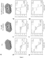
- the core/shell model is demonstrated in Fig. 3 . All surfaces are fully relaxed before exposing them to the reaction intermediates. In each model and in each step of the simulations, the study examined different configurations for the adsorbed species and the most stable ones with the lowest energy are chosen to calculate the reaction energy diagram. Surfaces with vacancy in interaction with adsorbates, in few occasions, are subject to reconstruction. These configurations are avoided in the study's calculations.
- the calculated vacancy formation energy for Cu 2 S/Cu-V is 2.051 eV which is higher than that of the defected pure copper, Cu-V, with 1.3 eV vacancy formation energy.
- reaction pathways for ethanol and ethylene from CO 2 reduction are considered similar until the C 2 H 3 O intermediate. Thereafter, the reaction pathway for ethylene and ethanol splits as mentioned in the following:
- H is the enthalpy
- U is the internal energy
- V is the system volume
- E is the DFT electronic structure energy
- ZPE is the Zero Point Energy arising from the vibrational energy at 0K
- C v is the heat capacity and the relevant integral demonstrates the energy captured by the material from 0K to room temperature in terms of vibration, rotation and translation
- S is the entropy of the system.
- the ZPE, TS and C v terms for the molecular C 2 H 4 , H 2 O and H 2 are adopted from Peterson et al. while the parameters for C 2 H 5 OH are adopted from Calle-Vallejo and Koper.
- the main energy barrier after the adsorbed CH 2 CHO intermediate is the last protonation step to reduce adsorbed OH to water ( ⁇ 0.4 eV).
- the first protonation step of the CH 2 CHO intermediate which reduces it to CH 3 CHO, is the main obstacle ( ⁇ 0.2 eV) after the branch.
- both ethylene and ethanol reaction pathways proceed downhill after the application of 0.5 eV to overcome the earlier dimerization energy barrier.
- Table 1 demonstrates the Gibbs free energies of the reactants and the possible products in their molecular gaseous states.
- Table 1 Cu 2 S Cu -0.9 V vs RHE C 2 H 4 : 29% C 2 H 4 : 34% C 2 H 5 OH: 6% C 2 H 5 OH: 3% -1.0 V vs RHE C 2 H 4 : 45% C 2 H 4 : 50% C 2 H 5 OH: 4% C 2 H 5 OH: 2%
- the computational hydrogen electrode (CHE) that is used to calculate the free energy diagram under different applied potentials, captures energetic differences between elementary steps in proton-coupled-electron-transfer (PCET) processes.
- the chemical potential of the proton-electron pair (H + + e - ) is considered to be equivalent to the chemical potential of a hydrogen molecule (H 2 ) at the reference reversible hydrogen electrode (RHE) potential.
- DFT models cannot determine the chemical potential of a sole proton (H + ) in a bulk electrolyte. Therefore, similar to previous studies on copper, we determined the activation energy barrier for an equivalent hydrogenation reaction.
- the proton-coupled-electron system was considered to be reduced to a surface adsorbed proton via the following equation in: H + + e ⁇ + ⁇ ⁇ H ⁇
- XPS core level binding energy (CLBE) shift calculation The study simulated the XPS CLBE shift ( E CLBEs ) for the Cu 2 S/Cu core/shell model and the Cu 2 S/Cu-V core/shell vacancy model using VASP code.
- n c the total number of core electrons in the system
- E system ( n c - 1) is the total energy of a system with a single core electron removed from the atom of interest
- E system ( n c ) is the total energy of the same system with all core electrons present in the system.
- EXAFS Extended x-ray absorption fine-structure
- the neighbouring atoms to the central atom(s) are divided into j shells, with all atoms with the same atomic number and distance from the central atom grouped into a single shell.
- N j denotes the number of neighbouring atoms in shell j at a distance of R j from the central atom.
- f eff i ( ⁇ , k, R j ) is the ab initio amplitude function for shell j.
- the Debye-Waller term e ⁇ 2 ⁇ j 2 k 2 accounts for damping due to static and thermal disorder in absorber-back scatterer distances.
- the mean free path term e ⁇ 2 R j ⁇ j k reflects losses due to inelastic scattering, where ⁇ j ( k ) is electron mean free path.
- X-ray diffraction patterns were measured on a Philips X'Pert Pro Super X-ray diffractometer equipped with graphite-monochromatized Cu K ⁇ radiation.
- X-ray photoelectron spectroscopy was carried out with the Thermo Scientific K-Alpha XPS system.
- An Al K ⁇ source with a 400 ⁇ m spot size was used for measurements to detect photo-electrons at specific energy ranges to determine the presence of specific elements.
- Sputter depth profiling was performed with an ion gun at 1keV in order to avoid spurious features (e.g. ion beam damage), at a rate of approximately 1 nm/s, where each step has a duration of 20 s.
- TEM Transmission electron microscopy
- HRTEM high-resolution transmission electron microscopy
- HAADF- STEM High-angle annular dark field scanning transmission electron microscopy
- EDS Energy dispersive X-ray spectroscopy
- Elemental mappings and line scans were collected by a Gatan GIF Quantum 965 instrument. Elemental ratio analysis for the samples was measured by an XRF-1800.
- Electrochemical active surface area (ECSA) measurement To determine the ECSA of the electrodes, the study uses two methods to estimate the ECSA. In the first method, cyclic voltammetry (CV) using the ferri-/ferrocyanide redox couple ([Fe(CN) 6 ] 3-/4- ) was employed. The CV was carried out in a nitrogen-purged 5 mM K 3 Fe(CN) 6 /0.1M KCI solution with Ag/AgCI (3M, KCI) and platinum gauze as the reference electrode and counter electrode, respectively.
- CV cyclic voltammetry
- CV was carried out in a nitrogen-purged 5 mM K 3 Fe(CN) 6 /0.1M KCI solution with Ag/AgCI (3M, KCI) and platinum gauze as the reference electrode and counter electrode, respectively.
- the study uses a double layer capacitances method to measure the surface roughness factors for the samples relative to polycrystalline Cu foil.
- the C was determined by measuring the geometric current density at a potential at which no Faradaic process was occurring against the scan rate of cyclic voltammetry (CV). CV was performed in the same electrochemical cell as in the bulk electrolyses with a Nafion proton exchange membrane and 0.1 M KHCO 3 electrolyte. The liner slope gives the C.
- the study used potentiostatic electrochemical impedance spectroscopy (PElS) to determine uncompensated resistance (R u ).
- the resistance values were 80 Ohms for Cu 2 S-V, 78 Ohms for Cu 2 S, and 75 Ohms for Cu in H-cell, and 6.0 Ohms for Cu 2 S-V, 5.5 Ohms for Cu 2 S, and 5.0 Ohms for Cu in Flow-cell configurations respectively.
- the GC running Argon (Linde, 99.999%) as a carrier gas, contained a Molecular Sieve 5A capillary column and a packed Carboxen-1000 column which were used together to separate hydrogen, methane, ethylene and CO 2 .
- a thermal conductivity detector (TCD) was used to quantify hydrogen (H 2 ) and carbon monoxide (CO) and a flame ionization detector (FID) was used to quantify methane (CH 4 ) and ethylene (C 2 H 4 ).
- NMR Nuclear magnetic resonance spectroscopy
- Ex-situ X-ray absorption (XAS) measurement The ex-situ X-ray absorption measurements at the copper L 3 -edge were performed at the spherical grating monochromator (SGM) beamline 11ID-1 at the Canadian Light Source. The scanning energy range of the Cu Ls-edge was between 920 and 960 eV.
- Positron Annihilation Measurement Sandwiched samples composed of catalyst, 22 Na source and catalyst with a total count of 2 million were used for the positron lifetime experiments. A fast-slow coincidence ORTEC system with a time resolution of 270 ps full width at half-maximum was utilized. The ATSUP method was used for calculating positron lifetime. The electron density and the positron crystalline Coulomb potential were built via the non-self-consistent superposition of free atom electron density and Coulomb potential in the absence of the positron.
- Nanoparticles average diameter The morphologies of the nanoparticles are observed by Transmission Electron Microscopy (TEM) images and the diameters are calculated by Image J software.
- TEM Transmission Electron Microscopy
- the present invention evaluated catalyst systems and structures and found that steering post-C-C coupling selectivity can enable high-efficiency electroreduction of carbon dioxide to multi-carbon alcohols.
- the study increased the ratio of alcohol-to-ethylene by over 6 times compared to bare-copper nanoparticles, highlighting a new approach to electro-produce alcohols instead of alkenes.
- the study achieved a C2+ alcohol production rate of 126 mA cm -2 with a selectivity of 32 ⁇ 1% Faradaic efficiency (FE).
- CO 2 carbon dioxide
- CH 4 methane
- C 2 H 4 ethylene
- C1 liquids such as formate (HCOOH).
- liquid multi-carbon alcohols are also highly desired: it stands to enable the synthesis of sustainable fuels that leverage high energy densities (23 KJ/L ethanol, 27 KJ/L propanol) for long-range transportation applications.
- high energy densities 23 KJ/L ethanol, 27 KJ/L propanol
- the production of multi-carbon alcohols via direct CO 2 electroreduction remains below that required for economic viability due to the limited selectivity and low activity of present-day catalysts.
- Copper sulphide structures may be of interest because they may be able to provide a means to form stable surface defects and control the density of surface vacancies. Additionally, copper sulphide derived catalysts can provide long-range modifications of the local density of surface states by introducing sulphur into the Cu structure and affect thereby CO binding.
- DFT studies examine the energetics seen by the adsorbed CH 2 CHO intermediate that may influence alcohol vs ethylene electrosynthesis. These studies point to strategies to switch CO 2 reduction reaction pathways from ethylene to alcohol.
- the studies further included a systematic study of S-enriched Cu and surface vacancies, synthesizing a Cu 2 S/Cu-V (V: vacancy) nanoparticle structure that enables the controllable introduction of vacancies on a copper surface shell with a copper sulphide core.
- This core/shell-vacancy engineering (CSVE) catalyst enabled modifying the C2 reaction pathway, shifting selectivity away from ethylene and toward multi-carbon alcohols.
- Example 2 Theoretical simulations predict selectivity control.
- V-Cu 2 S colloidal vacancy enriched Cu 2 S
- Cuprous sulphide nanoparticles synthesized using the solvothermal method enable controlled copper vacancies in the surface structure of the catalyst.
- the V-Cu 2 S was reduced in a CO 2 saturated electrolyte, yielding a reduced metallic copper shell with enriched vacancies surrounding a Cu 2 S core.
- V-Cu 2 S nanoparticle synthesis Synthesis of the copper (I) sulphide nanocrystals with controlled copper vacancies was performed according to a previously reported method described in Zhuang et al., Chem. Commun., 2012, 48, 9762-9764 with slight modification. In a typical procedure, 130 mg Cu (acac)2 was dissolved by 30 mL dodecanethiol (DDT) in a three-neck flask with magnetic stirring under the protection of nitrogen gas and heated at 240 °C for 20 min. The resulting V-Cu 2 S nanoparticles (V: vacancy) were collected by centrifugation, washed with acetone and hexane three times, and dried within a vacuum chamber.
- DDT dodecanethiol
- the copper (I) sulphide nanoparticles without copper vacancies were prepared using a previously reported method (Wu et al., see below). 1.25 mmol of ammonium diethyldithiocarbamate was mixed with 10 mL of dodecanethiol and 17 mL of oleic acid in a three-neck flask. The solution was heated up to 110 °C under Argon (Ar) flow followed by a quick injection of a suspension composed of 1 mmol of copper(II) acetylacetonate and 3 mL of oleic acid. The solution was then quickly heated up to 180 °C and kept at that temperature for 20 min. The resulting Cu 2 S nanoparticles were collected by centrifugation, washed with acetone and hexane three times and further dried in a vacuum chamber.
- Cu nanoparticles synthesis In a typical synthesis of metallic copper nanoparticles (see Guo, below), 1.2 mmol CuBr and 15 mL oleylamine (OLA) were mixed in a three-neck flask under stirring at 80 °C for 30 min, then 1 mmol trioctylphosphine (TOP) was added and reacted at 80 °C until obtaining a colourless solution. The mixed solution was heated to 260 °C quickly and kept for 1h. The resulting Cu nanoparticles were precipitated by centrifugation, purified with acetone and hexane three times and further dried in a vacuum chamber.
- OVA oleylamine
- TOP trioctylphosphine
- V-Cu 2 S-derived Cu 2 S/Cu-V (CSVE) core/shell nanoparticles Preparation of V-Cu 2 S-derived Cu 2 S/Cu-V (CSVE) core/shell nanoparticles.
- CSVE Cu 2 S/Cu-V core/shell nanoparticles by surface Cu + reduction.
- core/shell nanoparticles can be obtained after initial running (2-5 min).
- the electrolyte was 0.1 M KHCO 3 saturated with CO 2 , which was delivered into the cathodic compartment at a rate of 20.00 standard cubic centimetres per minute (s.c.c.m.).
- the electrolytes KOH solution of various concentrations, 20 mL
- the electrolyte flow was kept at 10 mL min -1 .
- the CO 2 (Linde, 99.99%) flow was kept constant at 50 mL min -1 using a mass flow controller.
- the nanoparticles were analyzed before and after reduction.
- the morphology of the copper sulphide nanoparticles was characterized using transmission electron microscopy (TEM, Figure 2a ), high-resolution TEM (HRTEM, Figure 2b ) and high-angle annular dark-field scanning TEM (HAADF-STEM, Figure 3b and Figure 2c ).
- the nanoparticles have a high degree of uniformity and an average size of 8.5 nm.
- Energy dispersive X-ray spectroscopy (EDS) mapping data ( Figure 3c ) reveal that copper and sulphur are distributed evenly throughout the particle.
- Powder x-ray diffraction (PXRD) analysis ( Figure 2d ) shows good agreement with the standard Cu 1.94 S djurleite phase, thus indicating a non-stoichiometric ratio between copper and sulphur.
- the active nanocatalyst used for CO 2 reduction is then produced from the electrochemical reduction of the V-Cu 2 S nanoparticles which removes sulphur from the surface, thereby constructing Cu 2 S/Cu-V, i.e. a Cu 2 S core with an ultrathin metallic copper shell containing copper vacancies.
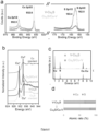
- elemental Cu enriches the nanostructure, while the sulphur signal is decreased but still present, indicating that a fraction of sulphur has been removed during CO 2 reduction ( Figure 3e ).
- XPS X-ray photoelectron spectroscopy
- FIG 4b shows the Cu Ls-edge soft X-ray absorption spectra (sXAS) of the catalyst and corresponding reference standard materials.
- the results show that the V-Cu 2 S exhibits Cu 2 S features before reaction and both Cu 0 and Cu + features after reaction (derived Cu 2 S/Cu-V).
- EDX Energy dispersive X-ray spectroscopy
- Positron annihilation spectroscopy which probes the type and relative concentration of defect vacancies, was carried out to investigate the copper surface.
- the positron lifetime spectra ( Figure 4e ) and the lifetime parameters (see Table 3) show that both the CSVE catalyst and also the Cu 2 S bulk control, exhibit three lifetimes.
- the study assigns the shortest lifetime T 1 (around 260 ps) to the bulk and the longest component ( ⁇ 3 , > 2 ns) to the annihilation of orthopositronium atoms formed in the large voids present in the material.
- the study ascribes the component ⁇ 2 (circa 380 ps) to positron annihilation in trapped Cu vacancies.
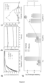
- the electrochemical CO 2 reduction activity and selectivity was first characterized using a three-electrode H-cell system.
- the catalysts were loaded onto a glassy carbon electrode. Linear sweep voltammetry curves were obtained in a CO 2 -saturated 0.1 M KHCO 3 aqueous solution ( Figure 5a ).
- the CSVE catalyst exhibits a total geometric current density of ⁇ 32 mA cm -2 at -0.95 V versus a reversible hydrogen electrode (RHE) during 16 h of continuous electrocatalysis ( Figure 5b ).
- Electrocatalysis was performed using cathodic potentials in the range of -0.85 V to -1.15 V versus RHE ( Figure 5c ). As the applied potential becomes more negative (-0.9 V versus RHE), multi-carbon products are observed, indicating that C-C coupling occurs beyond this potential (see below table 4)
- the study measured the electrochemically active surface area (ECSA) of each catalyst. While the Cu 2 S/Cu-V nanoparticles had a slightly larger ECSA than the Cu 2 S and Cu control nanoparticles, the ECSA difference between the CSVE and control catalysts is less than 4%. The shift in the C2 production pathway and the high current density towards alcohols is therefore ascribed to the catalyst itself rather than to any substantive increase in electrochemically active surface area.
- ECSA electrochemically active surface area
- reaction 2 It was then sought to engineer the reaction environment to work in tandem with the CSVE catalyst to suppress ethylene and boost multi-carbon alcohol production.
- concentration of OH - will be increased proximate to the catalyst surface affecting the bound O* intermediate along the ethylene pathway (Reaction 2), but is expected to leave the ethanol pathway largely unaffected.
- the study turned to a flow-cell configuration that allowed operating in alkaline KOH electrolyte without compromising CO 2 availability.
- the study chose highly alkaline KOH as the electrolyte to increase the pH and electrolyte conductivity, and further enhance CO 2 reduction reaction kinetics by suppressing hydrogen evolution.
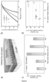
- the configuration bypasses the low CO 2 solubility in KOH via the diffusion of CO 2 across a gas-liquid interface adjacent to the catalyst surface ( Figure 2a ).
- the catalyst was first deposited by spray-coating a nanoparticle ink onto a carbon gas-diffusion electrode (see details below).
- Linear sweep voltammetry curves ( Figure 6b ) of the three catalysts show the lower overpotentials of the CSVE-Cu catalyst at fixed current densities highlighting the improved activity.
- the partial current density exceeded 120 mA cm -2 for multi-carbon alcohols.
Landscapes
- Chemical & Material Sciences (AREA)
- Organic Chemistry (AREA)
- Engineering & Computer Science (AREA)
- Chemical Kinetics & Catalysis (AREA)
- Electrochemistry (AREA)
- Materials Engineering (AREA)
- Metallurgy (AREA)
- General Chemical & Material Sciences (AREA)
- Catalysts (AREA)
- Organic Low-Molecular-Weight Compounds And Preparation Thereof (AREA)
- Inert Electrodes (AREA)
- Electrolytic Production Of Non-Metals, Compounds, Apparatuses Therefor (AREA)
Applications Claiming Priority (2)
| Application Number | Priority Date | Filing Date | Title |
|---|---|---|---|
| US201862670278P | 2018-05-11 | 2018-05-11 | |
| PCT/EP2019/061854 WO2019215247A1 (en) | 2018-05-11 | 2019-05-08 | Core/shell-vacancy engineering (csve) of catalysts for electrochemical co2 reduction |
Publications (2)
| Publication Number | Publication Date |
|---|---|
| EP3791010A1 EP3791010A1 (en) | 2021-03-17 |
| EP3791010B1 true EP3791010B1 (en) | 2023-03-29 |
Family
ID=66589514
Family Applications (1)
| Application Number | Title | Priority Date | Filing Date |
|---|---|---|---|
| EP19724761.2A Active EP3791010B1 (en) | 2018-05-11 | 2019-05-08 | Core/shell-vacancy engineering (csve) of catalysts for electrochemical co2 reduction |
Country Status (8)
| Country | Link |
|---|---|
| US (1) | US11268199B2 (da) |
| EP (1) | EP3791010B1 (da) |
| CA (1) | CA3095972C (da) |
| DK (1) | DK3791010T3 (da) |
| ES (1) | ES2944341T3 (da) |
| FI (1) | FI3791010T3 (da) |
| PT (1) | PT3791010T (da) |
| WO (1) | WO2019215247A1 (da) |
Families Citing this family (11)
| Publication number | Priority date | Publication date | Assignee | Title |
|---|---|---|---|---|
| EP4045699A1 (en) * | 2019-12-12 | 2022-08-24 | Iritaly Trading Company S.r.l. | Electrocatalytic method and apparatus for the simultaneous conversion of methane and coto methanol through an electrochemical reactor operating at ordinary temperatures and pressures, including ambient ones |
| CN112301368B (zh) * | 2020-10-10 | 2022-11-04 | 华东理工大学 | 一种具有疏水性的碳包覆铜微球及其制备方法与应用 |
| CN113136599B (zh) * | 2021-03-13 | 2022-09-16 | 复旦大学 | 一种催化co2还原用电催化剂的离子空位的制造方法 |
| CN113718290B (zh) * | 2021-09-07 | 2022-07-26 | 北京化工大学 | 电催化氧化甘油制甲酸盐用Cu-CuS/BM电极材料及制备方法 |
| CN114277402B (zh) * | 2021-12-15 | 2023-01-06 | 华南理工大学 | 一种共轭导电聚合物改性铜基催化剂及其制备方法与应用 |
| CN115318306B (zh) * | 2022-02-22 | 2023-05-12 | 哈尔滨工业大学 | 一种富Cu2S纳米晶修饰的Cu纳米片及其制备方法和应用 |
| CN115044936B (zh) * | 2022-04-28 | 2023-07-07 | 合肥工业大学 | 一种Pb4S3Br2@CdS核壳结构纳米异质结催化剂、制备方法及其应用 |
| CN115233245B (zh) * | 2022-07-14 | 2025-06-20 | 西北工业大学 | 一种硫化铜-硫化铋异质结纳米片催化剂及制备和应用方法 |
| CN115726001B (zh) * | 2022-11-28 | 2024-03-15 | 中国科学院大连化学物理研究所 | 一种铋铜单原子合金材料及其制备方法与应用 |
| CN116237063B (zh) * | 2023-02-17 | 2023-08-15 | 兰州大学 | 钇促进的二氧化碳还原催化剂及其制备方法 |
| CN116803508B (zh) * | 2023-07-03 | 2025-06-10 | 电子科技大学 | 一种具有表面Cu、S双缺陷位点的光催化剂、制备方法及其应用 |
Family Cites Families (2)
| Publication number | Priority date | Publication date | Assignee | Title |
|---|---|---|---|---|
| US9873115B2 (en) * | 2013-07-01 | 2018-01-23 | The Regents Of The University Of Colorado, A Body Corporate | Nanostructured photocatalysts and doped wide-bandgap semiconductors |
| CN107376851A (zh) * | 2017-08-23 | 2017-11-24 | 三峡大学 | 一种部分硫化金属有机框架复合材料的制备方法及其应用 |
-
2019
- 2019-05-08 CA CA3095972A patent/CA3095972C/en active Active
- 2019-05-08 FI FIEP19724761.2T patent/FI3791010T3/fi active
- 2019-05-08 PT PT197247612T patent/PT3791010T/pt unknown
- 2019-05-08 US US17/052,075 patent/US11268199B2/en active Active
- 2019-05-08 DK DK19724761.2T patent/DK3791010T3/da active
- 2019-05-08 ES ES19724761T patent/ES2944341T3/es active Active
- 2019-05-08 EP EP19724761.2A patent/EP3791010B1/en active Active
- 2019-05-08 WO PCT/EP2019/061854 patent/WO2019215247A1/en not_active Ceased
Also Published As
| Publication number | Publication date |
|---|---|
| DK3791010T3 (da) | 2023-06-06 |
| US20210238759A1 (en) | 2021-08-05 |
| EP3791010A1 (en) | 2021-03-17 |
| ES2944341T3 (es) | 2023-06-20 |
| PT3791010T (pt) | 2023-05-12 |
| WO2019215247A1 (en) | 2019-11-14 |
| CA3095972C (en) | 2023-08-22 |
| CA3095972A1 (en) | 2019-11-14 |
| FI3791010T3 (fi) | 2023-06-09 |
| US11268199B2 (en) | 2022-03-08 |
Similar Documents
| Publication | Publication Date | Title |
|---|---|---|
| EP3791010B1 (en) | Core/shell-vacancy engineering (csve) of catalysts for electrochemical co2 reduction | |
| Pan et al. | Intermediate adsorption states switch to selectively catalyze electrochemical CO2 reduction | |
| Yang et al. | Electrocatalytic CO2 reduction to alcohols by modulating the molecular geometry and Cu coordination in bicentric copper complexes | |
| Peng et al. | Separated growth of Bi-Cu bimetallic electrocatalysts on defective copper foam for highly converting CO2 to formate with alkaline anion-exchange membrane beyond KHCO3 electrolyte | |
| Zhang et al. | Atomic nickel cluster decorated defect-rich copper for enhanced C2 product selectivity in electrocatalytic CO2 reduction | |
| Kim et al. | Identification of single-atom Ni site active toward electrochemical CO2 conversion to CO | |
| Qiu et al. | Boosting electrocatalytic urea production via promoting asymmetric C–N coupling | |
| Liang et al. | Unveiling in situ evolved In/In2O3− x heterostructure as the active phase of In2O3 toward efficient electroreduction of CO2 to formate | |
| EP3670700A1 (en) | Method for converting carbon dioxide (co2) into syngas by an electrolysis reaction | |
| Wang et al. | Multidimensional regulation of Ni3S2@ Co (OH) 2 catalyst with high performance for wind energy electrolytic water | |
| US20160289849A1 (en) | Bifunctional water splitting catalysts and associated methods | |
| US20210292924A1 (en) | Boron-doped copper catalysts for efficient conversion of co2 to multi-carbon hydrocarbons and associated methods | |
| Sun et al. | Ampere-level electroreduction of CO 2 and CO | |
| Chen et al. | Facile synthesis of an antimony-doped Cu/Cu 2 O catalyst with robust CO production in a broad range of potentials for CO 2 electrochemical reduction | |
| Dong et al. | Highly efficient ampere-level CO2 reduction to multicarbon products via stepwise hollow-fiber penetration electrodes | |
| Castagna et al. | Carbon supported PtNiCu nanostructured particles for the electro-oxidation of ethanol in acid environment | |
| Nguyen-Phan et al. | Understanding three-dimensionally interconnected porous oxide-derived copper electrocatalyst for selective carbon dioxide reduction | |
| Wu et al. | Decorated by Cu nanoparticles CoS2 nanoneedle array for effective water oxidation electrocatalysis | |
| Kim et al. | Enhancing ammonia production rates from electrochemical nitrogen reduction by engineering three-phase boundary with phosphorus-activated Cu catalysts | |
| Xu et al. | Compositional gradient Au–Cu bimetallic heterostructures for efficient electroreduction of CO 2 to ethanol at low potential | |
| Tian et al. | Atomic hydrogen pump boosts nitrite-to-ammonia conversion on Cu-Pd catalytic pairs over a wide potential range | |
| Wei et al. | Oxalic acid-assisted vacancy engineering promotes iron–copper sulfide nanosheets for high-current density water oxidation | |
| Zhu et al. | Surface embedded binary Co-Cu hydroxy phosphate over surface of oxy/hydroxides for efficient nitrate reduction to ammonia | |
| Pu et al. | Facile synthesis of indium-doped cuprous oxide catalyst for enhanced electrochemical reduction of CO2 to CO | |
| Xie et al. | Enzyme‐Mimicking Metal–Phosphide Tandem Catalytic Centers for Efficient Electrochemical Nitrate‐to‐Ammonia Conversion and Zinc–Nitrate Battery |
Legal Events
| Date | Code | Title | Description |
|---|---|---|---|
| STAA | Information on the status of an ep patent application or granted ep patent |
Free format text: STATUS: UNKNOWN |
|
| STAA | Information on the status of an ep patent application or granted ep patent |
Free format text: STATUS: THE INTERNATIONAL PUBLICATION HAS BEEN MADE |
|
| PUAI | Public reference made under article 153(3) epc to a published international application that has entered the european phase |
Free format text: ORIGINAL CODE: 0009012 |
|
| STAA | Information on the status of an ep patent application or granted ep patent |
Free format text: STATUS: REQUEST FOR EXAMINATION WAS MADE |
|
| 17P | Request for examination filed |
Effective date: 20201203 |
|
| AK | Designated contracting states |
Kind code of ref document: A1 Designated state(s): AL AT BE BG CH CY CZ DE DK EE ES FI FR GB GR HR HU IE IS IT LI LT LU LV MC MK MT NL NO PL PT RO RS SE SI SK SM TR |
|
| AX | Request for extension of the european patent |
Extension state: BA ME |
|
| DAV | Request for validation of the european patent (deleted) | ||
| DAX | Request for extension of the european patent (deleted) | ||
| STAA | Information on the status of an ep patent application or granted ep patent |
Free format text: STATUS: EXAMINATION IS IN PROGRESS |
|
| 17Q | First examination report despatched |
Effective date: 20220221 |
|
| RAP1 | Party data changed (applicant data changed or rights of an application transferred) |
Owner name: THE GOVERNING COUNCIL OF THE UNIVERSITY OF TORONTO Owner name: TOTALENERGIES ONETECH |
|
| GRAP | Despatch of communication of intention to grant a patent |
Free format text: ORIGINAL CODE: EPIDOSNIGR1 |
|
| STAA | Information on the status of an ep patent application or granted ep patent |
Free format text: STATUS: GRANT OF PATENT IS INTENDED |
|
| RIC1 | Information provided on ipc code assigned before grant |
Ipc: B01J 27/043 20060101ALN20220920BHEP Ipc: H01M 4/90 20060101ALI20220920BHEP Ipc: C25B 3/25 20210101ALI20220920BHEP Ipc: C25B 11/04 20210101AFI20220920BHEP |
|
| INTG | Intention to grant announced |
Effective date: 20221017 |
|
| GRAS | Grant fee paid |
Free format text: ORIGINAL CODE: EPIDOSNIGR3 |
|
| GRAA | (expected) grant |
Free format text: ORIGINAL CODE: 0009210 |
|
| STAA | Information on the status of an ep patent application or granted ep patent |
Free format text: STATUS: THE PATENT HAS BEEN GRANTED |
|
| AK | Designated contracting states |
Kind code of ref document: B1 Designated state(s): AL AT BE BG CH CY CZ DE DK EE ES FI FR GB GR HR HU IE IS IT LI LT LU LV MC MK MT NL NO PL PT RO RS SE SI SK SM TR |
|
| REG | Reference to a national code |
Ref country code: CH Ref legal event code: EP |
|
| REG | Reference to a national code |
Ref country code: DE Ref legal event code: R096 Ref document number: 602019026912 Country of ref document: DE |
|
| REG | Reference to a national code |
Ref country code: AT Ref legal event code: REF Ref document number: 1556713 Country of ref document: AT Kind code of ref document: T Effective date: 20230415 |
|
| REG | Reference to a national code |
Ref country code: IE Ref legal event code: FG4D |
|
| REG | Reference to a national code |
Ref country code: NL Ref legal event code: FP |
|
| REG | Reference to a national code |
Ref country code: PT Ref legal event code: SC4A Ref document number: 3791010 Country of ref document: PT Date of ref document: 20230512 Kind code of ref document: T Free format text: AVAILABILITY OF NATIONAL TRANSLATION Effective date: 20230508 |
|
| REG | Reference to a national code |
Ref country code: DK Ref legal event code: T3 Effective date: 20230530 |
|
| REG | Reference to a national code |
Ref country code: FI Ref legal event code: FGE |
|
| P01 | Opt-out of the competence of the unified patent court (upc) registered |
Effective date: 20230502 |
|
| REG | Reference to a national code |
Ref country code: NO Ref legal event code: T2 Effective date: 20230329 |
|
| REG | Reference to a national code |
Ref country code: ES Ref legal event code: FG2A Ref document number: 2944341 Country of ref document: ES Kind code of ref document: T3 Effective date: 20230620 |
|
| REG | Reference to a national code |
Ref country code: LT Ref legal event code: MG9D |
|
| REG | Reference to a national code |
Ref country code: SE Ref legal event code: TRGR |
|
| PG25 | Lapsed in a contracting state [announced via postgrant information from national office to epo] |
Ref country code: RS Free format text: LAPSE BECAUSE OF FAILURE TO SUBMIT A TRANSLATION OF THE DESCRIPTION OR TO PAY THE FEE WITHIN THE PRESCRIBED TIME-LIMIT Effective date: 20230329 Ref country code: LV Free format text: LAPSE BECAUSE OF FAILURE TO SUBMIT A TRANSLATION OF THE DESCRIPTION OR TO PAY THE FEE WITHIN THE PRESCRIBED TIME-LIMIT Effective date: 20230329 Ref country code: LT Free format text: LAPSE BECAUSE OF FAILURE TO SUBMIT A TRANSLATION OF THE DESCRIPTION OR TO PAY THE FEE WITHIN THE PRESCRIBED TIME-LIMIT Effective date: 20230329 Ref country code: HR Free format text: LAPSE BECAUSE OF FAILURE TO SUBMIT A TRANSLATION OF THE DESCRIPTION OR TO PAY THE FEE WITHIN THE PRESCRIBED TIME-LIMIT Effective date: 20230329 |
|
| PGFP | Annual fee paid to national office [announced via postgrant information from national office to epo] |
Ref country code: DE Payment date: 20230515 Year of fee payment: 5 |
|
| REG | Reference to a national code |
Ref country code: AT Ref legal event code: MK05 Ref document number: 1556713 Country of ref document: AT Kind code of ref document: T Effective date: 20230329 |
|
| PG25 | Lapsed in a contracting state [announced via postgrant information from national office to epo] |
Ref country code: GR Free format text: LAPSE BECAUSE OF FAILURE TO SUBMIT A TRANSLATION OF THE DESCRIPTION OR TO PAY THE FEE WITHIN THE PRESCRIBED TIME-LIMIT Effective date: 20230630 |
|
| PG25 | Lapsed in a contracting state [announced via postgrant information from national office to epo] |
Ref country code: SM Free format text: LAPSE BECAUSE OF FAILURE TO SUBMIT A TRANSLATION OF THE DESCRIPTION OR TO PAY THE FEE WITHIN THE PRESCRIBED TIME-LIMIT Effective date: 20230329 Ref country code: RO Free format text: LAPSE BECAUSE OF FAILURE TO SUBMIT A TRANSLATION OF THE DESCRIPTION OR TO PAY THE FEE WITHIN THE PRESCRIBED TIME-LIMIT Effective date: 20230329 Ref country code: EE Free format text: LAPSE BECAUSE OF FAILURE TO SUBMIT A TRANSLATION OF THE DESCRIPTION OR TO PAY THE FEE WITHIN THE PRESCRIBED TIME-LIMIT Effective date: 20230329 Ref country code: AT Free format text: LAPSE BECAUSE OF FAILURE TO SUBMIT A TRANSLATION OF THE DESCRIPTION OR TO PAY THE FEE WITHIN THE PRESCRIBED TIME-LIMIT Effective date: 20230329 |
|
| PG25 | Lapsed in a contracting state [announced via postgrant information from national office to epo] |
Ref country code: SK Free format text: LAPSE BECAUSE OF FAILURE TO SUBMIT A TRANSLATION OF THE DESCRIPTION OR TO PAY THE FEE WITHIN THE PRESCRIBED TIME-LIMIT Effective date: 20230329 Ref country code: PL Free format text: LAPSE BECAUSE OF FAILURE TO SUBMIT A TRANSLATION OF THE DESCRIPTION OR TO PAY THE FEE WITHIN THE PRESCRIBED TIME-LIMIT Effective date: 20230329 Ref country code: IS Free format text: LAPSE BECAUSE OF FAILURE TO SUBMIT A TRANSLATION OF THE DESCRIPTION OR TO PAY THE FEE WITHIN THE PRESCRIBED TIME-LIMIT Effective date: 20230729 |
|
| REG | Reference to a national code |
Ref country code: CH Ref legal event code: PL |
|
| REG | Reference to a national code |
Ref country code: DE Ref legal event code: R097 Ref document number: 602019026912 Country of ref document: DE |
|
| PG25 | Lapsed in a contracting state [announced via postgrant information from national office to epo] |
Ref country code: MC Free format text: LAPSE BECAUSE OF FAILURE TO SUBMIT A TRANSLATION OF THE DESCRIPTION OR TO PAY THE FEE WITHIN THE PRESCRIBED TIME-LIMIT Effective date: 20230329 |
|
| PG25 | Lapsed in a contracting state [announced via postgrant information from national office to epo] |
Ref country code: MC Free format text: LAPSE BECAUSE OF FAILURE TO SUBMIT A TRANSLATION OF THE DESCRIPTION OR TO PAY THE FEE WITHIN THE PRESCRIBED TIME-LIMIT Effective date: 20230329 Ref country code: LU Free format text: LAPSE BECAUSE OF NON-PAYMENT OF DUE FEES Effective date: 20230508 Ref country code: LI Free format text: LAPSE BECAUSE OF NON-PAYMENT OF DUE FEES Effective date: 20230531 Ref country code: CZ Free format text: LAPSE BECAUSE OF FAILURE TO SUBMIT A TRANSLATION OF THE DESCRIPTION OR TO PAY THE FEE WITHIN THE PRESCRIBED TIME-LIMIT Effective date: 20230329 Ref country code: CH Free format text: LAPSE BECAUSE OF NON-PAYMENT OF DUE FEES Effective date: 20230531 |
|
| PLBE | No opposition filed within time limit |
Free format text: ORIGINAL CODE: 0009261 |
|
| STAA | Information on the status of an ep patent application or granted ep patent |
Free format text: STATUS: NO OPPOSITION FILED WITHIN TIME LIMIT |
|
| REG | Reference to a national code |
Ref country code: IE Ref legal event code: MM4A |
|
| 26N | No opposition filed |
Effective date: 20240103 |
|
| PG25 | Lapsed in a contracting state [announced via postgrant information from national office to epo] |
Ref country code: IE Free format text: LAPSE BECAUSE OF NON-PAYMENT OF DUE FEES Effective date: 20230508 |
|
| PG25 | Lapsed in a contracting state [announced via postgrant information from national office to epo] |
Ref country code: IE Free format text: LAPSE BECAUSE OF NON-PAYMENT OF DUE FEES Effective date: 20230508 |
|
| PG25 | Lapsed in a contracting state [announced via postgrant information from national office to epo] |
Ref country code: SI Free format text: LAPSE BECAUSE OF FAILURE TO SUBMIT A TRANSLATION OF THE DESCRIPTION OR TO PAY THE FEE WITHIN THE PRESCRIBED TIME-LIMIT Effective date: 20230329 |
|
| PG25 | Lapsed in a contracting state [announced via postgrant information from national office to epo] |
Ref country code: SI Free format text: LAPSE BECAUSE OF FAILURE TO SUBMIT A TRANSLATION OF THE DESCRIPTION OR TO PAY THE FEE WITHIN THE PRESCRIBED TIME-LIMIT Effective date: 20230329 Ref country code: IT Free format text: LAPSE BECAUSE OF FAILURE TO SUBMIT A TRANSLATION OF THE DESCRIPTION OR TO PAY THE FEE WITHIN THE PRESCRIBED TIME-LIMIT Effective date: 20230329 |
|
| PG25 | Lapsed in a contracting state [announced via postgrant information from national office to epo] |
Ref country code: BG Free format text: LAPSE BECAUSE OF FAILURE TO SUBMIT A TRANSLATION OF THE DESCRIPTION OR TO PAY THE FEE WITHIN THE PRESCRIBED TIME-LIMIT Effective date: 20230329 |
|
| PG25 | Lapsed in a contracting state [announced via postgrant information from national office to epo] |
Ref country code: BG Free format text: LAPSE BECAUSE OF FAILURE TO SUBMIT A TRANSLATION OF THE DESCRIPTION OR TO PAY THE FEE WITHIN THE PRESCRIBED TIME-LIMIT Effective date: 20230329 |
|
| REG | Reference to a national code |
Ref country code: DE Ref legal event code: R119 Ref document number: 602019026912 Country of ref document: DE |
|
| PG25 | Lapsed in a contracting state [announced via postgrant information from national office to epo] |
Ref country code: DE Free format text: LAPSE BECAUSE OF NON-PAYMENT OF DUE FEES Effective date: 20241203 |
|
| PGFP | Annual fee paid to national office [announced via postgrant information from national office to epo] |
Ref country code: NL Payment date: 20250521 Year of fee payment: 7 |
|
| PGFP | Annual fee paid to national office [announced via postgrant information from national office to epo] |
Ref country code: FI Payment date: 20250526 Year of fee payment: 7 |
|
| PGFP | Annual fee paid to national office [announced via postgrant information from national office to epo] |
Ref country code: GB Payment date: 20250527 Year of fee payment: 7 Ref country code: DK Payment date: 20250526 Year of fee payment: 7 |
|
| PGFP | Annual fee paid to national office [announced via postgrant information from national office to epo] |
Ref country code: NO Payment date: 20250523 Year of fee payment: 7 |
|
| PGFP | Annual fee paid to national office [announced via postgrant information from national office to epo] |
Ref country code: BE Payment date: 20250521 Year of fee payment: 7 |
|
| PGFP | Annual fee paid to national office [announced via postgrant information from national office to epo] |
Ref country code: PT Payment date: 20250429 Year of fee payment: 7 |
|
| PGFP | Annual fee paid to national office [announced via postgrant information from national office to epo] |
Ref country code: FR Payment date: 20250528 Year of fee payment: 7 |
|
| PG25 | Lapsed in a contracting state [announced via postgrant information from national office to epo] |
Ref country code: CY Free format text: LAPSE BECAUSE OF FAILURE TO SUBMIT A TRANSLATION OF THE DESCRIPTION OR TO PAY THE FEE WITHIN THE PRESCRIBED TIME-LIMIT; INVALID AB INITIO Effective date: 20190508 |
|
| PGFP | Annual fee paid to national office [announced via postgrant information from national office to epo] |
Ref country code: SE Payment date: 20250521 Year of fee payment: 7 |
|
| PG25 | Lapsed in a contracting state [announced via postgrant information from national office to epo] |
Ref country code: HU Free format text: LAPSE BECAUSE OF FAILURE TO SUBMIT A TRANSLATION OF THE DESCRIPTION OR TO PAY THE FEE WITHIN THE PRESCRIBED TIME-LIMIT; INVALID AB INITIO Effective date: 20190508 |
|
| PGFP | Annual fee paid to national office [announced via postgrant information from national office to epo] |
Ref country code: ES Payment date: 20250630 Year of fee payment: 7 |
|
| PG25 | Lapsed in a contracting state [announced via postgrant information from national office to epo] |
Ref country code: TR Free format text: LAPSE BECAUSE OF FAILURE TO SUBMIT A TRANSLATION OF THE DESCRIPTION OR TO PAY THE FEE WITHIN THE PRESCRIBED TIME-LIMIT Effective date: 20230329 |