EP3791114B1 - Système de chauffage et/ou de production d'eau chaude sanitaire - Google Patents
Système de chauffage et/ou de production d'eau chaude sanitaire Download PDFInfo
- Publication number
- EP3791114B1 EP3791114B1 EP19723090.7A EP19723090A EP3791114B1 EP 3791114 B1 EP3791114 B1 EP 3791114B1 EP 19723090 A EP19723090 A EP 19723090A EP 3791114 B1 EP3791114 B1 EP 3791114B1
- Authority
- EP
- European Patent Office
- Prior art keywords
- hot water
- heating
- heat exchanger
- heat
- circuit
- Prior art date
- Legal status (The legal status is an assumption and is not a legal conclusion. Google has not performed a legal analysis and makes no representation as to the accuracy of the status listed.)
- Active
Links
Images


Classifications
-
- F—MECHANICAL ENGINEERING; LIGHTING; HEATING; WEAPONS; BLASTING
- F24—HEATING; RANGES; VENTILATING
- F24D—DOMESTIC- OR SPACE-HEATING SYSTEMS, e.g. CENTRAL HEATING SYSTEMS; DOMESTIC HOT-WATER SUPPLY SYSTEMS; ELEMENTS OR COMPONENTS THEREFOR
- F24D3/00—Hot-water central heating systems
- F24D3/18—Hot-water central heating systems using heat pumps
-
- F—MECHANICAL ENGINEERING; LIGHTING; HEATING; WEAPONS; BLASTING
- F24—HEATING; RANGES; VENTILATING
- F24D—DOMESTIC- OR SPACE-HEATING SYSTEMS, e.g. CENTRAL HEATING SYSTEMS; DOMESTIC HOT-WATER SUPPLY SYSTEMS; ELEMENTS OR COMPONENTS THEREFOR
- F24D17/00—Domestic hot-water supply systems
- F24D17/02—Domestic hot-water supply systems using heat pumps
-
- F—MECHANICAL ENGINEERING; LIGHTING; HEATING; WEAPONS; BLASTING
- F24—HEATING; RANGES; VENTILATING
- F24D—DOMESTIC- OR SPACE-HEATING SYSTEMS, e.g. CENTRAL HEATING SYSTEMS; DOMESTIC HOT-WATER SUPPLY SYSTEMS; ELEMENTS OR COMPONENTS THEREFOR
- F24D19/00—Details
- F24D19/10—Arrangement or mounting of control or safety devices
- F24D19/1006—Arrangement or mounting of control or safety devices for water heating systems
- F24D19/1066—Arrangement or mounting of control or safety devices for water heating systems for the combination of central heating and domestic hot water
- F24D19/1069—Arrangement or mounting of control or safety devices for water heating systems for the combination of central heating and domestic hot water regulation in function of the temperature of the domestic hot water
-
- F—MECHANICAL ENGINEERING; LIGHTING; HEATING; WEAPONS; BLASTING
- F24—HEATING; RANGES; VENTILATING
- F24D—DOMESTIC- OR SPACE-HEATING SYSTEMS, e.g. CENTRAL HEATING SYSTEMS; DOMESTIC HOT-WATER SUPPLY SYSTEMS; ELEMENTS OR COMPONENTS THEREFOR
- F24D19/00—Details
- F24D19/10—Arrangement or mounting of control or safety devices
- F24D19/1006—Arrangement or mounting of control or safety devices for water heating systems
- F24D19/1066—Arrangement or mounting of control or safety devices for water heating systems for the combination of central heating and domestic hot water
- F24D19/1072—Arrangement or mounting of control or safety devices for water heating systems for the combination of central heating and domestic hot water the system uses a heat pump
-
- F—MECHANICAL ENGINEERING; LIGHTING; HEATING; WEAPONS; BLASTING
- F25—REFRIGERATION OR COOLING; COMBINED HEATING AND REFRIGERATION SYSTEMS; HEAT PUMP SYSTEMS; MANUFACTURE OR STORAGE OF ICE; LIQUEFACTION SOLIDIFICATION OF GASES
- F25B—REFRIGERATION MACHINES, PLANTS OR SYSTEMS; COMBINED HEATING AND REFRIGERATION SYSTEMS; HEAT PUMP SYSTEMS
- F25B29/00—Combined heating and refrigeration systems, e.g. operating alternately or simultaneously
- F25B29/003—Combined heating and refrigeration systems, e.g. operating alternately or simultaneously of the compression type system
-
- F—MECHANICAL ENGINEERING; LIGHTING; HEATING; WEAPONS; BLASTING
- F25—REFRIGERATION OR COOLING; COMBINED HEATING AND REFRIGERATION SYSTEMS; HEAT PUMP SYSTEMS; MANUFACTURE OR STORAGE OF ICE; LIQUEFACTION SOLIDIFICATION OF GASES
- F25B—REFRIGERATION MACHINES, PLANTS OR SYSTEMS; COMBINED HEATING AND REFRIGERATION SYSTEMS; HEAT PUMP SYSTEMS
- F25B47/00—Arrangements for preventing or removing deposits or corrosion, not provided for in another subclass
- F25B47/02—Defrosting cycles
- F25B47/022—Defrosting cycles hot gas defrosting
-
- F—MECHANICAL ENGINEERING; LIGHTING; HEATING; WEAPONS; BLASTING
- F25—REFRIGERATION OR COOLING; COMBINED HEATING AND REFRIGERATION SYSTEMS; HEAT PUMP SYSTEMS; MANUFACTURE OR STORAGE OF ICE; LIQUEFACTION SOLIDIFICATION OF GASES
- F25B—REFRIGERATION MACHINES, PLANTS OR SYSTEMS; COMBINED HEATING AND REFRIGERATION SYSTEMS; HEAT PUMP SYSTEMS
- F25B5/00—Compression machines, plants or systems, with several evaporator circuits, e.g. for varying refrigerating capacity
- F25B5/04—Compression machines, plants or systems, with several evaporator circuits, e.g. for varying refrigerating capacity arranged in series
-
- F—MECHANICAL ENGINEERING; LIGHTING; HEATING; WEAPONS; BLASTING
- F24—HEATING; RANGES; VENTILATING
- F24D—DOMESTIC- OR SPACE-HEATING SYSTEMS, e.g. CENTRAL HEATING SYSTEMS; DOMESTIC HOT-WATER SUPPLY SYSTEMS; ELEMENTS OR COMPONENTS THEREFOR
- F24D2200/00—Heat sources or energy sources
- F24D2200/08—Electric heater
-
- F—MECHANICAL ENGINEERING; LIGHTING; HEATING; WEAPONS; BLASTING
- F24—HEATING; RANGES; VENTILATING
- F24D—DOMESTIC- OR SPACE-HEATING SYSTEMS, e.g. CENTRAL HEATING SYSTEMS; DOMESTIC HOT-WATER SUPPLY SYSTEMS; ELEMENTS OR COMPONENTS THEREFOR
- F24D2200/00—Heat sources or energy sources
- F24D2200/12—Heat pump
-
- F—MECHANICAL ENGINEERING; LIGHTING; HEATING; WEAPONS; BLASTING
- F24—HEATING; RANGES; VENTILATING
- F24D—DOMESTIC- OR SPACE-HEATING SYSTEMS, e.g. CENTRAL HEATING SYSTEMS; DOMESTIC HOT-WATER SUPPLY SYSTEMS; ELEMENTS OR COMPONENTS THEREFOR
- F24D2200/00—Heat sources or energy sources
- F24D2200/16—Waste heat
- F24D2200/29—Electrical devices, e.g. computers, servers
-
- F—MECHANICAL ENGINEERING; LIGHTING; HEATING; WEAPONS; BLASTING
- F24—HEATING; RANGES; VENTILATING
- F24D—DOMESTIC- OR SPACE-HEATING SYSTEMS, e.g. CENTRAL HEATING SYSTEMS; DOMESTIC HOT-WATER SUPPLY SYSTEMS; ELEMENTS OR COMPONENTS THEREFOR
- F24D2220/00—Components of central heating installations excluding heat sources
- F24D2220/07—Heat pipes
-
- F—MECHANICAL ENGINEERING; LIGHTING; HEATING; WEAPONS; BLASTING
- F24—HEATING; RANGES; VENTILATING
- F24F—AIR-CONDITIONING; AIR-HUMIDIFICATION; VENTILATION; USE OF AIR CURRENTS FOR SCREENING
- F24F5/00—Air-conditioning systems or apparatus not covered by F24F1/00 or F24F3/00, e.g. using solar heat or combined with household units such as an oven or water heater
- F24F5/0096—Air-conditioning systems or apparatus not covered by F24F1/00 or F24F3/00, e.g. using solar heat or combined with household units such as an oven or water heater combined with domestic apparatus
-
- F—MECHANICAL ENGINEERING; LIGHTING; HEATING; WEAPONS; BLASTING
- F25—REFRIGERATION OR COOLING; COMBINED HEATING AND REFRIGERATION SYSTEMS; HEAT PUMP SYSTEMS; MANUFACTURE OR STORAGE OF ICE; LIQUEFACTION SOLIDIFICATION OF GASES
- F25B—REFRIGERATION MACHINES, PLANTS OR SYSTEMS; COMBINED HEATING AND REFRIGERATION SYSTEMS; HEAT PUMP SYSTEMS
- F25B2313/00—Compression machines, plants or systems with reversible cycle not otherwise provided for
- F25B2313/027—Compression machines, plants or systems with reversible cycle not otherwise provided for characterised by the reversing means
- F25B2313/02741—Compression machines, plants or systems with reversible cycle not otherwise provided for characterised by the reversing means using one four-way valve
-
- F—MECHANICAL ENGINEERING; LIGHTING; HEATING; WEAPONS; BLASTING
- F25—REFRIGERATION OR COOLING; COMBINED HEATING AND REFRIGERATION SYSTEMS; HEAT PUMP SYSTEMS; MANUFACTURE OR STORAGE OF ICE; LIQUEFACTION SOLIDIFICATION OF GASES
- F25B—REFRIGERATION MACHINES, PLANTS OR SYSTEMS; COMBINED HEATING AND REFRIGERATION SYSTEMS; HEAT PUMP SYSTEMS
- F25B2339/00—Details of evaporators; Details of condensers
- F25B2339/04—Details of condensers
- F25B2339/047—Water-cooled condensers
-
- Y—GENERAL TAGGING OF NEW TECHNOLOGICAL DEVELOPMENTS; GENERAL TAGGING OF CROSS-SECTIONAL TECHNOLOGIES SPANNING OVER SEVERAL SECTIONS OF THE IPC; TECHNICAL SUBJECTS COVERED BY FORMER USPC CROSS-REFERENCE ART COLLECTIONS [XRACs] AND DIGESTS
- Y02—TECHNOLOGIES OR APPLICATIONS FOR MITIGATION OR ADAPTATION AGAINST CLIMATE CHANGE
- Y02B—CLIMATE CHANGE MITIGATION TECHNOLOGIES RELATED TO BUILDINGS, e.g. HOUSING, HOUSE APPLIANCES OR RELATED END-USER APPLICATIONS
- Y02B10/00—Integration of renewable energy sources in buildings
- Y02B10/70—Hybrid systems, e.g. uninterruptible or back-up power supplies integrating renewable energies
-
- Y—GENERAL TAGGING OF NEW TECHNOLOGICAL DEVELOPMENTS; GENERAL TAGGING OF CROSS-SECTIONAL TECHNOLOGIES SPANNING OVER SEVERAL SECTIONS OF THE IPC; TECHNICAL SUBJECTS COVERED BY FORMER USPC CROSS-REFERENCE ART COLLECTIONS [XRACs] AND DIGESTS
- Y02—TECHNOLOGIES OR APPLICATIONS FOR MITIGATION OR ADAPTATION AGAINST CLIMATE CHANGE
- Y02B—CLIMATE CHANGE MITIGATION TECHNOLOGIES RELATED TO BUILDINGS, e.g. HOUSING, HOUSE APPLIANCES OR RELATED END-USER APPLICATIONS
- Y02B30/00—Energy efficient heating, ventilation or air conditioning [HVAC]
- Y02B30/12—Hot water central heating systems using heat pumps
-
- Y—GENERAL TAGGING OF NEW TECHNOLOGICAL DEVELOPMENTS; GENERAL TAGGING OF CROSS-SECTIONAL TECHNOLOGIES SPANNING OVER SEVERAL SECTIONS OF THE IPC; TECHNICAL SUBJECTS COVERED BY FORMER USPC CROSS-REFERENCE ART COLLECTIONS [XRACs] AND DIGESTS
- Y02—TECHNOLOGIES OR APPLICATIONS FOR MITIGATION OR ADAPTATION AGAINST CLIMATE CHANGE
- Y02B—CLIMATE CHANGE MITIGATION TECHNOLOGIES RELATED TO BUILDINGS, e.g. HOUSING, HOUSE APPLIANCES OR RELATED END-USER APPLICATIONS
- Y02B30/00—Energy efficient heating, ventilation or air conditioning [HVAC]
- Y02B30/52—Heat recovery pumps, i.e. heat pump based systems or units able to transfer the thermal energy from one area of the premises or part of the facilities to a different one, improving the overall efficiency
Definitions
- the present invention relates to a heating and/or hot water preparation system which is designed to produce heating water and/or hot water.
- heaters include heat pumps, for example, but direct heating systems are also conceivable.
- Using the same heater or heat generator for hot water and heating water production is possible, but in this case, hot water and heating energy are provided alternatively. This means that while hot water is being generated, the heating water is not being heated, and the rooms heated by the heater are at risk of cooling down.
- the difficulty of heating domestic hot water and heating water in parallel is primarily due to the fact that the heating water and the domestic hot water are provided at different temperatures.
- a typical flow temperature for heating water for example, is in the range of 50 to 60°C, although modern passive houses in particular allow for significantly lower heating flow temperatures.
- the desired temperature for domestic hot water can be significantly higher.
- WO 2007/004962 A1 discloses a heating system comprising a heat pump for simultaneously or separately heating a hot water circuit and a heating circuit.
- An adjustable switching valve is arranged in a section of a heating circuit, by means of which partial quantities of the medium are directed toward the heating circuit and/or the hot water circuit.
- US 4,955,207 A1 discloses a combined hot water heater-cooling assembly with a cooling assembly coupled to a hot water tank via a heat pipe.
- the heat-emitting end of the heat pipe is located near the bottom of the hot water tank.
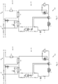
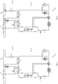
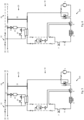
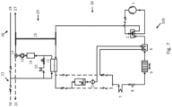
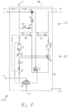
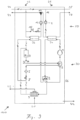
- a heating and/or hot water preparation system comprising a heating circuit and a heat pump circuit, wherein the heat pump circuit has a heat exchanger device configured to transfer heat from the heat pump circuit to the heating circuit.
- the heating circuit comprises a heating circuit with a heating flow and a heating post-flow, a hot water circuit with a hot water flow and a hot water post-flow, and a controllable mixer, wherein the mixer is configured to divide a volume flow through the heating circuit at least between the heating flow and the hot water flow.
- the heat exchanger device has a first heat exchanger and, in series therewith, a second heat exchanger. The second heat exchanger is configured to transfer heat to the heating circuit upstream of the mixer, and the first heat exchanger is configured to transfer heat to the hot water flow downstream of the mixer.
- the heat exchanger device has two heat exchangers connected in series, the hot water flow can be heated to a higher temperature, than the heating circuit, which will be explained further below.
- the heat exchangers are connected in series in the direction of refrigerant flow, i.e., on the heat pump circuit side, but not necessarily on the heating circuit side. This allows the hot water circuit to generate hot water at a higher temperature than required for the heating flow. This ensures energy-optimized operation of the heating and/or hot water system.
- in series specifically means that the same refrigerant flows through the first heat exchanger and the second heat exchanger at consecutive times. It is irrelevant whether other components of the heat pump circuit are located between the first heat exchanger and the second heat exchanger in the direction of refrigerant flow, as long as the sequential, i.e., non-parallel, flow through the first and second heat exchangers is maintained. In other words, the "in series” arrangement can be distinguished from a parallel connection of the first heat exchanger and the second heat exchanger.
- the adjustable mixer allows for simultaneous operation of the heating system and the provision of hot water. Compared to diverter valves of conventional solutions, this prevents unwanted drops in room temperatures when hot water is being provided.
- the clever control of the mixer makes it possible to optimally distribute the heating output provided by the heat pump circuit between the hot water generation and the heating circuit.
- a suitable refrigerant preferably flows through the heat pump circuit. All types of heat pumps, such as air or brine heat pumps, can be advantageously used.
- the first heat exchanger is designed as a desuperheater
- the second heat exchanger is designed as a condenser. Accordingly, the gaseous refrigerant flowing through the heat pump circuit through the heat exchanger device is cooled in the first heat exchanger without, however, significantly condensing, while the phase transition to the liquid phase essentially takes place in the second heat exchanger.
- the temperature of the refrigerant in the desuperheater can be reduced from 90°C (30°C-150°C) to 57°C (20°C-150°C), while the refrigerant in the condenser arranged in series is then cooled from 57°C (20°C-150°C) to 49°C (15°C-80°C). and is liquefied in the process.
- the values in parentheses indicate the temperature ranges typically expected at the relevant positions, depending on the selected refrigerant.
- the water in the heating circuit can be heated from, for example, 47°C (10°C-80°C) by the condenser to, for example, 55°C (15°C-85°C), thus reaching the desired flow temperature. Downstream of the mixer, the hot water flow can then be further heated to, for example, 75°C (15°C-95°C).
- the numerical values are examples to illustrate the operating principle of the invention.
- the desuperheater is designed as a heat pipe, thermosiphon and/or heat pipe between the heat pump circuit and the hot water circuit.
- thermosiphon, and/or heat pipe design is that heat transfer only occurs as long as the temperature level in the hot water circuit does not exceed a certain value, which is determined, for example, by the temperature of the refrigerant in the desuperheater and the desuperheater design.
- the desuperheater is essentially self-limiting. This prevents boiling and potential damage to the entire system, even when no fluid is flowing in the hot water circuit.
- the desuperheater is designed as a heat pipe.
- the circulation of a refrigerant in the heat pipe occurs due to gravity and not, for example, due to capillary effects as in a heat pipe.
- the design of the heat transfer through the heat pipe can thus be influenced by the installation position.
- the pressure loss across the first heat exchanger differs from the pressure loss across the second heat exchanger. Pressure losses are associated with performance losses and are therefore rather undesirable. However, heat exchangers with high pressure losses, such as plate heat exchangers, are particularly advantageous for the condenser due to their high heat transfer performance. From an efficiency perspective, it has proven particularly advantageous to configure the first heat exchanger with a lower pressure loss than the second heat exchanger.
- the hot water circuit is arranged to heat a hot water storage tank to a desired temperature
- the mixer is designed to regulate the volume flow, in particular through the hot water circuit, such that the temperature in the hot water storage tank follows the desired value
- a circulation pump is arranged in the heating circuit.
- the circulation pump ensures that the heating circuit fluid, in particular water, flows through the heating circuit, i.e., the heating circuit and/or the hot water circuit.
Landscapes
- Engineering & Computer Science (AREA)
- Physics & Mathematics (AREA)
- Mechanical Engineering (AREA)
- Thermal Sciences (AREA)
- General Engineering & Computer Science (AREA)
- Chemical & Material Sciences (AREA)
- Combustion & Propulsion (AREA)
- Heat-Pump Type And Storage Water Heaters (AREA)
- Steam Or Hot-Water Central Heating Systems (AREA)
Claims (10)
- Système de préparation d'eau chaude et/ou de chauffage (100) comprenant :un circuit de chauffe (20) et un circuit de pompe à chaleur (30), le circuit de pompe à chaleur (30) présentant un dispositif de transfert de chaleur (3) qui est conçu pour transférer de la chaleur du circuit de pompe à chaleur (30) au circuit de chauffe (20),le circuit de chauffe (20) comprenant un circuit de chauffage (22) doté d'un départ chauffage (23) et d'un retour chauffage (24), un circuit d'eau chaude (26) doté d'un départ eau chaude (27) et d'un retour eau chaude (28) et un mélangeur (13) régulable, le mélangeur (13) étant conçu pour répartir un débit volumique dans le circuit de chauffe (20) au moins entre le départ chauffage (23) et le départ eau chaude (27),le dispositif de transfert de chaleur (3) présentant un premier échangeur de chaleur (3a) et, monté en série avec celui-ci, un second échangeur de chaleur (3b),le second échangeur de chaleur (3b) étant conçu pour transférer de la chaleur au circuit de chauffe (20) en amont du mélangeur (13) etle premier échangeur de chaleur (3a) étant conçu pour transférer de la chaleur au départ eau chaude (27) en aval du mélangeur (13),le premier échangeur de chaleur (3a) étant réalisé sous la forme d'un désurchauffeur et le second échangeur de chaleur (3b) sous la forme d'un condenseur,caractérisé en ce que le désurchauffeur est réalisé sous la forme d'un tube échangeur de chaleur, d'un thermosiphon et/ou d'un caloduc (15) entre le circuit de pompe à chaleur (30) et le circuit d'eau chaude (26) et le condenseur sous la forme d'un échangeur de chaleur à plaques, la perte de charge dans le premier échangeur de chaleur (3a) étant inférieure à la perte de charge dans le second échangeur de chaleur (3b).
- Système de préparation d'eau chaude et/ou de chauffage (100) selon la revendication 1, dans lequel le circuit d'eau chaude (26) est agencé de façon à chauffer un ballon d'eau chaude à une température souhaitée, le mélangeur (13) étant conçu pour réguler le débit volumique en particulier dans le circuit d'eau chaude (26) de telle manière que la température du ballon d'eau chaude suit la valeur souhaitée.
- Système de préparation d'eau chaude et/ou de chauffage (100) selon la revendication 1 ou 2, dans lequel un circulateur (12) est agencé dans le circuit de chauffe (20).
- Système de préparation d'eau chaude et/ou de chauffage (100) selon l'une quelconque des revendications précédentes, dans lequel un chauffage direct (14) est agencé dans le départ eau chaude (27) en aval du premier échangeur de chaleur (3a).
- Système de préparation d'eau chaude et/ou de chauffage (100) selon l'une quelconque des revendications précédentes, dans lequel il est agencé une conduite de dérivation destinée à faire passer à côté du premier échangeur de chaleur (3a) un fluide frigorigène circulant dans le circuit de pompe à chaleur (30).
- Système de préparation d'eau chaude et/ou de chauffage (100) selon l'une quelconque des revendications précédentes, le système de préparation d'eau chaude et/ou de chauffage (100) pouvant être exploité purement en mode chauffage, purement en mode eau chaude ou en mode parallèle chauffage et eau chaude.
- Système de préparation d'eau chaude et/ou de chauffage (100) selon l'une quelconque des revendications précédentes, dans lequel, en mode chauffage, un débit volumique minimum circulant dans le circuit d'eau chaude est maintenu, le débit volumique minimum étant dimensionné de manière à empêcher une ébullition dans le circuit d'eau chaude.
- Système de préparation d'eau chaude et/ou de chauffage (100) selon l'une quelconque des revendications précédentes, dans lequel le circuit de pompe à chaleur (30) présente une vanne d'inversion (2), la vanne d'inversion (2) étant agencée de telle manière que, lors de la commutation de la vanne d'inversion (2), le sens d'écoulement d'un fluide frigorigène s'écoulant dans le circuit de pompe à chaleur (30) reste identique dans le premier échangeur de chaleur (3a) et s'inverse dans le second échangeur de chaleur (3b).
- Système de préparation d'eau chaude et/ou de chauffage (100) selon la revendication 8, dans lequel le premier échangeur de chaleur (3a) et le second échangeur de chaleur (3b) sont agencés dans le circuit de pompe à chaleur (30) sur différents côtés de la vanne d'inversion (2).
- Procédé de régulation d'un système de préparation d'eau chaude et/ou de chauffage selon l'une quelconque des revendications précédentes, le procédé comprenant le réglage de la position d'un mélangeur (13) entre le circuit de chauffage (22) et le circuit d'eau chaude (26) d'un circuit de chauffe (20) en fonction de la température d'un ballon d'eau chaude.
Applications Claiming Priority (2)
| Application Number | Priority Date | Filing Date | Title |
|---|---|---|---|
| DE102018111056.1A DE102018111056A1 (de) | 2018-05-08 | 2018-05-08 | Heizungs- und/oder Warmwasserbereitungssystem |
| PCT/EP2019/061834 WO2019215240A1 (fr) | 2018-05-08 | 2019-05-08 | Système de chauffage et/ou de production d'eau chaude sanitaire |
Publications (2)
| Publication Number | Publication Date |
|---|---|
| EP3791114A1 EP3791114A1 (fr) | 2021-03-17 |
| EP3791114B1 true EP3791114B1 (fr) | 2025-03-12 |
Family
ID=66476642
Family Applications (1)
| Application Number | Title | Priority Date | Filing Date |
|---|---|---|---|
| EP19723090.7A Active EP3791114B1 (fr) | 2018-05-08 | 2019-05-08 | Système de chauffage et/ou de production d'eau chaude sanitaire |
Country Status (3)
| Country | Link |
|---|---|
| EP (1) | EP3791114B1 (fr) |
| DE (1) | DE102018111056A1 (fr) |
| WO (1) | WO2019215240A1 (fr) |
Families Citing this family (5)
| Publication number | Priority date | Publication date | Assignee | Title |
|---|---|---|---|---|
| CN113375209B (zh) * | 2021-06-28 | 2022-03-01 | 大唐环境产业集团股份有限公司 | 燃煤机组耦合压缩式热泵的大温差供热方法及系统 |
| DE102022121699A1 (de) | 2022-08-26 | 2024-02-29 | Konvekta Aktiengesellschaft | Wärmepumpenanlage mit mehrstufiger Wärmeübertragung und Verfahren dazu |
| EP4354026A1 (fr) * | 2022-10-11 | 2024-04-17 | BDR Thermea Group B.V. | Système de pompe à chaleur et procédé de fonctionnement d'un système de pompe à chaleur |
| DE102023118698A1 (de) * | 2023-07-14 | 2025-01-16 | Mahle International Gmbh | Modul und Baugruppe für ein stationäres Wärmepumpensystem |
| DE102023122220A1 (de) | 2023-08-18 | 2025-03-06 | Konvekta Aktiengesellschaft | Heizungs- und Warmwasserbereitungssystem sowie Verfahren dafür |
Family Cites Families (7)
| Publication number | Priority date | Publication date | Assignee | Title |
|---|---|---|---|---|
| DE2711144A1 (de) * | 1977-03-15 | 1978-09-28 | Hannover Braunschweigische Str | Verfahren zum betrieb einer waermepumpe |
| US4955207A (en) * | 1989-09-26 | 1990-09-11 | Mink Clark B | Combination hot water heater-refrigeration assembly |
| BE1015448A6 (nl) * | 2003-03-27 | 2005-04-05 | Simon Luc | Lucht water warmtepomp. |
| JP4700690B2 (ja) * | 2005-06-30 | 2011-06-15 | 東芝キヤリア株式会社 | ヒートポンプ式給湯装置 |
| SE530407C2 (sv) * | 2005-07-06 | 2008-05-27 | Thermia Vaerme Ab | Regleranordning |
| CN102753914B (zh) * | 2010-02-26 | 2014-07-23 | 株式会社日立制作所 | 空气调节装置和空气调节热水供给系统 |
| DE102013001455A1 (de) * | 2013-01-28 | 2014-08-14 | Hochschule für angewandte Wissenschaften München | Anordnung und Verfahren zur Wärmeversorgung eines Gebäudes |
-
2018
- 2018-05-08 DE DE102018111056.1A patent/DE102018111056A1/de not_active Ceased
-
2019
- 2019-05-08 EP EP19723090.7A patent/EP3791114B1/fr active Active
- 2019-05-08 WO PCT/EP2019/061834 patent/WO2019215240A1/fr not_active Ceased
Also Published As
| Publication number | Publication date |
|---|---|
| WO2019215240A1 (fr) | 2019-11-14 |
| DE102018111056A1 (de) | 2019-11-14 |
| EP3791114A1 (fr) | 2021-03-17 |
Similar Documents
| Publication | Publication Date | Title |
|---|---|---|
| EP3791114A1 (fr) | Système de chauffage et/ou de production d'eau chaude sanitaire | |
| DE102014014923B4 (de) | Wärmepumpen-System für ein Fahrzeug | |
| EP3648997B1 (fr) | Installation frigorifique pour véhicule pourvue d'un circuit de réfrigération équipé d'un échangeur thermique et échangeur thermique conçu pour une telle installation frigorifique | |
| DE102010051976B4 (de) | Klimaanlage für ein Kraftfahrzeug | |
| EP0096822B1 (fr) | Procédé pour le fonctionnement d'une pompe à chaleur à absorption bivalente et pompe à chaleur à absorption pour la réalisation de ce procédé | |
| EP3595919B1 (fr) | Installation frigorifique d'un véhicule avec un circuit de réfrigérant pouvant fonctionner comme un circuit frigorifique pour un mode ac et comme circuit de pompe à chaleur pour un mode de chauffage | |
| WO2009146856A1 (fr) | Installation de climatisation pour le conditionnement de plusieurs fluides | |
| EP2119985A2 (fr) | Dispositif de régulation de la température à base d'une pompe à chaleur | |
| WO2009024282A2 (fr) | Dispositif d'équilibrage de température à base de pompe à chaleur | |
| DE102021127770A1 (de) | Thermomanagementsystem für ein Kraftfahrzeug und Kraftfahrzeug mit einem solchen | |
| EP2848870B1 (fr) | Installation de chauffage et procédé destiné au fonctionnement d'une installation de chauffage | |
| EP3417213A1 (fr) | Appareil de froid pourvu d'une pluralité de compartiments de stockage | |
| EP3699515A1 (fr) | Chambre de mise en température et procédé | |
| WO2023061685A1 (fr) | Système de gestion thermique pour véhicule automobile | |
| DE102009004501B4 (de) | Wärmepumpe und Verfahren zur Regelung der Quelleneingangstemperatur an der Wärmepumpe | |
| DE3301303A1 (de) | Klimaanlage | |
| DE102013005035A1 (de) | Verfahren und Vorrichtung zur Einkopplung von Wärme aus einem Nahwärmenetz | |
| EP1266779B1 (fr) | Circuit de refroidissement de véhicule pour le refroidissement d'un dispositif d'augmentation de la température avec un réfrigérant | |
| WO2021094054A1 (fr) | Procédé pour la gestion thermique d'un véhicule à moteur | |
| EP3417212A1 (fr) | Appareil de froid pourvu d'une pluralité de compartiments de stockage | |
| DE102018215026A1 (de) | Kälteanlage für ein Fahrzeug mit einem einen zweiflutigen Wärmeübertrager aufweisenden Kältemittelkreislauf sowie Wärmeübertrager und Verfahren zum Betreiben der Kälteanlage | |
| EP2458304A2 (fr) | Installation de pompe à chaleur comprenant une pompe à chaleur et procédé de fonctionnement d'une telle installation de pompe à chaleur | |
| EP1394482B1 (fr) | Installation de pompe à chaleur | |
| DE102019001642A1 (de) | Heizungs-und/oder Warmwasserbereitungssystem | |
| EP3980695B1 (fr) | Procédé pour faire fonctionner une installation de chauffage comprenant une pompe de chaleur et installation de chauffage |
Legal Events
| Date | Code | Title | Description |
|---|---|---|---|
| STAA | Information on the status of an ep patent application or granted ep patent |
Free format text: STATUS: UNKNOWN |
|
| STAA | Information on the status of an ep patent application or granted ep patent |
Free format text: STATUS: THE INTERNATIONAL PUBLICATION HAS BEEN MADE |
|
| PUAI | Public reference made under article 153(3) epc to a published international application that has entered the european phase |
Free format text: ORIGINAL CODE: 0009012 |
|
| STAA | Information on the status of an ep patent application or granted ep patent |
Free format text: STATUS: REQUEST FOR EXAMINATION WAS MADE |
|
| 17P | Request for examination filed |
Effective date: 20201208 |
|
| AK | Designated contracting states |
Kind code of ref document: A1 Designated state(s): AL AT BE BG CH CY CZ DE DK EE ES FI FR GB GR HR HU IE IS IT LI LT LU LV MC MK MT NL NO PL PT RO RS SE SI SK SM TR |
|
| AX | Request for extension of the european patent |
Extension state: BA ME |
|
| DAV | Request for validation of the european patent (deleted) | ||
| DAX | Request for extension of the european patent (deleted) | ||
| STAA | Information on the status of an ep patent application or granted ep patent |
Free format text: STATUS: EXAMINATION IS IN PROGRESS |
|
| 17Q | First examination report despatched |
Effective date: 20230321 |
|
| P01 | Opt-out of the competence of the unified patent court (upc) registered |
Effective date: 20230519 |
|
| GRAP | Despatch of communication of intention to grant a patent |
Free format text: ORIGINAL CODE: EPIDOSNIGR1 |
|
| STAA | Information on the status of an ep patent application or granted ep patent |
Free format text: STATUS: GRANT OF PATENT IS INTENDED |
|
| INTG | Intention to grant announced |
Effective date: 20241031 |
|
| GRAS | Grant fee paid |
Free format text: ORIGINAL CODE: EPIDOSNIGR3 |
|
| GRAA | (expected) grant |
Free format text: ORIGINAL CODE: 0009210 |
|
| STAA | Information on the status of an ep patent application or granted ep patent |
Free format text: STATUS: THE PATENT HAS BEEN GRANTED |
|
| AK | Designated contracting states |
Kind code of ref document: B1 Designated state(s): AL AT BE BG CH CY CZ DE DK EE ES FI FR GB GR HR HU IE IS IT LI LT LU LV MC MK MT NL NO PL PT RO RS SE SI SK SM TR |
|
| REG | Reference to a national code |
Ref country code: GB Ref legal event code: FG4D Free format text: NOT ENGLISH |
|
| REG | Reference to a national code |
Ref country code: CH Ref legal event code: EP |
|
| REG | Reference to a national code |
Ref country code: DE Ref legal event code: R096 Ref document number: 502019013045 Country of ref document: DE |
|
| REG | Reference to a national code |
Ref country code: IE Ref legal event code: FG4D Free format text: LANGUAGE OF EP DOCUMENT: GERMAN |
|
| PG25 | Lapsed in a contracting state [announced via postgrant information from national office to epo] |
Ref country code: RS Free format text: LAPSE BECAUSE OF FAILURE TO SUBMIT A TRANSLATION OF THE DESCRIPTION OR TO PAY THE FEE WITHIN THE PRESCRIBED TIME-LIMIT Effective date: 20250612 |
|
| PG25 | Lapsed in a contracting state [announced via postgrant information from national office to epo] |
Ref country code: FI Free format text: LAPSE BECAUSE OF FAILURE TO SUBMIT A TRANSLATION OF THE DESCRIPTION OR TO PAY THE FEE WITHIN THE PRESCRIBED TIME-LIMIT Effective date: 20250312 |
|
| PG25 | Lapsed in a contracting state [announced via postgrant information from national office to epo] |
Ref country code: ES Free format text: LAPSE BECAUSE OF FAILURE TO SUBMIT A TRANSLATION OF THE DESCRIPTION OR TO PAY THE FEE WITHIN THE PRESCRIBED TIME-LIMIT Effective date: 20250312 |
|
| REG | Reference to a national code |
Ref country code: LT Ref legal event code: MG9D |
|
| PG25 | Lapsed in a contracting state [announced via postgrant information from national office to epo] |
Ref country code: NO Free format text: LAPSE BECAUSE OF FAILURE TO SUBMIT A TRANSLATION OF THE DESCRIPTION OR TO PAY THE FEE WITHIN THE PRESCRIBED TIME-LIMIT Effective date: 20250612 |
|
| PG25 | Lapsed in a contracting state [announced via postgrant information from national office to epo] |
Ref country code: HR Free format text: LAPSE BECAUSE OF FAILURE TO SUBMIT A TRANSLATION OF THE DESCRIPTION OR TO PAY THE FEE WITHIN THE PRESCRIBED TIME-LIMIT Effective date: 20250312 |
|
| REG | Reference to a national code |
Ref country code: NL Ref legal event code: MP Effective date: 20250312 |
|
| PG25 | Lapsed in a contracting state [announced via postgrant information from national office to epo] |
Ref country code: LV Free format text: LAPSE BECAUSE OF FAILURE TO SUBMIT A TRANSLATION OF THE DESCRIPTION OR TO PAY THE FEE WITHIN THE PRESCRIBED TIME-LIMIT Effective date: 20250312 |
|
| PG25 | Lapsed in a contracting state [announced via postgrant information from national office to epo] |
Ref country code: GR Free format text: LAPSE BECAUSE OF FAILURE TO SUBMIT A TRANSLATION OF THE DESCRIPTION OR TO PAY THE FEE WITHIN THE PRESCRIBED TIME-LIMIT Effective date: 20250613 Ref country code: BG Free format text: LAPSE BECAUSE OF FAILURE TO SUBMIT A TRANSLATION OF THE DESCRIPTION OR TO PAY THE FEE WITHIN THE PRESCRIBED TIME-LIMIT Effective date: 20250312 |
|
| PG25 | Lapsed in a contracting state [announced via postgrant information from national office to epo] |
Ref country code: NL Free format text: LAPSE BECAUSE OF FAILURE TO SUBMIT A TRANSLATION OF THE DESCRIPTION OR TO PAY THE FEE WITHIN THE PRESCRIBED TIME-LIMIT Effective date: 20250312 |
|
| PG25 | Lapsed in a contracting state [announced via postgrant information from national office to epo] |
Ref country code: SE Free format text: LAPSE BECAUSE OF FAILURE TO SUBMIT A TRANSLATION OF THE DESCRIPTION OR TO PAY THE FEE WITHIN THE PRESCRIBED TIME-LIMIT Effective date: 20250312 |
|
| PG25 | Lapsed in a contracting state [announced via postgrant information from national office to epo] |
Ref country code: SM Free format text: LAPSE BECAUSE OF FAILURE TO SUBMIT A TRANSLATION OF THE DESCRIPTION OR TO PAY THE FEE WITHIN THE PRESCRIBED TIME-LIMIT Effective date: 20250312 |
|
| PG25 | Lapsed in a contracting state [announced via postgrant information from national office to epo] |
Ref country code: PT Free format text: LAPSE BECAUSE OF FAILURE TO SUBMIT A TRANSLATION OF THE DESCRIPTION OR TO PAY THE FEE WITHIN THE PRESCRIBED TIME-LIMIT Effective date: 20250714 |
|
| PG25 | Lapsed in a contracting state [announced via postgrant information from national office to epo] |
Ref country code: PL Free format text: LAPSE BECAUSE OF FAILURE TO SUBMIT A TRANSLATION OF THE DESCRIPTION OR TO PAY THE FEE WITHIN THE PRESCRIBED TIME-LIMIT Effective date: 20250312 Ref country code: IT Free format text: LAPSE BECAUSE OF FAILURE TO SUBMIT A TRANSLATION OF THE DESCRIPTION OR TO PAY THE FEE WITHIN THE PRESCRIBED TIME-LIMIT Effective date: 20250312 |
|
| PG25 | Lapsed in a contracting state [announced via postgrant information from national office to epo] |
Ref country code: CZ Free format text: LAPSE BECAUSE OF FAILURE TO SUBMIT A TRANSLATION OF THE DESCRIPTION OR TO PAY THE FEE WITHIN THE PRESCRIBED TIME-LIMIT Effective date: 20250312 Ref country code: EE Free format text: LAPSE BECAUSE OF FAILURE TO SUBMIT A TRANSLATION OF THE DESCRIPTION OR TO PAY THE FEE WITHIN THE PRESCRIBED TIME-LIMIT Effective date: 20250312 |
|
| PG25 | Lapsed in a contracting state [announced via postgrant information from national office to epo] |
Ref country code: RO Free format text: LAPSE BECAUSE OF FAILURE TO SUBMIT A TRANSLATION OF THE DESCRIPTION OR TO PAY THE FEE WITHIN THE PRESCRIBED TIME-LIMIT Effective date: 20250312 |
|
| PG25 | Lapsed in a contracting state [announced via postgrant information from national office to epo] |
Ref country code: SK Free format text: LAPSE BECAUSE OF FAILURE TO SUBMIT A TRANSLATION OF THE DESCRIPTION OR TO PAY THE FEE WITHIN THE PRESCRIBED TIME-LIMIT Effective date: 20250312 |
|
| PG25 | Lapsed in a contracting state [announced via postgrant information from national office to epo] |
Ref country code: IS Free format text: LAPSE BECAUSE OF FAILURE TO SUBMIT A TRANSLATION OF THE DESCRIPTION OR TO PAY THE FEE WITHIN THE PRESCRIBED TIME-LIMIT Effective date: 20250712 |
|
| REG | Reference to a national code |
Ref country code: DE Ref legal event code: R097 Ref document number: 502019013045 Country of ref document: DE |
|
| REG | Reference to a national code |
Ref country code: CH Ref legal event code: H13 Free format text: ST27 STATUS EVENT CODE: U-0-0-H10-H13 (AS PROVIDED BY THE NATIONAL OFFICE) Effective date: 20251223 |
|
| PG25 | Lapsed in a contracting state [announced via postgrant information from national office to epo] |
Ref country code: DK Free format text: LAPSE BECAUSE OF FAILURE TO SUBMIT A TRANSLATION OF THE DESCRIPTION OR TO PAY THE FEE WITHIN THE PRESCRIBED TIME-LIMIT Effective date: 20250312 |
|
| PG25 | Lapsed in a contracting state [announced via postgrant information from national office to epo] |
Ref country code: LU Free format text: LAPSE BECAUSE OF NON-PAYMENT OF DUE FEES Effective date: 20250508 |
|
| PLBE | No opposition filed within time limit |
Free format text: ORIGINAL CODE: 0009261 |
|
| STAA | Information on the status of an ep patent application or granted ep patent |
Free format text: STATUS: NO OPPOSITION FILED WITHIN TIME LIMIT |
|
| PG25 | Lapsed in a contracting state [announced via postgrant information from national office to epo] |
Ref country code: CH Free format text: LAPSE BECAUSE OF NON-PAYMENT OF DUE FEES Effective date: 20250531 |
|
| REG | Reference to a national code |
Ref country code: CH Ref legal event code: L10 Free format text: ST27 STATUS EVENT CODE: U-0-0-L10-L00 (AS PROVIDED BY THE NATIONAL OFFICE) Effective date: 20260121 |
|
| REG | Reference to a national code |
Ref country code: BE Ref legal event code: MM Effective date: 20250531 |
|
| PG25 | Lapsed in a contracting state [announced via postgrant information from national office to epo] |
Ref country code: MC Free format text: LAPSE BECAUSE OF FAILURE TO SUBMIT A TRANSLATION OF THE DESCRIPTION OR TO PAY THE FEE WITHIN THE PRESCRIBED TIME-LIMIT Effective date: 20250312 |
|
| 26N | No opposition filed |
Effective date: 20251215 |
|
| GBPC | Gb: european patent ceased through non-payment of renewal fee |
Effective date: 20250612 |
|
| PG25 | Lapsed in a contracting state [announced via postgrant information from national office to epo] |
Ref country code: GB Free format text: LAPSE BECAUSE OF NON-PAYMENT OF DUE FEES Effective date: 20250612 |
|
| PG25 | Lapsed in a contracting state [announced via postgrant information from national office to epo] |
Ref country code: IE Free format text: LAPSE BECAUSE OF NON-PAYMENT OF DUE FEES Effective date: 20250508 |
|
| PG25 | Lapsed in a contracting state [announced via postgrant information from national office to epo] |
Ref country code: BE Free format text: LAPSE BECAUSE OF NON-PAYMENT OF DUE FEES Effective date: 20250531 |
|
| PG25 | Lapsed in a contracting state [announced via postgrant information from national office to epo] |
Ref country code: FR Free format text: LAPSE BECAUSE OF NON-PAYMENT OF DUE FEES Effective date: 20250512 |
|
| PG25 | Lapsed in a contracting state [announced via postgrant information from national office to epo] |
Ref country code: LT Free format text: LAPSE BECAUSE OF FAILURE TO SUBMIT A TRANSLATION OF THE DESCRIPTION OR TO PAY THE FEE WITHIN THE PRESCRIBED TIME-LIMIT Effective date: 20250312 |
|
| PGFP | Annual fee paid to national office [announced via postgrant information from national office to epo] |
Ref country code: DE Payment date: 20260522 Year of fee payment: 8 |
|
| PG25 | Lapsed in a contracting state [announced via postgrant information from national office to epo] |
Ref country code: AT Free format text: LAPSE BECAUSE OF NON-PAYMENT OF DUE FEES Effective date: 20250508 |
|
| REG | Reference to a national code |
Ref country code: AT Ref legal event code: MM01 Ref document number: 1775268 Country of ref document: AT Kind code of ref document: T Effective date: 20250508 |
|
| PG25 | Lapsed in a contracting state [announced via postgrant information from national office to epo] |
Ref country code: CY Free format text: LAPSE BECAUSE OF FAILURE TO SUBMIT A TRANSLATION OF THE DESCRIPTION OR TO PAY THE FEE WITHIN THE PRESCRIBED TIME-LIMIT Effective date: 20250312 |