EP3791232B1 - Cartouche d'imagerie à composants d'imagerie mobiles - Google Patents
Cartouche d'imagerie à composants d'imagerie mobiles Download PDFInfo
- Publication number
- EP3791232B1 EP3791232B1 EP19728211.4A EP19728211A EP3791232B1 EP 3791232 B1 EP3791232 B1 EP 3791232B1 EP 19728211 A EP19728211 A EP 19728211A EP 3791232 B1 EP3791232 B1 EP 3791232B1
- Authority
- EP
- European Patent Office
- Prior art keywords
- cartridge
- cartridge portion
- toner
- drive receiving
- receiving member
- Prior art date
- Legal status (The legal status is an assumption and is not a legal conclusion. Google has not performed a legal analysis and makes no representation as to the accuracy of the status listed.)
- Not-in-force
Links
Images



Classifications
-
- G—PHYSICS
- G03—PHOTOGRAPHY; CINEMATOGRAPHY; ANALOGOUS TECHNIQUES USING WAVES OTHER THAN OPTICAL WAVES; ELECTROGRAPHY; HOLOGRAPHY
- G03G—ELECTROGRAPHY; ELECTROPHOTOGRAPHY; MAGNETOGRAPHY
- G03G21/00—Arrangements not provided for by groups G03G13/00 - G03G19/00, e.g. cleaning, elimination of residual charge
- G03G21/16—Mechanical means for facilitating the maintenance of the apparatus, e.g. modular arrangements
- G03G21/1642—Mechanical means for facilitating the maintenance of the apparatus, e.g. modular arrangements for connecting the different parts of the apparatus
- G03G21/1647—Mechanical connection means
-
- G—PHYSICS
- G03—PHOTOGRAPHY; CINEMATOGRAPHY; ANALOGOUS TECHNIQUES USING WAVES OTHER THAN OPTICAL WAVES; ELECTROGRAPHY; HOLOGRAPHY
- G03G—ELECTROGRAPHY; ELECTROPHOTOGRAPHY; MAGNETOGRAPHY
- G03G21/00—Arrangements not provided for by groups G03G13/00 - G03G19/00, e.g. cleaning, elimination of residual charge
- G03G21/16—Mechanical means for facilitating the maintenance of the apparatus, e.g. modular arrangements
- G03G21/18—Mechanical means for facilitating the maintenance of the apparatus, e.g. modular arrangements using a processing cartridge, whereby the process cartridge comprises at least two image processing means in a single unit
- G03G21/1839—Means for handling the process cartridge in the apparatus body
- G03G21/1842—Means for handling the process cartridge in the apparatus body for guiding and mounting the process cartridge, positioning, alignment, locks
- G03G21/1853—Means for handling the process cartridge in the apparatus body for guiding and mounting the process cartridge, positioning, alignment, locks the process cartridge being mounted perpendicular to the axis of the photosensitive member
-
- G—PHYSICS
- G03—PHOTOGRAPHY; CINEMATOGRAPHY; ANALOGOUS TECHNIQUES USING WAVES OTHER THAN OPTICAL WAVES; ELECTROGRAPHY; HOLOGRAPHY
- G03G—ELECTROGRAPHY; ELECTROPHOTOGRAPHY; MAGNETOGRAPHY
- G03G15/00—Apparatus for electrographic processes using a charge pattern
- G03G15/06—Apparatus for electrographic processes using a charge pattern for developing
- G03G15/08—Apparatus for electrographic processes using a charge pattern for developing using a solid developer, e.g. powder developer
- G03G15/0822—Arrangements for preparing, mixing, supplying or dispensing developer
- G03G15/0865—Arrangements for supplying new developer
-
- G—PHYSICS
- G03—PHOTOGRAPHY; CINEMATOGRAPHY; ANALOGOUS TECHNIQUES USING WAVES OTHER THAN OPTICAL WAVES; ELECTROGRAPHY; HOLOGRAPHY
- G03G—ELECTROGRAPHY; ELECTROPHOTOGRAPHY; MAGNETOGRAPHY
- G03G21/00—Arrangements not provided for by groups G03G13/00 - G03G19/00, e.g. cleaning, elimination of residual charge
- G03G21/16—Mechanical means for facilitating the maintenance of the apparatus, e.g. modular arrangements
- G03G21/1661—Mechanical means for facilitating the maintenance of the apparatus, e.g. modular arrangements means for handling parts of the apparatus in the apparatus
- G03G21/1676—Mechanical means for facilitating the maintenance of the apparatus, e.g. modular arrangements means for handling parts of the apparatus in the apparatus for the developer unit
-
- G—PHYSICS
- G03—PHOTOGRAPHY; CINEMATOGRAPHY; ANALOGOUS TECHNIQUES USING WAVES OTHER THAN OPTICAL WAVES; ELECTROGRAPHY; HOLOGRAPHY
- G03G—ELECTROGRAPHY; ELECTROPHOTOGRAPHY; MAGNETOGRAPHY
- G03G21/00—Arrangements not provided for by groups G03G13/00 - G03G19/00, e.g. cleaning, elimination of residual charge
- G03G21/16—Mechanical means for facilitating the maintenance of the apparatus, e.g. modular arrangements
- G03G21/18—Mechanical means for facilitating the maintenance of the apparatus, e.g. modular arrangements using a processing cartridge, whereby the process cartridge comprises at least two image processing means in a single unit
- G03G21/1839—Means for handling the process cartridge in the apparatus body
- G03G21/1857—Means for handling the process cartridge in the apparatus body for transmitting mechanical drive power to the process cartridge, drive mechanisms, gears, couplings, braking mechanisms
- G03G21/1864—Means for handling the process cartridge in the apparatus body for transmitting mechanical drive power to the process cartridge, drive mechanisms, gears, couplings, braking mechanisms associated with a positioning function
Definitions
- the application generally relates to imaging, or printer, cartridges.
- Imaging cartridges which store and transmit toner, developer, or another imaging material, to an intended medium, such as paper.
- Imaging cartridges come in a variety of configurations. Although specific constructions vary among manufacturers and printers, many imaging cartridges include components such as a toner hopper, a toner-regulating blade, a developer roller, a variety of seals, and in the case of so-called "all-in-one" cartridges, the imaging cartridge may also include a primary charge roller, an organic photo-conductor drum, and a toner waste section.
- US 7773911 B2 discloses an electrophotographic image forming apparatus that detachably mounts plural process cartridges, each cartridge including an electrophotographic photosensitive drum, a developing roller, a drum frame and a roller frames movable between a contact position where the roller contacts the drum and a spacing position where the roller is spaced from the drum, the image forming apparatus further including a drawing member detachably mounting the cartridges and movable substantially horizontally crossing an axial direction of the drums between a mount position where the cartridges are mounted in a main assembly of the apparatus and a drawn position drawn out of the main assembly, and a spacer movable between a retracted position where the drawing member is retracted from a movement path of the cartridges to permit movement of the mounted cartridges and an operating position where the drawing member is in the movement path to move the drum frames between the contact and spacing positions.
- WO 2007/003005 A2 discloses a removably mountable frame comprising a driving force receiving means adapted to engage a driving force transmitting means of an image processing apparatus when the removably mountable frame is received within the image processing apparatus; and at least one frame driving force transmitting means, each frame driving force transmitting means adapted to co-axially engage corresponding cartridge driving force receiving means of a cartridge when the cartridge is engagedly received within the removably mountable frame, where the external configuration of the removably mountable frame when the cartridge is received therein is adapted to be received within the image processing apparatus and where the driving force receiving means is further adapted to transfer driving force applied thereto to each of the at least one frame driving force transmitting means.
- US 2016/091815 A1 discloses a drive receiving member for transferring rotational driving force from an image forming apparatus to components of an imaging cartridge is provided; a distal end of the member includes at least one substantially rigid drive lug for receiving rotational driving force from the imaging device.
- WO 2015/083842 A1 discloses a process cartridge detachably mountable to a main assembly of an electrophotographic image forming apparatus, the process cartridge includes a rotatable photosensitive drum; a rotatable developing roller configured to develop image formed on the drum, the developing roller being capable of contacting to and spacing from the drum; an urging force receiving portion configured to receive, from a main assembly side urging member, an urging force for spacing the developing roller from the drum; a cartridge side drive transmission member capable of the coupling with a main assembly side drive transmission member and configured to receive, from the main assembly side drive transmission member, a rotational force for rotating the developing roller; and a decoupling member capable of urging the cartridge side drive transmission member by the urging force received by the urging force receiving portion to decouple the cartridge side drive transmission member from the main assembly side drive transmission member.
- the invention provides an imaging cartridge installable in an image forming device, the imaging cartridge or the image forming device comprising an organic photoconductor drum.
- the image forming device includes a rotational driving member and at least one cartridge guide defining a guide path.
- the cartridge includes a first cartridge portion engageable with the at least one cartridge guide for movement along the guide path and a second cartridge portion coupled to the first cartridge portion.
- the second cartridge portion includes a drive receiving member configured for engagement with the rotational driving member and at least one of the organic photoconductor drum, a hopper, a developer roller, and a regulating blade.
- the second cartridge portion is moveable with respect to the first cartridge portion between a first position, in which the drive receiving member is not engageable with the rotational driving member, and a second position, in which the drive receiving member is engageable with the rotational driving member.
- the organic photoconductor drum defines a longitudinal axis, and the second cartridge portion moves relative to the first cartridge portion in a direction parallel to the longitudinal axis.
- the drive receiving member is translationally fixed and rotationally fixed to the organic photoconductor drum.
- a cartridge engaging mechanism moves the second cartridge portion relative to the first cartridge portion, wherein the cartridge engaging mechanism includes at least one guided body and at least one guiding member that guides movement of the at least one guided body.
- the cartridge engaging mechanism includes a force transfer surface for transferring and exerting a force from at least one of the first cartridge portion and the second cartridge portion to move the first cartridge portion.
- the force transfer surface is a cam body moveably disposed on the first cartridge portion, wherein the cam body is engageable with the second cartridge portion to permit movement of the second cartridge portion between the first position and the second position
- the cam body is a rotatable cam body having a first lobed portion and a second lobed portion, wherein the second lobed portion is larger than the first lobed portion.
- the second cartridge portion moves to the first position in response to abutment between the first lobed portion and the second cartridge portion, and wherein the second cartridge portion moves to the second position in response to abutment between the second lobed portion and the second cartridge portion.
- the force transfer surface is a ramped rail moveably disposed on the first cartridge portion, wherein the ramped rail is engageable with the second cartridge portion to permit movement of the second cartridge portion between the first position and the second position.
- a biasing member urges the second cartridge portion towards the first position.
- the drive receiving member and the rotational driving member are decoupled when the second cartridge portion, and more specifically, the organic photoconductor drum is in the first position.
- an imaging cartridge including a first frame and a second frame at least partially supported by the first frame.
- the second frame includes a rotatable imaging component selected from the group consisting of a developer roller, a photoconductive drum, and a charging roller.
- the rotatable imaging component is rotatable about an axis.
- the second frame is moveable relative to the first frame in a direction having at least a component that is parallel to the axis.
- a drive receiving member is translationally fixed and rotationally fixed to the rotatable imaging component, and the drive receiving member is configured to transmit rotational motion to the rotatable imaging component.
- a cartridge engaging mechanism moves the second cartridge portion relative to the first cartridge portion.
- the cartridge engaging mechanism includes at least one guided body and at least one guiding member that guides movement of the at least one guided body.
- the cartridge engaging mechanism includes a cam body moveably disposed on the first cartridge portion, wherein the cam body defines a force transfer surface that is engageable with the second cartridge portion to move the second cartridge portion between the first position and the second position.
- the cam body is a rotatable cam body having a first lobed portion and a second lobed portion, wherein the second lobed portion is larger than the first lobed portion.
- the second cartridge portion moves to the first position in response to abutment between the first lobed portion and the second cartridge portion, and wherein the second cartridge portion moves to the second position in response to abutment between the second lobed portion and the second cartridge portion.
- a biasing member urges the second cartridge portion towards the first position.
- Fig. 1 illustrates an image forming device embodied as a printer 10 including an imaging cartridge 100 (e.g., a toner cartridge) that stores and, in cooperation with components of the printer 10, transfers toner to an intended medium, such as paper.
- the toner cartridge 100 includes a handle 102 that a user may grasp to facilitate the insertion or removal process of the toner cartridge 100 relative to the printer 10.
- the printer 10 supports movement of the toner cartridge 100 along a guide path via a cartridge guide during the insertion or removal process.
- the toner cartridge 100 is a consumable component used in a printing system (e.g., network printers, laser printers, photocopiers, etc.).
- the image forming device may alternatively be a copy machine, a facsimile machine, a scanning machine, or other similar device.
- the toner cartridge 100 of the illustrated embodiment is an "all-in-one" cartridge and further includes the following components or elements: a toner hopper 105 for storing a mass of toner, a waste bin 110 for collecting residual toner, a developer roller (i.e., a magnetic roller or a developer unit) 115; an organic photo-conductor (OPC) drum 120; and a primary charge roller (PCR) 125.
- the illustrated toner cartridge 100 further includes a wiper blade embedded within the waste bin 110 and disposed adjacent the OPC drum 120. The wiper blade contacts the OPC drum 120 and wipes residual toner (i.e., toner remaining on the OPC drum 120 after transfer to the intended medium) from the OPC drum 120.
- the toner cartridge 100 may include more or fewer components.
- the cartridge 100 may be developer cartridges that do not include an OPC drum or a PCR.
- the OPC drum and PCR may be part of the printer or may be provided as a separately removable drum unit.
- toner is collected from the toner hopper 105 by the rotating developer roller 115 and electrostatically transferred from the developer roller 115 to the OPC drum 120.
- a laser system having a laser beam located within the printing system, scans an electrostatic image onto the OPC drum 120 with the laser beam.
- the electrostatic image produced by the laser corresponds to the image to be printed.
- the laser forms an electrostatic image that is a negative of the image that is to be printed.
- toner carried by the developer roller 115 is electrostatically attracted to the electrostatic image produced on the OPC drum 120 by the laser beam.
- the OPC drum 120 then applies the toner, which is in a pattern corresponding to the desired image, onto the intended medium by direct contact or by further electrostatic transfer.
- the toner is then fused to the intended medium, typically by way of a heating element (e.g., a fuser).
- the toner cartridge 100 further includes a first frame or cartridge portion 130 and a second frame or cartridge portion 135 that is coupled to and moveable relative to the first cartridge portion 130.
- the second cartridge portion 135 supports for movement therewith at least the developer roller 115, the OPC drum 120, the primary charge roller 125, and the wiper blade.
- the first cartridge portion 130 supports the toner hopper 105 and the waste bin 110.
- the second cartridge portion 135 may also support and carry the toner hopper 105 and the waste bin 110.
- the OPC drum 120 of the toner cartridge 100 includes a drive receiving member 140 that is configured to be selectively coupled to and driven by a rotational driving member 15 of the printer 10.
- the driving member 15 is rotationally driven according to a given printing sequence and subsequently drives the drive receiving member 140 via mesh engagement.
- the drive receiving member 140 includes teeth 150 extending away from the drive receiving member 140 towards the driving member 15, in which the teeth 150 interlock with corresponding teeth of the driving member 15.
- the drive receiving member 140 of the illustrated embodiment includes four teeth 150, in other embodiments, there may be more or fewer than four teeth 150 provided on the drive receiving member 140.
- the drive receiving member 140 is rotationally fixed and translationally fixed relative to the OPC drum 120.
- the OPC drum 120 corotates with the drive receiving member 140 about its longitudinal axis 145 which, in turn, subsequently rotates the developer roller 115 and the primary charge roller 125.
- the OPC drum 120 includes a first geared end 155 in mesh engagement with a geared end 160 of the developer roller 115 and a second geared end 165 in mesh engagement with a geared end 170 of the primary charge roller 125.
- the OPC drum 120 rotates in an opposite direction from the rotational direction of the developer roller 115 and the primary charge roller 125.
- the second cartridge portion 135 is moveable relative to the first cartridge portion 130 via a cartridge engaging mechanism 175. Specifically, the second cartridge portion 135 is moveable in a direction along the longitudinal axis 145 of the OPC drum 120.
- the cartridge engaging mechanism 175 of the illustrated embodiment includes a first plurality of guiding apertures or members 180a (although only one of which is shown) disposed at one end of the first cartridge frame 130 and a second plurality of guiding apertures or members 180b (although only one of which is shown) disposed at an opposing end of the first cartridge frame 130, both of which slideably receive corresponding guided posts or bodies 185a, 185b of the second cartridge portion 135.
- the cartridge engaging mechanism 175 may further include linkages 190 ( FIG.
- the second cartridge portion 135 is moveable between a first position (as shown in phantom lines), in which the drive receiving member 140 is not engageable with the rotational driving member 15, and a second position (as shown in solid lines) in which the drive receiving member 140 is engageable with the rotational driving member 15. Furthermore, when the second cartridge portion 135 is in the first position, the guided bodies 185a abut the guiding members 180a while, at the other end, an air gap 195 ( FIG. 5 ) exists between the guiding members 180b and the guided bodies 185b.
- the air gap 195 exists between the guided bodies 185a and the guiding members 180a while the guided bodies 185b abuts the guiding members 180b.
- a user may grasp the handle 102 to maneuver the movement of the second cartridge portion 135 between the first and second positions.
- a detent mechanism, a quick-release mechanism, or other similar type of mechanism may be provided to maintain the second cartridge portion 135 in the second position.
- the supply of toner within the toner hopper 105 may begin to empty, in which case the current toner cartridge 100 should be removed from the printer 10 and replaced with a new toner cartridge 100.
- a user grasps the handle 102 of the toner cartridge 100 and moves the second cartridge portion 135 from the second position to the first position, thereby removing the mesh engagement between the rotational driving member 15 of the printer 10 and the drive receiving member 140 of the toner cartridge 100.
- the new toner cartridge 100 is inserted into the printer 10, where a user once again grasps the handle 102 of the toner cartridge 100 and moves the second cartridge portion 135 from the first position to the second position, thereby reinstating the mesh engagement between the rotational driving member 15 of the printer 10 and the drive receiving member 140 of the toner cartridge 100.
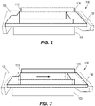
- FIGS. 7 and 8 illustrate a toner cartridge 300 in accordance with another embodiment of the invention.
- the toner cartridge 300 includes a cartridge engaging mechanism 375 that is similar to the engaging mechanism 175 described above with reference to FIGS. 1-6 , with like component being shown with reference numerals plus 200. Differences between the toner cartridges 100, 300 are described below.
- the second cartridge portion 335 of the toner cartridge 300 is moveable relative to the first cartridge portion 330 via the cartridge engaging mechanism 375. Specifically, the second cartridge portion 335 is moveable between a first position ( FIG. 7 ) and a second position ( FIG. 8 ) along the longitudinal axis 145 of the OPC drum 120. In the first position, the drive receiving member 340 is not engageable with the rotational driving member 15. In the second position ( FIG. 8 ), the drive receiving member 340 is engageable with the rotational driving member 15.
- the cartridge engaging mechanism 375 of the illustrated embodiment includes a guided body 385, a first guiding rail or member 380a disposed along one edge of the guided member 385, and a second guiding rail or member 380b disposed along an opposing edge of the guided body 385. Together, the guiding members 380a, 380b capture the guided body 385 of the second cartridge portion 335 for guided sliding movement therethrough.
- the cartridge engaging mechanism 375 further includes linkages 390 and a cam body 392 that is rotatable in response to manipulation (e.g., actuation) of the linkages 390.
- the linkages 390 and the cam body 392 are supported by the first cartridge portion 330.
- the linkages 390 and the cam body 392 facilitate guiding movement and controlling the distance travelled of the second cartridge portion 335 relative to first cartridge portion 330.
- the cam body 392 includes a first lobed portion 392a and a second lobed portion 392b that is larger (e.g., greater offset or apex from the rotational center of cam body 392) than the first lobed portion 392a.
- the cam body 392 is in sliding contact within a cam groove 394 of the guided body 385 to define a force transfer surface therebetween.
- the linkage 390 By actuating the linkage 390, the cam body 392 rotates through approximately 90 degrees. In one orientation ( FIG.
- the first lobed portion 392a is received in the cam groove 394 corresponding to the second cartridge portion 335 being in the first position.
- the second lobed portion 392b is received in the cam groove 394 corresponding to the second cartridge portion 335 being in the second position.
- a biasing member 396 is mounted on the first cartridge portion 330 to bias the second cartridge portion 335 toward the first position.
- cam body 392 of the illustrated embodiment is coupled to the first cartridge portion 330, in other embodiments, the cam body 392 may alternatively be supported on the second cartridge portion 335 where the cam body 392 interacts with a surface on the first cartridge portion 330 to move the second cartridge portion 335 between the first and second positions.
- the drive receiving member 340 and the driving member 15 are decoupled (i.e., there is no physical coupling of the driving member 15 and the drive receiving member 340 such that the driving member 15 and drive receiving member 340 are independently rotatable).
- the drive receiving member 340 is moved into mesh engagement with the driving member 15 of the printer 10 ( FIG. 8 ).
- a user may grasp and manipulate the linkage 390, which may be incorporated into the cartridge handle 102, to move the second cartridge portion 335 between the first and second positions.
- the supply of toner within the toner hopper 105 may begin to empty, in which case the current toner cartridge 300 should be removed from the printer 10 and replaced with a new toner cartridge 300.
- a user first manipulates the linkage 390 of the toner cartridge 300 in order to place the first lobed portion 392a in contact with the cam groove 394, permitting movement of the second cartridge portion 335 towards the first position and removing the mesh engagement between the rotational driving member 15 of the printer 10 and the drive receiving member 340 of the toner cartridge 300. At this point, it is safe to remove the toner cartridge 300 from the printer 10 without the risk of inadvertent damage to either of the drive receiving member 340 or the rotational driving member 15.
- the new toner cartridge 300 is inserted into the printer 10, where the user subsequently manipulates the linkage 390 to place the second lobed portion 392b in contact with the groove 394, thereby moving the second cartridge portion 335 toward the second position.
- the linkage 390 of this particular embodiment may function as the handle 102, may be incorporated into the handle 102, or may exist in addition to the handle 102 to facilitate carrying and maneuvering the cartridge 300.
- FIGS. 9 and 10 illustrate a toner cartridge 500 in accordance with another embodiment of the invention.
- the toner cartridge 500 includes a cartridge engaging mechanism 575 that is similar to the engaging mechanism 175 described above with reference to FIGS. 1-6 , with like component being shown with reference numerals plus 400. Differences between the toner cartridges 100, 500 are described below.
- the second cartridge portion 535 of the toner cartridge 500 is moveable relative to the first cartridge portion 530 via the cartridge engaging mechanism 575. Specifically, the second cartridge portion 535 is moveable between a first position ( FIG. 9 ) and a second position ( FIG. 10 ) along the longitudinal axis 145 of the OPC drum 120. In the first position, the drive receiving member 540 is not engageable with the rotational driving member 15. In the second position ( FIG. 10 ), the drive receiving member 540 is engageable with the rotational driving member 15.
- the cartridge engaging mechanism 575 of the illustrated embodiment includes a guided body 585, a first guiding rail or member 580a disposed along one edge of the guided body 585, and a second guiding rail or member 580b disposed along an opposing edge of the guided body 585. Together, the guiding members 580a, 580b capture the guided body 585 of the second cartridge portion 535 for guided sliding movement therethrough.
- the cartridge engaging mechanism 575 further includes a cam body 592 rotatably coupled to the first cartridge portion 530 and a post 590 disposed on the cam body 592.
- the cam body 592 is rotatable in response to manipulation of the post 590.
- the cam body 592 facilitates guiding movement and controlling the distance travelled of the second cartridge portion 535 relative to first cartridge portion 530.
- the cam body 592 includes a first lobed portion 592a and a second lobed portion 592b that is larger (e.g., greater offset or apex from the rotational center of cam body 592) than the first lobed portion 592a.
- the cam body 592 is in sliding contact within a cam groove 594 of the guide body 585 to define a force transfer surface therebetween.
- the cam body 592 is capable of rotating through approximately 90 degrees in response to manipulation of the post 590.
- the first lobed portion 592a is received in the cam groove 594 corresponding to the first position of the second cartridge portion 535.
- the second lobed portion 592b is received in the cam groove 594 corresponding to the second position of the second cartridge portion 535.
- a biasing member 596 is mounted on the first cartridge portion 530 to bias the second cartridge portion 535 toward the first position.
- cam body 592 of the illustrated embodiment is coupled to the first cartridge portion 530, in other embodiments, the cam body 592 may alternatively be supported on the second cartridge portion 535 where the cam body 592 interacts with a surface on the first cartridge portion 530 to move the second cartridge portion 535 between the first and second positions.
- the drive receiving member 540 and the driving member 15 are decoupled (i.e., there is no physical coupling of the driving member 15 and the drive receiving member 540 such that the driving member 15 and drive receiving member 540 are independently rotatable).
- the drive receiving member 540 is moved into mesh engagement with the driving member 15 of the printer 10 ( FIG. 8 ).
- the post 590 preferably is positioned such that upon installation of the cartridge into the printer 10, the post 590 interacts with a rigid surface within the printer, causing the cam body 592 to rotate just as the drive receiving member 540 moves into co-axial alignment with the rotational driving member 15. In this way, the cam body 592 is rotated from the position shown in FIG. 9 in which the drive receiving member 540 is not engageable with the rotational driving member 15, to the position shown in FIG. 10 in which the drive receiving member 540 is engageable with the rotational driving member 15, just as the cartridge 500 becomes fully seating in the printer 10.
- the supply of toner within the toner hopper 105 may begin to empty, in which case the current toner cartridge 500 should be removed from the printer 10 and replaced with a new toner cartridge 500.
- a user begins pulling the cartridge 500 out of the printer 10.
- the post 590 interacts with the rigid surface within the printer 10 which turns the cam body 592 and places the first lobed portion 592a in contact with the cam groove 594. This, in turn, causes movement of the second cartridge portion 535 towards the first position and removes the mesh engagement between the rotational driving member 15 of the printer 10 and the drive receiving member 540 of the toner cartridge 500.
- the new toner cartridge 500 is inserted into the printer 10, where the post 590 engages the rigid surface within the printer 10 which turns the cam body 592 to place the second lobed portion 592b in contact with the groove 594. This, in turn, moves the second cartridge portion 535 toward the second position.
- the toner cartridge 500 is also provided with the handle 102 to facilitate the insertion and removal process of the cartridge 500 relative to the printer 10.
- FIGS. 11 and 12 illustrate a toner cartridge 700 in accordance with another embodiment of the invention.
- the toner cartridge 700 includes a cartridge engaging mechanism 775 that is similar to the engaging mechanism 175 described above with reference to FIGS. 1-6 , with like component being shown with reference numerals plus 600. Differences between the toner cartridges 100, 700 are described below.
- the second cartridge portion 735 of the toner cartridge 700 is moveable relative to the first cartridge portion 730 via the cartridge engaging mechanism 775. Specifically, the second cartridge portion 735 is moveable between a first position ( FIG. 11 ) and a second position ( FIG. 12 ) along the longitudinal axis 145 of the OPC drum 120. In the first position, the drive receiving member 740 is not engageable with the rotational driving member 15. In the second position ( FIG. 12 ), the drive receiving member 740 is engageable with the rotational driving member 15.
- the cartridge engaging mechanism 775 of the illustrated embodiment includes a first ramped rail or guiding member 780a, a second ramped rail or guiding member 780b, and a guided body 785 having corresponding ramped edges that engage the first and second guiding members 780a, 780b. Together, the guiding members 780a, 780b capture the guided body 785 of the second cartridge portion 735 for guided sliding movement therethrough.
- the cartridge engaging mechanism 775 further includes a tab 790 connected to the first and second guiding members 780a, 780b. The tab 790 is user manipulable to cause movement of the guiding members 780a, 780b relative to the guided body 785. For example, the tab 790 is moveable from a first state ( FIG.
- the guided body 785 includes a pair of slots 792 that each receive a fastener 794 to limit the guided body 785 to lateral movement only.
- the slots 792 and fasteners 794 arrangement facilitates controlling the distance travelled of the second cartridge portion 735 relative to first cartridge portion 730.
- the tab 790 may define the cartridge handle 102 (see, e.g., Fig. 6 ). In other embodiments, the tab 790 may be incorporated into the handle 102 or coupled to the handle 102 via a linkage such that insertion and removal of the cartridge 700 via the handle actuates the cartridge engaging mechanism 775.
- the cartridge engaging mechanism 775 further includes a quick-release latch 797 configured to maintain the second cartridge portion 735 in the second position.
- the latch 797 is pivotably coupled to the first cartridge portion 730 and includes a protrusion 798 that is selectively receivable in an aperture 799 of the second cartridge portion 735.
- the protrusion 798 and the aperture 799 align when the second cartridge portion 735 is moved to the second position ( FIG. 12B ), such that the aperture 799 receives the protrusion 798.
- the latch 797 is pivoted away from the second cartridge portion 735 to remove the protrusion 798 of the latch 797 from the aperture 799 ( FIG.
- the latch 797 (and therefore the protrusion 798) is urged toward the second cartridge portion 735 via a biasing member (e.g., a torsion spring, etc.) to facilitate automatic insertion of the protrusion 735 into the aperture 799 when the second cartridge portion 735 is moved to the second position.
- a biasing member similar to the biasing member 596 illustrated in Figs. 9 and 10 may be incorporated to work in conjunction with the latch 797. For example, upon releasing the latch 797 during cartridge removal, the biasing member may urge the second cartridge portion 735 toward the first position ( FIG. 11 ) to disengage the drive receiving member 740 from the rotational driving member 15, thereby permitting removal of the cartridge 700.
- the drive receiving member 740 and the driving member 15 are decoupled (i.e., there is no physical coupling of the driving member 15 and the drive receiving member 340 such that the driving member 15 and drive receiving member 340 are independently rotatable).
- the drive receiving member 740 is moved into mesh engagement with the driving member 15 of the printer 10 ( FIG. 12A ).
- a user may grasp and manipulate the tab 790 to move the second cartridge portion 735 between the first and second positions.
- the supply of toner within the toner hopper 105 may begin to empty, in which case the current toner cartridge 700 should be removed from the printer 10 and replaced with a new toner cartridge 700.
- a user first manipulates the tab 790 of the toner cartridge 700 towards the first state, causing movement of the second cartridge portion 735 towards the first position and removing the mesh engagement between the rotational driving member 15 of the printer 10 and the drive receiving member 740 of the toner cartridge 700. At this point, it is safe to remove the toner cartridge 700 from the printer 10 without the risk of inadvertent damage to either of the drive receiving member 740 or the rotational driving member 15.
- the new toner cartridge 700 is inserted into the printer 10, where the user subsequently manipulates the tab 790 towards the second state, thereby moving the second cartridge portion 735 toward the second position.
- the tab 790 of this particular embodiment may serve to carry and maneuver the toner cartridge 700, whereas in other embodiments, the toner cartridge 700 is also provided with the handle 102 to facilitate carrying and maneuvering the cartridge 700.
Landscapes
- Physics & Mathematics (AREA)
- General Physics & Mathematics (AREA)
- Engineering & Computer Science (AREA)
- Computer Vision & Pattern Recognition (AREA)
- Electrophotography Configuration And Component (AREA)
- Dry Development In Electrophotography (AREA)
Claims (11)
- Cartouche d'imagerie (100, 300, 500, 700) pouvant être installée dans un dispositif de formation d'image, la cartouche d'imagerie ou le dispositif de formation d'image comprenant un tambour photoconducteur organique, le dispositif de formation d'image incluant un élément d'entraînement en rotation (15) et au moins un guide de cartouche définissant un chemin de guidage, la cartouche (100, 300, 500, 700) comprenant :une première partie de cartouche (130, 330, 530, 730) pouvant être mise en prise avec le au moins un guide de cartouche pour se déplacer le long du chemin de guidage ; etune seconde partie de cartouche (135, 335, 535, 735) couplée à la première partie de cartouche (130, 330, 530, 730), la seconde partie de cartouche (135, 335, 535, 735) incluant un élément de réception d'entraînement (140, 340, 540, 740) configuré pour mettre en prise l'élément d'entraînement en rotation (15) et au moins un du tambour photoconducteur organique (120), une trémie (105), un cylindre de développement (115), et une lame de régulation, la seconde partie de cartouche (135, 335, 535, 735) étant mobile relativement à la première partie de cartouche (130, 330, 530, 730) entre une première position dans laquelle l'élément de réception d'entraînement (140, 340, 540, 740) ne peut pas être mis en prise avec l'élément d'entraînement en rotation (15) et une seconde position dans laquelle l'élément de réception d'entraînement (140, 340, 540, 740) peut être mis en prise avec l'élément d'entraînement en rotation (15) ;caractérisée en ce que le tambour photoconducteur organique (120) définit un axe longitudinal (145), et dans lequel la seconde partie de cartouche (135, 335, 535, 735) se déplace par rapport à la première partie de cartouche (130, 330, 530, 730) dans une direction parallèle à l'axe longitudinal (145).
- Cartouche (100, 300, 500, 700) selon la revendication 1, dans laquelle l'élément de réception d'entraînement (140, 340, 540, 740) est fixé en translation et fixé en rotation au tambour photoconducteur organique (120).
- Cartouche (100, 300, 500, 700) selon la revendication 1, incluant en outre un mécanisme de mise en prise de cartouche (175, 375, 575, 775) pour déplacer la seconde partie de cartouche (135, 335, 535, 735) par rapport à la première partie de cartouche (130, 330, 530, 730).
- Cartouche (100, 300, 500, 700) selon la revendication 3, dans laquelle le mécanisme de mise en prise de cartouche (175, 375, 575, 775) inclut au moins un corps guidé (185, 385, 595, 785) et au moins un élément de guidage (180, 380, 580, 780) qui guide le mouvement de l'au moins un corps guidé (185, 385).
- Cartouche (100, 300, 500, 700) selon la revendication 3, dans laquelle le mécanisme de mise en prise de cartouche (175, 375, 575, 775) inclut une surface de transfert de force permettant de transférer et d'exercer une force depuis au moins une de la première partie de cartouche (130, 330, 530, 730) et de la seconde partie de cartouche (135, 335, 535, 735) pour déplacer la première partie de cartouche (130, 330, 530, 730).
- Cartouche (300, 500) selon la revendication 5, dans laquelle la surface de transfert de force est un corps de came (392, 592) disposé de manière mobile sur la première partie de cartouche (330, 530), dans laquelle le corps de came (392, 592) peut être mis en prise avec la seconde partie de cartouche (335, 535) pour permettre un mouvement de la seconde partie de cartouche (335, 535) entre la première position et la seconde position.
- Cartouche (300, 500) selon la revendication 6, dans laquelle le corps de came (392, 592) est un corps de came rotatif présentant une première partie lobée (392a, 592a) et une seconde partie lobée (392b, 592b), dans laquelle la seconde partie lobée (392b, 592b) est plus grande que la première partie lobée (392a, 592a).
- Cartouche (300, 500) selon la revendication 7, dans laquelle la seconde partie de cartouche (335, 535) se déplace vers la première position en réponse à une venue en butée entre la première partie lobée (392a, 592a) et la seconde partie de cartouche (335, 535), et dans laquelle la seconde partie de cartouche (335, 535) se déplace vers la seconde position en réponse à une venue en butée entre la seconde partie lobée (392b, 592b) et la seconde partie de cartouche (335, 535).
- Cartouche (700) selon la revendication 5, dans laquelle la surface de transfert de force est un rail incliné disposé de manière mobile sur la première partie de cartouche (730), dans lequel le rail incliné peut être mis en prise avec la seconde partie de cartouche (735) pour permettre un mouvement de la seconde partie de cartouche (735) entre la première position et la seconde position.
- Cartouche (300, 500, 700) selon la revendication 1, comprenant en outre un élément de polarisation (396, 596) pour pousser la seconde partie de cartouche (335, 535, 735) vers la première position.
- Cartouche (100, 300, 500, 700) selon la revendication 1, dans laquelle l'élément de réception d'entraînement (140, 340, 540, 740) et l'élément d'entraînement en rotation (15) sont découplés quand la seconde partie de cartouche (135, 335, 535, 735), et plus spécifiquement, le tambour photoconducteur organique (120) est dans la première position.
Applications Claiming Priority (2)
| Application Number | Priority Date | Filing Date | Title |
|---|---|---|---|
| US201862671163P | 2018-05-14 | 2018-05-14 | |
| PCT/US2019/032221 WO2019222218A1 (fr) | 2018-05-14 | 2019-05-14 | Cartouche d'imagerie à composants d'imagerie mobiles |
Publications (2)
| Publication Number | Publication Date |
|---|---|
| EP3791232A1 EP3791232A1 (fr) | 2021-03-17 |
| EP3791232B1 true EP3791232B1 (fr) | 2022-04-13 |
Family
ID=66690995
Family Applications (1)
| Application Number | Title | Priority Date | Filing Date |
|---|---|---|---|
| EP19728211.4A Not-in-force EP3791232B1 (fr) | 2018-05-14 | 2019-05-14 | Cartouche d'imagerie à composants d'imagerie mobiles |
Country Status (3)
| Country | Link |
|---|---|
| US (1) | US10649396B2 (fr) |
| EP (1) | EP3791232B1 (fr) |
| WO (1) | WO2019222218A1 (fr) |
Family Cites Families (6)
| Publication number | Priority date | Publication date | Assignee | Title |
|---|---|---|---|---|
| US8010011B2 (en) | 2005-07-05 | 2011-08-30 | Katun Corporation | Removably mountable frame for an image processsing apparatus, a removably mountable adaptor for an image processing apparatus and cartridges for use with a removably frame and removably mountable adaptor |
| JP4280769B2 (ja) | 2006-01-11 | 2009-06-17 | キヤノン株式会社 | 電子写真画像形成装置 |
| JP6004690B2 (ja) * | 2012-03-21 | 2016-10-12 | キヤノン株式会社 | プロセスカートリッジ及び画像形成装置 |
| JP6376749B2 (ja) | 2013-12-06 | 2018-08-22 | キヤノン株式会社 | プロセスカートリッジおよび電子写真画像形成装置 |
| US9329517B2 (en) | 2014-09-30 | 2016-05-03 | Clover Technologies Group, Llc | Drive receiving member for an imaging cartridge |
| BR122018074173B1 (pt) * | 2014-11-28 | 2023-12-19 | Canon Kabushiki Kaisha | Cartucho montável a um conjunto principal de aparelho de um aparelho formador de imagem |
-
2019
- 2019-05-14 EP EP19728211.4A patent/EP3791232B1/fr not_active Not-in-force
- 2019-05-14 US US16/412,000 patent/US10649396B2/en active Active
- 2019-05-14 WO PCT/US2019/032221 patent/WO2019222218A1/fr not_active Ceased
Also Published As
| Publication number | Publication date |
|---|---|
| US10649396B2 (en) | 2020-05-12 |
| US20190346807A1 (en) | 2019-11-14 |
| WO2019222218A1 (fr) | 2019-11-21 |
| EP3791232A1 (fr) | 2021-03-17 |
Similar Documents
| Publication | Publication Date | Title |
|---|---|---|
| JP4458642B2 (ja) | 画像形成装置 | |
| US6947687B2 (en) | Cartridge having locking portion for locking cartridge with an image forming apparatus and releasing portion to release the locking portion, and image forming apparatus having such a cartridge | |
| CN102193374B (zh) | 图像形成设备 | |
| EP3124411B1 (fr) | Dispositif d'alimentation de feuilles | |
| US9836020B2 (en) | Process cartridge with force receiving portion configured to receive a force to move a developing roller | |
| US11572240B2 (en) | Sheet feeding apparatus and image forming apparatus | |
| EP2975463B1 (fr) | Appareil de formation d'image | |
| US8059989B2 (en) | Color electrophotographic image forming apparatus with member supporting a plurality of cartridges | |
| EP3671351B1 (fr) | Appareil de formation d'images et procédé de remplacement d'unités de processus d'image dans un appareil de formation d'images | |
| EP1782130A2 (fr) | Sous-unite mobile et cartouche en deux parties pour dispositif de formation d'une image | |
| EP1849044B1 (fr) | Unite fonctionnelle et appareil de formation d'image incluant l'unite fonctionnelle | |
| US20160159590A1 (en) | Feeding device and image forming apparatus | |
| US10162290B2 (en) | Image forming apparatus | |
| US10656587B2 (en) | Sheet conveying device and image forming apparatus | |
| JP2019059559A (ja) | シート搬送装置及び画像形成装置 | |
| US9785095B2 (en) | Roller member, sheet feeding apparatus and image forming apparatus | |
| JP5110365B2 (ja) | 画像記録媒体供給装置および画像形成装置 | |
| CN100510987C (zh) | 图像形成装置以及处理单元 | |
| US10649396B2 (en) | Imaging cartridge with shiftable imaging components | |
| JP4444637B2 (ja) | 画像形成装置 | |
| JP2000298383A (ja) | 電子写真画像形成装置 | |
| JPH0553378A (ja) | 電子写真装置 | |
| US11914322B2 (en) | Drive coupler actuation via replaceable unit insertion in an image forming device | |
| JP2602317B2 (ja) | 画像形成装置 | |
| JP3607801B2 (ja) | 画像形成装置 |
Legal Events
| Date | Code | Title | Description |
|---|---|---|---|
| STAA | Information on the status of an ep patent application or granted ep patent |
Free format text: STATUS: UNKNOWN |
|
| STAA | Information on the status of an ep patent application or granted ep patent |
Free format text: STATUS: THE INTERNATIONAL PUBLICATION HAS BEEN MADE |
|
| PUAI | Public reference made under article 153(3) epc to a published international application that has entered the european phase |
Free format text: ORIGINAL CODE: 0009012 |
|
| STAA | Information on the status of an ep patent application or granted ep patent |
Free format text: STATUS: REQUEST FOR EXAMINATION WAS MADE |
|
| 17P | Request for examination filed |
Effective date: 20201207 |
|
| AK | Designated contracting states |
Kind code of ref document: A1 Designated state(s): AL AT BE BG CH CY CZ DE DK EE ES FI FR GB GR HR HU IE IS IT LI LT LU LV MC MK MT NL NO PL PT RO RS SE SI SK SM TR |
|
| AX | Request for extension of the european patent |
Extension state: BA ME |
|
| GRAP | Despatch of communication of intention to grant a patent |
Free format text: ORIGINAL CODE: EPIDOSNIGR1 |
|
| STAA | Information on the status of an ep patent application or granted ep patent |
Free format text: STATUS: GRANT OF PATENT IS INTENDED |
|
| INTG | Intention to grant announced |
Effective date: 20210514 |
|
| DAV | Request for validation of the european patent (deleted) | ||
| DAX | Request for extension of the european patent (deleted) | ||
| GRAJ | Information related to disapproval of communication of intention to grant by the applicant or resumption of examination proceedings by the epo deleted |
Free format text: ORIGINAL CODE: EPIDOSDIGR1 |
|
| STAA | Information on the status of an ep patent application or granted ep patent |
Free format text: STATUS: REQUEST FOR EXAMINATION WAS MADE |
|
| INTC | Intention to grant announced (deleted) | ||
| GRAP | Despatch of communication of intention to grant a patent |
Free format text: ORIGINAL CODE: EPIDOSNIGR1 |
|
| STAA | Information on the status of an ep patent application or granted ep patent |
Free format text: STATUS: GRANT OF PATENT IS INTENDED |
|
| GRAJ | Information related to disapproval of communication of intention to grant by the applicant or resumption of examination proceedings by the epo deleted |
Free format text: ORIGINAL CODE: EPIDOSDIGR1 |
|
| GRAP | Despatch of communication of intention to grant a patent |
Free format text: ORIGINAL CODE: EPIDOSNIGR1 |
|
| INTG | Intention to grant announced |
Effective date: 20211011 |
|
| INTG | Intention to grant announced |
Effective date: 20211027 |
|
| GRAS | Grant fee paid |
Free format text: ORIGINAL CODE: EPIDOSNIGR3 |
|
| GRAA | (expected) grant |
Free format text: ORIGINAL CODE: 0009210 |
|
| STAA | Information on the status of an ep patent application or granted ep patent |
Free format text: STATUS: THE PATENT HAS BEEN GRANTED |
|
| AK | Designated contracting states |
Kind code of ref document: B1 Designated state(s): AL AT BE BG CH CY CZ DE DK EE ES FI FR GB GR HR HU IE IS IT LI LT LU LV MC MK MT NL NO PL PT RO RS SE SI SK SM TR |
|
| REG | Reference to a national code |
Ref country code: GB Ref legal event code: FG4D |
|
| REG | Reference to a national code |
Ref country code: CH Ref legal event code: EP |
|
| REG | Reference to a national code |
Ref country code: DE Ref legal event code: R096 Ref document number: 602019013707 Country of ref document: DE |
|
| REG | Reference to a national code |
Ref country code: IE Ref legal event code: FG4D |
|
| REG | Reference to a national code |
Ref country code: AT Ref legal event code: REF Ref document number: 1483864 Country of ref document: AT Kind code of ref document: T Effective date: 20220515 |
|
| REG | Reference to a national code |
Ref country code: LT Ref legal event code: MG9D |
|
| REG | Reference to a national code |
Ref country code: NL Ref legal event code: MP Effective date: 20220413 |
|
| REG | Reference to a national code |
Ref country code: AT Ref legal event code: MK05 Ref document number: 1483864 Country of ref document: AT Kind code of ref document: T Effective date: 20220413 |
|
| PG25 | Lapsed in a contracting state [announced via postgrant information from national office to epo] |
Ref country code: NL Free format text: LAPSE BECAUSE OF FAILURE TO SUBMIT A TRANSLATION OF THE DESCRIPTION OR TO PAY THE FEE WITHIN THE PRESCRIBED TIME-LIMIT Effective date: 20220413 |
|
| PG25 | Lapsed in a contracting state [announced via postgrant information from national office to epo] |
Ref country code: SE Free format text: LAPSE BECAUSE OF FAILURE TO SUBMIT A TRANSLATION OF THE DESCRIPTION OR TO PAY THE FEE WITHIN THE PRESCRIBED TIME-LIMIT Effective date: 20220413 Ref country code: PT Free format text: LAPSE BECAUSE OF FAILURE TO SUBMIT A TRANSLATION OF THE DESCRIPTION OR TO PAY THE FEE WITHIN THE PRESCRIBED TIME-LIMIT Effective date: 20220816 Ref country code: NO Free format text: LAPSE BECAUSE OF FAILURE TO SUBMIT A TRANSLATION OF THE DESCRIPTION OR TO PAY THE FEE WITHIN THE PRESCRIBED TIME-LIMIT Effective date: 20220713 Ref country code: LT Free format text: LAPSE BECAUSE OF FAILURE TO SUBMIT A TRANSLATION OF THE DESCRIPTION OR TO PAY THE FEE WITHIN THE PRESCRIBED TIME-LIMIT Effective date: 20220413 Ref country code: HR Free format text: LAPSE BECAUSE OF FAILURE TO SUBMIT A TRANSLATION OF THE DESCRIPTION OR TO PAY THE FEE WITHIN THE PRESCRIBED TIME-LIMIT Effective date: 20220413 Ref country code: GR Free format text: LAPSE BECAUSE OF FAILURE TO SUBMIT A TRANSLATION OF THE DESCRIPTION OR TO PAY THE FEE WITHIN THE PRESCRIBED TIME-LIMIT Effective date: 20220714 Ref country code: FI Free format text: LAPSE BECAUSE OF FAILURE TO SUBMIT A TRANSLATION OF THE DESCRIPTION OR TO PAY THE FEE WITHIN THE PRESCRIBED TIME-LIMIT Effective date: 20220413 Ref country code: ES Free format text: LAPSE BECAUSE OF FAILURE TO SUBMIT A TRANSLATION OF THE DESCRIPTION OR TO PAY THE FEE WITHIN THE PRESCRIBED TIME-LIMIT Effective date: 20220413 Ref country code: BG Free format text: LAPSE BECAUSE OF FAILURE TO SUBMIT A TRANSLATION OF THE DESCRIPTION OR TO PAY THE FEE WITHIN THE PRESCRIBED TIME-LIMIT Effective date: 20220713 Ref country code: AT Free format text: LAPSE BECAUSE OF FAILURE TO SUBMIT A TRANSLATION OF THE DESCRIPTION OR TO PAY THE FEE WITHIN THE PRESCRIBED TIME-LIMIT Effective date: 20220413 |
|
| PG25 | Lapsed in a contracting state [announced via postgrant information from national office to epo] |
Ref country code: RS Free format text: LAPSE BECAUSE OF FAILURE TO SUBMIT A TRANSLATION OF THE DESCRIPTION OR TO PAY THE FEE WITHIN THE PRESCRIBED TIME-LIMIT Effective date: 20220413 Ref country code: PL Free format text: LAPSE BECAUSE OF FAILURE TO SUBMIT A TRANSLATION OF THE DESCRIPTION OR TO PAY THE FEE WITHIN THE PRESCRIBED TIME-LIMIT Effective date: 20220413 Ref country code: LV Free format text: LAPSE BECAUSE OF FAILURE TO SUBMIT A TRANSLATION OF THE DESCRIPTION OR TO PAY THE FEE WITHIN THE PRESCRIBED TIME-LIMIT Effective date: 20220413 Ref country code: IS Free format text: LAPSE BECAUSE OF FAILURE TO SUBMIT A TRANSLATION OF THE DESCRIPTION OR TO PAY THE FEE WITHIN THE PRESCRIBED TIME-LIMIT Effective date: 20220813 |
|
| REG | Reference to a national code |
Ref country code: DE Ref legal event code: R119 Ref document number: 602019013707 Country of ref document: DE |
|
| REG | Reference to a national code |
Ref country code: CH Ref legal event code: PL |
|
| REG | Reference to a national code |
Ref country code: BE Ref legal event code: MM Effective date: 20220531 |
|
| PG25 | Lapsed in a contracting state [announced via postgrant information from national office to epo] |
Ref country code: SM Free format text: LAPSE BECAUSE OF FAILURE TO SUBMIT A TRANSLATION OF THE DESCRIPTION OR TO PAY THE FEE WITHIN THE PRESCRIBED TIME-LIMIT Effective date: 20220413 Ref country code: SK Free format text: LAPSE BECAUSE OF FAILURE TO SUBMIT A TRANSLATION OF THE DESCRIPTION OR TO PAY THE FEE WITHIN THE PRESCRIBED TIME-LIMIT Effective date: 20220413 Ref country code: RO Free format text: LAPSE BECAUSE OF FAILURE TO SUBMIT A TRANSLATION OF THE DESCRIPTION OR TO PAY THE FEE WITHIN THE PRESCRIBED TIME-LIMIT Effective date: 20220413 Ref country code: MC Free format text: LAPSE BECAUSE OF FAILURE TO SUBMIT A TRANSLATION OF THE DESCRIPTION OR TO PAY THE FEE WITHIN THE PRESCRIBED TIME-LIMIT Effective date: 20220413 Ref country code: LU Free format text: LAPSE BECAUSE OF NON-PAYMENT OF DUE FEES Effective date: 20220514 Ref country code: LI Free format text: LAPSE BECAUSE OF NON-PAYMENT OF DUE FEES Effective date: 20220531 Ref country code: EE Free format text: LAPSE BECAUSE OF FAILURE TO SUBMIT A TRANSLATION OF THE DESCRIPTION OR TO PAY THE FEE WITHIN THE PRESCRIBED TIME-LIMIT Effective date: 20220413 Ref country code: DK Free format text: LAPSE BECAUSE OF FAILURE TO SUBMIT A TRANSLATION OF THE DESCRIPTION OR TO PAY THE FEE WITHIN THE PRESCRIBED TIME-LIMIT Effective date: 20220413 Ref country code: CZ Free format text: LAPSE BECAUSE OF FAILURE TO SUBMIT A TRANSLATION OF THE DESCRIPTION OR TO PAY THE FEE WITHIN THE PRESCRIBED TIME-LIMIT Effective date: 20220413 Ref country code: CH Free format text: LAPSE BECAUSE OF NON-PAYMENT OF DUE FEES Effective date: 20220531 |
|
| PLBE | No opposition filed within time limit |
Free format text: ORIGINAL CODE: 0009261 |
|
| STAA | Information on the status of an ep patent application or granted ep patent |
Free format text: STATUS: NO OPPOSITION FILED WITHIN TIME LIMIT |
|
| 26N | No opposition filed |
Effective date: 20230116 |
|
| PG25 | Lapsed in a contracting state [announced via postgrant information from national office to epo] |
Ref country code: AL Free format text: LAPSE BECAUSE OF FAILURE TO SUBMIT A TRANSLATION OF THE DESCRIPTION OR TO PAY THE FEE WITHIN THE PRESCRIBED TIME-LIMIT Effective date: 20220413 |
|
| PG25 | Lapsed in a contracting state [announced via postgrant information from national office to epo] |
Ref country code: IE Free format text: LAPSE BECAUSE OF NON-PAYMENT OF DUE FEES Effective date: 20220514 Ref country code: FR Free format text: LAPSE BECAUSE OF NON-PAYMENT OF DUE FEES Effective date: 20220613 |
|
| PG25 | Lapsed in a contracting state [announced via postgrant information from national office to epo] |
Ref country code: SI Free format text: LAPSE BECAUSE OF FAILURE TO SUBMIT A TRANSLATION OF THE DESCRIPTION OR TO PAY THE FEE WITHIN THE PRESCRIBED TIME-LIMIT Effective date: 20220413 Ref country code: DE Free format text: LAPSE BECAUSE OF NON-PAYMENT OF DUE FEES Effective date: 20221201 Ref country code: BE Free format text: LAPSE BECAUSE OF NON-PAYMENT OF DUE FEES Effective date: 20220531 |
|
| GBPC | Gb: european patent ceased through non-payment of renewal fee |
Effective date: 20230514 |
|
| PG25 | Lapsed in a contracting state [announced via postgrant information from national office to epo] |
Ref country code: IT Free format text: LAPSE BECAUSE OF FAILURE TO SUBMIT A TRANSLATION OF THE DESCRIPTION OR TO PAY THE FEE WITHIN THE PRESCRIBED TIME-LIMIT Effective date: 20220413 |
|
| PG25 | Lapsed in a contracting state [announced via postgrant information from national office to epo] |
Ref country code: MK Free format text: LAPSE BECAUSE OF FAILURE TO SUBMIT A TRANSLATION OF THE DESCRIPTION OR TO PAY THE FEE WITHIN THE PRESCRIBED TIME-LIMIT Effective date: 20220413 Ref country code: CY Free format text: LAPSE BECAUSE OF FAILURE TO SUBMIT A TRANSLATION OF THE DESCRIPTION OR TO PAY THE FEE WITHIN THE PRESCRIBED TIME-LIMIT Effective date: 20220413 Ref country code: GB Free format text: LAPSE BECAUSE OF NON-PAYMENT OF DUE FEES Effective date: 20230514 |
|
| PG25 | Lapsed in a contracting state [announced via postgrant information from national office to epo] |
Ref country code: HU Free format text: LAPSE BECAUSE OF FAILURE TO SUBMIT A TRANSLATION OF THE DESCRIPTION OR TO PAY THE FEE WITHIN THE PRESCRIBED TIME-LIMIT; INVALID AB INITIO Effective date: 20190514 |
|
| PG25 | Lapsed in a contracting state [announced via postgrant information from national office to epo] |
Ref country code: TR Free format text: LAPSE BECAUSE OF FAILURE TO SUBMIT A TRANSLATION OF THE DESCRIPTION OR TO PAY THE FEE WITHIN THE PRESCRIBED TIME-LIMIT Effective date: 20220413 |
|
| PG25 | Lapsed in a contracting state [announced via postgrant information from national office to epo] |
Ref country code: MT Free format text: LAPSE BECAUSE OF FAILURE TO SUBMIT A TRANSLATION OF THE DESCRIPTION OR TO PAY THE FEE WITHIN THE PRESCRIBED TIME-LIMIT Effective date: 20220413 |
|
| PG25 | Lapsed in a contracting state [announced via postgrant information from national office to epo] |
Ref country code: BG Free format text: LAPSE BECAUSE OF FAILURE TO SUBMIT A TRANSLATION OF THE DESCRIPTION OR TO PAY THE FEE WITHIN THE PRESCRIBED TIME-LIMIT Effective date: 20220413 |
|
| PG25 | Lapsed in a contracting state [announced via postgrant information from national office to epo] |
Ref country code: BG Free format text: LAPSE BECAUSE OF FAILURE TO SUBMIT A TRANSLATION OF THE DESCRIPTION OR TO PAY THE FEE WITHIN THE PRESCRIBED TIME-LIMIT Effective date: 20220413 |