EP3791836A1 - Dispositif d'injection intravitréenne dans un il - Google Patents
Dispositif d'injection intravitréenne dans un il Download PDFInfo
- Publication number
- EP3791836A1 EP3791836A1 EP19196643.1A EP19196643A EP3791836A1 EP 3791836 A1 EP3791836 A1 EP 3791836A1 EP 19196643 A EP19196643 A EP 19196643A EP 3791836 A1 EP3791836 A1 EP 3791836A1
- Authority
- EP
- European Patent Office
- Prior art keywords
- housing
- receptacle
- eye
- injection
- injection needle
- Prior art date
- Legal status (The legal status is an assumption and is not a legal conclusion. Google has not performed a legal analysis and makes no representation as to the accuracy of the status listed.)
- Withdrawn
Links
- 238000002347 injection Methods 0.000 title claims abstract description 105
- 239000007924 injection Substances 0.000 title claims abstract description 105
- 210000000795 conjunctiva Anatomy 0.000 claims abstract description 31
- 239000012530 fluid Substances 0.000 claims abstract description 22
- 239000003814 drug Substances 0.000 claims abstract description 18
- 238000006073 displacement reaction Methods 0.000 claims description 18
- 239000011324 bead Substances 0.000 claims description 5
- 229920001971 elastomer Polymers 0.000 claims description 3
- 239000000806 elastomer Substances 0.000 claims description 3
- 210000001508 eye Anatomy 0.000 description 67
- 229940079593 drug Drugs 0.000 description 6
- 239000000463 material Substances 0.000 description 6
- 230000035515 penetration Effects 0.000 description 6
- 238000012377 drug delivery Methods 0.000 description 5
- 210000000744 eyelid Anatomy 0.000 description 5
- 238000004659 sterilization and disinfection Methods 0.000 description 5
- 238000004806 packaging method and process Methods 0.000 description 4
- 230000001954 sterilising effect Effects 0.000 description 4
- 239000004480 active ingredient Substances 0.000 description 3
- 239000000645 desinfectant Substances 0.000 description 3
- 239000000203 mixture Substances 0.000 description 3
- 210000001525 retina Anatomy 0.000 description 3
- ZCYVEMRRCGMTRW-UHFFFAOYSA-N 7553-56-2 Chemical compound [I] ZCYVEMRRCGMTRW-UHFFFAOYSA-N 0.000 description 2
- 230000000694 effects Effects 0.000 description 2
- 238000001746 injection moulding Methods 0.000 description 2
- PNDPGZBMCMUPRI-UHFFFAOYSA-N iodine Chemical compound II PNDPGZBMCMUPRI-UHFFFAOYSA-N 0.000 description 2
- 229910052740 iodine Inorganic materials 0.000 description 2
- 239000011630 iodine Substances 0.000 description 2
- 238000004519 manufacturing process Methods 0.000 description 2
- 229920002379 silicone rubber Polymers 0.000 description 2
- 239000000126 substance Substances 0.000 description 2
- 241000894006 Bacteria Species 0.000 description 1
- 208000001344 Macular Edema Diseases 0.000 description 1
- 206010025415 Macular oedema Diseases 0.000 description 1
- 206010057430 Retinal injury Diseases 0.000 description 1
- 208000027418 Wounds and injury Diseases 0.000 description 1
- 206010064930 age-related macular degeneration Diseases 0.000 description 1
- 230000003444 anaesthetic effect Effects 0.000 description 1
- 230000000740 bleeding effect Effects 0.000 description 1
- 210000005252 bulbus oculi Anatomy 0.000 description 1
- 239000011248 coating agent Substances 0.000 description 1
- 238000000576 coating method Methods 0.000 description 1
- 230000001419 dependent effect Effects 0.000 description 1
- 230000000249 desinfective effect Effects 0.000 description 1
- 206010012601 diabetes mellitus Diseases 0.000 description 1
- 210000004709 eyebrow Anatomy 0.000 description 1
- 210000000720 eyelash Anatomy 0.000 description 1
- 208000015181 infectious disease Diseases 0.000 description 1
- 238000003780 insertion Methods 0.000 description 1
- 230000037431 insertion Effects 0.000 description 1
- 239000007788 liquid Substances 0.000 description 1
- 238000002690 local anesthesia Methods 0.000 description 1
- 230000007774 longterm Effects 0.000 description 1
- 208000002780 macular degeneration Diseases 0.000 description 1
- 201000010230 macular retinal edema Diseases 0.000 description 1
- 238000000034 method Methods 0.000 description 1
- 210000000056 organ Anatomy 0.000 description 1
- 239000000825 pharmaceutical preparation Substances 0.000 description 1
- 229940127557 pharmaceutical product Drugs 0.000 description 1
- 238000004904 shortening Methods 0.000 description 1
- 230000008961 swelling Effects 0.000 description 1
- 229920001169 thermoplastic Polymers 0.000 description 1
- 229920001187 thermosetting polymer Polymers 0.000 description 1
- 239000004416 thermosoftening plastic Substances 0.000 description 1
- 230000007704 transition Effects 0.000 description 1
- 210000003462 vein Anatomy 0.000 description 1
Images


Classifications
-
- A—HUMAN NECESSITIES
- A61—MEDICAL OR VETERINARY SCIENCE; HYGIENE
- A61F—FILTERS IMPLANTABLE INTO BLOOD VESSELS; PROSTHESES; DEVICES PROVIDING PATENCY TO, OR PREVENTING COLLAPSING OF, TUBULAR STRUCTURES OF THE BODY, e.g. STENTS; ORTHOPAEDIC, NURSING OR CONTRACEPTIVE DEVICES; FOMENTATION; TREATMENT OR PROTECTION OF EYES OR EARS; BANDAGES, DRESSINGS OR ABSORBENT PADS; FIRST-AID KITS
- A61F9/00—Methods or devices for treatment of the eyes; Devices for putting in contact-lenses; Devices to correct squinting; Apparatus to guide the blind; Protective devices for the eyes, carried on the body or in the hand
- A61F9/0008—Introducing ophthalmic products into the ocular cavity or retaining products therein
- A61F9/0017—Introducing ophthalmic products into the ocular cavity or retaining products therein implantable in, or in contact with, the eye, e.g. ocular inserts
-
- A—HUMAN NECESSITIES
- A61—MEDICAL OR VETERINARY SCIENCE; HYGIENE
- A61F—FILTERS IMPLANTABLE INTO BLOOD VESSELS; PROSTHESES; DEVICES PROVIDING PATENCY TO, OR PREVENTING COLLAPSING OF, TUBULAR STRUCTURES OF THE BODY, e.g. STENTS; ORTHOPAEDIC, NURSING OR CONTRACEPTIVE DEVICES; FOMENTATION; TREATMENT OR PROTECTION OF EYES OR EARS; BANDAGES, DRESSINGS OR ABSORBENT PADS; FIRST-AID KITS
- A61F9/00—Methods or devices for treatment of the eyes; Devices for putting in contact-lenses; Devices to correct squinting; Apparatus to guide the blind; Protective devices for the eyes, carried on the body or in the hand
- A61F9/0008—Introducing ophthalmic products into the ocular cavity or retaining products therein
- A61F9/0026—Ophthalmic product dispenser attachments to facilitate positioning near the eye
Definitions
- the present invention relates to a device for intravitreal injection into an eye.
- the device includes a housing having a proximal end and a distal end.
- a first receptacle is arranged at the proximal end of the housing.
- the first receptacle is designed to receive an injection needle to which a first syringe body with a medicament contained therein can be fastened.
- At the distal end of the housing there is a circumferential contact surface for contacting the device against a region of the conjunctiva of the eye.
- the first receptacle can be displaced in the direction of the contact surface in such a way that an injection needle arranged in the receptacle can penetrate the eye and the medicament located in the first syringe body can be injected into the eye.
- iodine-containing pharmaceutical products are used, among other things, to disinfect the eye and the area adjacent to it, such as the eyelids, eyelashes and eyebrows.
- This sterilization method requires additional consumables and an increased expenditure of time. The associated longer operation time can increase the risk of complications.
- the drug delivery device enables local disinfection of the eye in the area of the puncture site of an injection needle.
- the drug delivery device includes a body for receiving a cartridge containing a drug and a reservoir coupled to the body.
- the reservoir contains a fluid, such as a disinfectant, and a piston.
- the cartridge is connected to a hypodermic needle and is axially movable relative to the body between a retracted position and an extended position. After placing the device on the conjunctiva of the eye, the cartridge is moved axially from the retracted position to the extended position. As a result, the piston is also moved axially and the disinfectant is pumped out of the reservoir towards the eye.
- the disinfectant covers the puncture area the injection needle and disinfects it before the injection needle penetrates the eye.
- the drug delivery device is simply placed on the conjunctiva during injection. Slipping of the drug delivery device relative to the conjunctiva is possible, which is why adequate sterilization of the injection site cannot be guaranteed.
- the one from the pending European patent application EP 19155658.8 known device avoids this disadvantage.
- the device has a housing which has a vacuum chamber. By applying a negative pressure in the negative pressure chamber, the housing is sucked onto the eye.
- the housing further comprises a reservoir in which a fluid is arranged. By applying a negative pressure, the fluid is pumped out of the reservoir and distributed over the eye within the housing.
- the manufacture of the device is complex and costly.
- the housing comprises a negative pressure chamber which is open towards the distal end of the housing in such a way that a negative pressure generated in the negative pressure chamber sucks the contact surface of the housing against the eye.
- a second receptacle for a second syringe body with a fluid contained therein is arranged at the proximal end of the housing.
- the second receptacle is connected to the negative pressure chamber in such a way that the fluid is distributed within the contact surface on the eye after it has been dispensed from a second syringe body arranged in the second receptacle.
- the negative pressure preferably serves as a first fixing aid until the fluid is released.
- an additional manual fixation of the housing of the device on the eye is optionally necessary.
- the negative pressure in the negative pressure chamber can no longer be sufficient to fix the housing independently on the conjunctiva.
- the fluid preferably has disinfecting and / or anesthetic properties. For example, PVD iodine is used as the fluid.
- the device can be designed as a disposable device or be suitable for multiple use. If the device is to be used several times, it is designed in such a way that it can be sterilized after each use.
- the device is preferably sold sterile in packaging.
- negative pressure is understood to mean a pressure which is below the ambient pressure of 1 bar.
- vacuum chamber is understood to mean a chamber in which the ambient pressure can be reduced from 1 bar and is in a range between 0 bar and 1 bar.
- syringe body is understood to mean a hollow-cylindrical body to which an injection needle (cannula) can be attached and connected to it.
- a syringe plunger which can be displaced by means of a plunger which can be actuated from the rear, is arranged displaceably in a cavity of the syringe body.
- the cavity can, for example, receive a drug in liquid form, which can be conveyed out of the cavity and thus out of the syringe body by actuating the plunger and injected into a body with the aid of the injection needle.
- the vacuum chamber has a flexible, manually deformable wall area, the vacuum chamber being designed in such a way that, by deforming the wall area, the volume of the vacuum chamber can be reduced, starting from an original size, and the volume of the Vacuum chamber returns to its original size.
- the housing has a displacement axis along which the first receptacle can be displaced in the direction of the contact surface.
- the wall area preferably has a wall which is convexly shaped radially outward from the displacement axis of the housing.
- the flexible wall area is grasped by a doctor with one hand and flexibly deformed so that the volume of the negative pressure chamber is reduced relative to an original size.
- the air escaping from the vacuum chamber is preferably conveyed out of the latter via a distal opening of the vacuum chamber or of the housing provided within the contact surface.
- the doctor loosens his grip around the flexible wall area at least partially, so that it is at least partially flexible and deforms back to its original size again. and thereby generating a negative pressure in the negative pressure chamber.
- the housing and in particular the flexible, manually deformable wall area are preferably ergonomically shaped. This enables safe handling of the device.
- the housing has a displacement device, by means of which the first receptacle is guided along the displacement axis, which extends from the proximal end to the distal end of the housing, from a rest position to an injection position, with one in The injection needle arranged in the first receptacle is spaced apart from the eye in the rest position and has penetrated the eye in the injection position.
- a displacement device by means of which the first receptacle is guided along the displacement axis, which extends from the proximal end to the distal end of the housing, from a rest position to an injection position, with one in The injection needle arranged in the first receptacle is spaced apart from the eye in the rest position and has penetrated the eye in the injection position.
- the housing has a limitation of the travel path from the retracted to the extended position of the receptacle.
- the device is preferably grasped manually by a doctor while the first receptacle is being moved from the rest position to the injection position, in order to additionally secure the device from slipping relative to the eye.
- the displacement device preferably comprises a bellows-like structure.
- a bellows-like structure enables a controlled folding of individual bellows elements and thus a shortening of the structure during the displacement of the first receptacle from the rest position to the injection position.
- the bellows-like structure is an accordion-like section of the Housing formed.
- the housing preferably has an accordion-like wall in the accordion-like section.
- the accordion-like wall can have one or more cross struts transverse to the displacement axis of the housing in order to prevent the wall from collapsing.
- the cross braces can have one or more through holes through which the injection needle protrudes.
- the housing preferably has a cylindrical recess in which the accordion-like section is arranged.
- the depression additionally stabilizes the accordion-like section and prevents it from tilting in an uncontrolled manner.
- the accordion-like section preferably has individual wall elements that can be folded over one another.
- the accordion-like section is completely compressed in the injection position.
- the individual foldable wall elements preferably lie approximately parallel to one another in the injection position. This ensures that the travel path of the injection needle from the rest position into the injection position of the first receptacle is limited. This enables a precise penetration depth of the injection needle into the eye. Improper penetration of the injection needle into the eye, that is, for example, too deep penetration or oblique penetration, is thus avoided.
- the accordion-like section of the housing preferably forms a reset mechanism for at least partially automatic movement of the first recording from the injection position to the rest position.
- the accordion-like section can optionally have a spring stiffness, so that when moving the first receptacle from the rest position to the injection position, a spring force has to be overcome which pushes the first receptacle back towards the rest position when it is released. As a result, a safe and quick withdrawal of the injection needle from the eye can optionally be guaranteed.
- the negative pressure chamber has a through opening on a side opposite the contact surface, via which the negative pressure chamber is connected to the first receptacle and through which the injection needle protrudes in the rest position of the first receptacle.
- the through opening guides the injection needle in the housing. This ensures that the injection needle enters the eye at approximately a right angle to the conjunctiva.
- the housing is molded in one piece and is preferably made from an elastomer.
- the housing is preferably manufactured using an injection molding process.
- a single material or mixture of materials is optionally used, for example silicone elastomers.
- the material must be sufficiently flexible to enable, for example, a deformation of the wall area of the vacuum chamber and / or a deformation of the accordion-like section of the housing.
- the material / mixture of materials used must ensure sufficient strength of the housing so that the housing as a whole does not inadvertently deform when the fluid is dispensed from a second syringe body inserted into the second receptacle or when the first receptacle is moved into the injection position.
- the housing preferably has a positioning device at the distal end for positioning the device on the conjunctiva of the eye. This ensures that the doctor can easily and specifically position the device in the correct position on the conjunctiva of the eye. This ensures a safe intravitreal injection at a sufficient distance from relevant intraocular structures.
- the positioning device is designed as an outer contour at the distal end of the housing, the outer contour being shaped in such a way that it is at least partially modeled on an outer contour of an iris. This enables the device to be easily positioned on the conjunctiva of the eye. If the outer contour of the distal end of the housing is at least partially modeled on an outer contour of an iris, the doctor only needs to superimpose the outer contour of the housing with the outer contour of the iris in order to position the device correctly on the conjunctiva of the eye. This ensures that the device is positioned more quickly and easily on the conjunctiva of the eye.
- the positioning device is designed as a colored marking of the housing.
- the colored marking can be provided in the area of the contact surface and identify an area in which the housing is intended to overlap the iris.
- the positioning device is preferably designed as a flat colored marking on the housing.
- the colored area marking can also be a colored area of the wall of the housing.
- several colored markings are provided on the housing that are rotationally symmetrical to the displacement axis.
- two colored markings rotated by 180 ° around the displacement axis are provided on the housing.
- the device preferably has an insert which is inserted into the first receptacle of the housing, the insert tapering from the proximal end to the distal end of the housing.
- the injection needle can be inserted into the first receptacle of the housing by the doctor himself before using the device. The use ensures that the needle is guided so that it is easy and can be quickly inserted into the first receptacle without damaging the housing.
- the insert and the housing are made of different materials. Cured silicone elastomers, thermosetting plastics or thermoplastics, among others, are preferably used to manufacture the insert.
- the device is preferably sold together with an insert mounted in the first receptacle.
- the first receptacle comprises a circumferential bead which is designed to interact with a circumferential groove provided on the insert in such a way that the insert is fixed in the first receptacle.
- the form-fitting connection by means of a bead and groove is a simple and safe way to fix the insert in the housing.
- the device further comprises an injection needle which is arranged in the first receptacle.
- an injection needle is inserted into the first receptacle and fixed there with a force fit.
- the device is sterilized and packaged together with the injection needle.
- the doctor Before using the device, the doctor only has to remove the device with the injection needle from the packaging and insert first and second syringe bodies, which contain the medicament or the fluid to be administered, into the first and second receptacles of the housing, respectively. This enables easy handling of the device.
- the injection system comprises a device according to the invention for intravitreal injection into an eye and an injection needle which is arranged in the first receptacle of the housing.
- the injection system further comprises a first syringe body, which is connected to the injection needle, and a second syringe body, which is arranged in the second receptacle of the housing.
- the injection system is optionally available as a multi-part set so that the doctor to be treated has all the necessary elements of the injection system at hand.
- the injection system can be made ready for use quickly and inexpensively without first searching for the required syringe bodies or injection needles.
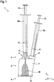
- an injection system 1 comprising a device 2 for intravitreal injection into an eye 3 is shown.
- the device 2 comprises a housing 4 with a proximal end 5 and a distal end 6.
- a first receptacle 7 and a second receptacle 8 are arranged at the proximal end 5 of the housing 5.
- the housing is molded in one piece by means of injection molding and is preferably made from an elastomer.
- the device 2 further comprises an injection needle 9 which is arranged in the first receptacle 7.
- a first syringe body 10a of the injection system 1 with a medicament contained therein is fastened to the injection needle 8.
- the injection system 1 further comprises a second syringe body 10b with a fluid contained therein, which is arranged in the second receptacle 8 of the housing 4.
- the syringe bodies 10a, 10b each have a piston 11 and a plunger 12, by means of which the medicament or the fluid, for example iodine, can be conveyed out of the respective syringe body 10a, 10b.
- a circular, circumferential contact surface 13 is provided for the device 2 to contact a region of the conjunctiva 14 of the eye 3.
- the housing has a displacement device 15 by means of which the first receptacle 7 moves along a displacement axis 16, which extends from the proximal end 5 to the distal end 6 of the housing 4, from a rest position to an injection position is slidably guided.
- the injection needle 6 arranged in the first receptacle 7 is spaced apart from the eye 3 in the rest position and penetrated into the eye 3 in the injection position.
- the first receptacle 7 is thus displaceable in the direction of the contact surface 13 in such a way that the injection needle 9 arranged in the first receptacle 7 can penetrate into the eye 3 and the medicament located in the first syringe body 10a can be injected into the eye 3.
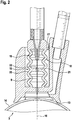
- the displacement device 16 is arranged in a cylindrical recess 17 in the housing 4. It comprises a bellows-like structure which is designed as an accordion-like section 18 of the housing 4.
- the housing has an accordion-like wall 19 with wall elements 20 that can be folded over one another. In the injection position, the foldable wall elements 20 lie approximately parallel on top of one another.
- the accordion-like wall 19 has a cross brace 21 which is arranged transversely to the displacement axis 16 of the housing 4.
- the cross brace 21 comprises a through hole 22 through which the injection needle 9 protrudes.
- the housing 4 further comprises a negative pressure chamber 23 which has an opening 24 towards the distal end 6 of the housing 4.
- the negative pressure chamber 23 is opened in such a way that a negative pressure generated in the negative pressure chamber 23 sucks the contact surface 13 of the housing 4 against the eye 3.
- the vacuum chamber 23 has a flexible, manually deformable wall area 25, the vacuum chamber 23 being designed in such a way that the volume of the vacuum chamber 23, starting from an original size, can be reduced by deforming the wall area 25 and the volume of the Vacuum chamber 23 resumes its original size.
- the negative pressure chamber 23 has a through opening 26 on a side opposite the contact surface 13, via which the negative pressure chamber 23 is connected to the first receptacle 7 and through which the injection needle 9 protrudes in the rest position of the first receptacle 7.
- the second receptacle 8 is connected to the vacuum chamber 23 in such a way that the fluid located in the second syringe body 10b is distributed within the contact surface 13 on the eye 3 after it has been dispensed from the second syringe body 10b.
- Figure 4 shows a schematic representation of an eye 3 with the conjunctiva 14 and a distal end 6 of the housing 4 of the device 2 placed on the conjunctiva 14 in section along the line AA from FIG Figure 3 .
- the housing 4 has a positioning device 27 for positioning the device 2 on the conjunctiva 14 of the eye 3.
- the positioning device 27 is shown as a colored marking 28 ( Figure 1 ) formed on the housing 4.
- the colored marking 28 is in Figure 4 for a simplified representation shown as an additional layer 30 on the outer contour 29.
- the housing 4 can be colored through in the area of the colored marking 28.
- the colored marking 28 is applied to the outer contour 29 of the housing 4, which is circular in the area of the distal end 6, in such a way that it color-coded an overlap area in which the outer contour 29 is intended to overlap an iris 30 of the eye 3. If the colored marking 28 overlaps the iris 31 and the outer contour 29 of the housing 4 comes to rest against the eyelids 32 of the eye 3, the device 2 and thus the injection needle 9 are correctly positioned relative to the eye 3.
- Figure 5 shows a second embodiment of the positioning device 27 at the distal end 10 of the device 2.
- the positioning device 27 ′ differs from that shown in FIG. 4 in that it is designed as an outer contour 29 ′ at the distal end 6 of the housing 4.
- the outer contour 29 ′ is shaped in such a way that it is at least partially modeled on an outer contour of the iris 31 of the eye 3 and at least partially a course of a transition between the eyelids 32 and the conjunctiva 14 of the eye 3.
- the outer contour 29 ′ comprises two opposite concave sections 33, which are modeled on the outer contour of the iris 31, and two opposite convex sections 34 which connect the concave sections 33 to one another.
- the doctor removes the device 1 from a sterile packaging.
- the injection needle 9 is already arranged in the first receptacle 7.
- the doctor draws a first syringe body 10a with a drug and attaches the first syringe body 10a to the injection needle 9.
- the doctor then draws a second syringe body 10b with a fluid, such as iodine, and places the second syringe body 10b in the second receptacle 8 of the housing 4, so that it is fixed in the second receptacle 8 with a force fit.
- a fluid such as iodine
- the doctor then grips around the flexible wall area 25 of the negative pressure chamber 23 with one hand and deforms it manually in such a way that the volume of the negative pressure chamber 23 is reduced and the air in the vacuum chamber 23 at least partially escapes through the opening 24 surrounded by the contact surface 13.
- the contact surface 13 is then placed on the conjunctiva 14 of an eye 3 and the housing 4 is positioned on the conjunctiva 14 using the colored marking 28 or using the outer contour 29 ′.
- the doctor continues to hold the device 2 with one hand and actuates the plunger 12 of the second syringe body 10b in such a way that the fluid located therein moves in the direction of the negative pressure chamber 23 and is distributed on the conjunctiva 14 within the circumferential contact surface 13 of the housing 4.
- the fluid disinfects or anesthetizes the conjunctiva 14 in the area of the opening 24.
- the plunger 12 By actuating the plunger 12, the negative pressure in the negative pressure chamber 23 is reduced. Therefore, one-handed fixation of the device 2 by the doctor is necessary to prevent the device 2 from slipping unintentionally the conjunctiva 124 to prevent.
- the foldable wall elements 30 fold over one another, so that these approximately parallel wall elements lie one on top of the other.
- the injection needle 9 penetrates the conjunctiva 14 of eye 3 a. If the foldable wall elements 30 lie approximately parallel on top of one another, the injection position and thus the maximum depth of penetration of the injection needle 9 into the eye 3 has been reached.
- the plunger 12 and thus the piston 11 are actuated relative to the first syringe body 10a, so that the medicament located in the first syringe body 10a is injected into the eye 3 via the injection needle 9.
- the negative pressure in the negative pressure chamber 23 is completely reduced and ambient pressure prevails in the negative pressure chamber 23.
- the device 2 is lifted manually from the eye 20 and the injection needle 9 is thus pulled out of the eye 3. Since the internal pressure in the eye 3 is higher than the ambient pressure, the entry wound of the injection needle 9 is closed immediately after it is withdrawn from the eye 3.
- FIG. 6 a second embodiment of the device 2 is shown in section.
- the device 2 'differs from that in FIGS Figures 1 to 5 shown in that it has an insert 35.
- the insert 35 is inserted into the first receptacle 7 of the housing 4 and tapers starting from the proximal end 5 to the distal end 6 of the housing 4.
- the insert 35 protrudes into the accordion-like section 18 of the housing 4 and runs through the through hole 22 in the cross brace 21 of the accordion-like wall 19.
- the first receptacle 7 comprises a circumferential bead 36 which is designed to interact with a circumferential groove 37 provided on the insert 35 in such a way that the insert 35 is fixed in the first receptacle 7.
- the first receptacle 7 and the insert 35 are therefore connected to one another in a form-fitting manner.
- the device 2 ′ has a through opening 26 which is larger in diameter in the vacuum chamber 23.
- the device 2 ' is in sterile packaging without an injection needle 9 ( Figure 2 ) expelled.
- the injection needle 9 is inserted into the first receptacle 7 by the attending physician himself.
- the doctor inserts the injection needle 9 through the first receptacle 7 into the insert 35 and fixes the injection needle 9 in the first receptacle 7 in a non-positive manner.
- the insert 35 guides the injection needle 9 in such a way that it is aligned along the displacement axis 16.
Landscapes
- Health & Medical Sciences (AREA)
- Ophthalmology & Optometry (AREA)
- Engineering & Computer Science (AREA)
- Biomedical Technology (AREA)
- Heart & Thoracic Surgery (AREA)
- Vascular Medicine (AREA)
- Life Sciences & Earth Sciences (AREA)
- Animal Behavior & Ethology (AREA)
- General Health & Medical Sciences (AREA)
- Public Health (AREA)
- Veterinary Medicine (AREA)
- Infusion, Injection, And Reservoir Apparatuses (AREA)
Priority Applications (1)
| Application Number | Priority Date | Filing Date | Title |
|---|---|---|---|
| EP19196643.1A EP3791836A1 (fr) | 2019-09-11 | 2019-09-11 | Dispositif d'injection intravitréenne dans un il |
Applications Claiming Priority (1)
| Application Number | Priority Date | Filing Date | Title |
|---|---|---|---|
| EP19196643.1A EP3791836A1 (fr) | 2019-09-11 | 2019-09-11 | Dispositif d'injection intravitréenne dans un il |
Publications (1)
| Publication Number | Publication Date |
|---|---|
| EP3791836A1 true EP3791836A1 (fr) | 2021-03-17 |
Family
ID=67928675
Family Applications (1)
| Application Number | Title | Priority Date | Filing Date |
|---|---|---|---|
| EP19196643.1A Withdrawn EP3791836A1 (fr) | 2019-09-11 | 2019-09-11 | Dispositif d'injection intravitréenne dans un il |
Country Status (1)
| Country | Link |
|---|---|
| EP (1) | EP3791836A1 (fr) |
Cited By (3)
| Publication number | Priority date | Publication date | Assignee | Title |
|---|---|---|---|---|
| CN117281684A (zh) * | 2023-11-24 | 2023-12-26 | 超目科技(北京)有限公司 | 眼球吸附装置和眼球吸附系统 |
| EP4531775A1 (fr) | 2022-06-02 | 2025-04-09 | Medical Research Development Fund for Health Services Poriya Hospital | Seringue oculaire et procédé |
| WO2026064304A1 (fr) * | 2024-09-17 | 2026-03-26 | D&D Biopharmaceuticals, Llc | Dispositifs déflecteurs pour l'administration de compositions thérapeutiques à l'oeil |
Citations (1)
| Publication number | Priority date | Publication date | Assignee | Title |
|---|---|---|---|---|
| EP2578191A1 (fr) | 2011-10-07 | 2013-04-10 | Sanofi-Aventis Deutschland GmbH | Appareil pour injection intraoculaire |
-
2019
- 2019-09-11 EP EP19196643.1A patent/EP3791836A1/fr not_active Withdrawn
Patent Citations (1)
| Publication number | Priority date | Publication date | Assignee | Title |
|---|---|---|---|---|
| EP2578191A1 (fr) | 2011-10-07 | 2013-04-10 | Sanofi-Aventis Deutschland GmbH | Appareil pour injection intraoculaire |
Cited By (5)
| Publication number | Priority date | Publication date | Assignee | Title |
|---|---|---|---|---|
| EP4531775A1 (fr) | 2022-06-02 | 2025-04-09 | Medical Research Development Fund for Health Services Poriya Hospital | Seringue oculaire et procédé |
| EP4531775A4 (fr) * | 2022-06-02 | 2025-05-21 | Health Corporation of Tzafon Medical Center (R.A.) | Seringue oculaire et procédé |
| CN117281684A (zh) * | 2023-11-24 | 2023-12-26 | 超目科技(北京)有限公司 | 眼球吸附装置和眼球吸附系统 |
| CN117281684B (zh) * | 2023-11-24 | 2024-03-29 | 超目科技(北京)有限公司 | 眼球吸附装置和眼球吸附系统 |
| WO2026064304A1 (fr) * | 2024-09-17 | 2026-03-26 | D&D Biopharmaceuticals, Llc | Dispositifs déflecteurs pour l'administration de compositions thérapeutiques à l'oeil |
Similar Documents
| Publication | Publication Date | Title |
|---|---|---|
| DE69726531T2 (de) | Verriegelbare Schutzhülse für vorgefüllte Spritze | |
| DE3880676T2 (de) | Einspritzvorrichtung zum einpflanzen mehrerer arzneimittelkuegelchen. | |
| DE60035866T2 (de) | Handgriff für eine injektionsvorrichtung mit einer rückziehbaren und drehbaren nadel | |
| DE68923622T2 (de) | Spritze zur einmaligen verwendung. | |
| DE69633413T2 (de) | Schutz-Vorrichtung für eine Spitze | |
| DE69812542T2 (de) | Sicherheitseinwegspritze | |
| DE60102517T2 (de) | Hypodermische Spritze mit selektiv zurückziehbarer Nadel | |
| EP3046509B1 (fr) | Dispositif de stockage et de transport d'un transplant ou d'un implant | |
| EP3659653A1 (fr) | Auto-injecteur avec mode de déclenchement sélectionnable | |
| WO2005044344A1 (fr) | Dispositif pour administrer un produit a injecter | |
| EP0857491A1 (fr) | Dispositif d'injection et unité d'emballage pour ce dispositif avec accessoires | |
| EP3791836A1 (fr) | Dispositif d'injection intravitréenne dans un il | |
| EP3801688A1 (fr) | Dispositif et procédé d'administration d'au moins une substance | |
| DE202013012340U1 (de) | Werkzeuge zur transkutanen Implantation und Systeme | |
| WO2009098164A9 (fr) | Système d'injection d'un fluide à travers, ou dans la peau humaine | |
| EP3542765A1 (fr) | Dispositif d'injection intravitréenne dans un il | |
| DE102019005101A1 (de) | Haltevorrichtung zum Betätigen einer Spritze | |
| EP1439873B1 (fr) | Dispositif d'injection jetable | |
| WO2022238837A1 (fr) | Dispositif d'injection jetable | |
| EP4620500A1 (fr) | Auxiliaire de dosage pour seringue et ensemble comprenant une seringue et un auxiliaire de dosage | |
| DE3843839A1 (de) | Spritze | |
| WO2022167969A1 (fr) | Auto-injecteur | |
| EP4279054A1 (fr) | Ampoule de principe actif pour seringue médicale et procédé de remplissage d'une telle ampoule de principe actif | |
| EP4491208A1 (fr) | Seringue médicale et embout d'aiguille pour une telle seringue | |
| WO2021098922A1 (fr) | Instrument ophtalmologique et enveloppe |
Legal Events
| Date | Code | Title | Description |
|---|---|---|---|
| PUAI | Public reference made under article 153(3) epc to a published international application that has entered the european phase |
Free format text: ORIGINAL CODE: 0009012 |
|
| STAA | Information on the status of an ep patent application or granted ep patent |
Free format text: STATUS: THE APPLICATION HAS BEEN PUBLISHED |
|
| AK | Designated contracting states |
Kind code of ref document: A1 Designated state(s): AL AT BE BG CH CY CZ DE DK EE ES FI FR GB GR HR HU IE IS IT LI LT LU LV MC MK MT NL NO PL PT RO RS SE SI SK SM TR |
|
| AX | Request for extension of the european patent |
Extension state: BA ME |
|
| STAA | Information on the status of an ep patent application or granted ep patent |
Free format text: STATUS: THE APPLICATION IS DEEMED TO BE WITHDRAWN |
|
| 18D | Application deemed to be withdrawn |
Effective date: 20210918 |