EP3792012B1 - Procédé et unité de commande pour faire fonctionner un système de tête rotative avec plusieurs caméras - Google Patents
Procédé et unité de commande pour faire fonctionner un système de tête rotative avec plusieurs caméras Download PDFInfo
- Publication number
- EP3792012B1 EP3792012B1 EP19196855.1A EP19196855A EP3792012B1 EP 3792012 B1 EP3792012 B1 EP 3792012B1 EP 19196855 A EP19196855 A EP 19196855A EP 3792012 B1 EP3792012 B1 EP 3792012B1
- Authority
- EP
- European Patent Office
- Prior art keywords
- head
- vector
- deviation
- offset
- rotating
- Prior art date
- Legal status (The legal status is an assumption and is not a legal conclusion. Google has not performed a legal analysis and makes no representation as to the accuracy of the status listed.)
- Active
Links
Images
Classifications
-
- B—PERFORMING OPERATIONS; TRANSPORTING
- B25—HAND TOOLS; PORTABLE POWER-DRIVEN TOOLS; MANIPULATORS
- B25J—MANIPULATORS; CHAMBERS PROVIDED WITH MANIPULATION DEVICES
- B25J9/00—Program-controlled manipulators
- B25J9/16—Program controls
- B25J9/1679—Program controls characterised by the tasks executed
- B25J9/1692—Calibration of manipulator
-
- B—PERFORMING OPERATIONS; TRANSPORTING
- B25—HAND TOOLS; PORTABLE POWER-DRIVEN TOOLS; MANIPULATORS
- B25J—MANIPULATORS; CHAMBERS PROVIDED WITH MANIPULATION DEVICES
- B25J9/00—Program-controlled manipulators
- B25J9/16—Program controls
- B25J9/1694—Program controls characterised by use of sensors other than normal servo-feedback from position, speed or acceleration sensors, perception control, multi-sensor controlled systems, sensor fusion
- B25J9/1697—Vision controlled systems
-
- G—PHYSICS
- G05—CONTROLLING; REGULATING
- G05B—CONTROL OR REGULATING SYSTEMS IN GENERAL; FUNCTIONAL ELEMENTS OF SUCH SYSTEMS; MONITORING OR TESTING ARRANGEMENTS FOR SUCH SYSTEMS OR ELEMENTS
- G05B2219/00—Program-control systems
- G05B2219/30—Nc systems
- G05B2219/39—Robotics, robotics to robotics hand
- G05B2219/39008—Fixed camera detects reference pattern held by end effector
Definitions
- the present document is directed at the technical problem of enabling an efficient and precise positioning of the head of a rotating head system relative to the body of a product, notably to a vehicle body, that is manufactured using the rotating head system.
- the rotating head system comprises a head which is configured to be rotated around a rotation point.
- the head may be used to perform a welding process during assembly of a product (notably a vehicle).
- the head may be configured to weld one or more studs onto the body of a product. This process may be repeated for a sequence of products within an assembly line.
- the method may be directed at calibrating the rotating head system (e.g. subsequent to maintenance of the rotating head system), such that the rotating head system is aware of the pose of the head of the rotating head system relative to the one or more products on the assembly line.
- the method comprises (during a calibration phase) rotating the head (around the rotation point) into K different orientations to face K different cameras, respectively, with K > 3 (wherein K is an integer).
- K is an integer.
- Each camera is configured to capture an image of the front face of the head.
- the front face of the head may comprise one or more tools (e.g. for welding and/or for grabbing), which may be used as a reference point of the front face of the head.
- the head may comprise a grabbing device for grabbing a stud, and the reference point may be located on the grabbing device.
- the K cameras are arranged at K different angles around the rotation point of the head, wherein the K different angles may span an angular range of 45° or more, or 90° or more.
- the offset of the actual pose of the head relative to the target pose of the head may be determined in a particularly precise manner.
- the method further comprises capturing K images using the K different cameras, respectively.
- the K (two-dimensional) images may be determined sequentially as the head is turned towards the K different cameras.
- a first image may be captured when the head is facing a first camera
- a second image may be captured when the head is facing the second camera, and so on, until capturing a K th image when the head is facing the K th camera.
- the reference point of the (front face of the) head may exhibit a target position within each one of the K images, if the head (or the rotation point of the head) exhibits the target pose.
- the K different cameras may be positioned around the rotation point such that an offset of the actual pose of the head (or the rotation point) from the target pose leads to a deviation of the reference point of the head from the target position within at least one of the K images.
- the method comprises determining K deviations (i.e. deviation values or deviation vectors) of the reference point of the head from the target position within the K images, respectively.
- the deviation may be zero, if the reference point is located at the target position.
- the offset may be provided as the outcome of the calibration phase of the rotating head system.
- the offset is e used during operation of the rotating head system.
- the method comprises operating the head in dependence of the offset, wherein operating the head may comprise welding one or more studs to a product using the head of the rotating head system.
- the method further comprises determining a deviation vector indicative of the K deviations of the reference point of the head from the target position.
- the deviation vector comprises vector elements for each of the K images.
- the method comprises multiplying the deviation vector with the transformation matrix to determine an offset vector, wherein the offset vector is indicative of the translational offset and/or the rotational offset of the actual pose of the head from the target pose. As a result of this, the offset is determined
- each row vector of the Jacobian matrix may be determined for the different deviation components of the K deviations.
- the Jacobian matrix may only depend on the orientation and the position of the cameras.
- the Jacobian matrix and the transformation matrix may be determined prior to execution of the method, thereby allowing the method to be executed in a resource efficient manner.
- a control unit for controlling a rotating head system which is configured to attach a part onto a body of a product using a head which is configured to be rotated around a rotation point is described.
- the control unit is configured to rotate the head into K different orientations to face K different cameras, respectively, with K > 3, and to capture K images (regarding the front face of the head) using the K different cameras, respectively. Furthermore, the control unit is configured to determine K deviations of a reference point of the head from a target position within the K images, respectively, and to determine an offset of the head from a target pose based on the K deviations using a transformation matrix. In addition, the control unit may be configured to operate the head for attaching a part (notably a stud) onto a body of a product in dependence of the offset.
- a rotating head system comprising the control unit which is described in the present document is described.
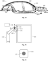
- Fig. 1a highlights a place 102 within the body 101, where one or more studs are to be fixed to the body 101 within the assembly line.
- Fig. 1a shows a vehicle coordinate system 104 which is positioned at a vehicle reference point 103.
- the vehicle reference point 103 may be the center of the front axis of the vehicle 100.
- the vehicle coordinate system 104 may comprise an x-axis (pointing from the front to the back of the vehicle 100), a y-axis (pointing from the left to the right of the vehicle 100) and a z-axis (pointing from the bottom to the top of the vehicle 100).
- Fig 1b shows an excerpt of an assembly line.
- Fig. 1b illustrates a rotating head system 110 which comprises a head 111 that may be rotated around a rotation point 121.
- the head 111 may be configured to fix, notably to weld, one or more studs 131 onto the body 101 of the vehicle 100.
- the pose of the head 111 may be indicated within a head coordinate system 124 having its origin at the rotation point 121.
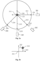
- Fig. 2a shows the head 111 and a plurality of sensors 201, 202, 203, 204, notably a plurality of cameras, which are placed at different angles 231, 232, 233, 234 and/or orientations 211, 212, 213, 214 around the head 111 (i.e. around the rotation point 121).
- Example angles 231, 232, 233, 234 and/or orientations 211, 212, 213, 214 are 90°, 135°, 180°, and 225° (possibly offset by ⁇ 90°).
- the head 111 may be turned sequentially to the different orientations 211, 212, 213, 214.
- K different (multi-dimensional) deviations between the actual position 212 and the target position 211 can be determined.
- the K different deviations may be combined into a deviation vector [ DEV ].
- the deviation vector [ DEV ] may be a 2 K ⁇ 1 vector which comprises the deviation components 221, 222 for the K different orientations 211, 212, 213, 214.
- the deviation vector [ DEV ] may be used to determine the actual pose of the head 111 and/or the rotation point 121 of the rotating head system 110 within the vehicle coordinate system 104. Notably an offset of the actual pose from a target pose may be determined. The actual pose or the offset can be taken into account during operation of the rotating head system 110, in order to enable the rotating head system 110 to operate in a precise and collision-free manner.
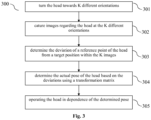
- the method 300 comprises capturing 302 K images using the K different cameras 201, 202, 203, 204, respectively.
- the K images may be captured sequentially as the head 111 is rotated into the K different orientations 211, 212, 213, 214, such that each image is indicative of the front face of the head 111. If the head 111 is positioned correctly with respect to the product 100, the front face of the head 111, notably a reference point 112 on the front face of the head 111, should be located at a target position 211 within each one of the K images. However, an offset of the actual pose of the head 111 (or rotation point 121) from the target pose of the head 111 (or rotation point 121) typically leads to a deviation of the reference point 112 from the target position 211 in at least one of the K images.
Landscapes
- Engineering & Computer Science (AREA)
- Robotics (AREA)
- Mechanical Engineering (AREA)
- Image Processing (AREA)
- Image Analysis (AREA)
Claims (10)
- Procédé (300) pour faire fonctionner un système de tête rotative (110), le système de tête rotative (110) comprenant une tête (111) qui est configurée pour être mise en rotation autour d'un point de rotation (121) ; le procédé (300) comprenant,- la mise en rotation (301) de la tête (111) autour du point de rotation (121) dans K orientations différentes (211, 212, 213, 214) de telle sorte qu'une face avant de la tête (111) fasse face à K caméras différentes (201, 202, 203, 204), respectivement, avec K > 3, qui sont agencées à K angles différents (231, 232, 233, 234) autour du point de rotation (121), respectivement ;- la capture (302) de K images à l'aide des K caméras différentes (201, 202, 203, 204), respectivement ;- la détermination (303) de K déviations du point de référence (112) sur la face avant de la tête (111) par rapport à la position cible (211) au sein des K images, respectivement ;- la détermination (304) d'un décalage d'une pose réelle de la tête (111) par rapport à la pose cible sur la base des K déviations à l'aide d'une matrice de transformation prédéterminée ; et- le fait de faire fonctionner (305) la tête (111) en fonction du décalage ;caractérisé par les étapes consistant à :- déterminer un vecteur de déviation indiquant les K déviations du point de référence (112) de la tête (111) par rapport à la position cible (211) ; et- multiplier le vecteur de déviation par la matrice de transformation pour déterminer un vecteur de décalage, le vecteur de décalage indiquant un décalage de translation et/ou un décalage de rotation d'une pose réelle de la tête (111) par rapport à la pose cible.
- Procédé (300) selon la revendication 1, dans lequel la matrice de transformation comprend une matrice jacobienne ou une estimation d'un inverse d'une matrice jacobienne.
- Procédé (300) selon l'une quelconque des revendications précédentes, dans lequel- la déviation du point de référence (112) de la tête (111) par rapport à la position cible (211) au sein d'une image particulière des K images comprend un premier composant de déviation (221) le long d'un premier axe de l'image donnée et un deuxième composant de déviation (222) le long d'un deuxième axe de l'image donnée ; et- le vecteur de déviation comprend en tant qu'éléments vectoriels les premiers composants de déviation (221) et les deuxièmes composants de déviation (222) pour les K déviations.
- Procédé selon la revendication 3, dans lequel- la matrice de transformation est un inverse d'une matrice jacobienne ; et- la matrice jacobienne comprend un vecteur de rangée pour chaque élément vectoriel du vecteur de déviation.
- Procédé selon la revendication 4, dans lequel- le vecteur de rangée de la matrice jacobienne pour le premier composant de déviation (221) le long du premier axe de l'image donnée comprend les éléments vectoriels

 -
- -
- - ° est l'opérateur de projection.
 - Procédé (300) selon l'une quelconque des revendications précédentes, dans lequel le fait de faire fonctionner (305) la tête (111) comprend le soudage d'un ou de plusieurs goujons (131) au produit (100) à l'aide de la tête (111) du système de tête rotative (110).
- Procédé (300) selon l'une quelconque des revendications précédentes, dans lequel- la tête (111) comprend un dispositif de saisie pour saisir un goujon (131) ; et- le point de référence (112) est situé sur le dispositif de saisie.
- Procédé (300) selon l'une quelconque des revendications précédentes, dans lequel les K angles différents s'étendent sur une plage angulaire de 45° ou plus.
- Procédé (300) selon l'une quelconque des revendications précédentes, dans lequel la matrice de transformation comprend une matrice jacobienne ou une estimation d'un inverse d'une matrice jacobienne, la matrice jacobienne dépendant uniquement des K orientations différentes (211, 212, 213, 214) et des positions des K caméras différentes (201, 202, 203, 204) .
- Système pour faire fonctionner un système de tête rotative (110), le système comprenant :- un système de tête rotative (110) qui comprend une tête (111) qui peut être mise en rotation autour d'un point de rotation (121) et qui est configurée pour fixer une partie (131) sur un corps (101) d'un produit (100) à l'aide de la tête (111),- K caméras différentes (201, 202, 203, 204), avec K > 3, qui sont agencées à K angles différents (231, 232, 233, 234) autour du point de rotation (121), respectivement, et- une unité de commande (150) pour commander le système de tête rotative (110), l'unité de commande (150) étant configurée pour mettre en œuvre le procédé selon la revendication 1.
Priority Applications (1)
| Application Number | Priority Date | Filing Date | Title |
|---|---|---|---|
| EP19196855.1A EP3792012B1 (fr) | 2019-09-12 | 2019-09-12 | Procédé et unité de commande pour faire fonctionner un système de tête rotative avec plusieurs caméras |
Applications Claiming Priority (1)
| Application Number | Priority Date | Filing Date | Title |
|---|---|---|---|
| EP19196855.1A EP3792012B1 (fr) | 2019-09-12 | 2019-09-12 | Procédé et unité de commande pour faire fonctionner un système de tête rotative avec plusieurs caméras |
Publications (2)
| Publication Number | Publication Date |
|---|---|
| EP3792012A1 EP3792012A1 (fr) | 2021-03-17 |
| EP3792012B1 true EP3792012B1 (fr) | 2023-12-27 |
Family
ID=67997334
Family Applications (1)
| Application Number | Title | Priority Date | Filing Date |
|---|---|---|---|
| EP19196855.1A Active EP3792012B1 (fr) | 2019-09-12 | 2019-09-12 | Procédé et unité de commande pour faire fonctionner un système de tête rotative avec plusieurs caméras |
Country Status (1)
| Country | Link |
|---|---|
| EP (1) | EP3792012B1 (fr) |
Families Citing this family (1)
| Publication number | Priority date | Publication date | Assignee | Title |
|---|---|---|---|---|
| EP4079463A1 (fr) * | 2021-04-20 | 2022-10-26 | Bayerische Motoren Werke Aktiengesellschaft | Procédé et unité de commande pour calibrer un système de tête rotative |
Family Cites Families (4)
| Publication number | Priority date | Publication date | Assignee | Title |
|---|---|---|---|---|
| ATE531488T1 (de) * | 2002-03-04 | 2011-11-15 | Vmt Vision Machine Technic Bildverarbeitungssysteme Gmbh | Verfahren zur bestimmung der lage eines objektes und eines werkstücks im raum zur automatischen montage des werkstücks am objekt |
| DE102004026814A1 (de) * | 2004-06-02 | 2005-12-29 | Kuka Roboter Gmbh | Verfahren und Vorrichtung zum Verbessern der Positioniergenauigkeit eines Handhabungsgeräts |
| US9393694B2 (en) * | 2010-05-14 | 2016-07-19 | Cognex Corporation | System and method for robust calibration between a machine vision system and a robot |
| US11161248B2 (en) * | 2015-09-29 | 2021-11-02 | Koninklijke Philips N.V. | Automatic robotic arm calibration to camera system using a laser |
-
2019
- 2019-09-12 EP EP19196855.1A patent/EP3792012B1/fr active Active
Also Published As
| Publication number | Publication date |
|---|---|
| EP3792012A1 (fr) | 2021-03-17 |
Similar Documents
| Publication | Publication Date | Title |
|---|---|---|
| EP1607194B1 (fr) | Système robotisé comprenant plusieurs robots munis de moyens pour calibrer leur position relative | |
| US10618166B2 (en) | Teaching position correction device and teaching position correction method | |
| EP3088843B1 (fr) | Système et procédé d'alignement d'une trame de référence de machine à mouvement coordonné avec un cadre de référence d'un système de mesure | |
| CN102909728B (zh) | 机器人工具中心点的视觉校正方法 | |
| JP3733364B2 (ja) | 教示位置修正方法 | |
| US8918210B2 (en) | Method of detecting an inter-axis offset of 6-axis robot | |
| US7532949B2 (en) | Measuring system | |
| EP1043126B1 (fr) | Procédé de génération de modèle d'apprentissage | |
| EP3366433A1 (fr) | Procédé de commande d'un robot, procédé d'apprentissage d'un robot et système de robot | |
| JP4267005B2 (ja) | 計測装置及びキャリブレーション方法 | |
| US9517560B2 (en) | Robot system and calibration method of the robot system | |
| US20110029131A1 (en) | Apparatus and method for measuring tool center point position of robot | |
| US20180065204A1 (en) | Welding process | |
| US20110208356A1 (en) | Robot having learning control function | |
| JP6912529B2 (ja) | 視覚誘導ロボットアームの補正方法 | |
| US20170072562A1 (en) | Deflection measurement system for measuring deflection of articulated robot | |
| US20210065356A1 (en) | Apparatus and method for heat exchanger inspection | |
| US20200262080A1 (en) | Comprehensive model-based method for gantry robot calibration via a dual camera vision system | |
| EP4101604A1 (fr) | Système et procédé d'amélioration de la précision de la coordination il-main 3d d'un système robotique | |
| EP2070664A1 (fr) | Système de traitement d'objets | |
| EP3792012A1 (fr) | Procédé et unité de commande pour faire fonctionner un système de tête rotative avec plusieurs caméras | |
| EP3620270B1 (fr) | Procédé et unité de commande pour commander un robot d'assemblage | |
| KR102738516B1 (ko) | 실링 로봇 티칭 시스템 및 그 방법 | |
| EP4079463A1 (fr) | Procédé et unité de commande pour calibrer un système de tête rotative | |
| US12623354B2 (en) | Positioning method and positioning device |
Legal Events
| Date | Code | Title | Description |
|---|---|---|---|
| PUAI | Public reference made under article 153(3) epc to a published international application that has entered the european phase |
Free format text: ORIGINAL CODE: 0009012 |
|
| STAA | Information on the status of an ep patent application or granted ep patent |
Free format text: STATUS: THE APPLICATION HAS BEEN PUBLISHED |
|
| AK | Designated contracting states |
Kind code of ref document: A1 Designated state(s): AL AT BE BG CH CY CZ DE DK EE ES FI FR GB GR HR HU IE IS IT LI LT LU LV MC MK MT NL NO PL PT RO RS SE SI SK SM TR |
|
| AX | Request for extension of the european patent |
Extension state: BA ME |
|
| STAA | Information on the status of an ep patent application or granted ep patent |
Free format text: STATUS: REQUEST FOR EXAMINATION WAS MADE |
|
| 17P | Request for examination filed |
Effective date: 20210331 |
|
| RBV | Designated contracting states (corrected) |
Designated state(s): AL AT BE BG CH CY CZ DE DK EE ES FI FR GB GR HR HU IE IS IT LI LT LU LV MC MK MT NL NO PL PT RO RS SE SI SK SM TR |
|
| STAA | Information on the status of an ep patent application or granted ep patent |
Free format text: STATUS: EXAMINATION IS IN PROGRESS |
|
| 17Q | First examination report despatched |
Effective date: 20220419 |
|
| P01 | Opt-out of the competence of the unified patent court (upc) registered |
Effective date: 20230503 |
|
| GRAP | Despatch of communication of intention to grant a patent |
Free format text: ORIGINAL CODE: EPIDOSNIGR1 |
|
| STAA | Information on the status of an ep patent application or granted ep patent |
Free format text: STATUS: GRANT OF PATENT IS INTENDED |
|
| INTG | Intention to grant announced |
Effective date: 20230914 |
|
| GRAS | Grant fee paid |
Free format text: ORIGINAL CODE: EPIDOSNIGR3 |
|
| GRAA | (expected) grant |
Free format text: ORIGINAL CODE: 0009210 |
|
| STAA | Information on the status of an ep patent application or granted ep patent |
Free format text: STATUS: THE PATENT HAS BEEN GRANTED |
|
| AK | Designated contracting states |
Kind code of ref document: B1 Designated state(s): AL AT BE BG CH CY CZ DE DK EE ES FI FR GB GR HR HU IE IS IT LI LT LU LV MC MK MT NL NO PL PT RO RS SE SI SK SM TR |
|
| REG | Reference to a national code |
Ref country code: GB Ref legal event code: FG4D |
|
| REG | Reference to a national code |
Ref country code: CH Ref legal event code: EP |
|
| REG | Reference to a national code |
Ref country code: DE Ref legal event code: R096 Ref document number: 602019043896 Country of ref document: DE |
|
| REG | Reference to a national code |
Ref country code: IE Ref legal event code: FG4D |
|
| PG25 | Lapsed in a contracting state [announced via postgrant information from national office to epo] |
Ref country code: GR Free format text: LAPSE BECAUSE OF FAILURE TO SUBMIT A TRANSLATION OF THE DESCRIPTION OR TO PAY THE FEE WITHIN THE PRESCRIBED TIME-LIMIT Effective date: 20240328 |
|
| REG | Reference to a national code |
Ref country code: LT Ref legal event code: MG9D |
|
| PG25 | Lapsed in a contracting state [announced via postgrant information from national office to epo] |
Ref country code: LT Free format text: LAPSE BECAUSE OF FAILURE TO SUBMIT A TRANSLATION OF THE DESCRIPTION OR TO PAY THE FEE WITHIN THE PRESCRIBED TIME-LIMIT Effective date: 20231227 |
|
| PG25 | Lapsed in a contracting state [announced via postgrant information from national office to epo] |
Ref country code: ES Free format text: LAPSE BECAUSE OF FAILURE TO SUBMIT A TRANSLATION OF THE DESCRIPTION OR TO PAY THE FEE WITHIN THE PRESCRIBED TIME-LIMIT Effective date: 20231227 |
|
| PG25 | Lapsed in a contracting state [announced via postgrant information from national office to epo] |
Ref country code: LT Free format text: LAPSE BECAUSE OF FAILURE TO SUBMIT A TRANSLATION OF THE DESCRIPTION OR TO PAY THE FEE WITHIN THE PRESCRIBED TIME-LIMIT Effective date: 20231227 Ref country code: GR Free format text: LAPSE BECAUSE OF FAILURE TO SUBMIT A TRANSLATION OF THE DESCRIPTION OR TO PAY THE FEE WITHIN THE PRESCRIBED TIME-LIMIT Effective date: 20240328 Ref country code: FI Free format text: LAPSE BECAUSE OF FAILURE TO SUBMIT A TRANSLATION OF THE DESCRIPTION OR TO PAY THE FEE WITHIN THE PRESCRIBED TIME-LIMIT Effective date: 20231227 Ref country code: ES Free format text: LAPSE BECAUSE OF FAILURE TO SUBMIT A TRANSLATION OF THE DESCRIPTION OR TO PAY THE FEE WITHIN THE PRESCRIBED TIME-LIMIT Effective date: 20231227 Ref country code: BG Free format text: LAPSE BECAUSE OF FAILURE TO SUBMIT A TRANSLATION OF THE DESCRIPTION OR TO PAY THE FEE WITHIN THE PRESCRIBED TIME-LIMIT Effective date: 20240327 |
|
| REG | Reference to a national code |
Ref country code: NL Ref legal event code: MP Effective date: 20231227 |
|
| REG | Reference to a national code |
Ref country code: AT Ref legal event code: MK05 Ref document number: 1644102 Country of ref document: AT Kind code of ref document: T Effective date: 20231227 |
|
| PG25 | Lapsed in a contracting state [announced via postgrant information from national office to epo] |
Ref country code: NL Free format text: LAPSE BECAUSE OF FAILURE TO SUBMIT A TRANSLATION OF THE DESCRIPTION OR TO PAY THE FEE WITHIN THE PRESCRIBED TIME-LIMIT Effective date: 20231227 |
|
| PG25 | Lapsed in a contracting state [announced via postgrant information from national office to epo] |
Ref country code: SE Free format text: LAPSE BECAUSE OF FAILURE TO SUBMIT A TRANSLATION OF THE DESCRIPTION OR TO PAY THE FEE WITHIN THE PRESCRIBED TIME-LIMIT Effective date: 20231227 Ref country code: RS Free format text: LAPSE BECAUSE OF FAILURE TO SUBMIT A TRANSLATION OF THE DESCRIPTION OR TO PAY THE FEE WITHIN THE PRESCRIBED TIME-LIMIT Effective date: 20231227 Ref country code: NO Free format text: LAPSE BECAUSE OF FAILURE TO SUBMIT A TRANSLATION OF THE DESCRIPTION OR TO PAY THE FEE WITHIN THE PRESCRIBED TIME-LIMIT Effective date: 20240327 Ref country code: NL Free format text: LAPSE BECAUSE OF FAILURE TO SUBMIT A TRANSLATION OF THE DESCRIPTION OR TO PAY THE FEE WITHIN THE PRESCRIBED TIME-LIMIT Effective date: 20231227 Ref country code: LV Free format text: LAPSE BECAUSE OF FAILURE TO SUBMIT A TRANSLATION OF THE DESCRIPTION OR TO PAY THE FEE WITHIN THE PRESCRIBED TIME-LIMIT Effective date: 20231227 Ref country code: HR Free format text: LAPSE BECAUSE OF FAILURE TO SUBMIT A TRANSLATION OF THE DESCRIPTION OR TO PAY THE FEE WITHIN THE PRESCRIBED TIME-LIMIT Effective date: 20231227 |
|
| PG25 | Lapsed in a contracting state [announced via postgrant information from national office to epo] |
Ref country code: IS Free format text: LAPSE BECAUSE OF FAILURE TO SUBMIT A TRANSLATION OF THE DESCRIPTION OR TO PAY THE FEE WITHIN THE PRESCRIBED TIME-LIMIT Effective date: 20240427 |
|
| PG25 | Lapsed in a contracting state [announced via postgrant information from national office to epo] |
Ref country code: CZ Free format text: LAPSE BECAUSE OF FAILURE TO SUBMIT A TRANSLATION OF THE DESCRIPTION OR TO PAY THE FEE WITHIN THE PRESCRIBED TIME-LIMIT Effective date: 20231227 Ref country code: AT Free format text: LAPSE BECAUSE OF FAILURE TO SUBMIT A TRANSLATION OF THE DESCRIPTION OR TO PAY THE FEE WITHIN THE PRESCRIBED TIME-LIMIT Effective date: 20231227 |
|
| PG25 | Lapsed in a contracting state [announced via postgrant information from national office to epo] |
Ref country code: SK Free format text: LAPSE BECAUSE OF FAILURE TO SUBMIT A TRANSLATION OF THE DESCRIPTION OR TO PAY THE FEE WITHIN THE PRESCRIBED TIME-LIMIT Effective date: 20231227 |
|
| PG25 | Lapsed in a contracting state [announced via postgrant information from national office to epo] |
Ref country code: SM Free format text: LAPSE BECAUSE OF FAILURE TO SUBMIT A TRANSLATION OF THE DESCRIPTION OR TO PAY THE FEE WITHIN THE PRESCRIBED TIME-LIMIT Effective date: 20231227 Ref country code: SK Free format text: LAPSE BECAUSE OF FAILURE TO SUBMIT A TRANSLATION OF THE DESCRIPTION OR TO PAY THE FEE WITHIN THE PRESCRIBED TIME-LIMIT Effective date: 20231227 Ref country code: RO Free format text: LAPSE BECAUSE OF FAILURE TO SUBMIT A TRANSLATION OF THE DESCRIPTION OR TO PAY THE FEE WITHIN THE PRESCRIBED TIME-LIMIT Effective date: 20231227 Ref country code: IT Free format text: LAPSE BECAUSE OF FAILURE TO SUBMIT A TRANSLATION OF THE DESCRIPTION OR TO PAY THE FEE WITHIN THE PRESCRIBED TIME-LIMIT Effective date: 20231227 Ref country code: IS Free format text: LAPSE BECAUSE OF FAILURE TO SUBMIT A TRANSLATION OF THE DESCRIPTION OR TO PAY THE FEE WITHIN THE PRESCRIBED TIME-LIMIT Effective date: 20240427 Ref country code: EE Free format text: LAPSE BECAUSE OF FAILURE TO SUBMIT A TRANSLATION OF THE DESCRIPTION OR TO PAY THE FEE WITHIN THE PRESCRIBED TIME-LIMIT Effective date: 20231227 Ref country code: CZ Free format text: LAPSE BECAUSE OF FAILURE TO SUBMIT A TRANSLATION OF THE DESCRIPTION OR TO PAY THE FEE WITHIN THE PRESCRIBED TIME-LIMIT Effective date: 20231227 Ref country code: AT Free format text: LAPSE BECAUSE OF FAILURE TO SUBMIT A TRANSLATION OF THE DESCRIPTION OR TO PAY THE FEE WITHIN THE PRESCRIBED TIME-LIMIT Effective date: 20231227 |
|
| PG25 | Lapsed in a contracting state [announced via postgrant information from national office to epo] |
Ref country code: PL Free format text: LAPSE BECAUSE OF FAILURE TO SUBMIT A TRANSLATION OF THE DESCRIPTION OR TO PAY THE FEE WITHIN THE PRESCRIBED TIME-LIMIT Effective date: 20231227 Ref country code: PT Free format text: LAPSE BECAUSE OF FAILURE TO SUBMIT A TRANSLATION OF THE DESCRIPTION OR TO PAY THE FEE WITHIN THE PRESCRIBED TIME-LIMIT Effective date: 20240429 |
|
| PG25 | Lapsed in a contracting state [announced via postgrant information from national office to epo] |
Ref country code: PT Free format text: LAPSE BECAUSE OF FAILURE TO SUBMIT A TRANSLATION OF THE DESCRIPTION OR TO PAY THE FEE WITHIN THE PRESCRIBED TIME-LIMIT Effective date: 20240429 Ref country code: PL Free format text: LAPSE BECAUSE OF FAILURE TO SUBMIT A TRANSLATION OF THE DESCRIPTION OR TO PAY THE FEE WITHIN THE PRESCRIBED TIME-LIMIT Effective date: 20231227 |
|
| REG | Reference to a national code |
Ref country code: DE Ref legal event code: R097 Ref document number: 602019043896 Country of ref document: DE |
|
| PG25 | Lapsed in a contracting state [announced via postgrant information from national office to epo] |
Ref country code: DK Free format text: LAPSE BECAUSE OF FAILURE TO SUBMIT A TRANSLATION OF THE DESCRIPTION OR TO PAY THE FEE WITHIN THE PRESCRIBED TIME-LIMIT Effective date: 20231227 |
|
| PG25 | Lapsed in a contracting state [announced via postgrant information from national office to epo] |
Ref country code: DK Free format text: LAPSE BECAUSE OF FAILURE TO SUBMIT A TRANSLATION OF THE DESCRIPTION OR TO PAY THE FEE WITHIN THE PRESCRIBED TIME-LIMIT Effective date: 20231227 |
|
| PLBE | No opposition filed within time limit |
Free format text: ORIGINAL CODE: 0009261 |
|
| STAA | Information on the status of an ep patent application or granted ep patent |
Free format text: STATUS: NO OPPOSITION FILED WITHIN TIME LIMIT |
|
| 26N | No opposition filed |
Effective date: 20240930 |
|
| PG25 | Lapsed in a contracting state [announced via postgrant information from national office to epo] |
Ref country code: SI Free format text: LAPSE BECAUSE OF FAILURE TO SUBMIT A TRANSLATION OF THE DESCRIPTION OR TO PAY THE FEE WITHIN THE PRESCRIBED TIME-LIMIT Effective date: 20231227 Ref country code: MC Free format text: LAPSE BECAUSE OF FAILURE TO SUBMIT A TRANSLATION OF THE DESCRIPTION OR TO PAY THE FEE WITHIN THE PRESCRIBED TIME-LIMIT Effective date: 20231227 |
|
| REG | Reference to a national code |
Ref country code: CH Ref legal event code: PL |
|
| PG25 | Lapsed in a contracting state [announced via postgrant information from national office to epo] |
Ref country code: LU Free format text: LAPSE BECAUSE OF NON-PAYMENT OF DUE FEES Effective date: 20240912 |
|
| REG | Reference to a national code |
Ref country code: BE Ref legal event code: MM Effective date: 20240930 |
|
| PG25 | Lapsed in a contracting state [announced via postgrant information from national office to epo] |
Ref country code: BE Free format text: LAPSE BECAUSE OF NON-PAYMENT OF DUE FEES Effective date: 20240930 |
|
| PG25 | Lapsed in a contracting state [announced via postgrant information from national office to epo] |
Ref country code: CH Free format text: LAPSE BECAUSE OF NON-PAYMENT OF DUE FEES Effective date: 20240930 |
|
| PG25 | Lapsed in a contracting state [announced via postgrant information from national office to epo] |
Ref country code: IE Free format text: LAPSE BECAUSE OF NON-PAYMENT OF DUE FEES Effective date: 20240912 |
|
| PGFP | Annual fee paid to national office [announced via postgrant information from national office to epo] |
Ref country code: DE Payment date: 20250909 Year of fee payment: 7 |
|
| PGFP | Annual fee paid to national office [announced via postgrant information from national office to epo] |
Ref country code: GB Payment date: 20250923 Year of fee payment: 7 |
|
| PGFP | Annual fee paid to national office [announced via postgrant information from national office to epo] |
Ref country code: FR Payment date: 20250924 Year of fee payment: 7 |
|
| PG25 | Lapsed in a contracting state [announced via postgrant information from national office to epo] |
Ref country code: CY Free format text: LAPSE BECAUSE OF FAILURE TO SUBMIT A TRANSLATION OF THE DESCRIPTION OR TO PAY THE FEE WITHIN THE PRESCRIBED TIME-LIMIT; INVALID AB INITIO Effective date: 20190912 |
|
| PG25 | Lapsed in a contracting state [announced via postgrant information from national office to epo] |
Ref country code: HU Free format text: LAPSE BECAUSE OF FAILURE TO SUBMIT A TRANSLATION OF THE DESCRIPTION OR TO PAY THE FEE WITHIN THE PRESCRIBED TIME-LIMIT; INVALID AB INITIO Effective date: 20190912 |