EP3792028A1 - Vorrichtung und verfahren zur wiederverwertung - Google Patents
Vorrichtung und verfahren zur wiederverwertung Download PDFInfo
- Publication number
- EP3792028A1 EP3792028A1 EP20275137.6A EP20275137A EP3792028A1 EP 3792028 A1 EP3792028 A1 EP 3792028A1 EP 20275137 A EP20275137 A EP 20275137A EP 3792028 A1 EP3792028 A1 EP 3792028A1
- Authority
- EP
- European Patent Office
- Prior art keywords
- section
- conveying
- beating
- conveying section
- artificial
- Prior art date
- Legal status (The legal status is an assumption and is not a legal conclusion. Google has not performed a legal analysis and makes no representation as to the accuracy of the status listed.)
- Withdrawn
Links
- 238000004064 recycling Methods 0.000 title claims abstract description 23
- 238000000034 method Methods 0.000 title claims description 23
- 239000000463 material Substances 0.000 claims abstract description 102
- 238000010009 beating Methods 0.000 claims abstract description 48
- 239000007788 liquid Substances 0.000 claims description 28
- XLYOFNOQVPJJNP-UHFFFAOYSA-N water Substances O XLYOFNOQVPJJNP-UHFFFAOYSA-N 0.000 claims description 10
- 244000025254 Cannabis sativa Species 0.000 description 41
- 239000004576 sand Substances 0.000 description 18
- 229920001971 elastomer Polymers 0.000 description 15
- 239000005060 rubber Substances 0.000 description 15
- 239000000835 fiber Substances 0.000 description 8
- 239000004033 plastic Substances 0.000 description 6
- 229920003023 plastic Polymers 0.000 description 6
- -1 polypropylene Polymers 0.000 description 6
- 239000004698 Polyethylene Substances 0.000 description 5
- 239000004743 Polypropylene Substances 0.000 description 5
- 229920000573 polyethylene Polymers 0.000 description 5
- 229920001155 polypropylene Polymers 0.000 description 5
- 238000009434 installation Methods 0.000 description 4
- 239000004677 Nylon Substances 0.000 description 2
- 239000000701 coagulant Substances 0.000 description 2
- 239000000645 desinfectant Substances 0.000 description 2
- 230000000694 effects Effects 0.000 description 2
- 239000000203 mixture Substances 0.000 description 2
- 229920001778 nylon Polymers 0.000 description 2
- 230000000284 resting effect Effects 0.000 description 2
- 238000005096 rolling process Methods 0.000 description 2
- 239000000243 solution Substances 0.000 description 2
- 238000003860 storage Methods 0.000 description 2
- 244000060011 Cocos nucifera Species 0.000 description 1
- 235000013162 Cocos nucifera Nutrition 0.000 description 1
- 239000012615 aggregate Substances 0.000 description 1
- 230000009286 beneficial effect Effects 0.000 description 1
- 230000015556 catabolic process Effects 0.000 description 1
- 238000004140 cleaning Methods 0.000 description 1
- 239000007799 cork Substances 0.000 description 1
- 238000006731 degradation reaction Methods 0.000 description 1
- 239000003292 glue Substances 0.000 description 1
- 230000005484 gravity Effects 0.000 description 1
- 238000011065 in-situ storage Methods 0.000 description 1
- 238000002347 injection Methods 0.000 description 1
- 239000007924 injection Substances 0.000 description 1
- 229920000126 latex Polymers 0.000 description 1
- 239000004816 latex Substances 0.000 description 1
- 239000010410 layer Substances 0.000 description 1
- 238000012423 maintenance Methods 0.000 description 1
- 229920002635 polyurethane Polymers 0.000 description 1
- 239000004814 polyurethane Substances 0.000 description 1
- 238000004826 seaming Methods 0.000 description 1
- 230000035939 shock Effects 0.000 description 1
- 239000002904 solvent Substances 0.000 description 1
- 239000000126 substance Substances 0.000 description 1
- 239000003643 water by type Substances 0.000 description 1
Images
Classifications
-
- B—PERFORMING OPERATIONS; TRANSPORTING
- B29—WORKING OF PLASTICS; WORKING OF SUBSTANCES IN A PLASTIC STATE IN GENERAL
- B29B—PREPARATION OR PRETREATMENT OF THE MATERIAL TO BE SHAPED; MAKING GRANULES OR PREFORMS; RECOVERY OF PLASTICS OR OTHER CONSTITUENTS OF WASTE MATERIAL CONTAINING PLASTICS
- B29B17/00—Recovery of plastics or other constituents of waste material containing plastics
- B29B17/02—Separating plastics from other materials
-
- B—PERFORMING OPERATIONS; TRANSPORTING
- B08—CLEANING
- B08B—CLEANING IN GENERAL; PREVENTION OF FOULING IN GENERAL
- B08B1/00—Cleaning by methods involving the use of tools
- B08B1/10—Cleaning by methods involving the use of tools characterised by the type of cleaning tool
-
- B—PERFORMING OPERATIONS; TRANSPORTING
- B08—CLEANING
- B08B—CLEANING IN GENERAL; PREVENTION OF FOULING IN GENERAL
- B08B1/00—Cleaning by methods involving the use of tools
- B08B1/20—Cleaning of moving articles, e.g. of moving webs or of objects on a conveyor
-
- B—PERFORMING OPERATIONS; TRANSPORTING
- B08—CLEANING
- B08B—CLEANING IN GENERAL; PREVENTION OF FOULING IN GENERAL
- B08B3/00—Cleaning by methods involving the use or presence of liquid or steam
- B08B3/04—Cleaning involving contact with liquid
- B08B3/041—Cleaning travelling work
- B08B3/042—Cleaning travelling work the loose articles or bulk material travelling gradually through a drum or other container, e.g. by helix or gravity
-
- B—PERFORMING OPERATIONS; TRANSPORTING
- B08—CLEANING
- B08B—CLEANING IN GENERAL; PREVENTION OF FOULING IN GENERAL
- B08B3/00—Cleaning by methods involving the use or presence of liquid or steam
- B08B3/04—Cleaning involving contact with liquid
- B08B3/08—Cleaning involving contact with liquid the liquid having chemical or dissolving effect
-
- B—PERFORMING OPERATIONS; TRANSPORTING
- B08—CLEANING
- B08B—CLEANING IN GENERAL; PREVENTION OF FOULING IN GENERAL
- B08B7/00—Cleaning by methods not provided for in a single other subclass or a single group in this subclass
- B08B7/02—Cleaning by methods not provided for in a single other subclass or a single group in this subclass by distortion, beating, or vibration of the surface to be cleaned
-
- B—PERFORMING OPERATIONS; TRANSPORTING
- B08—CLEANING
- B08B—CLEANING IN GENERAL; PREVENTION OF FOULING IN GENERAL
- B08B7/00—Cleaning by methods not provided for in a single other subclass or a single group in this subclass
- B08B7/04—Cleaning by methods not provided for in a single other subclass or a single group in this subclass by a combination of operations
-
- B—PERFORMING OPERATIONS; TRANSPORTING
- B65—CONVEYING; PACKING; STORING; HANDLING THIN OR FILAMENTARY MATERIAL
- B65H—HANDLING THIN OR FILAMENTARY MATERIAL, e.g. SHEETS, WEBS, CABLES
- B65H18/00—Winding webs
- B65H18/08—Web-winding mechanisms
- B65H18/14—Mechanisms in which power is applied to web roll, e.g. to effect continuous advancement of web
- B65H18/145—Reel-to-reel type web winding and unwinding mechanisms
-
- B—PERFORMING OPERATIONS; TRANSPORTING
- B29—WORKING OF PLASTICS; WORKING OF SUBSTANCES IN A PLASTIC STATE IN GENERAL
- B29B—PREPARATION OR PRETREATMENT OF THE MATERIAL TO BE SHAPED; MAKING GRANULES OR PREFORMS; RECOVERY OF PLASTICS OR OTHER CONSTITUENTS OF WASTE MATERIAL CONTAINING PLASTICS
- B29B17/00—Recovery of plastics or other constituents of waste material containing plastics
- B29B17/02—Separating plastics from other materials
- B29B2017/0213—Specific separating techniques
- B29B2017/0217—Mechanical separating techniques; devices therefor
- B29B2017/0227—Vibratory or shaking tables
-
- B—PERFORMING OPERATIONS; TRANSPORTING
- B29—WORKING OF PLASTICS; WORKING OF SUBSTANCES IN A PLASTIC STATE IN GENERAL
- B29L—INDEXING SCHEME ASSOCIATED WITH SUBCLASS B29C, RELATING TO PARTICULAR ARTICLES
- B29L2031/00—Other particular articles
- B29L2031/732—Floor coverings
-
- B—PERFORMING OPERATIONS; TRANSPORTING
- B65—CONVEYING; PACKING; STORING; HANDLING THIN OR FILAMENTARY MATERIAL
- B65H—HANDLING THIN OR FILAMENTARY MATERIAL, e.g. SHEETS, WEBS, CABLES
- B65H2406/00—Means using fluid
- B65H2406/20—Means using fluid made only for liquid medium
-
- B—PERFORMING OPERATIONS; TRANSPORTING
- B65—CONVEYING; PACKING; STORING; HANDLING THIN OR FILAMENTARY MATERIAL
- B65H—HANDLING THIN OR FILAMENTARY MATERIAL, e.g. SHEETS, WEBS, CABLES
- B65H2515/00—Physical entities not provided for in groups B65H2511/00 or B65H2513/00
- B65H2515/84—Quality; Condition, e.g. degree of wear
-
- Y—GENERAL TAGGING OF NEW TECHNOLOGICAL DEVELOPMENTS; GENERAL TAGGING OF CROSS-SECTIONAL TECHNOLOGIES SPANNING OVER SEVERAL SECTIONS OF THE IPC; TECHNICAL SUBJECTS COVERED BY FORMER USPC CROSS-REFERENCE ART COLLECTIONS [XRACs] AND DIGESTS
- Y02—TECHNOLOGIES OR APPLICATIONS FOR MITIGATION OR ADAPTATION AGAINST CLIMATE CHANGE
- Y02W—CLIMATE CHANGE MITIGATION TECHNOLOGIES RELATED TO WASTEWATER TREATMENT OR WASTE MANAGEMENT
- Y02W30/00—Technologies for solid waste management
- Y02W30/50—Reuse, recycling or recovery technologies
- Y02W30/62—Plastics recycling; Rubber recycling
Definitions
- the invention to which this application relates is an apparatus and method for recycling.
- the following description refers to an apparatus and process for recycling artificial or synthetic grass.
- the apparatus and process of the present invention may also be used for recycling other synthetic products.
- Astroturf also known as artificial or synthetic grass (AG) comes in many forms and has many different uses. It is generally used in areas where grass cannot grow, or in areas where grass maintenance is impossible, difficult, or undesired. AG is used mainly in sports stadiums and arenas but can also be found on playgrounds and in other spaces, even in domestic properties as a garden turf replacement.
- the main components of AG comprise up to seven different layers: fibres; infill; backing; seaming; turf lock; shock pad; and base layer.
- the layers can be built up in different materials and combinations of materials in order to achieve different properties required for different sports and activities.
- the lifespan of an AG installation in a garden, sports field, stadium or other will be between 10-15 years, at which point it will need to be replaced.
- the old AG installation consequently is removed but many of the materials can be reused or recycled and, as such, it will be taken for processing and recycling.
- a consequence of all the various materials mentioned above forming all these layers, plastics, sand, rubber, aggregates glues, tapes etc. is that the recycling process has to cope with all these materials and the degradation each has encountered over the 10-15 years it has been in situ. Furthermore, the recycling process also has to remove from these materials all dirt and rubbish deposited upon it over those years.
- While most artificial grass is made of plastic materials, including polypropylene, polyethylene, latex and polyurethane, which can all easily be recycled, it also contains infill.
- the materials that are used for infill, such as sand, are difficult to separate from the recyclable components of artificial grass.
- the issue of recycling lies in separating all of the materials that are used to create synthetic turf so that they can be recycled properly. For that reason, it was much easier - and less expensive - to simply toss fake grass into a landfill. In fact, this is likely why so many people believed, for so long, that this landscaping material could not be recycled.
- the vacuuming process is also quite labour intensive and time consuming and requires the separate transportation of the sand/rubber mix afterwards. Furthermore, it is often the case that the plastics, whilst being adequately separated from other products like the sand and rubber, are not separated one plastic from the other. This usually results in all the plastics being classed as low grade and where re-use of the plastics does occur, it is in low-grade products such as drainage pipes.
- an apparatus for recycling artificial or synthetic layered materials including:
- said artificial or synthetic layered material is an artificial or synthetic grass (AG).
- said material includes a top layer, said top layer comprising a fibre layer having a plurality of blades of artificial or synthetic grass.
- said fibre layer may be formed from nylon, polypropylene (PPE) or polyethylene (PE).
- infill materials may be dispersed within the fibre layer and between blades of artificial or synthetic grass. Such infill materials may include any or any combination of organic coconut fibres and cork; pea gravel and rubber; and/or sand and rubber.
- said first conveying section includes one or more conveying members, provided to unroll and pass said material along the apparatus, in use.
- said first conveying section is arranged to present said material, in use, to said beating section in an inverted manner. That is to say, a top side or layer of said material is arranged to face down, and an underside of said material is arranged to face upwardly, in use.
- said beating section includes at least a first beating member.
- said first conveying section is arranged to unroll and expose/present an underside of said material to said beating member, in use.
- said beating member is arranged to beat and/or agitate an underside of said material to dislodge, expel and/or remove debris, infill and other such particulates from a top side or layer of the material, in use.
- said beating member may be provided as an elongate member, having a longitudinal axis substantially perpendicular to the path of the material being moved from the first conveying section to the second conveying section, in use.
- said beating member may be provided having a substantially, square, rectangular, triangular or other such profile in cross-section.
- said beating member may be rotatable and/or pivotable and/or may be arranged to oscillate about a longitudinal axis thereof.
- corners and or edges of said beating member may be arranged to impact, grind, slide and/or move along or on an underside of the material, in use. Such movement is provided to aid in "fanning out” blades and/or fibres provided on the top side or layer of the material, thereby loosening and/or removing debris, infill etc. located therebetween.
- said beating member may be movable in substantially vertical and/or horizontal directions, or in curved paths, so as to impact said material in different manners, in use.
- the speed of movement, rotation, pivoting, and/or oscillating of the beating member may be varied by a user, in use.
- two or more beating members may be provided in said beating section.
- said beating section may include a plurality of beating members, wherein said beating members may be provided as hammer or mallet members.
- said beating section may further include a liquid inlet portion.
- said liquid inlet portion is arranged to permit the inlet and flow of liquid across, over and/or around said material, in use.
- said liquid inlet portion is arranged to provide a flow of liquid substantially perpendicular to the path of the material being moved from the first conveying section to the second conveying section, in use.
- a liquid inlet portion serves to wash / rinse and remove debris, infill and other such particulates from the material, in use. When dry, the debris or particulates may still hang in the air surrounding the material and thus may not fully be dislodged or removed therefrom; the provision of a means to inject liquid on and across the material aids in trapping the particulates and washes / rinses them away from the material.
- liquid outlet means is provided for the outflow of liquid and debris/particulates trapped or contained therein.
- the liquid containing the debris and particulates may subsequently be processed to separate the materials contained therein for subsequent recycling and/or reuse.
- said liquid may be water.
- said liquid may further include other solvents/solutions or materials therein.
- said solutions or materials may include disinfectants and/or coagulants. These may be provided to aid in the removal of debris and particulates from the material and also to clean and disinfect the material.
- said second conveying section includes one or more conveying members, provided to receive and re-roll said material after processing by said beating section, in use.
- the direction and speed of movement in said first and second conveying sections may be altered by a user, in use. This therefore enables a user to determine the speed and direction of movement of the material through the beating section to ensure it is fully or substantially fully removed of debris, infill and other such particulates.
- one or more conveyor members of said first and second conveying sections may be movable or pivotable, so as to expose or present an underside of said material to the at least one beating member in a desired position, in use.
- one or more guide members may be provided to guide the path of movement of the material along the apparatus, in use.
- the present invention therefore provides an apparatus which serves to recycles or repurpose artificial or synthetic layered materials in a far more effective and efficient manner.
- the apparatus of the present invention may be used for the recycling / repurposing of artificial or synthetic grass (AG) and, importantly, provides a means by which to thoroughly remove all or at least the vast majority of the infill, debris and other particulates that are present or amass over time in between the blades or fibres of the top layer of the AG.
- the debris may predominantly be composed of sand and/or rubber which has been incorporated into the AG as infill; sand in particular is very abrasive and can cause significant damage to the components of machines used to shred the AG.
- This debris may also include rivets, nails and other particulates which may have amassed on the top layer of the AG during its lifespan.
- the sand and rubber in particular can be reused as infill in future AG installations and, consequently, it is advantageous to provide a means by which such material can be filtered, separated and subsequently reused - this saves money on at least two fronts as there is no need to acquire new rubber or sand, and far less damage is caused to shredding machinery meaning any repair or replacement costs of component parts are significantly reduced or eliminated entirely.
- said artificial or synthetic layered material is an artificial or synthetic grass (AG).
- said material includes a top layer, said top layer comprising a fibre layer having a plurality of blades of artificial or synthetic grass.
- said first conveying section unrolls and moves said material therealong, and presents the material to said beating section in an inverted manner. That is to say, a top side or layer of said material is arranged to face down, and an underside of said material is arranged to face upwardly.
- said beating section includes at least a first beating member and said first conveying section unrolls and exposes/presents an underside of said material to said beating member.
- said first and second conveying sections each include one or more conveying members, said conveying members movable or pivotable so as to expose or present an underside of said material to the at least one beating member in a desired position.
- said beating section further includes a liquid inlet portion permitting the inlet and flow of liquid across, over and/or around said material.
- said liquid inlet portion provides a flow of liquid substantially perpendicular to the path of the material being moved from the first conveying section to the second conveying section.
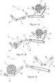
- Figures 1a - c illustrate schematics of an apparatus for recycling artificial or synthetic layered materials in sequential stages throughout a recycling process, in accordance with an embodiment of the present invention.
- an apparatus 1 provided for the recycling and/or repurposing of artificial or synthetic layered materials, in particular, artificial or synthetic grass (AG).
- A artificial or synthetic grass
- the apparatus includes a first conveying section, which in one embodiment of the invention illustrated in the figures comprises a first pair of conveyors 5', 5", on which the artificial grass 3 is initially placed, and a further conveyor 7 along which the artificial grass 3 is passed.
- the artificial grass 3 includes a top layer comprising a fibre layer having a plurality of blades of artificial or synthetic grass.
- the fibre layer may be formed from nylon, polypropylene (PPE) or polyethylene (PE).
- Infill materials are generally dispersed within the fibre layer and between the blades of artificial or synthetic grass.
- the artificial grass 3 passes along the conveyor 7 to a second conveying section, which in this embodiment includes a pair of conveyors 9', 9" positioned to receive and re-roll the subsequently processed artificial grass 3.
- a beating section Located intermediate the first and second conveying sections of the apparatus 1, there is provided a beating section - the section wherein the used artificial grass 3 is processed in a first stage of its recycling / repurposing process.
- the beating section includes at least a first beater 11.
- the artificial grass 3 is unrolled from its first resting position, shown in Figure 1a , along conveyors 5', 5" and toward the second conveyor 7, aided by a guide member 13, such that the artificial grass 3 is inverted along the path of the apparatus 1. That is to say, the top side or layer is arranged to face down along the conveyor 7, and an underside is arranged to face upwardly.
- the artificial grass 3 passes from the first conveying section to the second conveying section in this manner, presenting or exposing the underside thereof to the beater 11.
- the conveyors 7, 9' are pivotable from their resting positions so as to be able to raise the artificial grass 3 closer to the beater 11 (shown in Figure 1b ) while also aiding in "fanning out” blades and/or fibres provided on the top side or layer of the material, thereby loosening and/or removing debris, infill etc. located therebetween.
- the beater 11, provided as an elongate member located across the width of the artificial grass 3 being passed along the apparatus 1 may then be activated by a user to rotate, pivot or oscillate about its longitudinal axis, or move in vertical, horizontal or curved paths as desired by a user so as to impact on, beat, agitate, grind, roll or move along the underside of the artificial grass and essentially hammer, roll, expel or beat out from the top fibre layer of the artificial grass 3 debris, infill and other such particulates therefrom.
- the speed of such movements may also be varied, as required.
- the debris / particulates may drop under gravity from the artificial grass 3 and the grass 3, once sufficiently beaten may continue along the path of the conveyor 7 to be re-rolled in conveyors 9', 9", free of all or the vast majority of infill, debris and particulates etc.
- the beater 11 may be provided having a shaped profile in cross-section. Typically, such shapes may include substantially, square (as shown in the figures), rectangular, triangular or other such profiles in cross-section. Consequently, upon movement of the beater 11, corners and or edges thereof may be arranged to impact, grind, slide and/or move along or on the underside of the grass 3, serving to expel particulates from the grass 3.
- the beating section of the apparatus 1 of the present invention may also include a liquid inlet portion, provided in the form of one or more water jets which are arranged to inject water across, over and/or around the artificial grass 3 as it is being beaten by the beater 11.
- the injection of water is provided to be substantially perpendicular to the path of grass 3 being moved along the apparatus 1, as shown by Arrow A.
- the provision of one or more water jets A serves to wash / rinse and remove debris, infill and other such particulates from artificial grass 3. When dry, i.e.
- the debris or particulates may still hang in the air surrounding the grass 3 and thus may not be fully dislodged or removed therefrom; the provision of a means to inject liquid on and across the grass 3 aids in trapping the particulates and washes / rinses them away from the grass 3.
- An outlet is also provided to enable the outflow of water and the collected / trapped debris / infill / particulates. This is particularly useful as the debris and particulates may subsequently be processed to separate the materials contained therein for subsequent recycling and/or reuse.
- the sand and rubber present in particular can be reused as infill in future AG installations and, consequently, it is advantageous to provide a means by which such material can be filtered, separated and subsequently reused.
- the present invention therefore provides an apparatus 1 which serves to recycles or repurpose artificial or synthetic grass 3 in a far more effective and efficient manner than what is currently known or available in the prior art.
- the apparatus 1 provides a means by which to thoroughly remove all or at least the vast majority of the infill, debris and other particulates that are present or amass over time in between the blades or fibres of the top layer of the AG 3.
- rolls of discarded AG 3 are placed into the apparatus 1, complete with sand and rubber infill.
- a first pair of conveyors 5', 5" then work to unroll the AG 3 with the free end of the AG 3 moving towards a single conveyor 7 (along Arrows B) which in turn directs the free end of the AG 3 to a second pair of conveyors 9', 9" which re-roll the AG 3.
- the single conveyor 7 and one of the second pair of conveyors 9' then articulate (i.e. pivot upwardly as shown in Figure 1b ) so as to present the backing or underside of the AG 3 to a roller/beater 11.
- the roller/beater 11 presses on to the backing or underside of the AG 3, opening up the tufts or blades of synthetic "turf" from one another so that the beating action of the roller/beater 11 dislodges the rubber, compacted sand and other debris contained therein.
- This action is further facilitated by the provision of water jets (arrow A) which help to both wash away the sand and rubber infill while cleaning all the materials at the same time.
- the second pair of conveyors 9', 9" then complete this part of the process by re-rolling the AG 3.
- the components of the second pair of conveyors 9', 9" then move to eject the roll of AG 3 from these conveyors - conveyor 9" may simply pivot downwardly (arrow C) to allow easy removal of the processed AG 3.
- the newly re-rolled AG 3 can then go directly to the next stage of processing/shredding or into storage. In order to achieve the maximum reclaim of sand and rubber at this stage it is possible to slow, stop even reverse the process to allow the roller/beater 11 more time to efficiently process the material.
Landscapes
- Engineering & Computer Science (AREA)
- Environmental & Geological Engineering (AREA)
- Mechanical Engineering (AREA)
- Chemical & Material Sciences (AREA)
- Chemical Kinetics & Catalysis (AREA)
- General Chemical & Material Sciences (AREA)
- Processing Of Solid Wastes (AREA)
Applications Claiming Priority (1)
| Application Number | Priority Date | Filing Date | Title |
|---|---|---|---|
| GBGB1913006.1A GB201913006D0 (en) | 2019-09-10 | 2019-09-10 | Apparatus and method for recycling |
Publications (1)
| Publication Number | Publication Date |
|---|---|
| EP3792028A1 true EP3792028A1 (de) | 2021-03-17 |
Family
ID=68241116
Family Applications (1)
| Application Number | Title | Priority Date | Filing Date |
|---|---|---|---|
| EP20275137.6A Withdrawn EP3792028A1 (de) | 2019-09-10 | 2020-09-08 | Vorrichtung und verfahren zur wiederverwertung |
Country Status (4)
| Country | Link |
|---|---|
| US (1) | US11517945B2 (de) |
| EP (1) | EP3792028A1 (de) |
| CA (1) | CA3092483A1 (de) |
| GB (1) | GB201913006D0 (de) |
Families Citing this family (1)
| Publication number | Priority date | Publication date | Assignee | Title |
|---|---|---|---|---|
| DE102020114923A1 (de) * | 2020-06-04 | 2021-12-09 | Smg Sportplatzmaschinenbau Gmbh | Recyclingvorrichtung und Verfahren zum Betreiben einer Recyclingvorrichtung |
Citations (5)
| Publication number | Priority date | Publication date | Assignee | Title |
|---|---|---|---|---|
| EP0185646A2 (de) * | 1984-12-17 | 1986-06-25 | Monsanto Company | Verfahren zur Behandlung von Kunstrasen |
| EP2387875A1 (de) * | 2010-05-17 | 2011-11-23 | Loon- en Verhuurbedrijf Th. Schuurman en zoon V.O.F. | Vorrichtung zur Beseitigung von Füllmaterial aus einem Streifen Kunstrasen |
| WO2013042816A1 (ko) * | 2011-09-23 | 2013-03-28 | 코오롱글로텍주식회사 | 섬유구조체를 포함하는 인조잔디의 재활용장치 |
| JP2018197482A (ja) * | 2017-05-25 | 2018-12-13 | ▲高▼野商事株式会社 | 人工芝リサイクル方法及びシステム |
| EP3919682A1 (de) * | 2020-06-04 | 2021-12-08 | Smg Sportplatzmaschinenbau Gmbh | Recyclingvorrichtung und verfahren zum betreiben einer recyclingvorrichtung |
Family Cites Families (1)
| Publication number | Priority date | Publication date | Assignee | Title |
|---|---|---|---|---|
| US5263591A (en) * | 1991-12-12 | 1993-11-23 | Taormina Industries, Inc. | Refuse recycling system |
-
2019
- 2019-09-10 GB GBGB1913006.1A patent/GB201913006D0/en not_active Ceased
-
2020
- 2020-09-08 EP EP20275137.6A patent/EP3792028A1/de not_active Withdrawn
- 2020-09-09 CA CA3092483A patent/CA3092483A1/en active Pending
- 2020-09-09 US US16/948,232 patent/US11517945B2/en active Active
Patent Citations (5)
| Publication number | Priority date | Publication date | Assignee | Title |
|---|---|---|---|---|
| EP0185646A2 (de) * | 1984-12-17 | 1986-06-25 | Monsanto Company | Verfahren zur Behandlung von Kunstrasen |
| EP2387875A1 (de) * | 2010-05-17 | 2011-11-23 | Loon- en Verhuurbedrijf Th. Schuurman en zoon V.O.F. | Vorrichtung zur Beseitigung von Füllmaterial aus einem Streifen Kunstrasen |
| WO2013042816A1 (ko) * | 2011-09-23 | 2013-03-28 | 코오롱글로텍주식회사 | 섬유구조체를 포함하는 인조잔디의 재활용장치 |
| JP2018197482A (ja) * | 2017-05-25 | 2018-12-13 | ▲高▼野商事株式会社 | 人工芝リサイクル方法及びシステム |
| EP3919682A1 (de) * | 2020-06-04 | 2021-12-08 | Smg Sportplatzmaschinenbau Gmbh | Recyclingvorrichtung und verfahren zum betreiben einer recyclingvorrichtung |
Non-Patent Citations (1)
| Title |
|---|
| HANTA SYSTEMS COMPANY: "Area Rug / Carpet dust removing machine. Area Rug beater.", YOUTUBE, 29 June 2013 (2013-06-29), pages 1 pp., XP054981316, Retrieved from the Internet <URL:https://www.youtube.com/watch?v=zfMdPyQvP7k> [retrieved on 20210120] * |
Also Published As
| Publication number | Publication date |
|---|---|
| US11517945B2 (en) | 2022-12-06 |
| GB201913006D0 (en) | 2019-10-23 |
| CA3092483A1 (en) | 2021-03-10 |
| US20210069759A1 (en) | 2021-03-11 |
Similar Documents
| Publication | Publication Date | Title |
|---|---|---|
| US8464801B2 (en) | Apparatus for collecting artificial turf for recycling | |
| US20120031814A1 (en) | Recycling of artificial turf | |
| KR101924457B1 (ko) | 골재선별기용 스크린 청소장치 | |
| JP4219962B1 (ja) | 人工芝の張替え方法及び人工芝処理装置 | |
| KR101100325B1 (ko) | 인조잔디 회수기 | |
| KR102152431B1 (ko) | 스크린의 망 막힘을 해소하는 경사형 스크린 토분 선별기 및 선별 방법 | |
| US20050044656A1 (en) | Apparatus and method for treating synthetic grass turf | |
| DE69212153T2 (de) | Vorrichtung zur reinigung von spieloberflächen aus künstlichem rasen | |
| JP3052126U (ja) | 建設廃棄物処理装置 | |
| US11517945B2 (en) | Apparatus and method for recycling | |
| EP3495555A1 (de) | Verfahren zur herstellung eines kunstrasensystems und solches system | |
| JP2000008314A (ja) | 敷設済み砂入り人工芝生の回収方法および装置 | |
| KR100510328B1 (ko) | 이물질 분리제거장치가 구비된 건설폐기물 파분쇄장치 | |
| CN108004901A (zh) | 一种石膏混凝土起沙路面智能复原施工一体机 | |
| CN210279264U (zh) | 一种建筑废料再利用装置 | |
| JP2001336111A (ja) | 砂入り人工芝生の回収方法 | |
| KR20050051428A (ko) | 건설폐기물인 폐 콘크리트를 이용한 모래 재생방법 및재생장치 | |
| CN112024383A (zh) | 一种建筑工程领域的建筑砂石清洗设备 | |
| KR200351067Y1 (ko) | 건설폐기물 토사의 이물질 선별장치 | |
| KR20050084718A (ko) | 건설폐기물 토사의 이물질 선별장치 | |
| JP2009126099A (ja) | 農業用の廃棄マルチシートの再原料化方法 | |
| CN118581791B (zh) | 混凝土路面清理修复装置 | |
| KR200399120Y1 (ko) | 농업용 폐비닐의 재활용을 위한 처리공정 및 그를 위한장치 | |
| KR100557493B1 (ko) | 파분쇄된 건설폐기물의 이물질 선별장치 | |
| CN112047655A (zh) | 一种高强度绿色再生混凝土制备方法 |
Legal Events
| Date | Code | Title | Description |
|---|---|---|---|
| PUAI | Public reference made under article 153(3) epc to a published international application that has entered the european phase |
Free format text: ORIGINAL CODE: 0009012 |
|
| STAA | Information on the status of an ep patent application or granted ep patent |
Free format text: STATUS: THE APPLICATION HAS BEEN PUBLISHED |
|
| AK | Designated contracting states |
Kind code of ref document: A1 Designated state(s): AL AT BE BG CH CY CZ DE DK EE ES FI FR GB GR HR HU IE IS IT LI LT LU LV MC MK MT NL NO PL PT RO RS SE SI SK SM TR |
|
| AX | Request for extension of the european patent |
Extension state: BA ME |
|
| STAA | Information on the status of an ep patent application or granted ep patent |
Free format text: STATUS: REQUEST FOR EXAMINATION WAS MADE |
|
| 17P | Request for examination filed |
Effective date: 20210909 |
|
| STAA | Information on the status of an ep patent application or granted ep patent |
Free format text: STATUS: EXAMINATION IS IN PROGRESS |
|
| 17Q | First examination report despatched |
Effective date: 20230130 |
|
| STAA | Information on the status of an ep patent application or granted ep patent |
Free format text: STATUS: THE APPLICATION IS DEEMED TO BE WITHDRAWN |
|
| 18D | Application deemed to be withdrawn |
Effective date: 20230810 |