EP3792101A1 - Agencement des sièges pour un moyen de transport - Google Patents
Agencement des sièges pour un moyen de transport Download PDFInfo
- Publication number
- EP3792101A1 EP3792101A1 EP20192494.1A EP20192494A EP3792101A1 EP 3792101 A1 EP3792101 A1 EP 3792101A1 EP 20192494 A EP20192494 A EP 20192494A EP 3792101 A1 EP3792101 A1 EP 3792101A1
- Authority
- EP
- European Patent Office
- Prior art keywords
- axis
- frame element
- frame
- seat
- seat arrangement
- Prior art date
- Legal status (The legal status is an assumption and is not a legal conclusion. Google has not performed a legal analysis and makes no representation as to the accuracy of the status listed.)
- Granted
Links
Images






Classifications
-
- B—PERFORMING OPERATIONS; TRANSPORTING
- B60—VEHICLES IN GENERAL
- B60N—SEATS SPECIALLY ADAPTED FOR VEHICLES; VEHICLE PASSENGER ACCOMMODATION NOT OTHERWISE PROVIDED FOR
- B60N2/00—Seats specially adapted for vehicles; Arrangement or mounting of seats in vehicles
- B60N2/70—Upholstery springs ; Upholstery
- B60N2/7011—Upholstery springs ; Upholstery of substantially two-dimensional shape, e.g. hammock-like, plastic shells, fabrics
-
- B—PERFORMING OPERATIONS; TRANSPORTING
- B60—VEHICLES IN GENERAL
- B60N—SEATS SPECIALLY ADAPTED FOR VEHICLES; VEHICLE PASSENGER ACCOMMODATION NOT OTHERWISE PROVIDED FOR
- B60N2/00—Seats specially adapted for vehicles; Arrangement or mounting of seats in vehicles
- B60N2/02—Seats specially adapted for vehicles; Arrangement or mounting of seats in vehicles the seat or part thereof being movable, e.g. adjustable
- B60N2/0292—Multiple configuration seats, e.g. for spacious vehicles or mini-buses
-
- B—PERFORMING OPERATIONS; TRANSPORTING
- B60—VEHICLES IN GENERAL
- B60N—SEATS SPECIALLY ADAPTED FOR VEHICLES; VEHICLE PASSENGER ACCOMMODATION NOT OTHERWISE PROVIDED FOR
- B60N2/00—Seats specially adapted for vehicles; Arrangement or mounting of seats in vehicles
- B60N2/005—Arrangement or mounting of seats in vehicles, e.g. dismountable auxiliary seats
- B60N2/01—Arrangement of seats relative to one another
-
- B—PERFORMING OPERATIONS; TRANSPORTING
- B60—VEHICLES IN GENERAL
- B60N—SEATS SPECIALLY ADAPTED FOR VEHICLES; VEHICLE PASSENGER ACCOMMODATION NOT OTHERWISE PROVIDED FOR
- B60N2/00—Seats specially adapted for vehicles; Arrangement or mounting of seats in vehicles
- B60N2/005—Arrangement or mounting of seats in vehicles, e.g. dismountable auxiliary seats
- B60N2/015—Attaching seats directly to vehicle chassis
-
- B—PERFORMING OPERATIONS; TRANSPORTING
- B60—VEHICLES IN GENERAL
- B60N—SEATS SPECIALLY ADAPTED FOR VEHICLES; VEHICLE PASSENGER ACCOMMODATION NOT OTHERWISE PROVIDED FOR
- B60N2/00—Seats specially adapted for vehicles; Arrangement or mounting of seats in vehicles
- B60N2/02—Seats specially adapted for vehicles; Arrangement or mounting of seats in vehicles the seat or part thereof being movable, e.g. adjustable
- B60N2/20—Seats specially adapted for vehicles; Arrangement or mounting of seats in vehicles the seat or part thereof being movable, e.g. adjustable the back-rest being tiltable, e.g. to permit easy access
- B60N2/203—Seats specially adapted for vehicles; Arrangement or mounting of seats in vehicles the seat or part thereof being movable, e.g. adjustable the back-rest being tiltable, e.g. to permit easy access taking a position opposite to the original one
-
- B—PERFORMING OPERATIONS; TRANSPORTING
- B60—VEHICLES IN GENERAL
- B60N—SEATS SPECIALLY ADAPTED FOR VEHICLES; VEHICLE PASSENGER ACCOMMODATION NOT OTHERWISE PROVIDED FOR
- B60N2/00—Seats specially adapted for vehicles; Arrangement or mounting of seats in vehicles
- B60N2/02—Seats specially adapted for vehicles; Arrangement or mounting of seats in vehicles the seat or part thereof being movable, e.g. adjustable
- B60N2/22—Seats specially adapted for vehicles; Arrangement or mounting of seats in vehicles the seat or part thereof being movable, e.g. adjustable the back-rest being adjustable
-
- B—PERFORMING OPERATIONS; TRANSPORTING
- B60—VEHICLES IN GENERAL
- B60N—SEATS SPECIALLY ADAPTED FOR VEHICLES; VEHICLE PASSENGER ACCOMMODATION NOT OTHERWISE PROVIDED FOR
- B60N2/00—Seats specially adapted for vehicles; Arrangement or mounting of seats in vehicles
- B60N2/24—Seats specially adapted for vehicles; Arrangement or mounting of seats in vehicles for particular purposes or particular vehicles
- B60N2/242—Bus seats
-
- B—PERFORMING OPERATIONS; TRANSPORTING
- B60—VEHICLES IN GENERAL
- B60N—SEATS SPECIALLY ADAPTED FOR VEHICLES; VEHICLE PASSENGER ACCOMMODATION NOT OTHERWISE PROVIDED FOR
- B60N2/00—Seats specially adapted for vehicles; Arrangement or mounting of seats in vehicles
- B60N2/64—Back-rests or cushions
- B60N2/643—Back-rests or cushions shape of the back-rests
-
- B—PERFORMING OPERATIONS; TRANSPORTING
- B60—VEHICLES IN GENERAL
- B60N—SEATS SPECIALLY ADAPTED FOR VEHICLES; VEHICLE PASSENGER ACCOMMODATION NOT OTHERWISE PROVIDED FOR
- B60N2/00—Seats specially adapted for vehicles; Arrangement or mounting of seats in vehicles
- B60N2/68—Seat frames
-
- B—PERFORMING OPERATIONS; TRANSPORTING
- B61—RAILWAYS
- B61D—BODY DETAILS OR KINDS OF RAILWAY VEHICLES
- B61D1/00—Carriages for ordinary railway passenger traffic
- B61D1/04—General arrangements of seats
-
- B—PERFORMING OPERATIONS; TRANSPORTING
- B61—RAILWAYS
- B61D—BODY DETAILS OR KINDS OF RAILWAY VEHICLES
- B61D33/00—Seats
- B61D33/0007—Details; Accessories
- B61D33/0014—Seat frames
-
- B—PERFORMING OPERATIONS; TRANSPORTING
- B61—RAILWAYS
- B61D—BODY DETAILS OR KINDS OF RAILWAY VEHICLES
- B61D33/00—Seats
- B61D33/0007—Details; Accessories
- B61D33/0014—Seat frames
- B61D33/0028—Seat frames for reversible seats
-
- B—PERFORMING OPERATIONS; TRANSPORTING
- B61—RAILWAYS
- B61D—BODY DETAILS OR KINDS OF RAILWAY VEHICLES
- B61D33/00—Seats
- B61D33/0007—Details; Accessories
- B61D33/0035—Cushions or the like; Covers
-
- B—PERFORMING OPERATIONS; TRANSPORTING
- B61—RAILWAYS
- B61D—BODY DETAILS OR KINDS OF RAILWAY VEHICLES
- B61D33/00—Seats
- B61D33/0007—Details; Accessories
- B61D33/005—Head, arm or footrests
-
- B—PERFORMING OPERATIONS; TRANSPORTING
- B61—RAILWAYS
- B61D—BODY DETAILS OR KINDS OF RAILWAY VEHICLES
- B61D33/00—Seats
- B61D33/0057—Seats characterised by their mounting in vehicles
- B61D33/0078—Seats characterised by their mounting in vehicles adjustably mounted
-
- B—PERFORMING OPERATIONS; TRANSPORTING
- B64—AIRCRAFT; AVIATION; COSMONAUTICS
- B64D—EQUIPMENT FOR FITTING IN OR TO AIRCRAFT; FLIGHT SUITS; PARACHUTES; ARRANGEMENT OR MOUNTING OF POWER PLANTS OR PROPULSION TRANSMISSIONS IN AIRCRAFT
- B64D11/00—Passenger or crew accommodation; Flight-deck installations not otherwise provided for
- B64D11/06—Arrangements of seats, or adaptations or details specially adapted for aircraft seats
- B64D11/0611—Arrangements of seats, or adaptations or details specially adapted for aircraft seats with means for holding the passenger in a standing position
-
- B—PERFORMING OPERATIONS; TRANSPORTING
- B64—AIRCRAFT; AVIATION; COSMONAUTICS
- B64D—EQUIPMENT FOR FITTING IN OR TO AIRCRAFT; FLIGHT SUITS; PARACHUTES; ARRANGEMENT OR MOUNTING OF POWER PLANTS OR PROPULSION TRANSMISSIONS IN AIRCRAFT
- B64D11/00—Passenger or crew accommodation; Flight-deck installations not otherwise provided for
- B64D11/06—Arrangements of seats, or adaptations or details specially adapted for aircraft seats
- B64D11/0639—Arrangements of seats, or adaptations or details specially adapted for aircraft seats with features for adjustment or converting of seats
- B64D11/064—Adjustable inclination or position of seats
-
- B—PERFORMING OPERATIONS; TRANSPORTING
- B64—AIRCRAFT; AVIATION; COSMONAUTICS
- B64D—EQUIPMENT FOR FITTING IN OR TO AIRCRAFT; FLIGHT SUITS; PARACHUTES; ARRANGEMENT OR MOUNTING OF POWER PLANTS OR PROPULSION TRANSMISSIONS IN AIRCRAFT
- B64D11/00—Passenger or crew accommodation; Flight-deck installations not otherwise provided for
- B64D11/06—Arrangements of seats, or adaptations or details specially adapted for aircraft seats
- B64D11/0648—Lower frame constructions
-
- B—PERFORMING OPERATIONS; TRANSPORTING
- B60—VEHICLES IN GENERAL
- B60N—SEATS SPECIALLY ADAPTED FOR VEHICLES; VEHICLE PASSENGER ACCOMMODATION NOT OTHERWISE PROVIDED FOR
- B60N2/00—Seats specially adapted for vehicles; Arrangement or mounting of seats in vehicles
- B60N2/24—Seats specially adapted for vehicles; Arrangement or mounting of seats in vehicles for particular purposes or particular vehicles
- B60N2002/247—Seats specially adapted for vehicles; Arrangement or mounting of seats in vehicles for particular purposes or particular vehicles to support passengers in a half-standing position
-
- B—PERFORMING OPERATIONS; TRANSPORTING
- B64—AIRCRAFT; AVIATION; COSMONAUTICS
- B64D—EQUIPMENT FOR FITTING IN OR TO AIRCRAFT; FLIGHT SUITS; PARACHUTES; ARRANGEMENT OR MOUNTING OF POWER PLANTS OR PROPULSION TRANSMISSIONS IN AIRCRAFT
- B64D11/00—Passenger or crew accommodation; Flight-deck installations not otherwise provided for
- B64D11/06—Arrangements of seats, or adaptations or details specially adapted for aircraft seats
Definitions
- the invention relates to a seat arrangement for a means of transport, in particular for a means of passenger transport, the seat arrangement being arranged on the means of transport by means of a fastening device.
- Such means of transport are intended and suitable for being able to transport a large number of people and are, for example, rail vehicles or aircraft.
- Corresponding rail vehicles are, for example, local and / or long-distance trains, S-Bru, U-Bru and the like.
- the provision of standing places means that there is space for significantly more people traveling in the means of transport.
- standing room also means an often unacceptable loss of travel comfort, especially on longer journeys.
- Another disadvantage of the previous seat arrangements is that they cannot be modified with regard to the needs of the user.
- the orientation of the seats cannot be changed. It is generally not possible to adapt the alignment, for example, to the direction of travel of the means of transport.
- groups of seats are also usually provided in which two pairs of seats face one another or in which the pairs of seats are arranged in a row one behind the other. Accordingly, it is not possible to adapt to the needs of small travel groups or families using such seating groups.
- the object of the present invention is to provide a seat arrangement which overcomes the disadvantages mentioned at the beginning. Furthermore, it is the object of the invention to provide an interior arrangement of a means of transport which overcomes the disadvantages mentioned at the beginning.
- An essential point of the invention is to provide a seat arrangement for a means of transport, in particular for a means of passenger transport, wherein the seat arrangement can be arranged on or in the means of transport by means of a fastening device.
- the seat arrangement is intended and suitable to provide a sitting position at standing height, the seat arrangement comprising at least one frame element which is arranged on the fastening device by means of at least one bearing axis, with at least one frame element about a pivot axis extending along a width axis (Y) relative to the fastening device is pivotable.
- a coordinate system with a height axis (X), a width axis (Y) and a depth axis (X) is used for the seat arrangement.
- a coordinate system with a height axis (X '), a width axis (Y') and a depth axis (X ') is used for the at least one frame element.
- the respective axes can furthermore each have two directions.
- the frame element preferably comprises an upper area for supporting the back and at least one seat area integrated in the at least one frame element.
- the at least one frame element accordingly takes on the function of a backrest and equally the function of a seat part. Accordingly, an extremely simple and inexpensive to manufacture seat arrangement is provided.
- the first and the second seat area of the at least one frame element preferably extend along a depth axis (X ') which is between 10 cm and 50 cm, more preferably between 15 cm and 40 cm.
- the seating area is arranged at a height that enables sitting or leaning at standing height.
- Such seating arrangements are also referred to as standing seats. Due to the advantageous configuration as a standing seat, the occupant of the seat arrangement does not assume a classic sitting posture. Rather, the occupant assumes a sitting posture in the seat arrangement which approximately corresponds to a standing posture. Compared to the classic sitting posture, in which the legs are bent approximately at right angles, this sitting posture requires a significantly smaller amount of space.
- the advantageous seat arrangement thus has a much smaller depth than a conventional seat. The passengers of the means of transport are therefore offered an extremely simple, yet comfortable option to sit in a standing position.
- the seat area is advantageously arranged at a height between 40 cm and 150 cm, more preferably at a height between 40 cm and 130 cm.
- the seat height can advantageously be matched to the intended target persons. For example, a seat arrangement which is intended for children or the elderly would preferably have a seat height in a range between 40 cm and 60 cm. A seating arrangement for adults would rather have a height in a range between 80 cm and 150 cm, more preferably in a range between 80 cm and 130 cm.
- the at least one frame element is formed by a lower section and an upper section.
- the at least one frame element preferably has a base area which extends along a height axis (Z ') and along a width axis (Y').
- This base area is preferably designed as a polygon.
- the base is preferably designed as a square.
- the base area is preferably designed essentially as a rectangle or essentially as a trapezoid.
- the term “essentially” used is to be interpreted in such a way that slight tolerance deviations with regard to a shape, a length or an angle are also claimed. The deviation can thus amount to an angle of preferably less than 10 °, more preferably less than 7.5 °, even more preferably less than 5 °.
- the lower section and the upper section of the at least one frame element form the at least one frame element in one piece, in one piece or in several pieces, in particular in two pieces.
- the frame element, or the upper and lower sections is a single and unitary part, or a so-called one Monoblock made.
- the respective sections are advantageously made from the same material.
- a one-piece design here means that although all sections are not made from a single and unitary part, they are not only firmly but so intimately connected that they do not appear as several components joined to one another and in any case no longer detached from one another without them being destroyed in the process.
- the lower section advantageously comprises at least one first transverse section extending essentially along a width axis (Y ') and a second transverse section extending essentially along a width axis (Y').
- the upper section comprises a third transverse section extending along the width axis (Y ').
- the first transverse section and the second transverse section preferably extend along a depth axis (X '). This extension is advantageously enlarged compared to an extension of the third transverse section along the depth axis.
- the first and / or the second transverse section preferably forms the seat area at least in sections.
- the first and second transverse sections extend in opposite directions along the depth axis.
- the first and the second transverse section are preferably connected to one another.
- the first and the second transverse section are preferably formed in one piece or in one piece.
- the first and the second transverse section are advantageously spaced apart from the third transverse section along the height axis (Z ') and are connected by means of two strut elements.
- the first transverse section and the second transverse section preferably have a greater extent along a depth axis (X ') than the third transverse section. It is advantageous that the lower section and the upper section enclose an inner surface.
- the first and the second transverse section enclose the two strut elements and the third transverse section enclose the inner surface.
- the at least one frame element is essentially plate-like, the first and second transverse sections being provided with an enlarged depth extension at the lower end along the height axis, whereby the seat area is formed at least in sections.
- the at least one frame element can be pivoted relative to the fastening device about a pivot axis extending along a width axis (Y ', Y).
- the at least one frame element can accordingly be pivoted as a whole with respect to a pivot axis.
- both the advantageous upper area for supporting the back and the advantageous integrated seat area are pivoted or rotated at the same time about the pivot axis.
- the at least one frame element can be pivoted into at least two pivot positions.
- the at least one frame element is preferably pivotable in three pivot positions.
- the at least one frame element is preferably pivotable into a first pivot position.
- the frame element In the first pivot position, the frame element preferably extends essentially perpendicular to a fictitious plane which extends parallel to the floor of the means of transport.
- the at least one frame element can advantageously be pivoted into a second pivot position which is inclined relative to the first pivot position by an angle of inclination (a).
- the at least one frame element is preferably pivotable into a third pivot position which is inclined relative to the first pivot position by an angle of inclination ( ⁇ ).
- a second fictitious plane can advantageously be defined, which runs perpendicular to the first fictitious plane.
- the at least one frame element In the first pivot position, the at least one frame element is advantageously arranged essentially in the second fictitious plane.
- the at least one frame element In the second and the third pivot position, the at least one frame element preferably encloses an angle of inclination ⁇ or ⁇ with the second fictitious plane. It is advantageous that the at least one frame element is inclined in the second and third pivot positions in opposite directions along a depth axis (X).
- the angle of inclination ( ⁇ ) and the angle of inclination ( ⁇ ) thus advantageously have a different sign ( ⁇ ).
- the angle of inclination ( ⁇ ) and the angle of inclination ( ⁇ ) preferably have the same amount.
- angles of inclination ( ⁇ , ⁇ ) are preferably in a range between 10 ° and 80 °, more preferably in a range between 20 ° and 70 °, the at least one frame element and the second fictitious plane including the angles of inclination ( ⁇ , ⁇ ).
- the at least one mounting axis enables pivoting or rotation of the at least one frame element about the pivot axis.
- the pivot axis preferably extends through or along the mounting axis.
- only one bearing axis is provided.
- This mounting axis is received in at least one receiving device of the fastening device.
- the mounting axis is preferably received in two receiving devices of the fastening device which are spaced apart from one another along the width axis (Y, Y ').
- At least one frame element is advantageously arranged between two receiving devices of the fastening device.
- a through channel for the bearing axis is provided at the lower end of the at least one frame element along a height axis (Z ').
- the bearing axis advantageously extends through the through channel of the at least one frame element.
- the through channel is preferably provided in the lower section of the at least one frame element.
- the through channel can preferably extend over the entire width of the at least one frame element.
- the through channel preferably extends over a substantial section along the width direction of the at least one frame element.
- Such an essential section preferably corresponds to at least half, more preferably at least three quarters of the total width extension of the at least one frame element.
- the through-channel is not continuously closed.
- the through-channel has at least one, preferably two, storage areas which are formed by the at least one frame element or are arranged on the at least one frame element. In the rest of the course, the bearing axis could preferably be exposed.
- the bearing axis is non-rotatably or mechanically rigidly connected to the fastening device or to the at least one receiving device of the fastening device. It is advantageous that the at least one frame element is pivotable or rotatable relative to and on the mounting axis. It would also be conceivable that the bearing axis is non-rotatably or mechanically rigidly connected to the at least one frame element. It is advantageous that the mounting axis is rotatably mounted in the at least one, preferably two, receiving device (s). The at least one frame element and the mounting axis then pivot or rotate relative to the at least one, preferably two, receiving device (s).
- two mounting axes are provided, which are arranged on the lower section of the at least one frame element on the respective sides opposite along the width axis (Y, Y ') in such a way that these along the width axis (Y, Y') over the at least a frame element protrude.
- the two mounting axes are then rotatably mounted in a respective receiving device of the fastening element.
- the at least one bearing axis has at least one stop element. At least one further stop element is preferably arranged in the through channel. It is advantageous here that, during a pivoting movement of the at least one frame element, the at least one further stop element of the through-channel is displaced along a circumferential direction of the mounting axis relative to the mounting axis. This is preferably at least in the second pivot position a further stop element of the through-channel on a first stop surface of the at least one stop element of the bearing axis. In the third pivot position, the at least one further stop element of the through-channel preferably rests against a second stop surface of the at least one stop element of the mounting axis.
- the bearing axis and the through-channel each have two stop elements arranged opposite one another.
- the at least one bearing axis is essentially hollow-cylindrical with an essentially circular cross-section, for example as a profile tube.
- the at least one stop element of the bearing axis could preferably be designed as a recess in a lateral surface of the bearing axis.
- the at least one further stop element of the through-channel is advantageously designed as a projection which is arranged on an inner surface of the through-channel and protrudes into the recess of the mounting axis.
- the at least one stop element of the bearing axis is designed as a projection which protrudes into a further stop element, designed as a recess, of the through-channel. This recess can advantageously be arranged on an inner surface of the through channel.
- a locking device by means of which the at least one frame element can be locked in at least one pivot position.
- the at least one frame element can preferably be locked in at least two or at least three pivoting positions by means of the locking device.
- the at least one frame element can advantageously be locked in all provided pivot positions by means of the locking device. If the at least one frame element is pivoted into the first pivot position and locked in this pivot position, it is aligned upright and essentially arranged in the second fictitious plane, which runs perpendicular to the first fictitious plane. In this position, the seat arrangement is not occupied by a user.
- the effective depth of the seat arrangement in this position corresponds essentially to the sum of the depth extensions of the first and second transverse sections of the at least one frame element.
- the seat arrangement accordingly takes up minimal space in the first pivot position along the depth axis.
- the fact that extremely little space is required when the at least one frame element extends upright enables the seat arrangement, for example, to be effectively supported.
- the space can be enlarged by pivoting into the first pivot position.
- a first seat area is formed at least by the first transverse section.
- a second seat area is preferably formed at least by the second transverse section.
- the at least one frame element can advantageously be pivoted into the first pivot position, into the second pivot position and into the third pivot position and can advantageously be locked in these pivot positions.
- the first and second seat areas Due to the preferred extension of the first transverse section and the second transverse section in opposite directions along the depth axis (X) and due to the opposite angles of inclination ( ⁇ , ⁇ ) of the at least one frame element in the second and third pivot positions, the first and second seat areas are in along directions opposite to the depth axis (X).
- Such a configuration allows an extremely simple adaptation of the seat orientation to the direction of travel. With some means of transport, such as rail vehicles, a change of direction can take place while driving. This can take place, for example, when entering or exiting a terminal station. However, some users react with discomfort to reversing. By simply swiveling from the second to the third swivel position, for example, the orientation of the seat arrangement can be easily adapted to the direction of travel.
- the at least one frame element can be pivoted into the first pivot position and into the second pivot position and can advantageously be locked in these pivot positions.
- An embodiment would also be conceivable in which the at least one frame element can be pivoted into the first pivot position and into the third pivot position and can advantageously be locked in these pivot positions.
- the seat arrangement would therefore continue to be configured in an upright swivel position for only one seat direction.
- the at least one frame element can be pivoted into the second pivot position and into the third pivot position and can advantageously be locked in these pivot positions.
- the seat arrangements would be designed for two opposite seating directions. However, no upright pivot position would be provided for storage.
- the at least one frame element can only assume the second pivot position or the third pivot position and is firmly locked or fixed in this pivot position.
- the at least one frame element can be pivoted into further pivot positions and can be locked in these pivot positions. Such further pivot positions could be between the first pivot position and the second pivot position or between the first pivot position and the third pivot position.
- the corresponding angles of inclination would then be smaller than the angles of inclination ( ⁇ , ⁇ ). This allows the occupant to adjust the inclination of the upper section to support the back according to his needs.
- the first seat area in the second pivot position of the at least one frame element, the first seat area extends essentially parallel to the first fictitious plane, or horizontally.
- the second seat area In the third pivot position of the at least one frame element, the second seat area preferably extends essentially parallel to the first fictitious plane, or horizontally.
- the first transverse section preferably comprises an upper surface which, in the second pivot position, extends essentially parallel to the first fictitious plane.
- the second transverse section advantageously comprises an upper surface which, in the third pivot position, extends essentially parallel to the first fictitious plane.
- the locking device is arranged on the at least one frame element.
- the locking device preferably comprises a first locking element which can be brought into engagement with at least one further locking element of the bearing axis. It is advantageous here that a further locking element of the mounting axis is assigned to each pivot position of the at least one frame element.
- the locking device comprises an operating element, by means of which the first locking element can be displaced.
- a reset device is preferably actuated during the displacement movement in order to release this engagement.
- the restoring device is a compression spring element or an elastic element.
- the first locking element can preferably be displaced by the restoring device, which enables engagement with the at least one further locking element of the bearing axis.
- the operating element is arranged on the lower section of the at least one frame element by means of a holding element.
- the operating element is advantageously arranged on the first locking element so as to be pivotable by means of an axis. It is advantageous that at least one support section of the operating element is on abuts a collar of the retaining element.
- the first locking element is advantageously displaced outward in the radial direction, as a result of which the engagement with the at least one further locking element is released.
- the first locking element is preferably designed like a pin and protrudes at least in sections through the through channel of the at least one frame element.
- the at least one further locking element is preferably designed as a recess or bore in a lateral surface of the bearing axis.
- Three further locking elements in the form of a recess or bore are preferably provided on the mounting axis.
- the jacket surface has an arc-like course and the three further locking elements in the form of a recess or bore are arranged one after the other along the circumferential direction. In each lockable pivot position provided, a corresponding further locking element is preferably arranged in such a way that engagement with the first locking element can take place.
- At least one grip element is provided on the at least one frame element.
- the at least one grip element is preferably arranged on one of the strut elements in an upper region along the height axis. Accordingly, the grip element is arranged entirely or at least in sections on the upper section of the at least one frame element.
- the seat arrangement advantageously has a first outside and a second outside.
- the grip element is advantageously arranged on an outside which, when installed in the means of transport, lies on a passage.
- the grip elements thus form a holding option for standing passengers or passing passengers. It would be conceivable that only the first outer side lies on a passage of the means of transport. In this case it is advantageous if the grip element is arranged on the first outside of the seat arrangement.
- a grip element to be arranged on the first and on the second outer side of the seat arrangement. This would be advantageous, for example, if two passages are provided in the means of transport.
- the arrangement of the handle elements is not limited to the arrangement with respect to the passages.
- Such grip elements can also have other functions, such as, for example, support when standing up, etc.
- the seat arrangement comprises only one frame element which is arranged on the fastening device.
- the frame element is arranged between two receiving devices of the fastening device.
- Each of the receiving devices is preferably arranged on a fastening element which is suitable and provided for attaching the receiving device to the means of transport.
- the fastening elements advantageously comprise arm elements which extend along the height axis (Z) and which open into a base element.
- the base element is preferably arranged centrally to, and along the height axis (Z) below, the frame element.
- the arm elements are designed to converge downwards along the height axis (Z). With such a configuration, the seating arrangement can be made extremely simple.
- the fastening element acts directly on the mounting axis for the frame element.
- the base element can advantageously be fixed directly to the floor of the means of transport. It would also be conceivable that the fastening device or the base element is arranged displaceably on the floor of the means of transport by means of a guide system.
- the seat arrangement comprises two frame elements which are arranged on the fastening device.
- the two frame elements are preferably arranged next to one another along the width axis (Y).
- the two frame elements can be designed in the same way or different.
- Each of the two frame elements can have features according to the embodiments described above, independently of one another.
- a first and a second outer side of the seat arrangement can preferably be defined. If the seat arrangement comprises two frame elements, an outer side of the seat arrangement is represented by one of the two frame elements.
- the already described at least one grip element can be arranged on one of the two outer sides. In an installed state, the outside with the grip element is advantageously located on a passage of the means of transport.
- the two frame elements can be pivoted independently of one another about a common pivot axis extending along a width axis (Y) relative to the fastening device.
- the two frame elements are preferably, as already described, independently of one another around the Angle of inclination ( ⁇ , ⁇ ) can be pivoted into the first, second and third pivot positions.
- only one bearing axis is provided.
- the mounting axis advantageously extends at least over the entire width of the two frame elements.
- the bearing axis extends through the through channels of the two frame elements.
- the mounting axis is preferably received in at least two, preferably exactly two, receiving devices of the fastening device.
- a first receiving device is arranged between the two frame elements.
- a further second receiving device is preferably arranged to the side of one of the two frame elements or on one of the two outer sides of the seat arrangement.
- the two frame elements are arranged between two laterally arranged receiving devices.
- Each of the receiving devices is preferably arranged on a fastening element which is suitable and provided for fastening the receiving device to the means of transport.
- At least one fastening element advantageously comprises an arm element extending along the height axis (Z).
- only one arm element is provided and a further fastening element is arranged on a wall element of the means of transport.
- both fastening elements comprise arm elements which extend along the height axis (Z) below the frame elements.
- the respective fastening element and the respective receiving devices are designed in one piece or in one piece.
- the at least one frame element is made from a metal alloy, preferably from an aluminum alloy.
- the fastening device can also be made at least partially from a metal alloy, preferably from an aluminum alloy.
- the seat arrangement can be built as light as possible.
- a seat cover is arranged on or in the at least one frame element.
- the at least one frame element preferably includes an inner surface.
- the seat cover is therefore advantageously arranged in this inner surface.
- the seat cover is arranged on or above the inner surface. It would also be conceivable that the seat cover encloses the inner surface at least in sections.
- the seat cover is advantageously provided and intended to to withstand the force applied by the user.
- the seat cover accordingly advantageously has a corresponding stability. Accordingly, no further supporting elements are advantageously arranged in the inner surface.
- the seat cover is preferably a knitted fabric.
- the seat cover is preferably a tubular knitted fabric or a flat knitted fabric.
- an interior device of a means of transport in particular a means of passenger transport, which comprises at least one seat arrangement according to one of the preceding embodiments.
- the interior arrangement can be equipped with all the features already described above in the context of the seat arrangement individually or in combination with one another and vice versa.
- the interior arrangement preferably comprises a plurality of seat arrangements.
- the at least one seat arrangement is arranged on the transport means in a stationary manner or displaceably by means of a guide device, in particular a rail device.
- the guide device can be arranged on the floor or on a wall element of the means of transport.
- the seat arrangements can thus advantageously be accommodated in a stowage area of the means of transport, for example a rail vehicle.
- the space of the means of transport could thus be filled with bulky luggage, for example bicycles.
- a certain number of seating arrangements can be moved from the stowage area into the interior and can be set accordingly at certain points. This can be done by appropriate advantageous locking devices.
- a means of transport in particular a means of passenger transport, for example a rail vehicle, is provided which has at least one interior device or at least one seating arrangement.
- a seat arrangement 1 for a means of transport 101 in particular for a means of passenger transport, is shown, wherein the seat arrangement 1 can be arranged on or in the means of transport 101 by means of a fastening device 5, the seat arrangement 1 being intended and suitable for providing a sitting position at standing height, with the seat arrangement 1 comprises at least one frame element 2, 2a, 2b, which is arranged by means of at least one bearing axis 22 on the fastening device 5, at least one frame element 2, 2a, 2b about a pivot axis (6) extending along a width axis Y relative to the Fastening device 5 is pivotable.
- a coordinate system with a height axis X, a width axis Y and a depth axis X is used for the seat arrangement.
- a coordinate system with a height axis X ', a width axis Y' and a depth axis X ' is used for the at least one frame element.
- the respective axes can furthermore each have two directions.
- the at least one frame element 2, 2a, 2b comprises an upper area 3 for supporting the back and at least one seat area 4, 4a, 4b integrated in the at least one frame element 2, 2a, 2b.
- the at least one frame element 2, 2a, 2b accordingly takes on the function of a backrest and equally the function of a seat part. Accordingly, an extremely simple and inexpensive to manufacture seat arrangement 1 is provided.
- the seat arrangement 1 is shown, which only comprises a frame element 2 arranged on the fastening device 5.
- seat arrangements 1 which each comprise two frame elements 2, 2a, 2b.
- different pivot positions are shown, which apply both to a seat arrangement 1 with a frame element 2 and to a seat arrangement 1 with two frame elements 2, 2a, 2b.
- the seat arrangement 1 is intended and suitable for providing a sitting position at standing height.
- Such seating arrangements 1 are also referred to as a standing seat.
- the seating area is preferably arranged at a height between 40 cm and 150 cm, more preferably at a height between 50 cm and 130 cm.
- the seat height can advantageously be matched to the intended target persons.
- 1b is for example a seating arrangement 1 shown, which is more suitable for children or the elderly.
- the seat height is preferably in a range between 40 cm and 60 cm.
- a seat arrangement 1 is shown, which is more suitable for adults.
- the seat height here would rather be in a range between 80 cm and 150 cm, more preferably in a range between 90 cm and 130 cm.
- the at least one frame element 2, 2a, 2b can be designed identically in the configuration of the seat arrangement 1 with one frame element 2, 2a, 2b and in the configuration of the seat arrangement 1 with two frame elements 2, 2a, 2b.
- the at least one frame element 2, 2a, 2b is formed by a lower section 7 and an upper section 8.
- the lower section 7 comprises at least one first transverse section 9 extending essentially along a width axis Y, Y 'and a second transverse section 10 extending essentially along a width axis Y, Y'.
- the first and second transverse sections are preferably in one piece or in one piece educated.
- the first 9 and the second transverse section 10 can have recesses arranged in a honeycomb lattice structure (see for example Figure 15 ).
- the upper section 8 furthermore comprises a third transverse section 11 extending along the width axis Y, Y '.
- the two width axes Y, Y' are congruent here.
- the first transverse section 9 and the second transverse section 10 are spaced apart from the third transverse section 11 along the height axis Z ′.
- the first transverse section 9 and the second transverse section 10 are connected by means of two strut elements 27.
- the at least one frame element 2, 2a, 2b accordingly comprises an inner surface 28 which is bordered by the upper section 8 and the lower section 7, or by the third transverse section, the two strut elements 27, the first transverse section 9 and the second transverse section 10.
- the at least one frame element 2, 2a, 2b is essentially trapezoidal.
- the third transverse section 11 has a smaller width than the first 9 and second transverse section 10.
- the first transverse section 9 and the second transverse section 10 have a greater extent along a depth axis X 'than the third transverse section 11.
- the first transverse section 9 or the second Transverse section 10 form, at least in sections, the seat area 4, 4a, 4b.
- the lower section 7 and the upper section 8 of the at least one frame element 2, 2a, 2b form the at least one frame element 2, 2a, 2b in one piece, in one piece or in several pieces.
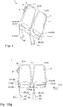
- a one-piece design of the frame element (s) 2, 2a, 2b is shown in the area bordered by dashed lines.
- a further embodiment of the frame element (s) 2, 2a, 2b is shown, in which this / these is / are designed in two parts.
- the at least one frame element consists of a lower section 7 and an upper section 8, both sections 7 and 8 being U-shaped.
- the two strut elements 27 are interrupted and connected by means of a preferably releasable connection, preferably a plug connection.
- a releasable connection is, for example, a plug connection.
- two sections of the strut element are each plugged into one another.
- securing devices such as pins, screws, bolts, etc. are also provided, by means of which the plug connection can be secured against unintentional loosening.
- the at least one frame element 2, 2a, 2b can be pivoted about a pivot axis 6 extending along a width axis Y relative to the fastening device 5.
- the at least one frame element 2, 2a, 2b can be pivoted as a whole with respect to the pivot axis 6.
- both the upper area 3 for supporting the back and the integrated seat area 4, 4a, 4b are pivoted or rotated at the same time about the pivot axis 6.
- the backrest can be pivoted about a pivot axis.
- the at least one frame element 2, 2a, 2b is preferably pivotable in at least two pivot positions 12a, 12b, 12c, more preferably the at least one frame element 2, 2a, 2b is pivotable in three pivot positions 12a, 12b, 12c.
- These pivot positions 12a, 12b, 12c are, for example, in FIG Figure 3 shown.
- the double arrow 15 is also shown, which once again clarifies the pivoting directions.
- the at least one frame element 2, 2a, 2b can be pivoted into a first pivot position 12a, the at least one frame element 2, 2a, 2b in the first pivot position 12a) extending essentially perpendicular to a first fictitious plane 13, which extends parallel to the Floor 102 of the means of transport 101 extends.
- the at least one frame element 2, 2a, 2b extends upright or essentially parallel to the height axis Z of the seat arrangement 1 in the first pivot position the extension of the first 9 and second transverse section 10 corresponds.
- the at least one frame element 2, 2a, 2b can be pivoted into a second pivot position 12b, which is inclined relative to the first pivot position 12a by an angle of inclination ⁇ .
- the at least one frame element 2, 2a, 2b can be pivoted into a third pivot position 12c, which is inclined relative to the first pivot position 12a by an angle of inclination ⁇ .
- a second fictitious plane 14 can be defined, which runs perpendicular to the first fictitious plane 13.
- the at least one frame element 2, 2a, 2b is arranged essentially in the second fictitious plane 14 in the first pivot position. In the second 12b and the third pivot position 12c, the at least one frame element 2, 2a, 2b in each case encloses the angle of inclination ⁇ or ⁇ with the second fictitious plane 14.
- the at least one frame element 2, 2a, 2b is inclined in the second pivot position 12b and the third pivot position 12c in opposite directions along the depth axis X.
- the angles of inclination ⁇ and ⁇ thus have a different sign ( ⁇ ), but the same amount.
- angles of inclination ⁇ , ⁇ are preferably in a range between 10 ° and 80 °, more preferably in a range between 20 ° and 70 °, the at least one frame element 2, 2a, 2b and the second fictitious plane 14 including the angles of inclination ⁇ , ⁇ .
- a locking device 29 is provided, by means of which the at least one frame element 2, 2a, 2b can be locked in at least one pivot position 12a, 12b, 12c.
- the at least one frame element 2, 2a, 2b can preferably be locked in the first 12a, the second 12b and the third pivot position 12c. It would also be conceivable that the at least one frame element 2, 2a, 2b can only be locked in the second 12b and the third pivot position 12c. It is also conceivable that the at least one frame element can assume at least the second and third pivot position without the frame element 2, 2a, 2b being locked.
- the frame element remains in this corresponding pivot position 12b, 12c even without any further locking.
- the at least one frame element remains in the pivoted position 12b, 12c.
- a first seat area 4, 4a is formed at least by the first transverse section 9. This is for example in the Figures 1a and 2a recognizable.
- a second seat area 4, 4b is formed at least by the second transverse section 10. This is for example in the Figures 1b and 2b recognizable.
- the first seat area 4, 4a extends essentially parallel to the first fictitious plane 13.
- the second pivot position 12c of the at least one frame element 2, 2a, 2b the second extends Seat area 4, 4b essentially parallel to the first fictitious plane 13. This essentially parallel extension of the first or second seat area 4, 4a, 4b enables the occupant to sit comfortably.
- FIGS 11a to 11d and 12a to 12d seat arrangements 1 with two frame elements 2, 2a, 2b in different pivoting positions 12a, 12b, 12c are shown.
- the Figures 11a to 11d differ from the Figures 12a to 12d of the design of the fastening device 5.
- Seat arrangements 1, which comprise a fastening device 5 according to one of the further possible configurations, can, however, also assume these pivoting positions shown.
- the two frame elements 2, 2a, 2b are in the second pivot position 12b.
- the first seat area 4, 4a in the form of the first transverse section 9 is thus provided by each of the frame elements 2, 2a, 2b.
- the two frame elements 2, 2a, 2b are in the third pivot position 12c.
- the second seat area 4, 4b in the form of the second transverse section 10 is thus provided by each of the frame elements 2, 2a, 2b.
- the first frame element 2a is in the second pivot position 12b, whereby the first seat area 4, 4a is provided in the form of the first transverse section 9.
- the second frame element 2b is located in the third pivot position 12c, as a result of which the second seat area 4, 4b is provided in the form of the second transverse section 10.
- the first frame element 2a is in the third pivot position 12c, whereby the second seat area 4, 4b is provided in the form of the second transverse section 10.
- the second frame element 2b is in the second pivot position 12b, whereby the first seat area 4, 4a is provided in the form of the first transverse section 9.
- Such a configuration allows seating groups consisting of such seating arrangements 1 to be coordinated flexibly and individually.
- the at least one frame element 2, 2a, 2b is arranged on the fastening device 5 by means of a bearing axis 22.
- the bearing axis 22 is received in at least one receiving device 23, 23a, 23b of the fastening element 5 in such a way that the bearing axis 22 is connected to the fastening device 5 in a rotationally fixed manner.
- the bearing axis 22 extends through a through-channel 24 of the at least one frame element 2, 2a, 2b, whereby the at least one frame element 2, 2a, 2b is pivotable relative to the fastening element 5 or the bearing axis 22.
- 13 and 15 to 17c the bearing axis 22 is shown in detail.
- the mounting axis 22 is designed essentially as a hollow cylinder with an essentially circular cross section, for example as a profile tube.
- the mounting axis 22 has at least one, in the present case two stop elements 30, 31. These stop elements 30, 31 are designed as a recess in the lateral surface 33 of the bearing axis designed. The recess preferably extends over the entire extent along the width axis Y of the bearing axis 22. At least one, in the present case two further stop element (s) 32a, 32b is arranged in the through-channel 24. These two stop elements 32a, 32b are designed as a projection on the inner surface 24a of the through-channel 24. The projection preferably extends over the entire extension along the width axis Y of the through-channel 24.
- the through-channel 24 can extend along the entire width of the at least one frame element 2, 2a, 2b or at least along a substantial portion of the width.
- a substantial section is at least half, preferably at least three quarters of the entire width extension of the frame element 2, 2a, 2b.
- the stop elements 30, 31 of the bearing axis 22 and the further stop elements 32a, 32b of the through-channel 24 are each arranged diametrically opposite one another. However, it would also be conceivable that only one stop element 30, 31, 32a, 32b is arranged on the mounting axis 22 and the through-channel 24.
- the lateral surface 33 of the bearing axis 20 has two outer regions 34, on which an inner surface 24a of the through-channel 24 rests in such a way that a rotation of the at least one frame element 2, 2a, 2b relative to the bearing axis 22 is made possible.
- a stop element 30, 31 in the form of a recess is provided between the two outer regions 34 along a circumferential direction 35 of the mounting axis 22.
- a radius 36 to the inner surfaces 30a, 31a of the stop elements 30, 31 is thus smaller than a radius 37 to the outer regions 34.
- the inner surfaces 30a, 31a are designed in such a way that they curve outwards.
- the at least one further stop element 32a, 32b of the through channel 24 is displaced along a circumferential direction 35 of the mounting axis 22 relative to the mounting axis 22.
- the further stop elements 32a, 32b designed as a projection protrude into the stop elements 30, 31 of the bearing axis designed as a recess.
- the stop elements 30, 31 each have two stop surfaces 30b, 31b, 30c, 31c, which represent the transition to the adjoining outer regions 34.
- the further stop elements 32a, 32b designed as a projection rest on the diametrically opposite stop surfaces 30b, 31b, 30c, 31c of the anal gas elements 30, 31 designed as a recess.
- a locking device 29 is provided, by means of which the pivoting positions 12a, 12b, 12c that are possible due to the pivoting can be locked.
- the locking device 29 is on the at least one frame element 2, 2a, 2b or on the lower section 7 arranged. This is for example in Figure 14 evident.
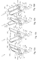
- the locking device 29 is in the Figures 16 to 17c shown in detail. In the Figure 17c the second pivot position 12b is shown. In the Figure 17b the third pivot position 12c. In the Figures 16 and 17a the first pivot position is shown. For reasons of clarity, the Figures 17a to 17c only a few particularly relevant reference symbols are shown.
- the locking device 29 comprises a first locking element 42 which can be brought into engagement with at least one further locking element 46 of the bearing axis 22.
- a further locking element 46 of the bearing axis 22 is assigned to each pivot position 12a, 12b, 12c of the at least one frame element 2, 2a, 2b.
- the locking device 29 comprises an operating element 39, by means of which the first locking element 42 can be displaced. By shifting the first locking element 42, the engagement with the at least one further locking element 46 of the mounting axis 22 can be released.
- the locking device 29 comprises a holding element 38, by means of which the locking device 29 is attached to the at least one frame element 2, 2a, 2b, preferably on a lower side of the at least one frame element 2, 2a, 2b along the height direction Z ', preferably on the lower section 7 of the at least one frame element 2, 2a, 2b is arranged.
- the holding element 38 is fastened to the frame element 2, 2a, 2b by means of a clip connection.
- the operating element 39 is arranged on the holding element 38, bearing elements 40 being provided between the holding element 38 and the operating element 39.
- the operating element 39 is attached pivotably to the first locking element 42 by means of an axis 41 and can thus be rocked.
- the storage elements 40 are guided in a guide 38e of the holding element 38.
- the first locking element 42 is designed like a pin or in the form of a bolt.
- a resetting device 43 is provided in the form of a compression spring element. This is actuated or compressed during the displacement movement to release the engagement.
- the first locking element 42 can be displaced by the restoring device 43, whereby an engagement with the at least one further locking element 46 of the bearing axis 22 is made possible.
- the restoring device or compression spring 43 is arranged between the locking element 42 and the holding element 38.
- the first locking element 42 has a radially outwardly projecting collar on which the compression spring rests. The locking element 42 is thus acted upon by a spring force which presses the locking element 42 radially inward.
- the locking element 42 engages in a further locking element 46 of the mounting axis 22 configured as a recess or bore.
- a plurality of recesses 46 are preferably provided.
- These recesses 46 are in the outer region 34 of the lateral surface 33 is arranged along the circumferential direction of the bearing axis 22.
- Three recesses 46 are advantageously provided.
- the arrangement of the recesses 46 is provided in such a way that, in the predetermined pivot positions 12a, 12b, 12c, the locking element 42 can engage in a recess 46 that is respectively assigned to the pivot position.
- the first locking element 42 protrudes through an opening 38a of the holding element 38, which is bordered by an outwardly extending, raised collar 38b.
- the resetting device rests on the inside against the raised collar 38b.
- Two support sections 39a, 39b each rest on this collar 38b.
- the first support section 39a is opposite the second support section 39b along a circumferential direction 44.
- the operating element 39 each comprises two operating sections 39c, 39d.
- the first operating section 39c is opposite the second operating section 39d along a circumferential direction 44.
- the operating sections 39c, 39d are located further outward along the circumferential direction 44 and along a radial direction 45.
- one of the operating sections 39c, 39d is pressed inward in the radial direction 45.
- the respective operating section 39c, 39d can thus be moved into a respective exception area 38c, 38d of the holding element 38.
- a rest position is shown in which the at least one frame element 2, 2a, 2b is in the first pivot position 12a.
- the respective further stop element 32a, 32b of the through-channel 24 is located essentially centrally along a fictitious circular arc 47a, 47b of the first 30 and second stop element 31, respectively.
- the fictitious circular arc 47a, 47b extends between the first stop surface 30b, 31b and the second Stop surface 30c, 31c.
- the first locking element 42 engages in the central recess 46 on the outer region 34 and thus locks this first pivot position 12a.
- the at least one frame element 2, 2a, 2b is generally essentially perpendicular to the first fictitious plane 13 and is therefore in a stowed position.
- Figure 17a is in two views the at least one frame element 2, 2a, 2b shown in the first pivot position 12a.
- the first operating section 39c of the operating element 39 has been actuated and thus shifted radially inward into the first recess area 38c of the holding element 38.
- the second operating section 39d has been actuated and thus displaced radially inward into the second recess area 38d of the holding element 38.
- the at least one frame element 2, 2a, 2b can be pivoted into the desired pivoting position.
- the at least one frame element 2, 2a, 2b is in the second pivot position 12b.
- the first further stop element 32a of the at least one frame element 2, 2a, 2b rests on the first stop surface 30a of the first stop element 30.
- the second further stop element 32b of the at least one frame element 2, 2a, 2b rests on the second stop surface 31b of the second stop element 31.
- the forces acting on the at least one frame element 2, 2a, 2b by the user are passed through these stops 30a, 31b from the at least one frame element 2, 2a, 2b into the mounting axis 22 and thus into the fastening element 5.
- the at least one frame element 2, 2a, 2b is locked in this pivot position 12b, since the first locking element 42 of the locking device 29 engages in the corresponding recess 46, which is assigned to this pivot position 12b, on the mounting axis 22.
- the at least one frame element 2, 2a, 2b is in the third pivot position 12c.
- the first further stop element 32a of the at least one frame element 2, 2a, 2b rests on the second stop surface 30b of the first stop element 30.
- the second further stop element 32b of the at least one frame element 2, 2a, 2b rests on the first stop surface 31a of the second stop element 31.
- the forces acting on the at least one frame element 2, 2a, 2b by the user are passed through these stops 30b, 31a from the at least one frame element 2, 2a, 2b into the mounting axis 22 and thus into the fastening element 5.
- the at least one frame element 2, 2a, 2b is locked in this pivot position 12c, since the locking element 42 of the first locking device 29 engages in the corresponding recess 46, which is assigned to this pivot position 12c, on the mounting axis 22.
- the angles of inclination ⁇ , ⁇ are predetermined by the length of the fictitious circular arcs 47a, 47b.
- the operating element 39 is arranged at a different position of the at least one frame element 2, 2a, 2b.
- the operating element 39 could, for example, also be arranged on the upper section 8 of the at least one frame element 2, 2a, 2b.
- a handle element 16 could be provided, which on the upper section 8 is arranged.
- the operating element 39 could be integrated in the grip element 16. In such a configuration, the mode of operation described at the beginning for actuating the first locking element 42 can be retained.
- the (lever) force described above, which acts on the axle 41, could be transmitted from the operating element 39 to the axle 41 by means of a transmission device.
- a transmission device Such a (mechanical) transmission device could, for example, be a Bowden cable, an actuating rod or transmission device by means of toothed wheels.
- These transmission devices can preferably be arranged in or on the at least one frame element 2, 2a, 2b.
- the transmission device transmits electrical signals which control an actuator. The actuator then actuates the locking element 42.
- a seat cover 18 is arranged on or in the at least one frame element 2, 2a, 2b.
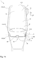
- the seat cover 18 is in or above the inner surface 28, which is enclosed by the frame element 2, 2a, 2b, or the upper section 8 and the lower section 7. If the at least one frame element 2, 2a, 2b is designed in one piece or in one piece, the seat cover 18 can be designed like a hose. Accordingly, a section of the tubular seat cover 18 could advantageously be arranged on each side above the inner surface 28. This is for example in the Figures 18a and 18b recognizable.
- the hose-like seat cover 18 comprises a first opening side 48a, which is upper along the height axis Z ', which is preferably closed by means of a seam and rests against the third transverse section 11.
- the tubular seat cover 18 comprises a second opening side 48b, which is lower along the height axis Z ′, which is preferably closed by means of an openable closure and lies on or on the lower section 7.
- a flat seat cover 18 can be used. This is in the Figures 1a to 2b and 5 to 12d indicated.
- the seat cover 18 is connected at the edge from bottom to top with the at least one frame element 2, 2a, 2b.
- the seat cover 18 is connected to the two strut elements 27 and the third transverse section 11.
- a welt rail can be arranged on the inside of the two strut elements 27 and the third transverse section 11.
- the welt rail is provided on an inner side of the at least one frame element 2, 2a, 2b and thus faces the inner surface 28.
- the seat cover 18 has a welt flap which is arranged or clamped in the welt rail.
- the seat cover 18 is advantageously a knitted fabric.
- a knitted fabric is advantageously produced with a knitting machine.
- This advantageous use of a knitted fabric allows a high degree of variability in the design of the areas with different elasticities.
- Such knitted fabrics which have both flexible and rigid or solid sections, can be produced very easily and inexpensively compared to woven fabrics.
- the knitted fabric is advantageously produced using a 3D knitting process. Such an advantageous technique allows both flexible and rigid areas to be incorporated within a knitted part.
- the seat cover 18 has at least two areas 19, 20 which have different elasticities.
- a first area 19 has a lower elasticity than the second area 20.
- the second area 20 can be elastically deformed by the action of a force.
- the first area 19 is arranged above the second area 20 along the height axis Z ′. Such a first area 19 can thus be provided and suitable for supporting a shoulder area of the user.
- the second region 20, which has a higher elasticity, can then be arranged in or above a central and / or lower section of the inner surface 28 along the height axis Z ′. Such a second area 20 can be provided and suitable for supporting the lower back and the gluteal region of the user. It would of course also be conceivable to provide further areas with different elasticities in the seat cover.
- the seat cover 18 is connected to the at least one frame element 2, 2a, 2b at the edge from bottom to top. As a result of the action of force, the second region 20 forms a three-dimensional deformation 21 or bulge.
- the seat cover 18 can have a third area 49 which is arranged along the height axis Z 'below the second area.
- This third area 49 can be connected to the at least one frame element 2, 2a, 2b by means of a preferably detachable connection.
- the third area 49 can be arranged on the first 9 and the second transverse section 10 and serve as seat padding. This is for example in the Figures 18a and 18b shown.
- the seat cover 18 can also have a space or recess 50.
- the third area 49 and the second area 19 are therefore only connected via web-like sections which are arranged on the strut elements 27 of the at least one frame element 2, 2a, 2b.
- the second area 19 merges into the third area 49 without interruption. This is for example in the Figure 5 shown.
- the seat area 4, 4a, 4b can be further enlarged if at least one additional element 17 is provided, which is arranged on the lower section 7 of the at least one frame element 2, 2a, 2b.
- the additional element 17 increases the depth of the seat area 4, 4a, 4b.
- the additional element 17 can be arranged on the upper surfaces of the first and / or second transverse section or can be arranged adjacent to the upper surfaces of the first and / or second transverse section.
- Such an additional element is indicated in FIG. 3 and can be attached to the frame element 2, 2a, 2b by means of a force-fit and / or form-fitting connection. Possible connections are clip connections, screw connections, plug connections, etc.
- the additional element 17 can also be provided for fixing the seat cover 18.
- the effective seat area advantageously comprises the first or second seat area 4a, 4b and is preferably oriented essentially horizontally or parallel to the first fictitious plane 13.
- This effective seat surface is made available by the first or second seat area depending on the pivot position 12b, 12c.
- the effective seat surface can be provided at least in sections by the upper surface of the first transverse section 9 or the upper surface of the second transverse section 10.
- further elements, further layers, covers, upholstery, etc. to be arranged on the upper surfaces of the transverse sections 9, 10, which then at least in sections form the effective seat surface.
- the additional element 17 can also increase the effective seating area.
- the effective seat surface can preferably be formed at least in sections by the additional element 17. However, it would also be conceivable that further layers, covers, upholstery, etc. are arranged on the additional element 17, which then form the effective seat surface at least in sections.
- An effective seat area advantageously comprises the first or second seat area 4a, 4b of the at least one frame element 2, 2a, 2b and a portion of the second area 20 of the seat cover 18. The effective seat area can also form the transition between the third 49 and the second area 19 of the Seat cover 18 include.
- At least one grip element 16 is furthermore arranged on at least one strut element 27 or the upper section 8 on the at least one frame element.
- the grip element is arranged on an outside of the seat arrangement 1, which is located on a passage of the means of transport. If two passages are provided, a grip element 16 can of course also be provided on each outer side of the seat arrangement 1.
- the fastening device 5 comprises two fastening elements 25 in the form of arm elements 25a, 25b, which extend along the height axis Z and open into a base element 26. Starting from the base element 26, the arm elements 25a, 25b likewise extend along the width axis Y, so that they run obliquely upward. A distance 53 between the first arm element 25a and the second arm element 25b decreases along the height axis Z downwards. At an upper end, the arm elements 25, 25a, 25b each have the receiving devices 23, 23a, 23b for the bearing axis 22.
- the receiving devices 23, 23a, 23b can be designed in one piece, in one piece or in several pieces with the arm element.
- the arm elements 25, 25a, 25b are advantageously oriented essentially parallel to the height axis Z.
- the arm elements 25, 25a, 25b can be designed as a flat profile. In this flat profile, a preferably circular recess can form the receiving devices 23, 23a, 23b.
- the receiving devices 23, 23a, 23b can be designed essentially cylindrical with a preferably circular cross section.
- the base element 26 has a smaller extension along the width axis Y than the mounting axis 22 or than the distance between the receiving devices 23, 23a, 23b.
- a cover element 51 is provided on each side of the receiving device 23, 23a, 23b.
- the arm elements can run essentially in a straight line or in a V-shape, as in FIG Figures 1a to 2b and 4 shown.
- an approximately S-shaped profile of the arm elements 25, 25a, 25b is also conceivable.
- the base element 26 is either fastened directly to the floor 102 of the transport means 101 or is arranged on the base 102 of the transport means 101 such that it can be displaced via a guide device.
- Such a configuration has the advantage that the base element is arranged centrally under the at least one frame element 2, 2a, 2b. A symmetrical introduction of force into the base element 26 can thus take place.
- a fastening element 5 is provided which has a lower height.
- the base element 26 is designed merely as a cross strut extending along the width axis Y.
- Such seating arrangements 1 could for example be used by the elderly or children.
- a seat arrangement 1 is shown with a seat height for adults.
- the base element 26 is designed as a substantially rectangular element which comprises two cross struts extending along the width axis Y.
- the upper cross strut along the height axis Z is used as a footrest 52 planned.
- a rotating device it would also be conceivable for a rotating device to be arranged or integrated on or in the base element 26.
- the fastening device 5 or the seat arrangement 1 could then be rotated about an axis of rotation 54 which runs parallel to the height axis Z. This is in the Figures 1b, 2b and 3 indicated by the double arrow 55.
- the embodiments according to Figures 5 to 13 show a seat arrangement 1 with two frame elements 2, 2a, 2b which are arranged on the fastening device 5.
- the two frame elements 2, 2a, 2b are arranged next to one another along the width axis Y.
- the two frame elements 2, 2a, 2b are independent of one another, about a common pivot axis 6 extending along a width axis Y relative to the fastening device 5 by the angles of inclination ⁇ , ⁇ in the first, second and third pivot positions 12a, 12b, 12c pivotable.
- the fastening device 5 can be designed in different ways.
- a mounting axis 22 is provided which extends along the seat arrangement and extends through the respective through channels 24 of the two frame elements 2, 2a, 2b. As already described, such a through channel 24 can extend essentially over the entire width of a frame element 2, 2a, 2b. An only partial extension would also be conceivable.
- a locking device 29 is also provided on each of the two frame elements 2, 2, 2a, 2b. The bearing axis 22 is received in two receiving devices 23, 23a, 23b of the fastening device 5.
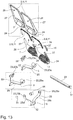
- FIG. 13 is an exploded view of the seat assembly analogous to FIG Figure 4 shown. However, in the Figure 13 only 3 possible configurations of the fastening device 5 are shown. Of course, the other fastening devices 5 shown in FIG Figure 13 inserted.
- At least one cover element 51 can also be provided to close off the bearing axis 22.
- the bearing axis 22 is received in at least two receiving devices 23, 23a, 23b of the fastening device 5.
- Each of the receiving devices 23, 23a, 23b is arranged on a fastening element 25.
- a first receiving device 23a is arranged between the first frame element 2a and the second frame element 2b.
- a further second receiving device 23b is arranged to the side of one of the two frame elements 2a, 2b, or on one of the two outer sides of the seat arrangement 1.
- the two receiving devices 23, 23a, 23b are essentially cylindrical in shape with an essentially circular cross-section.
- a second receiving device 23b is arranged on a fastening element 25 in the form of a plate-like first element 56, which can be fastened to a wall element of the means of transport 101.
- the first plate-like element 56 is accordingly in a fastening plane 58 (see FIG Figure 6c ), which extends essentially parallel to the second fictitious plane 14.
- the wall element of the means of transport 101 advantageously comprises the fastening plane 58.
- the first receiving device 23a is arranged on a fastening element 25 in the form of an arm element 25. This arm element 25 is designed as a cantilever arm or cantilever.
- the arm element 25 accordingly extends from the first receiving device 23a to the fastening plane 58 and opens into a second plate-like element 57, which is also arranged in the fastening plane 58 and can be arranged on the wall element of the means of transport.
- a lower protruding section of the arm element 25 extends obliquely along the height axis Z upwards.
- the lower protruding section forms an angle with the first fictitious plane 13, which is in a range between 10 ° and 45 °.
- An upper section of the arm element 25 adjoining the lower section forms an angle with the first fictitious plane 13 which is in a range between 45 ° and 90 °.
- Figure 3 shows a perspective view of this embodiment.
- Figure 6a shows a front view and Figure 6b a rear view of this embodiment.
- Figure 6c Fig. 3 is a side view and Fig Figure 6d a view from below of this embodiment is shown.
- the embodiment according to Figures 11a to 11d is analogous to the embodiment according to FIGS Figures 5 to 6d .
- the only difference is that only one plate-like element 59 is provided.
- This third plate-like element 59 also extends in the fastening plane 58.
- the second receiving device 23b is arranged on this third plate-like element 59.
- the arm element 25 likewise opens into the third plate-like element 59.
- two fastening elements 25 are provided in the form of arm elements 25a, 25b on which the receiving devices 23, 23a, 23b are arranged or integrated.
- Figure 7 a perspective view of a first embodiment.
- Figure 8a shows a front view and Figure 8b a rear view of this first embodiment.
- Figure 8c Fig. 3 is a side view and Fig Figure 8d a view from below of this first embodiment is shown.
- Figure 9 Figure 3 shows a perspective view of a second embodiment.
- Figure 10a shows a front view and Figure 10b a rear view of this second embodiment.
- Figure 10c is a side view and in Figure 10d a view from below of this second embodiment is shown.
- Both arm elements 25, 25a, 25b are designed as flat profiles and can be fixed to the floor of the means of transport 101.
- a fastening area 60 is formed on the respective arm element 25, 25a, 25b, which has a section parallel to the floor of the means of transport. In this section, bores can be provided, by means of which the fastening is made possible, for example by a screw connection.
- the two arm elements 25, 25a, 25b are inclined with respect to a reference axis 61 which runs perpendicular to the fictitious first plane 13. An angle of inclination ⁇ can thus be defined between this reference axis 61 and a central axis 62 of the arm elements 25, 25a, 25b.
- the angle of inclination ⁇ is in a range between 5 ° and 20 °, preferably in a range between 10 ° and 15 °.
- the second receiving device 23b and the second arm element 25b connected to it are advantageously provided on an outside of the seat arrangement 1, on which a grip element 16 is also provided on the corresponding frame element 2, 2a, 2b.
- the seat arrangement 1 accordingly has an advantageously increased stability on the outside of the seat arrangement 1.
- the arm elements 25, 25a, 25b and the associated receiving devices 23, 23a, 23b can be designed in one piece, in one piece or in several pieces.
- the through channels 24 can likewise extend essentially over the entire width of the frame element 2, 2a, 2b or only in sections. In FIG. 8d it can be seen, for example, that the through channel 24 extends only in sections along the width direction Y ′.
- the two receiving devices 23, 23a, 23b here comprise an extension element 63 which extends along the width direction Y 'of the frame elements 2, 2a, 2b.
- the receiving devices 23, 23a, 23b and the corresponding extension element 63 can be designed in one piece, in one piece or in several pieces.
- the extension element belonging to the first receiving device 23a extends, starting from the intermediate space existing between the frame elements 2, 2a, 2b, along the second frame element 2b.
- the extension element belonging to the first receiving device 23a extends from the outside to the intermediate space existing between the frame elements 2, 2a, 2b along the first frame element 2a.
- the through channel 24 extends according to the embodiment according to FIG Figure 10d over a substantial portion of the width direction of the frame members 2, 2a, 2b.
- a substantial section is to be understood as meaning at least half, preferably three quarters, of the entire width extension of the frame element 2, 2a, 2b.
- a footrest 52 or a footrest element is provided on each arm element 25, 25a, 25b. Starting from the respective arm element 25, 25a, 25b, this footrest 52 extends essentially parallel to the first fictitious plane 13 or the floor of the means of transport.
- the first receiving devices 23, 23a and the second receiving devices 23, 23a, 23b of the fastening device 5 are arranged on the outer sides of the seat arrangement 1.
- the two frame elements 2, 2a, 2b are thus arranged between the receiving devices 23, 23a, 23b.
- Only a preferably sleeve-shaped spacer element 64 is provided between the two frame elements 2, 2a, 2b.
- This fastening device 5 is analogous to the fastening device according to FIGS Figures 2a and 2b educated. The corresponding description is therefore analogous.
- the two S-shaped or V-shaped fastening elements 25 in the form of arm elements 25a, 25b also terminate in a base element 26.
- a rotating device can be provided analogously, by means of which the seat arrangement 1 can be rotated about an axis of rotation 54.
- an interior device 100 for a means of transport 101 is shown.
- This interior arrangement 100 comprises a plurality of seat arrangements 1.
- These seat arrangements 1 are fixedly fixed on the floor of the means of transport 101 or are guided in a guide system (not shown).
- This guide system can be, for example, a rail device and is preferably arranged on the floor of the means of transport 101.
- a guide system could be provided on a wall element of the means of transport 101.
- a certain number of seat arrangements 1 could thus initially be stored in a stowage area 103 of the means of transport 101.
- the required number of seat arrangements 1 can be distributed from the stowage area 103 along the guide system 102 in the interior of the means of transport 101. This can be done manually or by an actuator.
- These seats should be modifiable for different needs. Such needs are, for example, the adjustment of the seat orientation with respect to the direction of travel or the adjustment of seating groups facing one another. If there is luggage or bulky luggage, fewer seat arrangements 1 can accordingly be removed from the stowage area. Such an interior arrangement 100 with the seat arrangements 1 can provide more than 25% more seats compared to a previous one with seating arrangements.
- the first pivot position 12a i.e. the upright orientation, take the seat arrangements 1 along the depth axis X only the depth of the seat section 4 of the frame element 2, 2a, 2b.
- the seat arrangements 1 can therefore be stored in an extremely space-saving manner.
- the seat arrangements 1 take up considerably less space in a depth direction X.
- the space required in the depth direction is determined by the angle of inclination ⁇ , ⁇ and the required foot space.
- the user assumes a sitting posture which approximately corresponds to a standing posture.
- this sitting posture requires significantly less space than the classic sitting posture, in which the legs are angled approximately at right angles.
- the seat arrangements 1 advantageously enable extremely convenient adjustment of the seat orientation due to their pivotability. This also allows seating groups to be easily modified. This is for example in Figure 19 shown.
- the seat arrangements 1 each have two frame elements 2, 2a, 2b.
- a first seating group 104 is a group of four.
- the two frame elements 2, 2a, 2b of two consecutive seat arrangements 1 are inclined in such a way that two users each face one another.
- a second group of seats 105 is a group of three.
- a frame element 2a is aligned in such a way that the user faces a seat arrangement with two frame elements 2a, 2b.
- the rest of the frame element 2b is used as a single space 106.
- the seating arrangement 1 is used as a two-seater seat.
- both frame elements 2a, 2b are inclined or aligned in the same direction.
Landscapes
- Engineering & Computer Science (AREA)
- Mechanical Engineering (AREA)
- Aviation & Aerospace Engineering (AREA)
- Transportation (AREA)
- Seats For Vehicles (AREA)
Applications Claiming Priority (5)
| Application Number | Priority Date | Filing Date | Title |
|---|---|---|---|
| DE102019124895 | 2019-09-16 | ||
| DE102019124898 | 2019-09-16 | ||
| DE102019124901 | 2019-09-16 | ||
| DE102019124897 | 2019-09-16 | ||
| DE102020109160.5A DE102020109160B4 (de) | 2019-09-16 | 2020-04-02 | Sitzanordnung für ein Transportmittel |
Publications (2)
| Publication Number | Publication Date |
|---|---|
| EP3792101A1 true EP3792101A1 (fr) | 2021-03-17 |
| EP3792101B1 EP3792101B1 (fr) | 2023-05-17 |
Family
ID=72234772
Family Applications (1)
| Application Number | Title | Priority Date | Filing Date |
|---|---|---|---|
| EP20192494.1A Active EP3792101B1 (fr) | 2019-09-16 | 2020-08-24 | Agencement des sièges pour un moyen de transport |
Country Status (2)
| Country | Link |
|---|---|
| US (1) | US11285845B2 (fr) |
| EP (1) | EP3792101B1 (fr) |
Cited By (1)
| Publication number | Priority date | Publication date | Assignee | Title |
|---|---|---|---|---|
| DE102022201545A1 (de) | 2022-02-15 | 2023-08-17 | Siemens Mobility GmbH | Sitzeinheit und Fahrzeug mit Sitzeinheit |
Families Citing this family (4)
| Publication number | Priority date | Publication date | Assignee | Title |
|---|---|---|---|---|
| EP3792100B1 (fr) | 2019-09-16 | 2024-04-03 | Grammer Ag | Agencement de sièges pour un moyen de transport |
| DE102020109160B4 (de) | 2019-09-16 | 2026-05-07 | Grammer Aktiengesellschaft | Sitzanordnung für ein Transportmittel |
| WO2025075612A1 (fr) * | 2023-10-04 | 2025-04-10 | Safran Seats Usa Llc | Pied incliné pour ensemble siège de passager |
| KR20250089663A (ko) * | 2023-12-12 | 2025-06-19 | 현대자동차주식회사 | 회전 메커니즘 및 이를 포함하는 시트 |
Citations (3)
| Publication number | Priority date | Publication date | Assignee | Title |
|---|---|---|---|---|
| US5364151A (en) * | 1993-04-21 | 1994-11-15 | Mack Trucks, Inc. | Adjustable seat apparatus for utility vehicle |
| JPH08131295A (ja) * | 1994-11-12 | 1996-05-28 | Tenryu Ind Co Ltd | 立姿勢用シート |
| DE102007038829A1 (de) * | 2007-08-16 | 2009-02-19 | Stefan Zoell | Vorrichtung zur Körperunterstützung und Verwendung der Vorrichtung in unterschiedlichen Tätigkeitsbereichen eines Benutzers |
Family Cites Families (8)
| Publication number | Priority date | Publication date | Assignee | Title |
|---|---|---|---|---|
| US3762764A (en) * | 1972-02-22 | 1973-10-02 | Rohr Industries Inc | Folding seat for transportation type vehicle |
| FR2569964B1 (fr) * | 1984-09-10 | 1987-01-09 | Gianni Vianello | Appui ischiatique |
| US5463972A (en) * | 1993-12-01 | 1995-11-07 | Stidd Systems, Inc. | High-performance seating/support system |
| DE102010000259A1 (de) | 2010-01-29 | 2011-08-04 | Benecke-Kaliko AG, 30419 | Mehrschichtiges Flächengebilde |
| US8220872B2 (en) * | 2011-12-14 | 2012-07-17 | Simon Yeonjun Hong | Sit-stand chair |
| FR3040030B1 (fr) * | 2015-08-14 | 2018-12-07 | Alstom Transp Tech | Dispositif de confort, notamment pour un passager de vehicule de transport public |
| DE102016202089A1 (de) | 2016-02-11 | 2017-08-17 | Siemens Aktiengesellschaft | Fahrzeug, insbesondere Schienenfahrzeug, mit zumindest einem Sitz |
| DE102017008684A1 (de) | 2016-09-20 | 2018-03-22 | Siemens Aktiengesellschaft | Schienengebundenes Transportmittel |
-
2020
- 2020-08-24 EP EP20192494.1A patent/EP3792101B1/fr active Active
- 2020-09-15 US US17/020,996 patent/US11285845B2/en active Active
Patent Citations (3)
| Publication number | Priority date | Publication date | Assignee | Title |
|---|---|---|---|---|
| US5364151A (en) * | 1993-04-21 | 1994-11-15 | Mack Trucks, Inc. | Adjustable seat apparatus for utility vehicle |
| JPH08131295A (ja) * | 1994-11-12 | 1996-05-28 | Tenryu Ind Co Ltd | 立姿勢用シート |
| DE102007038829A1 (de) * | 2007-08-16 | 2009-02-19 | Stefan Zoell | Vorrichtung zur Körperunterstützung und Verwendung der Vorrichtung in unterschiedlichen Tätigkeitsbereichen eines Benutzers |
Cited By (2)
| Publication number | Priority date | Publication date | Assignee | Title |
|---|---|---|---|---|
| DE102022201545A1 (de) | 2022-02-15 | 2023-08-17 | Siemens Mobility GmbH | Sitzeinheit und Fahrzeug mit Sitzeinheit |
| DE102022201545B4 (de) | 2022-02-15 | 2024-05-02 | Siemens Mobility GmbH | Sitzeinheit und Fahrzeug mit Sitzeinheit |
Also Published As
| Publication number | Publication date |
|---|---|
| EP3792101B1 (fr) | 2023-05-17 |
| US20210078613A1 (en) | 2021-03-18 |
| US11285845B2 (en) | 2022-03-29 |
Similar Documents
| Publication | Publication Date | Title |
|---|---|---|
| EP3792101B1 (fr) | Agencement des sièges pour un moyen de transport | |
| DE102020109160B4 (de) | Sitzanordnung für ein Transportmittel | |
| DE3800754C2 (fr) | ||
| EP3848237B1 (fr) | Agencement de siège pour un moyen de transport | |
| DE102014107816B4 (de) | Nutzfahrzeugsitz mit arretierbarem Querschlittenteil | |
| WO2017012990A1 (fr) | Siège de véhicule, en particulier siège de véhicule à moteur | |
| DE4301811B4 (de) | Rückenlehnengelenk für einen Fahrzeugsitz mit einem Sitzträger und einer an diesem angelenkten Rückenlehne | |
| EP2605932A1 (fr) | Siège de véhicule automobile comprenant plusieurs ferrures | |
| DE69700556T2 (de) | Nach vorn bewegbarer Fahrzeugsitz, um zu einem hinteren Raum zu gelangen | |
| WO2020058260A1 (fr) | Dispositif de siège et véhicule | |
| EP3792102B1 (fr) | Agencement des sièges pour un moyen de transport | |
| DE3329725C2 (fr) | ||
| EP0602361B1 (fr) | Articulation de dossier pour un siège de véhicule | |
| DE102012004695A1 (de) | Verriegelungseinrichtung, Verstellvorrichtung, Kraftfahrzeugsitz, Kraftfahr-zeug sowie Verfahren hierzu | |
| DE69403860T2 (de) | Omnibussitz | |
| WO2014125055A1 (fr) | Siège de véhicule, en particulier pour une rangée de sièges arrière | |
| DE10157516B4 (de) | Kraftfahrzeug-Sitz | |
| EP3792099B1 (fr) | Agencement des sièges pour un moyen de transport | |
| DE68902087T2 (de) | Sitz mit verstellbarer und umlenkbarer rueckenlehne. | |
| DE4414608C2 (de) | Fahrzeugsitz, insbesondere Kraftfahrzeug-Rücksitz | |
| DE20121469U1 (de) | Kraftfahrzeug-Frontsitz mit längsverstellbarem Sitzteil | |
| DE19738867A1 (de) | Sitz für ein Fahrzeug mit einem Kindersitz | |
| DE202015106679U1 (de) | Verstellbare Sitz- und/oder Liegemöbelanordnung sowie Möbelbeschlag für eine solche Sitz- und/oder Liegemöbelanordnung | |
| DE20004346U1 (de) | Trägereinrichtung zur verstellbaren Halterung eines Fahrzeugsitzes | |
| DE102013221929B4 (de) | Fahrzeugsitz mit einem Beschlag mit Easy-Entry-Funktion |
Legal Events
| Date | Code | Title | Description |
|---|---|---|---|
| PUAI | Public reference made under article 153(3) epc to a published international application that has entered the european phase |
Free format text: ORIGINAL CODE: 0009012 |
|
| STAA | Information on the status of an ep patent application or granted ep patent |
Free format text: STATUS: THE APPLICATION HAS BEEN PUBLISHED |
|
| AK | Designated contracting states |
Kind code of ref document: A1 Designated state(s): AL AT BE BG CH CY CZ DE DK EE ES FI FR GB GR HR HU IE IS IT LI LT LU LV MC MK MT NL NO PL PT RO RS SE SI SK SM TR |
|
| AX | Request for extension of the european patent |
Extension state: BA ME |
|
| STAA | Information on the status of an ep patent application or granted ep patent |
Free format text: STATUS: REQUEST FOR EXAMINATION WAS MADE |
|
| 17P | Request for examination filed |
Effective date: 20210520 |
|
| RBV | Designated contracting states (corrected) |
Designated state(s): AL AT BE BG CH CY CZ DE DK EE ES FI FR GB GR HR HU IE IS IT LI LT LU LV MC MK MT NL NO PL PT RO RS SE SI SK SM TR |
|
| RIC1 | Information provided on ipc code assigned before grant |
Ipc: B60N 2/70 20060101ALI20221208BHEP Ipc: B60N 2/68 20060101ALI20221208BHEP Ipc: B60N 2/20 20060101ALI20221208BHEP Ipc: B60N 2/24 20060101ALI20221208BHEP Ipc: B64D 11/06 20060101ALI20221208BHEP Ipc: B61D 33/00 20060101ALI20221208BHEP Ipc: B61D 1/04 20060101ALI20221208BHEP Ipc: B60N 2/22 20060101ALI20221208BHEP Ipc: B60N 2/015 20060101ALI20221208BHEP Ipc: B60N 2/01 20060101AFI20221208BHEP |
|
| GRAP | Despatch of communication of intention to grant a patent |
Free format text: ORIGINAL CODE: EPIDOSNIGR1 |
|
| STAA | Information on the status of an ep patent application or granted ep patent |
Free format text: STATUS: GRANT OF PATENT IS INTENDED |
|
| INTG | Intention to grant announced |
Effective date: 20230120 |
|
| GRAS | Grant fee paid |
Free format text: ORIGINAL CODE: EPIDOSNIGR3 |
|
| GRAA | (expected) grant |
Free format text: ORIGINAL CODE: 0009210 |
|
| STAA | Information on the status of an ep patent application or granted ep patent |
Free format text: STATUS: THE PATENT HAS BEEN GRANTED |
|
| AK | Designated contracting states |
Kind code of ref document: B1 Designated state(s): AL AT BE BG CH CY CZ DE DK EE ES FI FR GB GR HR HU IE IS IT LI LT LU LV MC MK MT NL NO PL PT RO RS SE SI SK SM TR |
|
| REG | Reference to a national code |
Ref country code: GB Ref legal event code: FG4D Free format text: NOT ENGLISH |
|
| REG | Reference to a national code |
Ref country code: CH Ref legal event code: EP |
|
| REG | Reference to a national code |
Ref country code: DE Ref legal event code: R096 Ref document number: 502020003286 Country of ref document: DE |
|
| REG | Reference to a national code |
Ref country code: IE Ref legal event code: FG4D Free format text: LANGUAGE OF EP DOCUMENT: GERMAN |
|
| REG | Reference to a national code |
Ref country code: AT Ref legal event code: REF Ref document number: 1568274 Country of ref document: AT Kind code of ref document: T Effective date: 20230615 |
|
| P01 | Opt-out of the competence of the unified patent court (upc) registered |
Effective date: 20230522 |
|
| REG | Reference to a national code |
Ref country code: LT Ref legal event code: MG9D |
|
| REG | Reference to a national code |
Ref country code: NL Ref legal event code: MP Effective date: 20230517 |
|
| PG25 | Lapsed in a contracting state [announced via postgrant information from national office to epo] |
Ref country code: SE Free format text: LAPSE BECAUSE OF FAILURE TO SUBMIT A TRANSLATION OF THE DESCRIPTION OR TO PAY THE FEE WITHIN THE PRESCRIBED TIME-LIMIT Effective date: 20230517 Ref country code: PT Free format text: LAPSE BECAUSE OF FAILURE TO SUBMIT A TRANSLATION OF THE DESCRIPTION OR TO PAY THE FEE WITHIN THE PRESCRIBED TIME-LIMIT Effective date: 20230918 Ref country code: NO Free format text: LAPSE BECAUSE OF FAILURE TO SUBMIT A TRANSLATION OF THE DESCRIPTION OR TO PAY THE FEE WITHIN THE PRESCRIBED TIME-LIMIT Effective date: 20230817 Ref country code: NL Free format text: LAPSE BECAUSE OF FAILURE TO SUBMIT A TRANSLATION OF THE DESCRIPTION OR TO PAY THE FEE WITHIN THE PRESCRIBED TIME-LIMIT Effective date: 20230517 Ref country code: ES Free format text: LAPSE BECAUSE OF FAILURE TO SUBMIT A TRANSLATION OF THE DESCRIPTION OR TO PAY THE FEE WITHIN THE PRESCRIBED TIME-LIMIT Effective date: 20230517 |
|
| PG25 | Lapsed in a contracting state [announced via postgrant information from national office to epo] |
Ref country code: RS Free format text: LAPSE BECAUSE OF FAILURE TO SUBMIT A TRANSLATION OF THE DESCRIPTION OR TO PAY THE FEE WITHIN THE PRESCRIBED TIME-LIMIT Effective date: 20230517 Ref country code: PL Free format text: LAPSE BECAUSE OF FAILURE TO SUBMIT A TRANSLATION OF THE DESCRIPTION OR TO PAY THE FEE WITHIN THE PRESCRIBED TIME-LIMIT Effective date: 20230517 Ref country code: LV Free format text: LAPSE BECAUSE OF FAILURE TO SUBMIT A TRANSLATION OF THE DESCRIPTION OR TO PAY THE FEE WITHIN THE PRESCRIBED TIME-LIMIT Effective date: 20230517 Ref country code: LT Free format text: LAPSE BECAUSE OF FAILURE TO SUBMIT A TRANSLATION OF THE DESCRIPTION OR TO PAY THE FEE WITHIN THE PRESCRIBED TIME-LIMIT Effective date: 20230517 Ref country code: IS Free format text: LAPSE BECAUSE OF FAILURE TO SUBMIT A TRANSLATION OF THE DESCRIPTION OR TO PAY THE FEE WITHIN THE PRESCRIBED TIME-LIMIT Effective date: 20230917 Ref country code: HR Free format text: LAPSE BECAUSE OF FAILURE TO SUBMIT A TRANSLATION OF THE DESCRIPTION OR TO PAY THE FEE WITHIN THE PRESCRIBED TIME-LIMIT Effective date: 20230517 Ref country code: GR Free format text: LAPSE BECAUSE OF FAILURE TO SUBMIT A TRANSLATION OF THE DESCRIPTION OR TO PAY THE FEE WITHIN THE PRESCRIBED TIME-LIMIT Effective date: 20230818 |
|
| PG25 | Lapsed in a contracting state [announced via postgrant information from national office to epo] |
Ref country code: FI Free format text: LAPSE BECAUSE OF FAILURE TO SUBMIT A TRANSLATION OF THE DESCRIPTION OR TO PAY THE FEE WITHIN THE PRESCRIBED TIME-LIMIT Effective date: 20230517 |
|
| PG25 | Lapsed in a contracting state [announced via postgrant information from national office to epo] |
Ref country code: SK Free format text: LAPSE BECAUSE OF FAILURE TO SUBMIT A TRANSLATION OF THE DESCRIPTION OR TO PAY THE FEE WITHIN THE PRESCRIBED TIME-LIMIT Effective date: 20230517 |
|
| PG25 | Lapsed in a contracting state [announced via postgrant information from national office to epo] |
Ref country code: SM Free format text: LAPSE BECAUSE OF FAILURE TO SUBMIT A TRANSLATION OF THE DESCRIPTION OR TO PAY THE FEE WITHIN THE PRESCRIBED TIME-LIMIT Effective date: 20230517 Ref country code: SK Free format text: LAPSE BECAUSE OF FAILURE TO SUBMIT A TRANSLATION OF THE DESCRIPTION OR TO PAY THE FEE WITHIN THE PRESCRIBED TIME-LIMIT Effective date: 20230517 Ref country code: RO Free format text: LAPSE BECAUSE OF FAILURE TO SUBMIT A TRANSLATION OF THE DESCRIPTION OR TO PAY THE FEE WITHIN THE PRESCRIBED TIME-LIMIT Effective date: 20230517 Ref country code: EE Free format text: LAPSE BECAUSE OF FAILURE TO SUBMIT A TRANSLATION OF THE DESCRIPTION OR TO PAY THE FEE WITHIN THE PRESCRIBED TIME-LIMIT Effective date: 20230517 Ref country code: DK Free format text: LAPSE BECAUSE OF FAILURE TO SUBMIT A TRANSLATION OF THE DESCRIPTION OR TO PAY THE FEE WITHIN THE PRESCRIBED TIME-LIMIT Effective date: 20230517 Ref country code: CZ Free format text: LAPSE BECAUSE OF FAILURE TO SUBMIT A TRANSLATION OF THE DESCRIPTION OR TO PAY THE FEE WITHIN THE PRESCRIBED TIME-LIMIT Effective date: 20230517 |
|
| REG | Reference to a national code |
Ref country code: DE Ref legal event code: R097 Ref document number: 502020003286 Country of ref document: DE |
|
| PG25 | Lapsed in a contracting state [announced via postgrant information from national office to epo] |
Ref country code: MC Free format text: LAPSE BECAUSE OF FAILURE TO SUBMIT A TRANSLATION OF THE DESCRIPTION OR TO PAY THE FEE WITHIN THE PRESCRIBED TIME-LIMIT Effective date: 20230517 |
|
| PLBE | No opposition filed within time limit |
Free format text: ORIGINAL CODE: 0009261 |
|
| STAA | Information on the status of an ep patent application or granted ep patent |
Free format text: STATUS: NO OPPOSITION FILED WITHIN TIME LIMIT |
|
| REG | Reference to a national code |
Ref country code: CH Ref legal event code: PL |
|
| PG25 | Lapsed in a contracting state [announced via postgrant information from national office to epo] |
Ref country code: MC Free format text: LAPSE BECAUSE OF FAILURE TO SUBMIT A TRANSLATION OF THE DESCRIPTION OR TO PAY THE FEE WITHIN THE PRESCRIBED TIME-LIMIT Effective date: 20230517 |
|
| PG25 | Lapsed in a contracting state [announced via postgrant information from national office to epo] |
Ref country code: LU Free format text: LAPSE BECAUSE OF NON-PAYMENT OF DUE FEES Effective date: 20230824 |
|
| 26N | No opposition filed |
Effective date: 20240220 |
|
| PG25 | Lapsed in a contracting state [announced via postgrant information from national office to epo] |
Ref country code: LU Free format text: LAPSE BECAUSE OF NON-PAYMENT OF DUE FEES Effective date: 20230824 Ref country code: CH Free format text: LAPSE BECAUSE OF NON-PAYMENT OF DUE FEES Effective date: 20230831 |
|
| PG25 | Lapsed in a contracting state [announced via postgrant information from national office to epo] |
Ref country code: SI Free format text: LAPSE BECAUSE OF FAILURE TO SUBMIT A TRANSLATION OF THE DESCRIPTION OR TO PAY THE FEE WITHIN THE PRESCRIBED TIME-LIMIT Effective date: 20230517 |
|
| REG | Reference to a national code |
Ref country code: BE Ref legal event code: MM Effective date: 20230831 |
|
| REG | Reference to a national code |
Ref country code: IE Ref legal event code: MM4A |
|
| PG25 | Lapsed in a contracting state [announced via postgrant information from national office to epo] |
Ref country code: SI Free format text: LAPSE BECAUSE OF FAILURE TO SUBMIT A TRANSLATION OF THE DESCRIPTION OR TO PAY THE FEE WITHIN THE PRESCRIBED TIME-LIMIT Effective date: 20230517 |
|
| PG25 | Lapsed in a contracting state [announced via postgrant information from national office to epo] |
Ref country code: IE Free format text: LAPSE BECAUSE OF NON-PAYMENT OF DUE FEES Effective date: 20230824 |
|
| PG25 | Lapsed in a contracting state [announced via postgrant information from national office to epo] |
Ref country code: IE Free format text: LAPSE BECAUSE OF NON-PAYMENT OF DUE FEES Effective date: 20230824 |
|
| PG25 | Lapsed in a contracting state [announced via postgrant information from national office to epo] |
Ref country code: BE Free format text: LAPSE BECAUSE OF NON-PAYMENT OF DUE FEES Effective date: 20230831 |
|
| PG25 | Lapsed in a contracting state [announced via postgrant information from national office to epo] |
Ref country code: BG Free format text: LAPSE BECAUSE OF FAILURE TO SUBMIT A TRANSLATION OF THE DESCRIPTION OR TO PAY THE FEE WITHIN THE PRESCRIBED TIME-LIMIT Effective date: 20230517 |
|
| PG25 | Lapsed in a contracting state [announced via postgrant information from national office to epo] |
Ref country code: BG Free format text: LAPSE BECAUSE OF FAILURE TO SUBMIT A TRANSLATION OF THE DESCRIPTION OR TO PAY THE FEE WITHIN THE PRESCRIBED TIME-LIMIT Effective date: 20230517 |
|
| PG25 | Lapsed in a contracting state [announced via postgrant information from national office to epo] |
Ref country code: CY Free format text: LAPSE BECAUSE OF FAILURE TO SUBMIT A TRANSLATION OF THE DESCRIPTION OR TO PAY THE FEE WITHIN THE PRESCRIBED TIME-LIMIT; INVALID AB INITIO Effective date: 20200824 |
|
| PG25 | Lapsed in a contracting state [announced via postgrant information from national office to epo] |
Ref country code: HU Free format text: LAPSE BECAUSE OF FAILURE TO SUBMIT A TRANSLATION OF THE DESCRIPTION OR TO PAY THE FEE WITHIN THE PRESCRIBED TIME-LIMIT; INVALID AB INITIO Effective date: 20200824 |
|
| PGFP | Annual fee paid to national office [announced via postgrant information from national office to epo] |
Ref country code: DE Payment date: 20250819 Year of fee payment: 6 |
|
| PGFP | Annual fee paid to national office [announced via postgrant information from national office to epo] |
Ref country code: IT Payment date: 20250829 Year of fee payment: 6 |
|
| PGFP | Annual fee paid to national office [announced via postgrant information from national office to epo] |
Ref country code: GB Payment date: 20250822 Year of fee payment: 6 |
|
| PGFP | Annual fee paid to national office [announced via postgrant information from national office to epo] |
Ref country code: AT Payment date: 20251020 Year of fee payment: 5 Ref country code: FR Payment date: 20250821 Year of fee payment: 6 |
|
| PG25 | Lapsed in a contracting state [announced via postgrant information from national office to epo] |
Ref country code: TR Free format text: LAPSE BECAUSE OF FAILURE TO SUBMIT A TRANSLATION OF THE DESCRIPTION OR TO PAY THE FEE WITHIN THE PRESCRIBED TIME-LIMIT Effective date: 20230517 |