EP3792132A1 - Fensteröffnug einer rollendem eisenbahnausrüstung - Google Patents
Fensteröffnug einer rollendem eisenbahnausrüstung Download PDFInfo
- Publication number
- EP3792132A1 EP3792132A1 EP20195588.7A EP20195588A EP3792132A1 EP 3792132 A1 EP3792132 A1 EP 3792132A1 EP 20195588 A EP20195588 A EP 20195588A EP 3792132 A1 EP3792132 A1 EP 3792132A1
- Authority
- EP
- European Patent Office
- Prior art keywords
- opening
- rails
- shutter
- bay
- visual interaction
- Prior art date
- Legal status (The legal status is an assumption and is not a legal conclusion. Google has not performed a legal analysis and makes no representation as to the accuracy of the status listed.)
- Granted
Links
Images


Classifications
-
- B—PERFORMING OPERATIONS; TRANSPORTING
- B61—RAILWAYS
- B61D—BODY DETAILS OR KINDS OF RAILWAY VEHICLES
- B61D25/00—Window arrangements peculiar to rail vehicles
-
- E—FIXED CONSTRUCTIONS
- E06—DOORS, WINDOWS, SHUTTERS, OR ROLLER BLINDS IN GENERAL; LADDERS
- E06B—FIXED OR MOVABLE CLOSURES FOR OPENINGS IN BUILDINGS, VEHICLES, FENCES OR LIKE ENCLOSURES IN GENERAL, e.g. DOORS, WINDOWS, BLINDS, GATES
- E06B9/00—Screening or protective devices for wall or similar openings, with or without operating or securing mechanisms; Closures of similar construction
- E06B9/24—Screens or other constructions affording protection against light, especially against sunshine; Similar screens for privacy or appearance; Slat blinds
- E06B9/26—Lamellar or like blinds, e.g. venetian blinds
- E06B9/36—Lamellar or like blinds, e.g. venetian blinds with vertical lamellae ; Supporting rails therefor
-
- E—FIXED CONSTRUCTIONS
- E06—DOORS, WINDOWS, SHUTTERS, OR ROLLER BLINDS IN GENERAL; LADDERS
- E06B—FIXED OR MOVABLE CLOSURES FOR OPENINGS IN BUILDINGS, VEHICLES, FENCES OR LIKE ENCLOSURES IN GENERAL, e.g. DOORS, WINDOWS, BLINDS, GATES
- E06B9/00—Screening or protective devices for wall or similar openings, with or without operating or securing mechanisms; Closures of similar construction
- E06B9/24—Screens or other constructions affording protection against light, especially against sunshine; Similar screens for privacy or appearance; Slat blinds
- E06B9/26—Lamellar or like blinds, e.g. venetian blinds
- E06B9/36—Lamellar or like blinds, e.g. venetian blinds with vertical lamellae ; Supporting rails therefor
- E06B9/367—Lamellae suspensions ; Bottom weights; Bottom guides
-
- E—FIXED CONSTRUCTIONS
- E06—DOORS, WINDOWS, SHUTTERS, OR ROLLER BLINDS IN GENERAL; LADDERS
- E06B—FIXED OR MOVABLE CLOSURES FOR OPENINGS IN BUILDINGS, VEHICLES, FENCES OR LIKE ENCLOSURES IN GENERAL, e.g. DOORS, WINDOWS, BLINDS, GATES
- E06B9/00—Screening or protective devices for wall or similar openings, with or without operating or securing mechanisms; Closures of similar construction
- E06B9/24—Screens or other constructions affording protection against light, especially against sunshine; Similar screens for privacy or appearance; Slat blinds
- E06B9/26—Lamellar or like blinds, e.g. venetian blinds
- E06B9/38—Other details
- E06B9/386—Details of lamellae
Definitions
- the invention relates to the field of accessories for rolling stock.
- the invention relates more particularly to a window opening and to railway rolling stock comprising such a window opening.
- the windows are most of the time fitted with roller blinds around a shaft whose axis is parallel to the longitudinal axis of the vehicle. vehicle.
- These blinds are manually operable and movable from bottom to top between a closed position of the window and a released position of the window.
- the windows fitted to these railway vehicles extend most of the time to the level of at least two passenger seats.
- a passenger wishing to lower the blind will block the view of the neighboring passenger whose seat is also facing the window. This situation can be a source of conflict between travelers.
- blind winding systems are complex to implement and are fragile. A defective winding system thus risks causing the awning to wind up suddenly towards its disengaged position.
- material making up the blind requires specific mechanical strength for winding around the shaft, while respecting the various safety standards imposed. The manufacture of blinds is therefore expensive, and the supply for the materials composing these blinds is particularly limited.
- the invention therefore aims to provide a window opening for rolling stock that is simple and inexpensive to use, and limits conflict situations between passengers.
- the invention relates to a window opening of a piece of equipment, comprising an opening framed by framing edges and which extends along a longitudinal axis defining its width and at least one transverse axis defining its height, which bay comprises at least one blackout shutter connected to at least one of the edges of said bay by connecting means, which bay comprises means for varying the light intensity of at least one visual interaction portion of the opening intended to be vis-à-vis a user, configured to pass the shutter at least from a position of disengagement of the height of said visual interaction portion of the opening, to a position of at least partial concealment of said visual interaction portion of the opening, and in that at least part of the shutter extends over the height of the opening in its disengaged position.
- the invention further relates to rolling stock comprising at least one window opening as described above.
- the window bay 1a, 1b, 1c which will be described below relates to a window bay of a rolling stock, but it is understood that this bay of window 1a, 1b, 1c can be applied to any type of fixed or rolling material, or facade.
- the railway rolling stock comprises at least one leading motor car, and a plurality of cars linked together.
- the railway rolling stock is a single vehicle with a driving position at each end and a central room.
- Such rolling stock may be a passenger train, the cars of which include bay windows 1a, 1b, 1c to allow users to look at the landscape.
- the window opening 1a - 1c comprises an opening 2 framed by framing edges 3, 4, 5, 6.
- the opening 2 has a generally rectangular surface with possibly rounded edges. This opening 2 extends along a longitudinal axis X defining its width, and along at least one transverse axis Y defining its height.
- the opening is closed by a pane framed by the framing edges 3, 4, 5, 6 and which, in a known manner, may include patterns 27, or else have received an insulating treatment.
- the window therefore extends along the longitudinal axis X defining its width, and along at least the transverse axis Y defining its height.
- the window opening 1a - 1c comprises at least one blackout shutter 7, 7 ', 8, 8', 9, 9 ', 10, 10' connected by connecting means to at least one of the edges 3, 4 of said window bay 1a - 1c.
- the shutter 7, 7 ', 8, 8', 9, 9 ', 10, 10' can be made of a rigid material, for example a plastic material, or else in a flexible material, for example a textile material.
- each shutter 7, 7 ', 8, 8', 9, 9 ', 10, 10' is respectively connected to the upper edge 3 and to the lower edge 4 of the window opening 1a - 1c.
- the upper 3 and lower 4 edges face each other and extend parallel to the longitudinal axis X of the opening 2.
- the terms “upper” and “lower” are to be understood in relation to the (x ) user (s) seated near the window opening 1a - 1c, the upper edge 3 thus being, for the user, higher than the lower edge 4.
- the window opening 1a - 1c comprises means for varying the light intensity 11a, 11b, 11c of at least one visual interaction portion 12, 12 'of the opening 2 intended to be in. vis-à-vis a user, these means being configured to pass the shutter 7, 7 ', 8, 8', 9, 9 ', 10, 10' at least from a position free from the height of said visual interaction portion 12, 12 'of the opening 2, in a position of at least partial concealment of said visual interaction portion 12, 12' of the opening 2.
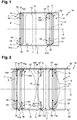
- the visual interaction portion 12, 12 'of the opening 2, two of which are shown respectively on the figures 1 to 3 and 5 is the portion of the opening 2 through which a user can look, for example to observe the landscape.
- the visual interaction portion does not necessarily represent the entire opening portion facing the passenger, but this visual interaction portion defines an opening portion through which the passenger can see at least by. part, for example outward.
- an opening 2 extends over two passenger seats, the latter comprises two visual interaction portions 12, 12 'associated with the two respective users.
- each user can therefore choose to hide or release the associated visual interaction portion 12, 12 ', without acting on the obscuring or release of the visual interaction portion 12, 12' associated with the neighboring user, by acting on the light intensity variation means 11a - 11c which will be described in detail below.
- the window opening 1a comprises a shutter 7, 7 'for each visual interaction portion 12, 12' associated with the user considered.
- the window opening 1a further comprises two rails respectively upper 13 and lower 14 mounted opposite one another on the respective upper 3 and lower 4 edges of the bay 1a.
- the length of the rails 13, 14 and the width of the opening 2 are identical, so that the opposite ends of the rails do not protrude from the window opening 1a.
- the rails have a length greater than the width of the opening 2 and therefore extend beyond the side edges 5, 6 of the window opening 1b.
- each shutter 7, 7 ' is connected to the upper 3 and lower 4 edges of the bay 1a by means of a guide pin 15, 15' on which said shutter 7, 7 'is mounted: the opposite ends 17, 18 ; 17 ', 18' of the guide axis 15, 15 'of the shutter in question 7, 7' cooperate with the two respective rails 13, 14. More precisely, this guide axis 15 extends parallel to the transverse axis Y of the opening 2 and comprises two ends of shafts 150, 151; 150 ', 151' integral with the upper 70, 70 'and lower 71, 71' opposite ends of the shutter 7, 7 ', and passing through the longitudinal axis Z, Z' of the shutter 7, 7 '.
- the end 17, 17 'of the upper shaft end 150, 150' cooperates in translation with the upper rail 13, while the end 18, 18 'of the lower shaft end 151, 151' cooperates in translation with the lower rail 14.
- the guide axis 15, 15 'and the rails 13, 14 form the means for varying the light intensity 11a in the first embodiment of the invention.
- the ends of the shaft ends 17, 17 ', 18, 18' are flattened so that they can each slide in a longitudinal groove 140, 210, 220 of the rail in question 14, 21, 22 (see figures 4 , 6a and 6b ).
- the ends of the shaft ends 17, 17 ', 18, 18' comprise runners or rollers 28 (see figure 3 ) to cooperate in translation with the considered rails 21, 22.
- each rail 13, 14 can also include a stop (not shown in figure 1 ) located in the vicinity of the middle of said rail 13, 14, and which blocks the movement of the shutter 7, 7 'beyond this stop. The movement of each shutter 7, 7 'is therefore confined between the considered side edge 5, 6 of the window opening 1 and the stops.
- the window opening 1b comprises first 7, 7 'and second 8, 8' shutters for each visual interaction portion 12, 12 'associated with the user considered.
- the flaps 7 'and 8' are in their position for closing off the portion visual interaction 12 ', while the flaps 7 and 8 are in an intermediate position between the disengaged position and the closed position of the visual interaction portion 12.
- the window opening 1b comprises two pairs of rails respectively upper 19 and lower 20 mounted opposite one another on the respective upper edges 3 and lower 4 of the opening 1b. Furthermore, each pair of rails 19, 20 comprises first 21 and second 22 rails, arranged so that the first rails 21 of the respective pairs of rails 19, 20 are opposite, and that the second rails 22 of the pairs of rails respective 19, 20 are also opposite. Finally, the rails 21, 22 of each pair of rails 19, 20 are parallel.
- each flap 7, 7 ', 8, 8' is connected to the upper 3 and lower 4 edges of the bay 1b via an axis of guide 15, 15 ', 16, 16' on which said shutter 7, 7 ', 8, 8' is mounted, the guide axis 15, 15 ', 16, 16' of each shutter 7, 7 ', 8, 8 'being formed by two ends of shafts 150, 150', 151, 151 ', 160, 160', 161, 161 'as described above.
- the opposite ends 150, 150 '; 151, 151 'of the guide axis 15, 15' of the first shutter 7, 7 ' cooperate in translation with the first rails 21 opposite the pairs of upper 19 and lower 20 rails
- the opposite ends 160, 160 ', 161, 161' of the guide axis 16, 16 'of the second flap 8, 8' cooperate in translation with the second rails 22 facing the pairs of upper 19 and lower 20 rails.
- the two guide pins 15, 15 ', 23, 23' and the two pairs of rails 19, 20 form the means for varying the light intensity 11b in the second embodiment of the invention.
- the user can thus translate the two flaps 7, 7 ', 8, 8' between their disengaged positions and partial concealment of the associated visual interaction portion 12, 12 ', which flap 7, 7', 8 , 8 'extends over the entire height of the opening 2, regardless of the position of said flap 7, 7', 8, 8 '.
- the user can vary the area occupied by the two flaps 7, 7 ', 8, 8' arranged in the position of. partial occultation of the associated visual interaction portion 12, 12 '.
- This occultation surface can be reduced when the two flaps 7, 8; 7 ', 8' are partly superimposed (left part of figures 2 and 3 ) or increased when the two shutters are not superimposed (right part of the figures 2 and 3 ).
- each rail 21, 22 can also include a stop 29 located in the vicinity of the middle of said rail 21, 22, and which blocks the movement of the shutter in question 7, 7 ', 8, 8' beyond this stop 29. The movement of each shutter 7, 7 ', 8, 8' is therefore confined between the lateral edge considered 5, 6 of the window opening 1b and the stops 29.
- each flap mounted on the bay 1a, 1b according to the first or the second embodiment is of the accordion type. It is thus configurable between a folded position and a deployed position. In addition, the direction of deployment and folding is perpendicular to the longitudinal axis X of the opening 2.
- the accordion flap thus has a variable width and adjustable by the user. Such an accordion flap allows the user to modify the surface of the portion obscured by said flap without it being necessary to translate or rotate the latter.
- the window opening 1c comprises at least one shutter 9, 9 ', preferably two shutters 9, 10; 9 ', 10' for each visual interaction portion 12, 12 'associated with the user considered.
- the window opening 1c comprises two rails respectively upper 13 and lower 14 mounted opposite one another on the respective upper 3 and lower 4 edges of the bay.
- the length of the rails 13, 14 and the width of the opening 2 are identical, so that the opposite ends of the rails do not protrude from the window opening 1c.
- the rails 13, 14 are larger than the width of the opening 2 and therefore protrude on either side of the side edges 5, 6 of the window opening 1c.
- Each shutter 9, 10; 9 ', 10' is connected to the upper 3 and lower 4 edges of the bay via its guide axis 23, 24; 23 ', 24' on which said shutter 9, 10; 9 ', 10' is mounted: the opposite ends 25, 26; 25 ', 26' of the guide pin 23, 24; 23 ', 24' of the shutter considered 9, 10; 9 ', 10' cooperate with the two respective rails 13, 14.
- the guide axis 23, 23 ', 24, 24' of the shutter 9, 9 ', 10, 10' is formed of a cylindrical rod, which shutter 9, 9 ', 10, 10 'is mounted to pivot around this cylindrical rod 23, 23', 24, 24 '.
- the shutter 9, 9 ', 10, 10' comprises at one of its edges a sheath 30, 30 ', 31, 31' in which the rod 23, 23 ', 24, 24' is fitted, but any other type of known pivoting connection means between the rod and the shutter is possible, in particular hinges.
- the two opposite ends 25, 26; 25 ', 26' of the rod 23, 24; 23 ', 24' protrude from the shutter 9, 10; 9 ', 10' to cooperate in translation with the considered rails 13, 14, as shown in the figures 6a and 6b .
- the structure of the opposite ends of the rod is as described above, in connection with the first and second embodiments of the bay 1a, 1b.
- the guide rod 23, 24, 23 ', 24' and the rails 13, 14 form the means for varying the light intensity 11c in the third embodiment of the invention.
- the flaps 9, 10, 9 ', 10' are movable in translation as described above, and also to pivot between a disengaged position in which each flap 9, 10, 9 ', 10' s 'extends in a plane perpendicular to opening 2 (see figure 6a ), and an at least partially closed position of the associated visual interaction portion 12, 12 'in which the shutters 9, 10, 9', 10 'extend in a plane parallel to the opening (see figure 6b ).
- the flaps 9, 10, 9 ', 10' being able to pivot through an amplitude of 180 °, the latter can extend parallel to the opening 2 on either side of the guide rod 23, 23 ' , 24, 24 '.
- the flaps 9, 10, 9 ', 10' mounted to pivot extend over the entire height of the opening 2, whatever their position.
- each rail 13, 14 can also include a stop located in the vicinity of the middle of said rail, and which blocks the movement of the shutter 9, 10, 9 ', 10' beyond this stop. The movement of each shutter 9, 10, 9 ', 10' is therefore confined between the relevant side edge of the window opening and the stops.
- the opposite ends of the guide rod are housed in holes made in the upper and lower edges of the bay.
- the shutter is obviously not movable in translation, but only in pivoting.
- each shutter comprises at least two panels superimposed and mounted on the same guide rod.
- the user can choose to rotate only one or the other of the panels. This allows the user to cover only a portion depending on the height of the opening of the visual interaction portion, and in fact modulate the amount of light obscured by the shutter.
- the shutters 7, 7 ', 8, 8', 9, 9 ', 10, 10' can be made of an opaque material, or else of a semi-transparent material allowing the shutter in position to occultation to let some of the light pass.
- part of the shutters 7, 7 ' can be opaque while another part of the shutters 8, 8' can be semi-transparent.
- Flaps 7, 7 '; 8, 8 ' can also have different widths, provided that the width of the largest of the shutters 7, 7' is less than or equal to the width of the opening 2 when the window opening 1a comprises only one shutter 7, 7 'per associated visual interaction portion 12, 12', and that the width of the largest of the shutters 7, 7 'is less than or equal to the half-width of the opening 2 when the window opening 1b, 1c comprises two shutters 7, 7 ', 8, 8', 9, 9 ', 10, 10' per portion of associated visual interaction 12, 12 '.
- the embodiments described above are in no way limiting, and modifications can be made to them without departing from the scope of the invention.
- the window bay can also include a single upper rail mounted on the upper edge of said bay.
- the lower edge of the bay comprises mechanical and / or magnetic holding means adapted to cooperate with the end considered of the guide axis of the shutter, making it possible to immobilize said shutter in its disengaged or hidden position.
Landscapes
- Engineering & Computer Science (AREA)
- Structural Engineering (AREA)
- Architecture (AREA)
- Civil Engineering (AREA)
- Mechanical Engineering (AREA)
- Curtains And Furnishings For Windows Or Doors (AREA)
- Wing Frames And Configurations (AREA)
- Vehicle Body Suspensions (AREA)
- Laser Beam Processing (AREA)
Applications Claiming Priority (1)
| Application Number | Priority Date | Filing Date | Title |
|---|---|---|---|
| FR1909960A FR3100558B1 (fr) | 2019-09-10 | 2019-09-10 | Baie de fenêtre d’un matériel ferroviaire roulant |
Publications (2)
| Publication Number | Publication Date |
|---|---|
| EP3792132A1 true EP3792132A1 (de) | 2021-03-17 |
| EP3792132B1 EP3792132B1 (de) | 2022-08-10 |
Family
ID=69375430
Family Applications (1)
| Application Number | Title | Priority Date | Filing Date |
|---|---|---|---|
| EP20195588.7A Active EP3792132B1 (de) | 2019-09-10 | 2020-09-10 | Fensteröffnug einer rollendem eisenbahnausrüstung |
Country Status (3)
| Country | Link |
|---|---|
| EP (1) | EP3792132B1 (de) |
| ES (1) | ES2928193T3 (de) |
| FR (1) | FR3100558B1 (de) |
Citations (5)
| Publication number | Priority date | Publication date | Assignee | Title |
|---|---|---|---|---|
| FR1075336A (fr) * | 1953-02-06 | 1954-10-14 | Bloc fenêtre et volets perfectionnés | |
| FR2493391A1 (fr) * | 1980-11-05 | 1982-05-07 | Sorapi Sarl | Fenetre et baies solaires |
| FR2970728A1 (fr) * | 2011-01-24 | 2012-07-27 | Accoplas Soc Gen De Fermetures | Volet coulissant |
| CN206031017U (zh) * | 2016-08-31 | 2017-03-22 | 中车唐山机车车辆有限公司 | 车用窗帘及机车 |
| FR3067293A1 (fr) * | 2017-06-08 | 2018-12-14 | Sncf Mobilites | Vehicule de transport comprenant un dispositif d'occultation d'une fenetre et un organe de montage allonge |
-
2019
- 2019-09-10 FR FR1909960A patent/FR3100558B1/fr active Active
-
2020
- 2020-09-10 ES ES20195588T patent/ES2928193T3/es active Active
- 2020-09-10 EP EP20195588.7A patent/EP3792132B1/de active Active
Patent Citations (5)
| Publication number | Priority date | Publication date | Assignee | Title |
|---|---|---|---|---|
| FR1075336A (fr) * | 1953-02-06 | 1954-10-14 | Bloc fenêtre et volets perfectionnés | |
| FR2493391A1 (fr) * | 1980-11-05 | 1982-05-07 | Sorapi Sarl | Fenetre et baies solaires |
| FR2970728A1 (fr) * | 2011-01-24 | 2012-07-27 | Accoplas Soc Gen De Fermetures | Volet coulissant |
| CN206031017U (zh) * | 2016-08-31 | 2017-03-22 | 中车唐山机车车辆有限公司 | 车用窗帘及机车 |
| FR3067293A1 (fr) * | 2017-06-08 | 2018-12-14 | Sncf Mobilites | Vehicule de transport comprenant un dispositif d'occultation d'une fenetre et un organe de montage allonge |
Also Published As
| Publication number | Publication date |
|---|---|
| FR3100558B1 (fr) | 2022-11-25 |
| FR3100558A1 (fr) | 2021-03-12 |
| EP3792132B1 (de) | 2022-08-10 |
| ES2928193T3 (es) | 2022-11-16 |
Similar Documents
| Publication | Publication Date | Title |
|---|---|---|
| EP2000340B1 (de) | Abdeckungsvorrichtung für Kraftfahrzeug mit über Kabel verbundenen Schwingarmen und entsprechendes Kraftfahrzeug | |
| FR2598124A1 (fr) | Systeme de lunette arriere escamotable pour vehicules | |
| EP0989008A2 (de) | Kraftfahrzeug mit einem in einer querliegenden Hintertür versenkbaren Dach | |
| EP1990501A2 (de) | Lamellenanordnung in einem Rollladen für einen Geäudeabschluss | |
| EP3792132B1 (de) | Fensteröffnug einer rollendem eisenbahnausrüstung | |
| FR3021254A1 (fr) | Dispositif vitre affleurant pour porte de vehicule a panneau mobile reglable, porte et vehicule automobile correspondants. | |
| EP1527925B1 (de) | Verdunkelungsvorrichtung für Kraftfahrzeugsglasoberfläche mit zwei Vorhänge und damit ausgerüstetes Fahrzeug | |
| FR2941736A1 (fr) | Dispositif d'occultation a reglages multiples | |
| EP3650303B1 (de) | Waggon eines schienenfahrzeugs mit verdunkelungsvorrichtung des verglasten öffnungselements | |
| EP2017105B1 (de) | Abdeckungsrollo für Kraftfahrzeug mit Schwenkzugstange und entsprechendes Fahrzeug | |
| FR2882090A1 (fr) | Dispositif d'occultation a rideau enrouleur manuel et multi position | |
| EP2080868B1 (de) | Schiebetür- oder Fensterflügel, insbesondere vom Typ Rollladen | |
| EP1747926A2 (de) | Beschattungsvorrichtung mit lateralen Ausgleichsklappen für ein KFZ-Dach und dazugehöriges KFZ | |
| EP4225597B1 (de) | Handbedienbares sonnendach für ein fahrzeug | |
| EP1683667B1 (de) | Abschattungsvorrichtung für ein Fahrzeug mit einer Rollobahn und entsprechendes Fahrzeug | |
| EP1669228A1 (de) | Abdeckungsvorrichtung bestehend aus zwei Rollos für ein Fahrzeug, und entsprechendes Fahrzeug | |
| EP1336519B1 (de) | Fensterrolle für Kraftfahrzeug mit Zugstange mit mobiler Abdeckung | |
| FR2853591A1 (fr) | Palette pare-soleil mobile le long du pavillon d'un vehicule, dispositif d'occultation d'un pavillon couple a une telle palette pare-soleil et vehicule correspondant | |
| EP2080652B1 (de) | Abdeckvorrichtung mit Zugstange, die mit Ausgleichselementen ausgestattet ist, und entsprechendes Kraftfahrzeug | |
| EP1614568A1 (de) | Verdunkelungsvorrichtung für Fahrzeug und entsprechendes Kraftfahrzeug | |
| EP1800924B1 (de) | KFZ mit Sonnenblende, die in einem in Längsrichtung verlaufenden mittigen Dachholm verstaut wird | |
| FR2926495A1 (fr) | Dispositif d'occultation d'une fenetre panoramique de vehicule automobile, a mecanisme de tension de rideaux | |
| WO2005056965A1 (fr) | Porte à ouverture latérale | |
| EP1852288A1 (de) | KFZ-Beschattungsvorrichtung mit klappbaren Spriegeln und dazugehöriges Fahrzeug | |
| EP2236729A2 (de) | Rollo-Kombination mit zwei Blenden insbesondere für Bullauge eines Luftfahrzeugs |
Legal Events
| Date | Code | Title | Description |
|---|---|---|---|
| PUAI | Public reference made under article 153(3) epc to a published international application that has entered the european phase |
Free format text: ORIGINAL CODE: 0009012 |
|
| STAA | Information on the status of an ep patent application or granted ep patent |
Free format text: STATUS: THE APPLICATION HAS BEEN PUBLISHED |
|
| AK | Designated contracting states |
Kind code of ref document: A1 Designated state(s): AL AT BE BG CH CY CZ DE DK EE ES FI FR GB GR HR HU IE IS IT LI LT LU LV MC MK MT NL NO PL PT RO RS SE SI SK SM TR |
|
| AX | Request for extension of the european patent |
Extension state: BA ME |
|
| STAA | Information on the status of an ep patent application or granted ep patent |
Free format text: STATUS: REQUEST FOR EXAMINATION WAS MADE |
|
| 17P | Request for examination filed |
Effective date: 20210916 |
|
| RBV | Designated contracting states (corrected) |
Designated state(s): AL AT BE BG CH CY CZ DE DK EE ES FI FR GB GR HR HU IE IS IT LI LT LU LV MC MK MT NL NO PL PT RO RS SE SI SK SM TR |
|
| GRAP | Despatch of communication of intention to grant a patent |
Free format text: ORIGINAL CODE: EPIDOSNIGR1 |
|
| STAA | Information on the status of an ep patent application or granted ep patent |
Free format text: STATUS: GRANT OF PATENT IS INTENDED |
|
| RIC1 | Information provided on ipc code assigned before grant |
Ipc: E06B 9/386 20060101ALI20220331BHEP Ipc: E06B 9/36 20060101ALI20220331BHEP Ipc: E06B 9/24 20060101ALI20220331BHEP Ipc: B61D 25/00 20060101AFI20220331BHEP |
|
| INTG | Intention to grant announced |
Effective date: 20220420 |
|
| GRAS | Grant fee paid |
Free format text: ORIGINAL CODE: EPIDOSNIGR3 |
|
| GRAA | (expected) grant |
Free format text: ORIGINAL CODE: 0009210 |
|
| STAA | Information on the status of an ep patent application or granted ep patent |
Free format text: STATUS: THE PATENT HAS BEEN GRANTED |
|
| AK | Designated contracting states |
Kind code of ref document: B1 Designated state(s): AL AT BE BG CH CY CZ DE DK EE ES FI FR GB GR HR HU IE IS IT LI LT LU LV MC MK MT NL NO PL PT RO RS SE SI SK SM TR |
|
| RAP3 | Party data changed (applicant data changed or rights of an application transferred) |
Owner name: SNCF VOYAGEURS |
|
| REG | Reference to a national code |
Ref country code: AT Ref legal event code: REF Ref document number: 1510335 Country of ref document: AT Kind code of ref document: T Effective date: 20220815 Ref country code: CH Ref legal event code: EP |
|
| REG | Reference to a national code |
Ref country code: DE Ref legal event code: R096 Ref document number: 602020004442 Country of ref document: DE |
|
| REG | Reference to a national code |
Ref country code: IE Ref legal event code: FG4D Free format text: LANGUAGE OF EP DOCUMENT: FRENCH |
|
| REG | Reference to a national code |
Ref country code: NL Ref legal event code: FP Ref country code: ES Ref legal event code: FG2A Ref document number: 2928193 Country of ref document: ES Kind code of ref document: T3 Effective date: 20221116 |
|
| REG | Reference to a national code |
Ref country code: LT Ref legal event code: MG9D |
|
| PG25 | Lapsed in a contracting state [announced via postgrant information from national office to epo] |
Ref country code: SE Free format text: LAPSE BECAUSE OF FAILURE TO SUBMIT A TRANSLATION OF THE DESCRIPTION OR TO PAY THE FEE WITHIN THE PRESCRIBED TIME-LIMIT Effective date: 20220810 Ref country code: RS Free format text: LAPSE BECAUSE OF FAILURE TO SUBMIT A TRANSLATION OF THE DESCRIPTION OR TO PAY THE FEE WITHIN THE PRESCRIBED TIME-LIMIT Effective date: 20220810 Ref country code: PT Free format text: LAPSE BECAUSE OF FAILURE TO SUBMIT A TRANSLATION OF THE DESCRIPTION OR TO PAY THE FEE WITHIN THE PRESCRIBED TIME-LIMIT Effective date: 20221212 Ref country code: NO Free format text: LAPSE BECAUSE OF FAILURE TO SUBMIT A TRANSLATION OF THE DESCRIPTION OR TO PAY THE FEE WITHIN THE PRESCRIBED TIME-LIMIT Effective date: 20221110 Ref country code: LV Free format text: LAPSE BECAUSE OF FAILURE TO SUBMIT A TRANSLATION OF THE DESCRIPTION OR TO PAY THE FEE WITHIN THE PRESCRIBED TIME-LIMIT Effective date: 20220810 Ref country code: LT Free format text: LAPSE BECAUSE OF FAILURE TO SUBMIT A TRANSLATION OF THE DESCRIPTION OR TO PAY THE FEE WITHIN THE PRESCRIBED TIME-LIMIT Effective date: 20220810 Ref country code: FI Free format text: LAPSE BECAUSE OF FAILURE TO SUBMIT A TRANSLATION OF THE DESCRIPTION OR TO PAY THE FEE WITHIN THE PRESCRIBED TIME-LIMIT Effective date: 20220810 |
|
| REG | Reference to a national code |
Ref country code: AT Ref legal event code: MK05 Ref document number: 1510335 Country of ref document: AT Kind code of ref document: T Effective date: 20220810 |
|
| PG25 | Lapsed in a contracting state [announced via postgrant information from national office to epo] |
Ref country code: PL Free format text: LAPSE BECAUSE OF FAILURE TO SUBMIT A TRANSLATION OF THE DESCRIPTION OR TO PAY THE FEE WITHIN THE PRESCRIBED TIME-LIMIT Effective date: 20220810 Ref country code: IS Free format text: LAPSE BECAUSE OF FAILURE TO SUBMIT A TRANSLATION OF THE DESCRIPTION OR TO PAY THE FEE WITHIN THE PRESCRIBED TIME-LIMIT Effective date: 20221210 Ref country code: HR Free format text: LAPSE BECAUSE OF FAILURE TO SUBMIT A TRANSLATION OF THE DESCRIPTION OR TO PAY THE FEE WITHIN THE PRESCRIBED TIME-LIMIT Effective date: 20220810 Ref country code: GR Free format text: LAPSE BECAUSE OF FAILURE TO SUBMIT A TRANSLATION OF THE DESCRIPTION OR TO PAY THE FEE WITHIN THE PRESCRIBED TIME-LIMIT Effective date: 20221111 |
|
| PG25 | Lapsed in a contracting state [announced via postgrant information from national office to epo] |
Ref country code: SM Free format text: LAPSE BECAUSE OF FAILURE TO SUBMIT A TRANSLATION OF THE DESCRIPTION OR TO PAY THE FEE WITHIN THE PRESCRIBED TIME-LIMIT Effective date: 20220810 Ref country code: RO Free format text: LAPSE BECAUSE OF FAILURE TO SUBMIT A TRANSLATION OF THE DESCRIPTION OR TO PAY THE FEE WITHIN THE PRESCRIBED TIME-LIMIT Effective date: 20220810 Ref country code: DK Free format text: LAPSE BECAUSE OF FAILURE TO SUBMIT A TRANSLATION OF THE DESCRIPTION OR TO PAY THE FEE WITHIN THE PRESCRIBED TIME-LIMIT Effective date: 20220810 Ref country code: CZ Free format text: LAPSE BECAUSE OF FAILURE TO SUBMIT A TRANSLATION OF THE DESCRIPTION OR TO PAY THE FEE WITHIN THE PRESCRIBED TIME-LIMIT Effective date: 20220810 Ref country code: AT Free format text: LAPSE BECAUSE OF FAILURE TO SUBMIT A TRANSLATION OF THE DESCRIPTION OR TO PAY THE FEE WITHIN THE PRESCRIBED TIME-LIMIT Effective date: 20220810 |
|
| REG | Reference to a national code |
Ref country code: DE Ref legal event code: R097 Ref document number: 602020004442 Country of ref document: DE |
|
| REG | Reference to a national code |
Ref country code: BE Ref legal event code: MM Effective date: 20220930 |
|
| PG25 | Lapsed in a contracting state [announced via postgrant information from national office to epo] |
Ref country code: SK Free format text: LAPSE BECAUSE OF FAILURE TO SUBMIT A TRANSLATION OF THE DESCRIPTION OR TO PAY THE FEE WITHIN THE PRESCRIBED TIME-LIMIT Effective date: 20220810 Ref country code: MC Free format text: LAPSE BECAUSE OF FAILURE TO SUBMIT A TRANSLATION OF THE DESCRIPTION OR TO PAY THE FEE WITHIN THE PRESCRIBED TIME-LIMIT Effective date: 20220810 Ref country code: EE Free format text: LAPSE BECAUSE OF FAILURE TO SUBMIT A TRANSLATION OF THE DESCRIPTION OR TO PAY THE FEE WITHIN THE PRESCRIBED TIME-LIMIT Effective date: 20220810 |
|
| PLBE | No opposition filed within time limit |
Free format text: ORIGINAL CODE: 0009261 |
|
| STAA | Information on the status of an ep patent application or granted ep patent |
Free format text: STATUS: NO OPPOSITION FILED WITHIN TIME LIMIT |
|
| PG25 | Lapsed in a contracting state [announced via postgrant information from national office to epo] |
Ref country code: LU Free format text: LAPSE BECAUSE OF NON-PAYMENT OF DUE FEES Effective date: 20220910 Ref country code: AL Free format text: LAPSE BECAUSE OF FAILURE TO SUBMIT A TRANSLATION OF THE DESCRIPTION OR TO PAY THE FEE WITHIN THE PRESCRIBED TIME-LIMIT Effective date: 20220810 |
|
| P01 | Opt-out of the competence of the unified patent court (upc) registered |
Effective date: 20230526 |
|
| 26N | No opposition filed |
Effective date: 20230511 |
|
| PG25 | Lapsed in a contracting state [announced via postgrant information from national office to epo] |
Ref country code: IE Free format text: LAPSE BECAUSE OF NON-PAYMENT OF DUE FEES Effective date: 20220910 |
|
| P02 | Opt-out of the competence of the unified patent court (upc) changed |
Effective date: 20230627 |
|
| PG25 | Lapsed in a contracting state [announced via postgrant information from national office to epo] |
Ref country code: SI Free format text: LAPSE BECAUSE OF FAILURE TO SUBMIT A TRANSLATION OF THE DESCRIPTION OR TO PAY THE FEE WITHIN THE PRESCRIBED TIME-LIMIT Effective date: 20220810 |
|
| PG25 | Lapsed in a contracting state [announced via postgrant information from national office to epo] |
Ref country code: BE Free format text: LAPSE BECAUSE OF NON-PAYMENT OF DUE FEES Effective date: 20220930 |
|
| PG25 | Lapsed in a contracting state [announced via postgrant information from national office to epo] |
Ref country code: CY Free format text: LAPSE BECAUSE OF FAILURE TO SUBMIT A TRANSLATION OF THE DESCRIPTION OR TO PAY THE FEE WITHIN THE PRESCRIBED TIME-LIMIT Effective date: 20220810 |
|
| REG | Reference to a national code |
Ref country code: CH Ref legal event code: PL |
|
| PG25 | Lapsed in a contracting state [announced via postgrant information from national office to epo] |
Ref country code: MK Free format text: LAPSE BECAUSE OF FAILURE TO SUBMIT A TRANSLATION OF THE DESCRIPTION OR TO PAY THE FEE WITHIN THE PRESCRIBED TIME-LIMIT Effective date: 20220810 Ref country code: HU Free format text: LAPSE BECAUSE OF FAILURE TO SUBMIT A TRANSLATION OF THE DESCRIPTION OR TO PAY THE FEE WITHIN THE PRESCRIBED TIME-LIMIT; INVALID AB INITIO Effective date: 20200910 |
|
| PG25 | Lapsed in a contracting state [announced via postgrant information from national office to epo] |
Ref country code: CH Free format text: LAPSE BECAUSE OF NON-PAYMENT OF DUE FEES Effective date: 20230930 |
|
| PG25 | Lapsed in a contracting state [announced via postgrant information from national office to epo] |
Ref country code: CH Free format text: LAPSE BECAUSE OF NON-PAYMENT OF DUE FEES Effective date: 20230930 Ref country code: BG Free format text: LAPSE BECAUSE OF FAILURE TO SUBMIT A TRANSLATION OF THE DESCRIPTION OR TO PAY THE FEE WITHIN THE PRESCRIBED TIME-LIMIT Effective date: 20220810 |
|
| PG25 | Lapsed in a contracting state [announced via postgrant information from national office to epo] |
Ref country code: MT Free format text: LAPSE BECAUSE OF FAILURE TO SUBMIT A TRANSLATION OF THE DESCRIPTION OR TO PAY THE FEE WITHIN THE PRESCRIBED TIME-LIMIT Effective date: 20220810 |
|
| GBPC | Gb: european patent ceased through non-payment of renewal fee |
Effective date: 20240910 |
|
| PG25 | Lapsed in a contracting state [announced via postgrant information from national office to epo] |
Ref country code: GB Free format text: LAPSE BECAUSE OF NON-PAYMENT OF DUE FEES Effective date: 20240910 |
|
| PGFP | Annual fee paid to national office [announced via postgrant information from national office to epo] |
Ref country code: DE Payment date: 20250916 Year of fee payment: 6 |
|
| PGFP | Annual fee paid to national office [announced via postgrant information from national office to epo] |
Ref country code: NL Payment date: 20250909 Year of fee payment: 6 Ref country code: IT Payment date: 20250909 Year of fee payment: 6 |
|
| PGFP | Annual fee paid to national office [announced via postgrant information from national office to epo] |
Ref country code: FR Payment date: 20250929 Year of fee payment: 6 |
|
| PG25 | Lapsed in a contracting state [announced via postgrant information from national office to epo] |
Ref country code: TR Free format text: LAPSE BECAUSE OF FAILURE TO SUBMIT A TRANSLATION OF THE DESCRIPTION OR TO PAY THE FEE WITHIN THE PRESCRIBED TIME-LIMIT Effective date: 20220810 |
|
| PGFP | Annual fee paid to national office [announced via postgrant information from national office to epo] |
Ref country code: ES Payment date: 20251015 Year of fee payment: 6 |