EP3792177B1 - Système comprenant un moteur électrique à courant continu sans balais pour un moteur à hélice - Google Patents
Système comprenant un moteur électrique à courant continu sans balais pour un moteur à hélice Download PDFInfo
- Publication number
- EP3792177B1 EP3792177B1 EP19306088.6A EP19306088A EP3792177B1 EP 3792177 B1 EP3792177 B1 EP 3792177B1 EP 19306088 A EP19306088 A EP 19306088A EP 3792177 B1 EP3792177 B1 EP 3792177B1
- Authority
- EP
- European Patent Office
- Prior art keywords
- windings
- alternator
- stator
- engine
- permanent magnets
- Prior art date
- Legal status (The legal status is an assumption and is not a legal conclusion. Google has not performed a legal analysis and makes no representation as to the accuracy of the status listed.)
- Active
Links
Images


Classifications
-
- B—PERFORMING OPERATIONS; TRANSPORTING
- B64—AIRCRAFT; AVIATION; COSMONAUTICS
- B64D—EQUIPMENT FOR FITTING IN OR TO AIRCRAFT; FLIGHT SUITS; PARACHUTES; ARRANGEMENT OR MOUNTING OF POWER PLANTS OR PROPULSION TRANSMISSIONS IN AIRCRAFT
- B64D27/00—Arrangement or mounting of power plants in aircraft; Aircraft characterised by the type or position of power plants
- B64D27/02—Aircraft characterised by the type or position of power plants
- B64D27/24—Aircraft characterised by the type or position of power plants using steam or spring force
-
- B—PERFORMING OPERATIONS; TRANSPORTING
- B64—AIRCRAFT; AVIATION; COSMONAUTICS
- B64C—AEROPLANES; HELICOPTERS
- B64C11/00—Propellers, e.g. of ducted type; Features common to propellers and rotors for rotorcraft
- B64C11/30—Blade pitch-changing mechanisms
- B64C11/44—Blade pitch-changing mechanisms electric
-
- B—PERFORMING OPERATIONS; TRANSPORTING
- B64—AIRCRAFT; AVIATION; COSMONAUTICS
- B64C—AEROPLANES; HELICOPTERS
- B64C11/00—Propellers, e.g. of ducted type; Features common to propellers and rotors for rotorcraft
-
- B—PERFORMING OPERATIONS; TRANSPORTING
- B64—AIRCRAFT; AVIATION; COSMONAUTICS
- B64C—AEROPLANES; HELICOPTERS
- B64C19/00—Aircraft control not otherwise provided for
- B64C19/02—Conjoint controls
-
- B—PERFORMING OPERATIONS; TRANSPORTING
- B64—AIRCRAFT; AVIATION; COSMONAUTICS
- B64C—AEROPLANES; HELICOPTERS
- B64C27/00—Rotorcraft; Rotors peculiar thereto
- B64C27/22—Compound rotorcraft, i.e. aircraft using in flight the features of both aeroplane and rotorcraft
- B64C27/28—Compound rotorcraft, i.e. aircraft using in flight the features of both aeroplane and rotorcraft with forward-propulsion propellers pivotable to act as lifting rotors
-
- B—PERFORMING OPERATIONS; TRANSPORTING
- B64—AIRCRAFT; AVIATION; COSMONAUTICS
- B64D—EQUIPMENT FOR FITTING IN OR TO AIRCRAFT; FLIGHT SUITS; PARACHUTES; ARRANGEMENT OR MOUNTING OF POWER PLANTS OR PROPULSION TRANSMISSIONS IN AIRCRAFT
- B64D15/00—De-icing or preventing icing on exterior surfaces of aircraft
- B64D15/12—De-icing or preventing icing on exterior surfaces of aircraft by electric heating
-
- B—PERFORMING OPERATIONS; TRANSPORTING
- B64—AIRCRAFT; AVIATION; COSMONAUTICS
- B64D—EQUIPMENT FOR FITTING IN OR TO AIRCRAFT; FLIGHT SUITS; PARACHUTES; ARRANGEMENT OR MOUNTING OF POWER PLANTS OR PROPULSION TRANSMISSIONS IN AIRCRAFT
- B64D27/00—Arrangement or mounting of power plants in aircraft; Aircraft characterised by the type or position of power plants
- B64D27/02—Aircraft characterised by the type or position of power plants
- B64D27/30—Aircraft characterised by electric power plants
- B64D27/32—Aircraft characterised by electric power plants within, or attached to, fuselages
-
- B—PERFORMING OPERATIONS; TRANSPORTING
- B64—AIRCRAFT; AVIATION; COSMONAUTICS
- B64D—EQUIPMENT FOR FITTING IN OR TO AIRCRAFT; FLIGHT SUITS; PARACHUTES; ARRANGEMENT OR MOUNTING OF POWER PLANTS OR PROPULSION TRANSMISSIONS IN AIRCRAFT
- B64D27/00—Arrangement or mounting of power plants in aircraft; Aircraft characterised by the type or position of power plants
- B64D27/02—Aircraft characterised by the type or position of power plants
- B64D27/30—Aircraft characterised by electric power plants
- B64D27/34—All-electric aircraft
-
- B—PERFORMING OPERATIONS; TRANSPORTING
- B64—AIRCRAFT; AVIATION; COSMONAUTICS
- B64D—EQUIPMENT FOR FITTING IN OR TO AIRCRAFT; FLIGHT SUITS; PARACHUTES; ARRANGEMENT OR MOUNTING OF POWER PLANTS OR PROPULSION TRANSMISSIONS IN AIRCRAFT
- B64D31/00—Power plant control systems; Arrangement of power plant control systems in aircraft
- B64D31/16—Power plant control systems; Arrangement of power plant control systems in aircraft for electric power plants
-
- B—PERFORMING OPERATIONS; TRANSPORTING
- B64—AIRCRAFT; AVIATION; COSMONAUTICS
- B64D—EQUIPMENT FOR FITTING IN OR TO AIRCRAFT; FLIGHT SUITS; PARACHUTES; ARRANGEMENT OR MOUNTING OF POWER PLANTS OR PROPULSION TRANSMISSIONS IN AIRCRAFT
- B64D35/00—Transmitting power from power plants to propellers or rotors; Arrangements of transmissions
- B64D35/02—Transmitting power from power plants to propellers or rotors; Arrangements of transmissions specially adapted for specific power plants
- B64D35/021—Transmitting power from power plants to propellers or rotors; Arrangements of transmissions specially adapted for specific power plants for electric power plants
- B64D35/026—Transmitting power from power plants to propellers or rotors; Arrangements of transmissions specially adapted for specific power plants for electric power plants the electric power plant being integral with the propeller or rotor
-
- B—PERFORMING OPERATIONS; TRANSPORTING
- B64—AIRCRAFT; AVIATION; COSMONAUTICS
- B64U—UNMANNED AERIAL VEHICLES [UAV]; EQUIPMENT THEREFOR
- B64U50/00—Propulsion; Power supply
- B64U50/10—Propulsion
- B64U50/19—Propulsion using electrically powered motors
-
- H—ELECTRICITY
- H01—ELECTRIC ELEMENTS
- H01F—MAGNETS; INDUCTANCES; TRANSFORMERS; SELECTION OF MATERIALS FOR THEIR MAGNETIC PROPERTIES
- H01F38/00—Adaptations of transformers or inductances for specific applications or functions
- H01F38/18—Rotary transformers
-
- H—ELECTRICITY
- H02—GENERATION; CONVERSION OR DISTRIBUTION OF ELECTRIC POWER
- H02K—DYNAMO-ELECTRIC MACHINES
- H02K1/00—Details of the magnetic circuit
- H02K1/06—Details of the magnetic circuit characterised by the shape, form or construction
- H02K1/12—Stationary parts of the magnetic circuit
-
- H—ELECTRICITY
- H02—GENERATION; CONVERSION OR DISTRIBUTION OF ELECTRIC POWER
- H02K—DYNAMO-ELECTRIC MACHINES
- H02K1/00—Details of the magnetic circuit
- H02K1/06—Details of the magnetic circuit characterised by the shape, form or construction
- H02K1/12—Stationary parts of the magnetic circuit
- H02K1/14—Stator cores with salient poles
-
- H—ELECTRICITY
- H02—GENERATION; CONVERSION OR DISTRIBUTION OF ELECTRIC POWER
- H02K—DYNAMO-ELECTRIC MACHINES
- H02K1/00—Details of the magnetic circuit
- H02K1/06—Details of the magnetic circuit characterised by the shape, form or construction
- H02K1/12—Stationary parts of the magnetic circuit
- H02K1/17—Stator cores with permanent magnets
-
- H—ELECTRICITY
- H02—GENERATION; CONVERSION OR DISTRIBUTION OF ELECTRIC POWER
- H02K—DYNAMO-ELECTRIC MACHINES
- H02K1/00—Details of the magnetic circuit
- H02K1/06—Details of the magnetic circuit characterised by the shape, form or construction
- H02K1/22—Rotating parts of the magnetic circuit
- H02K1/27—Rotor cores with permanent magnets
- H02K1/2786—Outer rotors
-
- H—ELECTRICITY
- H02—GENERATION; CONVERSION OR DISTRIBUTION OF ELECTRIC POWER
- H02K—DYNAMO-ELECTRIC MACHINES
- H02K11/00—Structural association of dynamo-electric machines with electric components or with devices for shielding, monitoring or protection
- H02K11/0094—Structural association with other electrical or electronic devices
-
- H—ELECTRICITY
- H02—GENERATION; CONVERSION OR DISTRIBUTION OF ELECTRIC POWER
- H02K—DYNAMO-ELECTRIC MACHINES
- H02K11/00—Structural association of dynamo-electric machines with electric components or with devices for shielding, monitoring or protection
- H02K11/30—Structural association with control circuits or drive circuits
- H02K11/33—Drive circuits, e.g. power electronics
-
- H—ELECTRICITY
- H02—GENERATION; CONVERSION OR DISTRIBUTION OF ELECTRIC POWER
- H02K—DYNAMO-ELECTRIC MACHINES
- H02K16/00—Machines with more than one rotor or stator
- H02K16/04—Machines with one rotor and two stators
-
- H—ELECTRICITY
- H02—GENERATION; CONVERSION OR DISTRIBUTION OF ELECTRIC POWER
- H02K—DYNAMO-ELECTRIC MACHINES
- H02K21/00—Synchronous motors having permanent magnets; Synchronous generators having permanent magnets
- H02K21/12—Synchronous motors having permanent magnets; Synchronous generators having permanent magnets with stationary armatures and rotating magnets
-
- H—ELECTRICITY
- H02—GENERATION; CONVERSION OR DISTRIBUTION OF ELECTRIC POWER
- H02P—CONTROL OR REGULATION OF ELECTRIC MOTORS, ELECTRIC GENERATORS OR DYNAMO-ELECTRIC CONVERTERS; CONTROLLING TRANSFORMERS, REACTORS OR CHOKE COILS
- H02P6/00—Arrangements for controlling synchronous motors or other dynamo-electric motors using electronic commutation dependent on the rotor position; Electronic commutators therefor
- H02P6/14—Electronic commutators
-
- H—ELECTRICITY
- H02—GENERATION; CONVERSION OR DISTRIBUTION OF ELECTRIC POWER
- H02K—DYNAMO-ELECTRIC MACHINES
- H02K15/00—Processes or apparatus specially adapted for manufacturing, assembling, maintaining or repairing of dynamo-electric machines
- H02K15/02—Processes or apparatus specially adapted for manufacturing, assembling, maintaining or repairing of dynamo-electric machines of stator or rotor bodies
- H02K15/03—Processes or apparatus specially adapted for manufacturing, assembling, maintaining or repairing of dynamo-electric machines of stator or rotor bodies having permanent magnets
-
- Y—GENERAL TAGGING OF NEW TECHNOLOGICAL DEVELOPMENTS; GENERAL TAGGING OF CROSS-SECTIONAL TECHNOLOGIES SPANNING OVER SEVERAL SECTIONS OF THE IPC; TECHNICAL SUBJECTS COVERED BY FORMER USPC CROSS-REFERENCE ART COLLECTIONS [XRACs] AND DIGESTS
- Y02—TECHNOLOGIES OR APPLICATIONS FOR MITIGATION OR ADAPTATION AGAINST CLIMATE CHANGE
- Y02T—CLIMATE CHANGE MITIGATION TECHNOLOGIES RELATED TO TRANSPORTATION
- Y02T50/00—Aeronautics or air transport
- Y02T50/40—Weight reduction
Definitions
- the present disclosure relates generally to an electric motor for an aircraft propeller.
- Electric (e.g., DC) motors are configured to convert an electric current (electrical energy) into mechanical energy, by passing the current through one or more windings that each generate a magnetic field.
- One or more permanent magnets are used to produce one or more secondary magnetic fields, and a reciprocating force is generated in between the windings on one side and the magnets on the other due to the interaction between the magnetic fields.
- a mechanical arrangement of commutators may be used to energise the windings in the armature of a DC motor.
- an electrical mechanism so called brushless DC motors or BLDC.
- the permanent magnets form part of the stator of a motor (and the windings part of the rotor)
- the windings may form part of the stator and the permanent magnets may form part of the rotor.
- the stationary windings can be configured to move the permanent magnets (and the rotor) by being energised in a controlled sequence to produce a rotating magnetic field, see for example US2009085505 A1 .
- FIG. 1 One typical sequence is illustrated in Fig. 1 , and may be referred to as a trapezoidal control scheme, in which the stationary windings may be energised in a particular sequence to drive the motor.
- a three-phase brushless DC motor 2 (shown schematically and electrically) is driven in an anticlockwise direction by a motor controller 1 (which may be a MOSFET bridge), wherein for each step in the commutation sequence, one of the windings (either "U", "V” or "W") is driven high by the controller 1, while the other is driven low and the third is left floating.
- a motor controller 1 which may be a MOSFET bridge
- winding U is high (forming an N pole)
- winding V is low (forming a S pole)
- winding W is floating.
- the resulting magnetic field is configured to move the rotor anticlockwise since its permanent magnets will be repelled by one winding and attracted by the next.
- the subsequent stage shows winding U remaining high while winding the switches to floating, and winding W switches low. This can be seen as maintaining the rotation of the magnetic field and moving rotor.
- the remaining commutation steps follow a similar sequence.
- Medium-sized propeller aircraft are typically equipped with a single power plant on each wing, wherein the propellers used on such aircraft are typically variable pitch to allow operation at a substantially constant predetermined RPM and in addition to allow a generation of reverse thrust or feather the propeller to reduce windmilling drag and prevent any risk of overspeed.
- the variation of pitch may be achieved using an electro-hydro-mechanic system.
- the power required by such systems may be about 1-4% of the total power output of each power plant.
- Modern propellers may additionally include a blade deicing system, which can include a heater in the form of a resistive element that covers or extends along the bottom part of the trailing edge of the propeller blade.
- a blade deicing system which can include a heater in the form of a resistive element that covers or extends along the bottom part of the trailing edge of the propeller blade.
- Such heaters typically require a three-phase AC or single phase DC electrical power supply, and typically require about 1-4% of the total power output of each power plant.
- variable pitch mechanism and the deicing mechanism for the propeller blades require installation of various components on the rotating propeller, leading to the need to transfer electric or hydraulic power from the static side of the power plant or aircraft to the rotating propeller.
- Electrical power transfer can be achieved using brush contacts and slip ring mechanisms, which may have high weight or cost drawbacks and also involve wear over time.
- Hydraulic power transmission can be achieved using transfer bearings, which also involve high weight or cost drawbacks, as well as introducing potential leakage problems.
- a system comprising a brushless DC (“BLDC”) electric motor for a propeller engine (and/or for driving a plurality of propellers), and a motor controller.
- the motor comprises a rotor, which may be configured to rotate about an axis, wherein the rotor includes one or more permanent magnets and one or more alternator windings, and the motor further comprises a stator including one or more stator windings.
- the controller is configured to apply a first, transient DC voltage to the windings of the stator, wherein the first, transient DC voltage is configured to provide commutation switching for the windings of the stator so as to generate a torque on the rotor via the permanent magnets.
- the controller is further configured to apply a second, static DC voltage to the windings of the stator, wherein the second, static DC voltage is configured to induce an electric current in the alternator windings so as to generate an AC voltage in the alternator windings.
- a single motor and, also importantly, single controller
- a single motor can be used to provide rotational drive to the propellers of the propeller engine, and generate electric power on the rotating side of the engine to power variable pitch, deicing and other systems on the rotating side. Due to this the technology disclosed herein may be particularly suitable for a direct drive propeller engine, in which the electric motor directly drives the rotating portion of the engine (i.e., without use of a gear assembly) and aspects relate to a direct drive propeller engine comprising the system described above.
- propeller engine is intended to refer to the engine assembly as a whole, e.g., including propellers, propeller hub, driving means (in this case an electric motor) and various other components.
- driving means in this case an electric motor
- propeller engine assembly could be used interchangeably with this term.
- one important characteristic of the system is that it allows installation of the motor controller on the static portion (aircraft side), which can avoid high G-field constraints associated with installation on the rotating portion (i.e., with the propellers). This also allows an easy electrical connection to the aircraft electrical network and other aircraft systems like flight control computers, etc.
- the alternator windings and/or permanent magnets may be distributed around a circumference of the rotor and may rotate about a common axis (e.g., the rotational axis of the rotor referred to above).
- the stator may comprise a hub (or shaft) and magnetic elements may extend from the hub (e.g., in pairs having an opposing relationship).
- the stator windings may be wound around each magnetic element.
- Each magnetic element may extend from the hub in an opposing direction to another (e.g., opposing) magnetic element.
- the permanent magnets may comprise alternating north and south poles located around the circumference of the rotor.
- the alternator windings may be located circumferentially between two (or more) of the permanent magnets of the rotor. This can provide a compact assembly and optimise the electrical arrangement of the alternator windings and permanent magnets.
- the alternator windings may be located concentrically within the permanent magnets of the rotor, so that the permanent magnets form a cylindrical assembly located at a first radial position, while the alternator windings are located within (or outside) the cylindrical assembly of the permanent magnets at a second radial position.
- the permanent magnets and the alternator may be axially displaced.
- the system may further comprise one or more position sensors configured to produce signals indicative of the position of the permanent magnets and/or the alternator windings.
- the controller may be configured to receive the signals from the position sensors and process these signals to determine the relative positions of the stator windings and the permanent magnets and/or the alternator windings.
- the controller may be configured to use the relative positions determined from the signals to provide the commutation switching for the windings of the stator and generate a torque on the rotor as aforesaid.
- a propeller engine comprising a system as described in any of the aspects and embodiments described above, wherein the motor is configured to drive the propellers of the propeller engine.
- the propellers may be driven directly by the motor, for example without the use of a gear assembly and/or reduction transmission and/or transmission shaft.
- the stator can advantageously be installed directly in the propeller hub and the stator directly attached to the aircraft structure thus reducing the number of components (and weight and cost).
- the controller may be configured to control the rotational speed of the propeller (e.g., one or more propellers thereof) as well as the electrical power supplied by the alternator. Both the rotational speed and the electrical power may be varied by the controller, for example based on engine thrust requirements and electrical power requirements respectively.
- the controller may receive engine thrust requirements from an external device, such as a command signal from an engine management system (e.g., controlled by an operator or pilot).
- the controller may determine electrical power requirements from a feedback mechanism of an electrically powered system that is powered by the alternator (e.g., one or more of the electrically powered systems described below and elsewhere herein).
- the controller may be configured to regulate the first, static DC voltage supplied to the alternator coils.
- the controller may determine a demand for electrical power from the alternator, optionally using one or more sensors configured to produce signals representative of the AC or DC current and/or voltage produced by the alternator.
- the controller may regulate the first, static DC voltage supplied to the alternator coils based on the determined demand.
- the engine may further comprise a rotating portion comprising the rotor and a plurality of propellers, and a non-rotating portion comprising the stator, wherein the rotating portion of the engine may further comprise one or more electrically powered systems.
- the one or more electrically powered systems may comprise one or more of a system for varying a pitch of the propellers and/or system for deicing the propellers.
- the engine may further comprise a magnetic coupling between the static portion and the non-rotating portion, wherein the magnetic coupling is configured to communicate one or more signals between the static portion and the non-rotating portion.
- the controller may be configured to send and receive signals via the magnetic coupling to the one or more electrically powered systems that are located on the non-rotating portion.
- the one or more electrically powered systems may be configured to send and receive signals via the magnetic coupling to the controller.
- the controller and the one or more electrically powered systems may communicate via the magnetic coupling.
- the magnetic coupling may comprise the existing components of the assembly, such as the stator windings and alternator windings.
- the controller may be further configured to generate electrical power in the alternator windings by applying an AC voltage on the stator windings, but without commutation switching or other variability that would drive the rotor for rotation.
- This mode of operation can be useful in order to change the pitch on the propellers if the rotor is not rotating, such as when the aircraft is grounded.
- an aircraft comprising a propulsion system including one or more propeller engines, wherein at least one of which is (or all of them are) a propeller engine as described in any of the aspects and embodiments described above.
- an unmanned aerial vehicle comprising a propulsion system including one or more propeller engines, wherein at least one of which is (or all of them are) a propeller engine as described in any of the aspects and embodiments described above.
- an electric motor or machine for an aircraft which may be otherwise referred to herein as an aeroplane.
- the aircraft may be of the type that is propelled (e.g., in any direction, including forward, backwards, up, down, sideways) by thrust from one or more propeller engines (e.g., fixed or rotary wing), and the electric motor may be configured to drive one of the propeller engines.
- each propeller engine may be configured to be driven by one such electric motor.
- the aircraft may be of any suitable size, shape, and wing configuration.
- the aircraft may be for one or more of recreation, transportation of goods and/or people, military, and research.
- the aircraft may be one that is flown by a pilot on board the aircraft, or alternatively may be an unmanned aerial vehicle (“UAV") that can be remotely or computer-controlled, for example a drone.
- UAV unmanned aerial vehicle
- a vertical lift propulsion system may benefit from a propeller engine as disclosed herein, and aspects of the disclosure may relate to a vertical lift propulsion system comprising a propeller engine and electric motor as described herein.
- the technology disclosed herein may be particularly suitable for unmanned aerial vehicles and/or propeller driven aircraft.
- aircraft that are driven by one or more propeller assemblies, wherein electrically powered and/or electro-mechanical systems are located on the rotating portion of the propeller assemblies, can benefit from the technology disclosed herein, such as variable pitch and/or deicing systems or any other electrical system.
- the electric motor described herein is intended to combine a brushless direct current (“BLDC”) electric motor and an alternator in a common assembly for driving a propeller of an aircraft.
- BLDC brushless direct current
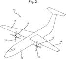
- Fig. 2 shows an aircraft 10 that comprises a fuselage 12 and a pair of fixed wings 14 extending from the fuselage 12. Located on each wing is a propeller engine 16, each of which is configured to drive a propeller assembly that comprises a multiple of propellers 18.
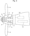
- Fig. 3 shows the propeller engine 16 in isolation and schematically, from which it can be seen the propellers 18 extend from a rotating propeller hub 20.
- the engine 16 comprises an electric motor 30 configured to rotate the propellers 18 to provide thrust for the aircraft 10.
- the motor 30 is installed in the propeller hub 20 to remove the need for this additional assembly.
- One or more bearings 31 or bearing systems may be provided to allow rotation of the propeller hub 20 (and other rotating portions of the engine) with respect to the static portions of the engine 16.
- the engine 16 may further comprise a motor controller 100 (e.g., processor or circuitry) configured to control operation of the electric motor 30.
- a motor controller 100 e.g., processor or circuitry
- the controller 100 is shown as being incorporated within the engine 16 in Fig. 3 , this may not be the case and the controller 100 could be incorporated remotely, for example as part of an engine management system of the aircraft 10.
- the engine management system may be located anywhere on the aircraft 10, for example in the cockpit, or even (e.g., in the case of an unmanned aerial vehicle) remotely from the aircraft.
- the broadest aspects of the present disclosure may relate to a system comprising the brushless DC (“BLDC”) electric motor 30 and the controller 100.
- BLDC brushless DC
- the engine 16 may further comprise one or more electric power sources 102, for example one or more batteries, fuel cells, or an Auxiliary Power Unit using a thermal engine, etc.
- one or more electric power sources 102 for example one or more batteries, fuel cells, or an Auxiliary Power Unit using a thermal engine, etc.
- the engine 16 may further comprise one or more electrically powered systems 24 located on a rotating portion of the propeller assembly, e.g., within the propeller hub 20.
- the one or more electrically powered systems 24 may comprise one or more of a system 26 for varying a pitch of the propellers 18 and/or system 28 for deicing the propellers and/or any other system 18.
- Fig. 4 schematically shows one embodiment of an electric motor 30 (or electric motor system) of the present disclosure, which may be used in the engine 16 shown in Figs. 2 and 3 and elsewhere.
- the electric motor 30 comprises a rotating portion 40 (or rotor) and a static portion 42 (or stator).
- the electric motor 30 comprises a plurality of permanent magnets 32, including a first permanent magnet 32A and a second permanent magnet 32B.
- the first permanent magnet 32A may be a 'north seeking' magnet
- the second permanent magnet 32B may be a 'south seeking' magnet.
- the permanent magnets 32 are configured to rotate (e.g., with the propeller hub 20) with the rotating portion 40 about a central axis A.
- the electric motor 30 further comprises an alternator 34 made up of a pair of alternator windings 34A, 34B that are wound around respective poles 35, which may be made from any suitable magnetic material such as iron (e.g., iron sheet metal or iron plates).
- alternator 34 is configured to rotate with the permanent magnets 32 as part of the rotating portion 40 of the electric motor 30.
- a pair of alternator windings 34A, 34B are shown, any number of windings may be used and the disclosure is not limited to the use of two windings.
- the alternator windings 34A, 34B and permanent magnets 32 may be distributed around the circumference of the rotating portion 40, and may be imbricated (e.g., rotate about a common axis such as the central axis A).
- the alternator 34 and/or alternator windings 34A, 34B may be configured to generate electricity, which may be used to power one or more electrically powered and/or electro-mechanical systems 24, such as variable pitch 26 and/or deicing systems 28 or any other electrical system located on the rotating portion 40.
- Positioning the permanent magnets 32 and alternator 34 as part of the rotating portion 40 removes the requirement to transfer electricity from the static portion 42 of the motor 30 via electrical connections such as brushes and slip rings, as well as hydraulic connections for powering components or one or more electrically powered and/or electro-mechanical systems associated with the rotating portion 40, such as variable pitch and/or deicing systems or any other electrical system.
- the static portion 42 of the electric motor 30 comprises a hub (or shaft) 44, extending from which may be opposed magnetic elements 46 (i.e., extending in opposite directions), wherein a plurality of windings 48A, 48B are wound around each magnetic element 46.
- the number of windings (two are shown in Fig. 4 , namely 48A, 48B) on the static portion 42 may be varied as necessary.
- the number of windings may relate to the number of phases of the electric motor, such as 6 windings for a 3 phase motor.
- the static portion 42 may be positioned in the centre of the motor, and may be attached to a structure (e.g., engine 16) that may be, in turn, attached to or integral with a fixed wing of an aircraft (e.g., wing 14).
- the permanent magnets 32 may comprise alternating north and south poles located around the circumference of the rotating portion 40 (relative to axis A).
- the rotating portion 40 may be installed in the engine 16 of Fig. 3 , and could be installed into the propeller hub 20 or the main body of the engine 16 itself, as shown in Fig. 3 . In any case, the permanent magnets 32 are rotating with the propellers 18 of the engine 16.
- the alternator 34 comprises the alternator windings 34A, 34B distributed about the circumference (relative to axis A), wherein the number of windings of the alternator 34 may be a multiple of the number of phases of the alternator, such as 3 phase alternator that would have 6 windings.
- the electric motor 30 may further comprise various position sensors 50 configured to produce signals indicative of the position of one or more of the components of the rotating portion 40, for example the permanent magnets 32 and/or the alternator 34.
- the controller 100 may receive the signals and may be configured to determine the relative positions of the components of the rotating portion 40 and the static portion 42. This can assist the controller 102 in sending appropriate electrical signals to the windings 48A, 48B of the motor 30.
- the position sensors 50 may be positioned on the static portion 42 so that the signal transmission to the controller 100 is simplified. Although they may be positioned on the rotating portion 40 this can make it more difficult to communicate with the controller 100.
- the permanent magnets 32 and the alternator 34 are imbricated and share the same rotational axis A.
- the permanent magnets 32 and the alternator 34 could be axially displaced, while still using a common static portion 42 as a driving element. Both of these embodiments could be referred to as a radial magnetic flux arrangement.
- the structural elements described herein could be used with an axial magnetic flux arrangement.
- the permanent magnets 32 and the alternator 34 could be imbricated or concentric, wherein the alternator windings 34A, 34B could be installed on an inner circumference inside an outer circumference of permanent magnets, which could maximise electric motor torque.
- the controller 100 may operate similar to a conventional control for a brushless DC motor (e.g., as described above with respect to Fig. 1 ) to provide commutation switching for the windings 48A, 48B of the static portion 42 so as to generate a torque on the rotating portion 40 and cause rotation of the rotating portion 40 about the axis A.
- a brushless DC motor e.g., as described above with respect to Fig. 1
- the controller 100 may apply a first, transient and/or variable DC voltage (e.g., from power source 102) to the windings 48A, 48B of the static portion 42, which transient or variable DC voltage is applied to the windings 48A, 48B sequentially in order to generate north or south seeking magnetic fields for driving the rotating portion 40.
- the controller 100 may apply the transient or variable DC voltage in a trapezoidal, sinusoidal or field-oriented control scheme, as discussed above.
- the controller may be configured to position the fields with an adequate offset in order to generate the appropriate magnetic forces to rotate the rotating portion 40.
- the transient or variable DC voltage is intended to result in generating north and south seeking poles on the windings 48A, 48B of the static portion 42 that are stationary as compared to the permanent magnets 32, regardless of the speed of rotation of the motor 30.
- the controller 100 may be configured to vary the motor torque by varying the DC current applied to the windings 48A, 48B and, in turn, vary the rotational speed of the propellers 18.
- the controller 100 may be configured to apply a second, static (or constant) DC voltage to the windings 48A, 48B so as to generate a constant north or south seeking magnetic field on each winding 48A, 48B.
- These constant magnetic fields may be configured to add or subtract to the fields generated by application of the transient or varying DC voltage described above.
- the magnetic fields generated by the static DC voltage will be rotating as compared to the rotating portion 40 and alternator 34, resulting in a variable magnetic flux as seen by the windings 34A, 34B, which induces an electric current in these windings 34A, 34B (i.e., of the alternator 34) so as to generate an AC voltage in the alternator 34.
- the AC voltage will be proportional to the DC voltage applied to the windings 48A, 48B of the static portion 42, and may additionally be influenced by a function of the number of phases and/or poles and RPM of the rotating portion 40 (and, e.g., the propellers 18 thereof).
- a single or multiple phase AC voltage generated in the alternator 34 may then be rectified to DC.
- Current and/or voltage sensor(s) may be used to feedback signals representative of the AC or DC current and/or voltage to the controller 100 (located on static portion 42), allowing a closed loop regulation of the produced voltage/current with electrical power demand. This can be achieved via control of the second, static (or constant) DC voltage applied to the magnetic coils of the stator (signal transmission solution described hereinafter).
- the controller 100 may be configured to regulate the first, static DC voltage supplied to the coils with the demand for electrical power from the alternator 34, optionally using one or more sensors that are configured to produce signals representative of the AC or DC current and/or voltage produced by the alternator 34. This provides the beneficial closed loop regulation as discussed above.
- the magnetic coupling between the rotating portion 40 and the non-rotating portion 42 may be used to transmit wireless signals between the rotating and nonrotating parts of the engine 16 (in both directions), for example using high frequency AC modulation.
- the engine 16 may comprise a magnetic coupling (using, e.g., the windings 34A, 34B of the alternator 34 and the windings 48A, 48B of the static portion 42) between the static portion 40 and the non-rotating portion 42, wherein the magnetic coupling is configured to communicate one or more signals (which may be the wireless signals referred to above) between the static portion 40 and the non-rotating portion 42.
- the controller 100 may be configured to send and receive these signals via the magnetic coupling to one or more electrically powered systems that are located on the non-rotating portion 42.
- the one or more electrically powered systems may be configured to send and receive signals via the magnetic coupling to the controller 100.
- the controller 100 and the one or more electrically powered systems may communicate via the magnetic coupling.
- the controller may be further configured to generate electrical power in the alternator windings by applying an AC voltage on the stator windings, but without commutation switching or other variability that would drive the rotor for rotation.
- This mode of operation can be useful in order to change the pitch on the propellers if the rotor is not rotating, such as when the aircraft is grounded.
- the present technology eliminates the need for an electrical power supply or hydraulic supply lines between the rotating and static or non-rotating portions of a propeller engine, that would otherwise be necessary to provide deicing and variable pitch propellers. There is also a weight and cost reduction due to the electric motor 30 having a common static portion 42 that is used to drive both and alternator 34 and the rotating portion 40 of the motor 30.
Landscapes
- Engineering & Computer Science (AREA)
- Aviation & Aerospace Engineering (AREA)
- Power Engineering (AREA)
- Chemical & Material Sciences (AREA)
- Combustion & Propulsion (AREA)
- Mechanical Engineering (AREA)
- Microelectronics & Electronic Packaging (AREA)
- Control Of Eletrric Generators (AREA)
- Permanent Magnet Type Synchronous Machine (AREA)
- Connection Of Motors, Electrical Generators, Mechanical Devices, And The Like (AREA)
- Control Of Motors That Do Not Use Commutators (AREA)
Claims (15)
- Système comprenant un moteur électrique CC sans balais, BLDC, (30) pour un moteur à hélice (16) et un dispositif de commande de moteur (100), le moteur (30) comprenant :un rotor (40) comportant un ou plusieurs aimants permanents (32) et un ou plusieurs enroulements d'alternateur (34A, 34B) ; etun stator (42) comportant un ou plusieurs enroulements de stator (48A, 48B),dans lequel le dispositif de commande (100) est configuré pour appliquer une première tension CC transitoire aux enroulements (48A, 48B) du stator (42), dans lequel la première tension CC transitoire est configurée pour fournir un basculement de commutation pour les enroulements (48A, 48B) du stator (42) de manière à générer un couple sur le rotor (40),caractérisé en ce que :
le dispositif de commande (100) est en outre configuré pour appliquer une seconde tension CC statique aux enroulements (48A, 48B) du stator (42), dans lequel la seconde tension CC statique est configurée pour induire un courant électrique dans les enroulements d'alternateur (34A, 34B) de manière à générer une tension CA dans les enroulements d'alternateur (34A, 34B). - Système selon la revendication 1, dans lequel les enroulements d'alternateur (34A, 34B) et des aimants permanents (32) sont répartis autour d'une circonférence du rotor (40) et tournent autour d'un axe commun (A).
- Système selon la revendication 1 ou 2, dans lequel le stator (42) comprend un moyeu (44) et des éléments magnétiques (46) s'étendant depuis le moyeu (44), dans lequel les enroulements de stator (48A, 48B) sont enroulés autour de chaque élément magnétique (46).
- Système selon la revendication 3, dans lequel chaque élément magnétique (46) s'étend depuis le moyeu (44) dans une direction opposée à un autre élément magnétique (46).
- Système selon une quelconque revendication précédente, dans lequel les aimants permanents (32) comprennent des pôles nord et sud alternés situés autour de la circonférence du rotor (40).
- Système selon une quelconque revendication précédente, dans lequel les enroulements d'alternateur (34A, 34B) sont situés circonférentiellement entre au moins deux des aimants permanents (32) du rotor (40).
- Système selon l'une quelconque des revendications 1 à 5, dans lequel les enroulements d'alternateur (34A, 34B) sont situés concentriquement à l'intérieur des aimants permanents (32) du rotor (40).
- Système selon une quelconque revendication précédente, comprenant en outre un ou plusieurs capteurs de position (50) configurés pour produire des signaux indiquant la position des aimants permanents (32) et/ou des enroulements d'alternateur (34A, 34B).
- Système selon la revendication 8, dans lequel le dispositif de commande (100) est configuré pour recevoir les signaux depuis les capteurs de position (50) et traiter ces signaux pour déterminer les positions relatives des enroulements de stator (48A, 48B) et des aimants permanents (32) et/ou des enroulements d'alternateur (34A, 34B).
- Système selon une quelconque revendication précédente, dans lequel les aimants permanents (32) et l'alternateur (34) sont déplacés axialement.
- Moteur à hélice (16) comprenant un système selon une quelconque revendication précédente, dans lequel le moteur (30) est configuré pour entraîner le moteur (16).
- Moteur à hélice selon la revendication 11, comprenant en outre une partie rotative comprenant le rotor (40) et une pluralité d'hélices (18), et une partie non rotative comprenant le stator (42), dans lequel la partie rotative du moteur (16) comprend en outre un ou plusieurs systèmes alimentés électriquement (24).
- Moteur à hélice selon la revendication 12, dans lequel les un ou plusieurs systèmes alimentés électriquement comprennent un ou plusieurs parmi un système (26) pour faire varier un pas des hélices (18) et/ou un système (28) pour dégivrer les hélices et/ou tout autre système (18).
- Aéronef comprenant un ou plusieurs moteurs à hélice, dont au moins l'un est un moteur à hélice selon la revendication 11, 12 ou 13.
- Véhicule aérien sans pilote, UAV, comprenant un ou plusieurs moteurs à hélice, dont au moins l'un est un moteur à hélice selon la revendication 11, 12 ou 13.
Priority Applications (5)
| Application Number | Priority Date | Filing Date | Title |
|---|---|---|---|
| EP19306088.6A EP3792177B1 (fr) | 2019-09-10 | 2019-09-10 | Système comprenant un moteur électrique à courant continu sans balais pour un moteur à hélice |
| CA3065012A CA3065012A1 (fr) | 2019-09-10 | 2019-12-12 | Moteur electrique de moteur d`helice |
| US16/712,068 US11233444B2 (en) | 2019-09-10 | 2019-12-12 | Electric motor for a propeller engine |
| BR102019026696-1A BR102019026696B1 (pt) | 2019-09-10 | 2019-12-13 | Sistema, motor de hélice, aeronave, e, veículo aéreo não tripulado |
| CN201911301880.5A CN112550730B (zh) | 2019-09-10 | 2019-12-17 | 用于螺旋桨发动机的电动马达 |
Applications Claiming Priority (1)
| Application Number | Priority Date | Filing Date | Title |
|---|---|---|---|
| EP19306088.6A EP3792177B1 (fr) | 2019-09-10 | 2019-09-10 | Système comprenant un moteur électrique à courant continu sans balais pour un moteur à hélice |
Publications (2)
| Publication Number | Publication Date |
|---|---|
| EP3792177A1 EP3792177A1 (fr) | 2021-03-17 |
| EP3792177B1 true EP3792177B1 (fr) | 2022-08-03 |
Family
ID=68762677
Family Applications (1)
| Application Number | Title | Priority Date | Filing Date |
|---|---|---|---|
| EP19306088.6A Active EP3792177B1 (fr) | 2019-09-10 | 2019-09-10 | Système comprenant un moteur électrique à courant continu sans balais pour un moteur à hélice |
Country Status (4)
| Country | Link |
|---|---|
| US (1) | US11233444B2 (fr) |
| EP (1) | EP3792177B1 (fr) |
| CN (1) | CN112550730B (fr) |
| CA (1) | CA3065012A1 (fr) |
Families Citing this family (10)
| Publication number | Priority date | Publication date | Assignee | Title |
|---|---|---|---|---|
| WO2017143500A1 (fr) * | 2016-02-22 | 2017-08-31 | Sz Dji Osmo Technology Co., Ltd. | Détection de position de moteur |
| EP3792177B1 (fr) * | 2019-09-10 | 2022-08-03 | Ratier-Figeac SAS | Système comprenant un moteur électrique à courant continu sans balais pour un moteur à hélice |
| US12110106B2 (en) * | 2019-10-28 | 2024-10-08 | Joby Aero, Inc. | Aerial vehicle with differential control mechanisms |
| FR3119279A1 (fr) * | 2021-04-07 | 2022-07-29 | Airbus Operations Sas | Ensemble moteur electrique de propulsion avec generateur electrique |
| CN114291270A (zh) * | 2021-12-10 | 2022-04-08 | 武汉航空仪表有限责任公司 | 一种用于桨叶防除冰的输电结构 |
| CN113955084B (zh) * | 2021-12-22 | 2022-03-25 | 四川承天翼航空科技有限公司 | 旋翼变距控制系统、方法、同步/不同步变距控制方法 |
| CN114750937B (zh) * | 2022-05-19 | 2024-04-19 | 重庆大学 | 一种高精度磁传动倾转旋翼飞机 |
| FR3145550B1 (fr) * | 2023-02-06 | 2025-10-10 | Safran Electrical & Power | Hélice de turbomachine d’aéronef comprenant un système d’alimentation autonome d’organes de chauffage pour le dégivrage et procédé associé |
| US12071252B1 (en) | 2023-06-13 | 2024-08-27 | Pratt & Whitney Canada Corp. | Aircraft and associated method of controlling an electric aircraft powerplant |
| CN121269100B (zh) * | 2025-12-10 | 2026-04-07 | 四川沃飞长空科技发展有限公司 | 螺旋桨除冰装置、除冰控制方法以及飞行器 |
Family Cites Families (18)
| Publication number | Priority date | Publication date | Assignee | Title |
|---|---|---|---|---|
| US5693995A (en) * | 1993-06-14 | 1997-12-02 | Ecoair Corp. | Hybrid alternator |
| US5747909A (en) * | 1996-03-14 | 1998-05-05 | Ecoair Corp. | Hybrid alternator |
| DE29607484U1 (de) * | 1996-04-25 | 1996-08-29 | Köhler, Jochen, 70563 Stuttgart | Gleichstrommotor, insbesondere zum Antrieb der Luftschraube eines Flugmodells |
| US5747971A (en) * | 1996-08-08 | 1998-05-05 | Sundstrand Corporation | Position and velocity sensorless control for a motor generator system operated as a motor using exciter impedance |
| US7301311B2 (en) * | 2006-02-22 | 2007-11-27 | Honeywell International, Inc. | Brushless starter-generator with independently controllable exciter field |
| US7508086B2 (en) * | 2006-03-24 | 2009-03-24 | General Electric Company | Aircraft engine starter/generator and controller |
| US7687928B2 (en) * | 2006-06-14 | 2010-03-30 | Smiths Aerospace, Llc | Dual-structured aircraft engine starter/generator |
| DE102007046513A1 (de) * | 2007-09-28 | 2009-04-23 | Siemens Ag | Elektrische Antriebsmaschine |
| DE102008019644A1 (de) * | 2008-04-18 | 2009-10-22 | Siemens Aktiengesellschaft | Elektrische Antriebsmaschine |
| DE102011121174B4 (de) * | 2011-12-16 | 2014-04-03 | Eads Deutschland Gmbh | Elektrische Maschine, insbesondere für Luftfahrzeuge |
| US9638044B2 (en) * | 2014-03-11 | 2017-05-02 | Hamilton Sundstrand Corporation | Resistive-inductive propeller blade de-icing system including contactless power supply |
| EP3116781B1 (fr) | 2014-03-13 | 2019-05-22 | Endurant Systems LLC | Système d'alimentation en courant continu pour un véhicule à plusieurs rotors |
| WO2016127207A1 (fr) | 2015-02-13 | 2016-08-18 | Electric Vehicle Systems And Technology Pty Ltd | Moteur électrique |
| US9878784B2 (en) * | 2015-12-11 | 2018-01-30 | Amazon Technologies, Inc. | Propeller alignment devices |
| US9975644B1 (en) | 2015-12-21 | 2018-05-22 | Amazon Technologies, Inc. | Aerial vehicle propulsion modules |
| US10899461B2 (en) | 2017-01-10 | 2021-01-26 | Aurora Flight Sciences Corporation | Vertical lift by series hybrid-propulsion |
| CN206389198U (zh) * | 2017-01-22 | 2017-08-08 | 常州市易电电气有限公司 | 高效节能的植保无人机用外转子永磁同步电机 |
| EP3792177B1 (fr) * | 2019-09-10 | 2022-08-03 | Ratier-Figeac SAS | Système comprenant un moteur électrique à courant continu sans balais pour un moteur à hélice |
-
2019
- 2019-09-10 EP EP19306088.6A patent/EP3792177B1/fr active Active
- 2019-12-12 CA CA3065012A patent/CA3065012A1/fr active Pending
- 2019-12-12 US US16/712,068 patent/US11233444B2/en active Active
- 2019-12-17 CN CN201911301880.5A patent/CN112550730B/zh active Active
Also Published As
| Publication number | Publication date |
|---|---|
| US11233444B2 (en) | 2022-01-25 |
| BR102019026696A2 (pt) | 2021-03-16 |
| CN112550730A (zh) | 2021-03-26 |
| EP3792177A1 (fr) | 2021-03-17 |
| CA3065012A1 (fr) | 2021-03-10 |
| CN112550730B (zh) | 2025-08-26 |
| US20210075303A1 (en) | 2021-03-11 |
Similar Documents
| Publication | Publication Date | Title |
|---|---|---|
| EP3792177B1 (fr) | Système comprenant un moteur électrique à courant continu sans balais pour un moteur à hélice | |
| EP2610176B1 (fr) | Entraînement électrique pour rotor anticouple d'un hélicoptère | |
| US11542021B2 (en) | Aircraft propulsion system | |
| EP3670349B1 (fr) | Propulseur à moteur d'un aéronef | |
| US5281094A (en) | Electromechanical apparatus for varying blade of variable-pitch fan blades | |
| US10407166B2 (en) | Yaw moment supplement for directional control | |
| US10974824B2 (en) | Electric powered direct drive rotor motor | |
| EP2815981B1 (fr) | Contrôle de survitesse de moteur et rotor d'hélice | |
| US20170210480A1 (en) | Rotor systems for rotorcraft | |
| US20220185452A1 (en) | Aircraft propulsion unit | |
| GB2149585A (en) | Propeller actuation system | |
| EP4617173A2 (fr) | Machine électrique tournante | |
| CA2794077C (fr) | Rotor de queue a alimentation electrique pour un helicoptere | |
| WO2021242117A1 (fr) | Système de propulsion aérienne contrarotative à double hélice | |
| US11338906B2 (en) | Propeller system | |
| US20240128819A1 (en) | Rotor for an electric aircraft motor and a method for manufacturing | |
| BR102019026696B1 (pt) | Sistema, motor de hélice, aeronave, e, veículo aéreo não tripulado | |
| US12368359B2 (en) | Electrical energy system having active segments for variable voltage generation | |
| US20190089289A1 (en) | Electric motor with independent pole control | |
| US20220289369A1 (en) | Swashplate assembly with integrated electric motor | |
| US12107459B2 (en) | Rotor for an electric aircraft motor comprising a plurality of magnets | |
| CN120608773A (zh) | 用于燃气涡轮发动机的功率传输系统 |
Legal Events
| Date | Code | Title | Description |
|---|---|---|---|
| PUAI | Public reference made under article 153(3) epc to a published international application that has entered the european phase |
Free format text: ORIGINAL CODE: 0009012 |
|
| STAA | Information on the status of an ep patent application or granted ep patent |
Free format text: STATUS: THE APPLICATION HAS BEEN PUBLISHED |
|
| AK | Designated contracting states |
Kind code of ref document: A1 Designated state(s): AL AT BE BG CH CY CZ DE DK EE ES FI FR GB GR HR HU IE IS IT LI LT LU LV MC MK MT NL NO PL PT RO RS SE SI SK SM TR |
|
| AX | Request for extension of the european patent |
Extension state: BA ME |
|
| STAA | Information on the status of an ep patent application or granted ep patent |
Free format text: STATUS: REQUEST FOR EXAMINATION WAS MADE |
|
| 17P | Request for examination filed |
Effective date: 20210917 |
|
| RBV | Designated contracting states (corrected) |
Designated state(s): AL AT BE BG CH CY CZ DE DK EE ES FI FR GB GR HR HU IE IS IT LI LT LU LV MC MK MT NL NO PL PT RO RS SE SI SK SM TR |
|
| REG | Reference to a national code |
Ref country code: DE Ref legal event code: R079 Ref document number: 602019017751 Country of ref document: DE Free format text: PREVIOUS MAIN CLASS: B64C0011000000 Ipc: H01F0038180000 |
|
| GRAP | Despatch of communication of intention to grant a patent |
Free format text: ORIGINAL CODE: EPIDOSNIGR1 |
|
| STAA | Information on the status of an ep patent application or granted ep patent |
Free format text: STATUS: GRANT OF PATENT IS INTENDED |
|
| RIC1 | Information provided on ipc code assigned before grant |
Ipc: B64D 15/12 20060101AFI20220127BHEP |
|
| RIC1 | Information provided on ipc code assigned before grant |
Ipc: H02P 6/14 20160101ALI20220203BHEP Ipc: H01F 38/18 20060101AFI20220203BHEP |
|
| INTG | Intention to grant announced |
Effective date: 20220216 |
|
| GRAS | Grant fee paid |
Free format text: ORIGINAL CODE: EPIDOSNIGR3 |
|
| GRAA | (expected) grant |
Free format text: ORIGINAL CODE: 0009210 |
|
| STAA | Information on the status of an ep patent application or granted ep patent |
Free format text: STATUS: THE PATENT HAS BEEN GRANTED |
|
| AK | Designated contracting states |
Kind code of ref document: B1 Designated state(s): AL AT BE BG CH CY CZ DE DK EE ES FI FR GB GR HR HU IE IS IT LI LT LU LV MC MK MT NL NO PL PT RO RS SE SI SK SM TR |
|
| REG | Reference to a national code |
Ref country code: AT Ref legal event code: REF Ref document number: 1509415 Country of ref document: AT Kind code of ref document: T Effective date: 20220815 Ref country code: CH Ref legal event code: EP |
|
| REG | Reference to a national code |
Ref country code: DE Ref legal event code: R096 Ref document number: 602019017751 Country of ref document: DE |
|
| REG | Reference to a national code |
Ref country code: IE Ref legal event code: FG4D |
|
| REG | Reference to a national code |
Ref country code: LT Ref legal event code: MG9D |
|
| REG | Reference to a national code |
Ref country code: NL Ref legal event code: MP Effective date: 20220803 |
|
| PG25 | Lapsed in a contracting state [announced via postgrant information from national office to epo] |
Ref country code: SE Free format text: LAPSE BECAUSE OF FAILURE TO SUBMIT A TRANSLATION OF THE DESCRIPTION OR TO PAY THE FEE WITHIN THE PRESCRIBED TIME-LIMIT Effective date: 20220803 Ref country code: RS Free format text: LAPSE BECAUSE OF FAILURE TO SUBMIT A TRANSLATION OF THE DESCRIPTION OR TO PAY THE FEE WITHIN THE PRESCRIBED TIME-LIMIT Effective date: 20220803 Ref country code: PT Free format text: LAPSE BECAUSE OF FAILURE TO SUBMIT A TRANSLATION OF THE DESCRIPTION OR TO PAY THE FEE WITHIN THE PRESCRIBED TIME-LIMIT Effective date: 20221205 Ref country code: NO Free format text: LAPSE BECAUSE OF FAILURE TO SUBMIT A TRANSLATION OF THE DESCRIPTION OR TO PAY THE FEE WITHIN THE PRESCRIBED TIME-LIMIT Effective date: 20221103 Ref country code: NL Free format text: LAPSE BECAUSE OF FAILURE TO SUBMIT A TRANSLATION OF THE DESCRIPTION OR TO PAY THE FEE WITHIN THE PRESCRIBED TIME-LIMIT Effective date: 20220803 Ref country code: LV Free format text: LAPSE BECAUSE OF FAILURE TO SUBMIT A TRANSLATION OF THE DESCRIPTION OR TO PAY THE FEE WITHIN THE PRESCRIBED TIME-LIMIT Effective date: 20220803 Ref country code: LT Free format text: LAPSE BECAUSE OF FAILURE TO SUBMIT A TRANSLATION OF THE DESCRIPTION OR TO PAY THE FEE WITHIN THE PRESCRIBED TIME-LIMIT Effective date: 20220803 Ref country code: FI Free format text: LAPSE BECAUSE OF FAILURE TO SUBMIT A TRANSLATION OF THE DESCRIPTION OR TO PAY THE FEE WITHIN THE PRESCRIBED TIME-LIMIT Effective date: 20220803 Ref country code: ES Free format text: LAPSE BECAUSE OF FAILURE TO SUBMIT A TRANSLATION OF THE DESCRIPTION OR TO PAY THE FEE WITHIN THE PRESCRIBED TIME-LIMIT Effective date: 20220803 |
|
| REG | Reference to a national code |
Ref country code: AT Ref legal event code: MK05 Ref document number: 1509415 Country of ref document: AT Kind code of ref document: T Effective date: 20220803 |
|
| PG25 | Lapsed in a contracting state [announced via postgrant information from national office to epo] |
Ref country code: PL Free format text: LAPSE BECAUSE OF FAILURE TO SUBMIT A TRANSLATION OF THE DESCRIPTION OR TO PAY THE FEE WITHIN THE PRESCRIBED TIME-LIMIT Effective date: 20220803 Ref country code: IS Free format text: LAPSE BECAUSE OF FAILURE TO SUBMIT A TRANSLATION OF THE DESCRIPTION OR TO PAY THE FEE WITHIN THE PRESCRIBED TIME-LIMIT Effective date: 20221203 Ref country code: HR Free format text: LAPSE BECAUSE OF FAILURE TO SUBMIT A TRANSLATION OF THE DESCRIPTION OR TO PAY THE FEE WITHIN THE PRESCRIBED TIME-LIMIT Effective date: 20220803 Ref country code: GR Free format text: LAPSE BECAUSE OF FAILURE TO SUBMIT A TRANSLATION OF THE DESCRIPTION OR TO PAY THE FEE WITHIN THE PRESCRIBED TIME-LIMIT Effective date: 20221104 |
|
| PG25 | Lapsed in a contracting state [announced via postgrant information from national office to epo] |
Ref country code: SM Free format text: LAPSE BECAUSE OF FAILURE TO SUBMIT A TRANSLATION OF THE DESCRIPTION OR TO PAY THE FEE WITHIN THE PRESCRIBED TIME-LIMIT Effective date: 20220803 Ref country code: RO Free format text: LAPSE BECAUSE OF FAILURE TO SUBMIT A TRANSLATION OF THE DESCRIPTION OR TO PAY THE FEE WITHIN THE PRESCRIBED TIME-LIMIT Effective date: 20220803 Ref country code: DK Free format text: LAPSE BECAUSE OF FAILURE TO SUBMIT A TRANSLATION OF THE DESCRIPTION OR TO PAY THE FEE WITHIN THE PRESCRIBED TIME-LIMIT Effective date: 20220803 Ref country code: CZ Free format text: LAPSE BECAUSE OF FAILURE TO SUBMIT A TRANSLATION OF THE DESCRIPTION OR TO PAY THE FEE WITHIN THE PRESCRIBED TIME-LIMIT Effective date: 20220803 Ref country code: AT Free format text: LAPSE BECAUSE OF FAILURE TO SUBMIT A TRANSLATION OF THE DESCRIPTION OR TO PAY THE FEE WITHIN THE PRESCRIBED TIME-LIMIT Effective date: 20220803 |
|
| REG | Reference to a national code |
Ref country code: CH Ref legal event code: PL |
|
| REG | Reference to a national code |
Ref country code: DE Ref legal event code: R097 Ref document number: 602019017751 Country of ref document: DE |
|
| REG | Reference to a national code |
Ref country code: BE Ref legal event code: MM Effective date: 20220930 |
|
| PG25 | Lapsed in a contracting state [announced via postgrant information from national office to epo] |
Ref country code: SK Free format text: LAPSE BECAUSE OF FAILURE TO SUBMIT A TRANSLATION OF THE DESCRIPTION OR TO PAY THE FEE WITHIN THE PRESCRIBED TIME-LIMIT Effective date: 20220803 Ref country code: MC Free format text: LAPSE BECAUSE OF FAILURE TO SUBMIT A TRANSLATION OF THE DESCRIPTION OR TO PAY THE FEE WITHIN THE PRESCRIBED TIME-LIMIT Effective date: 20220803 Ref country code: EE Free format text: LAPSE BECAUSE OF FAILURE TO SUBMIT A TRANSLATION OF THE DESCRIPTION OR TO PAY THE FEE WITHIN THE PRESCRIBED TIME-LIMIT Effective date: 20220803 |
|
| PLBE | No opposition filed within time limit |
Free format text: ORIGINAL CODE: 0009261 |
|
| STAA | Information on the status of an ep patent application or granted ep patent |
Free format text: STATUS: NO OPPOSITION FILED WITHIN TIME LIMIT |
|
| PG25 | Lapsed in a contracting state [announced via postgrant information from national office to epo] |
Ref country code: LU Free format text: LAPSE BECAUSE OF NON-PAYMENT OF DUE FEES Effective date: 20220910 Ref country code: AL Free format text: LAPSE BECAUSE OF FAILURE TO SUBMIT A TRANSLATION OF THE DESCRIPTION OR TO PAY THE FEE WITHIN THE PRESCRIBED TIME-LIMIT Effective date: 20220803 |
|
| 26N | No opposition filed |
Effective date: 20230504 |
|
| PG25 | Lapsed in a contracting state [announced via postgrant information from national office to epo] |
Ref country code: LI Free format text: LAPSE BECAUSE OF NON-PAYMENT OF DUE FEES Effective date: 20220930 Ref country code: IE Free format text: LAPSE BECAUSE OF NON-PAYMENT OF DUE FEES Effective date: 20220910 Ref country code: CH Free format text: LAPSE BECAUSE OF NON-PAYMENT OF DUE FEES Effective date: 20220930 |
|
| PG25 | Lapsed in a contracting state [announced via postgrant information from national office to epo] |
Ref country code: SI Free format text: LAPSE BECAUSE OF FAILURE TO SUBMIT A TRANSLATION OF THE DESCRIPTION OR TO PAY THE FEE WITHIN THE PRESCRIBED TIME-LIMIT Effective date: 20220803 |
|
| PG25 | Lapsed in a contracting state [announced via postgrant information from national office to epo] |
Ref country code: BE Free format text: LAPSE BECAUSE OF NON-PAYMENT OF DUE FEES Effective date: 20220930 |
|
| PG25 | Lapsed in a contracting state [announced via postgrant information from national office to epo] |
Ref country code: CY Free format text: LAPSE BECAUSE OF FAILURE TO SUBMIT A TRANSLATION OF THE DESCRIPTION OR TO PAY THE FEE WITHIN THE PRESCRIBED TIME-LIMIT Effective date: 20220803 |
|
| PG25 | Lapsed in a contracting state [announced via postgrant information from national office to epo] |
Ref country code: MK Free format text: LAPSE BECAUSE OF FAILURE TO SUBMIT A TRANSLATION OF THE DESCRIPTION OR TO PAY THE FEE WITHIN THE PRESCRIBED TIME-LIMIT Effective date: 20220803 Ref country code: HU Free format text: LAPSE BECAUSE OF FAILURE TO SUBMIT A TRANSLATION OF THE DESCRIPTION OR TO PAY THE FEE WITHIN THE PRESCRIBED TIME-LIMIT; INVALID AB INITIO Effective date: 20190910 |
|
| PG25 | Lapsed in a contracting state [announced via postgrant information from national office to epo] |
Ref country code: BG Free format text: LAPSE BECAUSE OF FAILURE TO SUBMIT A TRANSLATION OF THE DESCRIPTION OR TO PAY THE FEE WITHIN THE PRESCRIBED TIME-LIMIT Effective date: 20220803 |
|
| PG25 | Lapsed in a contracting state [announced via postgrant information from national office to epo] |
Ref country code: MT Free format text: LAPSE BECAUSE OF FAILURE TO SUBMIT A TRANSLATION OF THE DESCRIPTION OR TO PAY THE FEE WITHIN THE PRESCRIBED TIME-LIMIT Effective date: 20220803 |
|
| PGFP | Annual fee paid to national office [announced via postgrant information from national office to epo] |
Ref country code: DE Payment date: 20250820 Year of fee payment: 7 |
|
| PGFP | Annual fee paid to national office [announced via postgrant information from national office to epo] |
Ref country code: IT Payment date: 20250820 Year of fee payment: 7 |
|
| PGFP | Annual fee paid to national office [announced via postgrant information from national office to epo] |
Ref country code: GB Payment date: 20250820 Year of fee payment: 7 |
|
| PGFP | Annual fee paid to national office [announced via postgrant information from national office to epo] |
Ref country code: FR Payment date: 20250821 Year of fee payment: 7 |
|
| PG25 | Lapsed in a contracting state [announced via postgrant information from national office to epo] |
Ref country code: TR Free format text: LAPSE BECAUSE OF FAILURE TO SUBMIT A TRANSLATION OF THE DESCRIPTION OR TO PAY THE FEE WITHIN THE PRESCRIBED TIME-LIMIT Effective date: 20220803 |
|
| P01 | Opt-out of the competence of the unified patent court (upc) registered |
Free format text: CASE NUMBER: UPC_APP_0018915_3792177/2025 Effective date: 20251222 |