EP3792178B1 - Hydraulisches steigungsverriegelungspropellersystem mit zwei aktuatoren - Google Patents
Hydraulisches steigungsverriegelungspropellersystem mit zwei aktuatoren Download PDFInfo
- Publication number
- EP3792178B1 EP3792178B1 EP20195518.4A EP20195518A EP3792178B1 EP 3792178 B1 EP3792178 B1 EP 3792178B1 EP 20195518 A EP20195518 A EP 20195518A EP 3792178 B1 EP3792178 B1 EP 3792178B1
- Authority
- EP
- European Patent Office
- Prior art keywords
- pitch
- valve
- propellers
- protection
- primary
- Prior art date
- Legal status (The legal status is an assumption and is not a legal conclusion. Google has not performed a legal analysis and makes no representation as to the accuracy of the status listed.)
- Active
Links
Images

Classifications
-
- B—PERFORMING OPERATIONS; TRANSPORTING
- B64—AIRCRAFT; AVIATION; COSMONAUTICS
- B64C—AEROPLANES; HELICOPTERS
- B64C11/00—Propellers, e.g. of ducted type; Features common to propellers and rotors for rotorcraft
- B64C11/30—Blade pitch-changing mechanisms
- B64C11/38—Blade pitch-changing mechanisms fluid, e.g. hydraulic
- B64C11/385—Blade pitch-changing mechanisms fluid, e.g. hydraulic comprising feathering, braking or stopping systems
-
- B—PERFORMING OPERATIONS; TRANSPORTING
- B64—AIRCRAFT; AVIATION; COSMONAUTICS
- B64C—AEROPLANES; HELICOPTERS
- B64C11/00—Propellers, e.g. of ducted type; Features common to propellers and rotors for rotorcraft
- B64C11/30—Blade pitch-changing mechanisms
- B64C11/44—Blade pitch-changing mechanisms electric
Definitions
- Exemplary embodiments pertain to the art of variable pitch propellers of aircrafts.
- Variable pitch propellers are required by certification authorities to demonstrate that no single failure (due to conventional redundancy designs for the variable pitch propellers) results in a pitch below an in-flight low pitch position.
- Conventional redundancy designs include mechanical pitch-lock mechanisms and counterweighted propeller blades.
- the mechanical pitch-lock mechanisms and the counterweighted propeller blades result in a significant amount of weight and system complexity for the aircraft.
- US 8 757 975 B2 discloses a pitch control mechanism for controlling the pitch of propeller assembly.
- the pitch control mechanism has a hydraulic actuator, main hydraulic fluid supply lines, first back-up hydraulic fluid supply lines, and second back-up hydraulic fluid supply lines.
- the hydraulic actuator has first and second hydraulic cylinders that each angularly displace the propellers between fine and coarse positions.
- the main hydraulic fluid supply lines comprise check valves and supply fluid to the first and second hydraulic cylinders for operating the hydraulic cylinders.
- the first back-up hydraulic fluid supply lines comprise a check valve and supply fluid to the first hydraulic cylinder for displacing the propellers to a coarser position.
- the second back-up hydraulic fluid supply lines comprise a check valve and supply fluid to the second hydraulic cylinder for displacing the propellers to a coarser position.
- the first and/or second back-up hydraulic fluid supply lines can supply fluid for displacing the propellers to a coarser position, where the fluid is provided by a back-up hydraulic power source comprising a valve.
- the first medium can include a hydraulic force used to decrease the pitch of the propellers.
- the second medium can include a hydraulic force used to increase the pitch of the propellers.
- a connection of the protection actuator can receive atmospheric pressure or the first medium.
- the third valve can include a solenoid operated valve that generates a controlled magnetic field that provides a force acting on the third valve.
- the third valve can include a biasing spring that selects the protection mode during a power loss.
- a sensor can monitor the dual piston actuator for the control loss.
- the protection mode can include a hydraulic pitch-lock condition with a capability to increase the pitch of the propellers of the aircraft.
- the primary and protection actuators can control the propellers of an aircraft in accordance with the supply of the first and second mediums and the first medium can include a hydraulic force used to decrease the pitch of the propellers.
- the primary and protection actuators can control the propellers of the aircraft in accordance with the supply of the first and second mediums and the second medium can include a hydraulic force used to increase the pitch of the propellers.
- the third valve can include a solenoid operated valve that generates a controlled magnetic field that provides a force acting on the third valve.
- the third valve can include a biasing spring that selects that the protection mode during a power loss.
- Embodiments herein relate to a dual actuator hydraulic pitch-lock propeller system and operations thereof. Accordingly, embodiments herein provide a safe, certifiable, light weight, and simple design where no single failure or malfunction in a propeller system results in an unintended travel of propeller blades to a position below an in-flight low-pitch position.
- FIG. 1 depicts a dual actuator hydraulic pitch-lock propeller system 100 (herein referred to as a system 100) according one or more embodiments.
- the system 100 includes a dual piston actuator (e.g., a primary actuator 111 and a protection actuator 112).
- the system 100 also includes at least three valves, such as two increase pitch check valves 115 and 116 and a valve 120.
- the system 100 can be incorporated into any rotating hardware of an aircraft, such as with respect to variable pitch propellers, on a rotating side of the propellers. Note that elements of the system 100 can also be mounted remotely on a stationary side of the propellers, such as the valve 120.
- the system 100 operates between a first mode and a protection mode.
- the first mode results in a normal operation of the propellers.
- the protection mode results in a hydraulic pitch-lock condition with a capability to increase pitch should a hydraulic control pressure be available.
- the protection mode is the state of the system 100 being shown in FIG. 1 .
- the primary actuator 111 and the protection actuator 112 are responsible for moving and controlling a mechanism or system (e.g., propeller blades).
- the primary and protection actuators 111 and 112 are operated by hydraulic fluid or pneumatic pressure.
- the system receives/provides at least two mediums, such as hydraulic fluid and/or engine oil (e.g., PFINE 131 and PCOURCE 132), via one or more channels, piping, lines, ducts, or the like.
- the primary and protection actuators 111 and 112 operate in a similar manner, where an internal piston is driven in either direction based on the application of the at least two mediums (to increase and decrease a pitch of the propellers of the aircraft).
- a first medium is PFINE 131, which can be a hydraulic force used to decrease pitch of the propeller blades.
- PFINE 131 can be a hydraulic force used to decrease pitch of the propeller blades.
- a second medium is PCOURCE 132, which can be a hydraulic force used to increase pitch of the propeller blades (e.g., increasing pitch puts the propellers in a low drag configuration).
- the connection 133 can provide atmospheric pressure or connect to PFINE 131.
- the check valves 115 and 116 can be any type of valve that closes to prevent backward flow of a medium (e.g., a hydraulic fluid and/or an engine oi).
- the check valves 115 and 116 in operation, allow an increase in pitch by stabilizing an amount of PCOURCE 132 provided to each of the primary and protection actuators 111 and 112 (e.g., preventing any decrease in pitch).
- the valve 120 can be any type of inductor/electromagnet/solenoid operated valve, the purpose of which is to generate a controlled magnetic field.
- the valve 120 can include a biasing spring 121, which ensures that the protection mode is selected in case of power loss.
- the valve 120 can include a first section 122 and a second section 123.
- the first section 122 is related to the protection mode, such that PCOURCE 132 is provided through the check valves 115 and 116 to the primary and protection actuators 111 and 112 when the first section 122 is selected.
- the second section 123 is related to the first mode, such that PCOURCE 132 is provided directly to the primary and protection actuators 111 and 112 when the second section 123 is selected.
- the second section 123 is in position for providing PCOURCE 132 directly to the primary and protection actuators 111 and 112 when the controlled magnetic field is operational. Further, the biasing spring 121 drives the first section 122 into position for providing PCOURCE 132 through the check valves 115 and 116 when the controlled magnetic field is gone due to a loss of power.
- the valve 120 utilizes an additional hydraulic line to the rotating side as a selection force to counteract the bias spring 121 and position the valve 120.
- the system 100 can include a controller 140 and includes at least one sensor 150.
- the controller 140 can be an electronic, computer framework comprising and/or employing any number and combination of computing device and networks utilizing various communication technologies, as described herein.
- the controller 140 can be easily scalable, extensible, and modular, with the ability to change to different services or reconfigure some features independently of others.
- the controller 140 has a processor, also referred to as a processing circuit, microprocessor, computing unit, which is coupled via a system bus to a system memory and various other components.
- the controller 140 can be, for example, programmable logic circuitry, field-programmable gate arrays (FPGA), or programmable logic arrays (PLA) that may execute computer readable program instructions by utilizing state information of the computer readable program instructions to personalize the electronic circuitry, in order to perform operations (such as those described with respect to FIG. 2 ).
- FPGA field-programmable gate arrays
- PLA programmable logic arrays
- the sensor 150 can be any transducer that converts an environmental condition (e.g., pressure) to an electoral signal.
- the system 100 can utilize a single sensor (as shown in FIG. 1 ) to minimize a complexity of the primary and protection actuators 111 and 112.
- the sensor 150 can monitor the dual piston actuator (e.g., the primary actuator 111 and the protection actuator 112) to ensure adequate latent fault detection (e.g., control loss detection).
- control loss detection can also be identified via an actuator position feedback (if pitch position is not following a command) via pulse targets, transfer tube rotary variable differential transformer, or the like.
- the controller 140 can operate the valve 120 based on signals from the sensor 130 (e.g., along with pulse targets, transfer tube rotary variable differential transformer, or the like), such as by electrically disabling or turning off the controlled magnetic field of the valve 120.
- the controlled magnetic field provides a force that acts on the third valve 120.
- the protection actuator 111 can increase pitch and rely upon aerodynamic loads toward flat pitch for its counterbalancing force based on the sensor 150. Further, due to the biasing spring 121, if the controller 140, the sensor 150, and/or the valve 120 lose power, the valve 120 defaults to the protection mode.
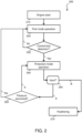
- FIG. 2 depicts a process flow 200 illustrating an example operation of a dual actuator hydraulic pitch-lock propeller system 100 according one or more embodiments.
- the process flow 200 begins at block 210, where an engine start is performed.
- An engine start can include a built in test to decrease pitch and verify integrity of the system 100. Note that the built in test can be performed in a protection mode momentarily to ensure a pressure developed is within a normal range expected. With a successful engine start (and an expected pressure is reached), the process flow 200 proceeds to block 220.
- the system 100 operates in a first mode.
- the first mode results in the normal operation of the propellers.
- the second section 123 of the valve 120 is positioned such that PCOURCE 132 is provided directly to the primary and protection actuators 111 and 112.
- the system 100 determines whether a control loss is detected.
- Control loss includes when a PCOURCE 132 is operating outside of expectations, whether due to an increase or decrease of pressure (e.g., hydraulic pressure is lost).
- a control loss can be detected by the monitoring of the sensor 150 or if a pitch position is not following a command. Further, the control loss can include when a loss of power occurs. If no control loss is detected, the process flow 200 returns to block 220 (as indicated by the No arrow). If the control loss is detected, the process flow 200 proceeds to block 240 (as indicated by the Yes arrow).
- the system 100 operates in a protection mode.
- a command can be sent to the valve 120 to enter the protection mode, which will cause the primary and protection actuators 111 and 112 to hold pitch (e.g., at a minimum inflight angle) due to the check valve 115 and 116.
- the system 100 can receive an input.
- the controller 140 can receive an input from a pilot of an aircraft.
- the input can direct the system 100 to continue operating in the protection mode.
- the process flow 200 proceeds to block 240 (as indicated by A arrows).
- the system 100 can default to continue operating in the protection mode.
- the system 100 can perform a pressure recover check (as shown by block 250). That is, if the control loss is still detected, then the process flow 200 proceeds to block 240 and the system 100 remains in the protection mode. However, if pressure has recovered, as detected by the sensor 150, then the system 100 can return to the first mode of operation. In this case, the process flow 200 proceeds to block 220 (as indicated by Yes arrow).
Landscapes
- Engineering & Computer Science (AREA)
- Aviation & Aerospace Engineering (AREA)
- Fluid-Pressure Circuits (AREA)
Claims (12)
- System, umfassend:einen Doppelkolbenaktuator, der dazu konfiguriert ist, im Einsatz eine Steigung von Propellern eines Luftfahrzeugs zu steuern, umfassend einen Primäraktuator (111) und einen Schutzaktuator (112),wobei im Einsatz der Primäraktuator und der Schutzaktuator dazu konfiguriert sind, sich zu bewegen, um eine Steigung der Propeller eines Luftfahrzeugs als Reaktion auf eine Zufuhr eines ersten und eines zweiten Mediums zu erhöhen oder zu verringern; undeine Vielzahl von Ventilen, die ein erstes Rückschlagventil (115), ein zweites Rückschlagventil (116) und ein drittes Ventil (120) umfasst,wobeidas dritte Ventil dazu konfiguriert ist, basierend auf einem Drucksignal von einem Sensor zwischen einem ersten Modus und einem Schutzmodus betrieben zu werden, der zu einem Zustand einer hydraulischen Steigungsverriegelung mit einer Fähigkeit, die Steigung der Propeller zu erhöhen, führt,wobei beim Betrieb in dem ersten Modus das zweite Medium durch das dritte Ventil direkt zu dem Primäraktuator und dem Schutzaktuator geleitet wird, ohne durch das erste bzw. das zweite Rückschlagventil zu fließen, wobei beim Betrieb in dem Schutzmodus das dritte Ventil derart angeordnet ist, dass das dritte Ventil das zweite Medium zu dem Primäraktuator und dem Schutzaktuator durch das erste bzw. zweite Rückschlagventil leitet, die es den Aktuatoren ermöglichen, die Steigung zu halten.
- System nach Anspruch 1, wobei das erste Medium eine hydraulische Kraft ausübt, die verwendet wird, um die Steigung der Propeller zu verringern.
- System nach Anspruch 1 oder 2, wobei das zweite Medium eine hydraulische Kraft ausübt, die verwendet wird, um die Steigung der Propeller zu erhöhen.
- System nach einem der vorhergehenden Ansprüche, wobei eine Verbindung des Schutzaktuators atmosphärischen Druck oder das erste Medium empfängt.
- System nach einem der vorhergehenden Ansprüche, wobei das dritte Ventil (120) ein magnetisch betätigtes Ventil umfasst, das ein gesteuertes Magnetfeld erzeugt, das eine auf das dritte Ventil wirkende Kraft bereitstellt.
- System nach einem der Ansprüche 1 bis 4, wobei das dritte Ventil eine Vorspannfeder umfasst, um den Schutzmodus während eines Leistungsverlusts auszuwählen.
- Verfahren, umfassend:Betreiben eines Doppelkolbenaktuators in einem ersten Modus, wobei der Doppelkolbenaktuator einen Primäraktuator (111) und einen Schutzaktuator (112) umfasst, die sich bewegen, um eine Steigung von Propellern eines Luftfahrzeugs als Reaktion auf eine Zufuhr eines ersten und eines zweiten Mediums zu erhöhen und zu verringern, ohne dass das erste Medium und das zweite Medium durch ein erstes Rückschlagventil oder ein zweites Rückschlagventil fließen; undErkennen eines Steuerungsverlusts in Bezug auf das zweite Medium basierend auf einem Drucksignal von einem Drucksensor und Umschalten eines dritten Ventils zwischen dem Betrieb in dem ersten Modus und einem Schutzmodus, der zu einem Zustand einer hydraulischen Steigungsverriegelung mit einer Fähigkeit führt, die Steigung der Propeller basierend auf dem Steuerungsverlust zu erhöhen, wobei beim Betrieb des Doppelkolbenaktuators in dem Schutzmodus das dritte Ventil das zweite Medium zu dem Primäraktuator und dem Schutzaktuator durch das erste und das zweite Rückschlagventil (115, 116) leitet, die es den Aktuatoren ermöglichen, die Steigung zu halten.
- Verfahren nach Anspruch 7, wobei ein Sensor (150) den Doppelkolbenaktuator auf den Steuerungsverlust überwacht.
- Verfahren nach Anspruch 7 oder 8, wobei der Schutzmodus einen Zustand einer hydraulischen Steigungsverriegelung mit einer Fähigkeit, die Steigung der Propeller des Luftfahrzeugs zu erhöhen, umfasst.
- Verfahren nach Anspruch 7, 8 oder 9, wobei der Primäraktuator und der Schutzaktuator die Propeller des Luftfahrzeugs gemäß der Zufuhr des ersten und des zweiten Mediums steuern und das erste Medium eine hydraulische Kraft ausübt, die verwendet wird, um die Steigung der Propeller zu verringern.
- Verfahren nach Anspruch 7, 8 oder 9, wobei der Primäraktuator und der Schutzaktuator die Propeller des Luftfahrzeugs gemäß der Zufuhr des ersten und des zweiten Mediums steuern und das zweite Medium eine hydraulische Kraft ausübt, die verwendet wird, um die Steigung der Propeller zu erhöhen.
- Verfahren nach einem der Ansprüche 7 bis 11, wobei das dritte Ventil ein magnetisch betätigtes Ventil umfasst, das ein gesteuertes Magnetfeld erzeugt, das eine auf das dritte Ventil wirkende Kraft bereitstellt, oder wobei das dritte Ventil eine Vorspannfeder umfasst, um den Schutzmodus während eines Leistungsverlusts auszuwählen.
Applications Claiming Priority (1)
| Application Number | Priority Date | Filing Date | Title |
|---|---|---|---|
| US16/566,023 US11097832B2 (en) | 2019-09-10 | 2019-09-10 | Dual actuator hydraulic pitch-lock propeller system |
Publications (2)
| Publication Number | Publication Date |
|---|---|
| EP3792178A1 EP3792178A1 (de) | 2021-03-17 |
| EP3792178B1 true EP3792178B1 (de) | 2025-02-12 |
Family
ID=72470297
Family Applications (1)
| Application Number | Title | Priority Date | Filing Date |
|---|---|---|---|
| EP20195518.4A Active EP3792178B1 (de) | 2019-09-10 | 2020-09-10 | Hydraulisches steigungsverriegelungspropellersystem mit zwei aktuatoren |
Country Status (2)
| Country | Link |
|---|---|
| US (1) | US11097832B2 (de) |
| EP (1) | EP3792178B1 (de) |
Families Citing this family (3)
| Publication number | Priority date | Publication date | Assignee | Title |
|---|---|---|---|---|
| US12466545B2 (en) * | 2022-11-08 | 2025-11-11 | Pratt & Whitney Canada Corp. | Systems and methods for controlling propeller control unit fluid pressure |
| IT202300000423A1 (it) | 2023-01-13 | 2024-07-13 | Ge Avio Srl | Sistema di bloccaggio del passo |
| US12060812B1 (en) | 2023-03-16 | 2024-08-13 | General Electric Company | Turbo engine having blade pitch actuation system for variable pitch fan |
Family Cites Families (12)
| Publication number | Priority date | Publication date | Assignee | Title |
|---|---|---|---|---|
| US2980188A (en) | 1958-11-14 | 1961-04-18 | United Aircraft Corp | Combined feathering and pitch lock system |
| US3689103A (en) * | 1970-11-27 | 1972-09-05 | Pneumo Dynamics Corp | Variable height vehicle suspension |
| US4591313A (en) | 1983-12-30 | 1986-05-27 | The Boeing Company | Propeller pitch control system and apparatus |
| US5174718A (en) | 1991-08-12 | 1992-12-29 | United Technologies Corporation | Blade pitch change control system |
| US6261062B1 (en) * | 2000-01-17 | 2001-07-17 | Brunswick Corporation | Actuation system for a controllable pitch propeller |
| US8545178B2 (en) | 2006-03-08 | 2013-10-01 | Hamilton Sundstrand Corporation | Controlled propeller pitch lock actuation system |
| GB0821239D0 (en) | 2008-11-21 | 2008-12-31 | Rolls Royce Plc | A machine such as a gas turbine |
| GB201000054D0 (en) | 2010-01-05 | 2010-02-17 | Rolls Royce Plc | Propeller assembly pitch change apparatus |
| GB201007565D0 (en) | 2010-05-06 | 2010-06-23 | Rolls Royce Plc | Pitch control mechanism |
| US8966891B2 (en) * | 2011-09-30 | 2015-03-03 | Caterpillar Inc. | Meterless hydraulic system having pump protection |
| US10683082B2 (en) * | 2016-04-29 | 2020-06-16 | Ratier-Figeac Sas | Hydraulic actuation systems |
| US10577080B2 (en) | 2017-08-23 | 2020-03-03 | Hamilton Sundstrand Corporation | Dual valve systems for actuator control |
-
2019
- 2019-09-10 US US16/566,023 patent/US11097832B2/en active Active
-
2020
- 2020-09-10 EP EP20195518.4A patent/EP3792178B1/de active Active
Also Published As
| Publication number | Publication date |
|---|---|
| US20210070425A1 (en) | 2021-03-11 |
| EP3792178A1 (de) | 2021-03-17 |
| US11097832B2 (en) | 2021-08-24 |
Similar Documents
| Publication | Publication Date | Title |
|---|---|---|
| EP3792178B1 (de) | Hydraulisches steigungsverriegelungspropellersystem mit zwei aktuatoren | |
| US11827336B2 (en) | Propeller blade angle closed loop control by solenoid modulation | |
| EP3447315B1 (de) | Doppelventilsysteme zur steuerung eines stellgliedes | |
| US5897293A (en) | Counterweighted propeller control system | |
| US8505848B2 (en) | Aircraft actuator hydraulic system | |
| GB2196588A (en) | Rudder control arrangement for aircraft | |
| EP3543115B1 (de) | Verteilte hinterkantenflügelklappensysteme | |
| US10940939B2 (en) | Ground spoiler control architecture for aircraft | |
| EP3708449B1 (de) | Primäres bremsregelsystem mit abwechselnder fahrzeugsystemüberbrückung | |
| JP5391086B2 (ja) | 飛行制御システム | |
| US6206329B1 (en) | Process and device for the control of the rudder of an aircraft | |
| WO2001005654A2 (en) | Vehicle control system and method using a control surface and a geared tab | |
| US20100318245A1 (en) | Flight control system | |
| KR101951642B1 (ko) | 유무인항공기용 구동드라이브 구조 이중화 장치 | |
| US11993362B2 (en) | Dual-concentric control valve with direct drive control and failed motor protection | |
| US11305787B2 (en) | Vehicle control system for autonomous, remotely-controlled, or manual operation of a vehicle | |
| CN112208745B (zh) | 液压致动系统 | |
| US20260021884A1 (en) | Electronic unit for a tactile cueing apparatus | |
| EP2341252B1 (de) | Luftfahrzeug | |
| EP4306431A1 (de) | Elektronische einheit für ein taktiles hinweisgerät | |
| GB2620633A (en) | An electronic unit for a tactile cueing apparatus | |
| FR2872483A1 (fr) | Dispositif de detection de defaillance de la voie principale de transmission d'effort pour actionneurs de commande de vol a double voie de transmission d'effort |
Legal Events
| Date | Code | Title | Description |
|---|---|---|---|
| PUAI | Public reference made under article 153(3) epc to a published international application that has entered the european phase |
Free format text: ORIGINAL CODE: 0009012 |
|
| STAA | Information on the status of an ep patent application or granted ep patent |
Free format text: STATUS: THE APPLICATION HAS BEEN PUBLISHED |
|
| AK | Designated contracting states |
Kind code of ref document: A1 Designated state(s): AL AT BE BG CH CY CZ DE DK EE ES FI FR GB GR HR HU IE IS IT LI LT LU LV MC MK MT NL NO PL PT RO RS SE SI SK SM TR |
|
| AX | Request for extension of the european patent |
Extension state: BA ME |
|
| STAA | Information on the status of an ep patent application or granted ep patent |
Free format text: STATUS: REQUEST FOR EXAMINATION WAS MADE |
|
| 17P | Request for examination filed |
Effective date: 20210917 |
|
| RBV | Designated contracting states (corrected) |
Designated state(s): AL AT BE BG CH CY CZ DE DK EE ES FI FR GB GR HR HU IE IS IT LI LT LU LV MC MK MT NL NO PL PT RO RS SE SI SK SM TR |
|
| STAA | Information on the status of an ep patent application or granted ep patent |
Free format text: STATUS: EXAMINATION IS IN PROGRESS |
|
| 17Q | First examination report despatched |
Effective date: 20221212 |
|
| GRAP | Despatch of communication of intention to grant a patent |
Free format text: ORIGINAL CODE: EPIDOSNIGR1 |
|
| STAA | Information on the status of an ep patent application or granted ep patent |
Free format text: STATUS: GRANT OF PATENT IS INTENDED |
|
| INTG | Intention to grant announced |
Effective date: 20240916 |
|
| GRAS | Grant fee paid |
Free format text: ORIGINAL CODE: EPIDOSNIGR3 |
|
| GRAA | (expected) grant |
Free format text: ORIGINAL CODE: 0009210 |
|
| STAA | Information on the status of an ep patent application or granted ep patent |
Free format text: STATUS: THE PATENT HAS BEEN GRANTED |
|
| AK | Designated contracting states |
Kind code of ref document: B1 Designated state(s): AL AT BE BG CH CY CZ DE DK EE ES FI FR GB GR HR HU IE IS IT LI LT LU LV MC MK MT NL NO PL PT RO RS SE SI SK SM TR |
|
| REG | Reference to a national code |
Ref country code: GB Ref legal event code: FG4D |
|
| REG | Reference to a national code |
Ref country code: CH Ref legal event code: EP |
|
| REG | Reference to a national code |
Ref country code: DE Ref legal event code: R096 Ref document number: 602020045830 Country of ref document: DE |
|
| REG | Reference to a national code |
Ref country code: IE Ref legal event code: FG4D |
|
| REG | Reference to a national code |
Ref country code: NL Ref legal event code: MP Effective date: 20250212 |
|
| PG25 | Lapsed in a contracting state [announced via postgrant information from national office to epo] |
Ref country code: RS Free format text: LAPSE BECAUSE OF FAILURE TO SUBMIT A TRANSLATION OF THE DESCRIPTION OR TO PAY THE FEE WITHIN THE PRESCRIBED TIME-LIMIT Effective date: 20250512 |
|
| PG25 | Lapsed in a contracting state [announced via postgrant information from national office to epo] |
Ref country code: FI Free format text: LAPSE BECAUSE OF FAILURE TO SUBMIT A TRANSLATION OF THE DESCRIPTION OR TO PAY THE FEE WITHIN THE PRESCRIBED TIME-LIMIT Effective date: 20250212 |
|
| PG25 | Lapsed in a contracting state [announced via postgrant information from national office to epo] |
Ref country code: PL Free format text: LAPSE BECAUSE OF FAILURE TO SUBMIT A TRANSLATION OF THE DESCRIPTION OR TO PAY THE FEE WITHIN THE PRESCRIBED TIME-LIMIT Effective date: 20250212 |
|
| PG25 | Lapsed in a contracting state [announced via postgrant information from national office to epo] |
Ref country code: ES Free format text: LAPSE BECAUSE OF FAILURE TO SUBMIT A TRANSLATION OF THE DESCRIPTION OR TO PAY THE FEE WITHIN THE PRESCRIBED TIME-LIMIT Effective date: 20250212 |
|
| REG | Reference to a national code |
Ref country code: LT Ref legal event code: MG9D |
|
| PG25 | Lapsed in a contracting state [announced via postgrant information from national office to epo] |
Ref country code: IS Free format text: LAPSE BECAUSE OF FAILURE TO SUBMIT A TRANSLATION OF THE DESCRIPTION OR TO PAY THE FEE WITHIN THE PRESCRIBED TIME-LIMIT Effective date: 20250612 Ref country code: NO Free format text: LAPSE BECAUSE OF FAILURE TO SUBMIT A TRANSLATION OF THE DESCRIPTION OR TO PAY THE FEE WITHIN THE PRESCRIBED TIME-LIMIT Effective date: 20250512 |
|
| PG25 | Lapsed in a contracting state [announced via postgrant information from national office to epo] |
Ref country code: NL Free format text: LAPSE BECAUSE OF FAILURE TO SUBMIT A TRANSLATION OF THE DESCRIPTION OR TO PAY THE FEE WITHIN THE PRESCRIBED TIME-LIMIT Effective date: 20250212 |
|
| PG25 | Lapsed in a contracting state [announced via postgrant information from national office to epo] |
Ref country code: HR Free format text: LAPSE BECAUSE OF FAILURE TO SUBMIT A TRANSLATION OF THE DESCRIPTION OR TO PAY THE FEE WITHIN THE PRESCRIBED TIME-LIMIT Effective date: 20250212 |
|
| PG25 | Lapsed in a contracting state [announced via postgrant information from national office to epo] |
Ref country code: LV Free format text: LAPSE BECAUSE OF FAILURE TO SUBMIT A TRANSLATION OF THE DESCRIPTION OR TO PAY THE FEE WITHIN THE PRESCRIBED TIME-LIMIT Effective date: 20250212 Ref country code: PT Free format text: LAPSE BECAUSE OF FAILURE TO SUBMIT A TRANSLATION OF THE DESCRIPTION OR TO PAY THE FEE WITHIN THE PRESCRIBED TIME-LIMIT Effective date: 20250612 |
|
| PG25 | Lapsed in a contracting state [announced via postgrant information from national office to epo] |
Ref country code: BG Free format text: LAPSE BECAUSE OF FAILURE TO SUBMIT A TRANSLATION OF THE DESCRIPTION OR TO PAY THE FEE WITHIN THE PRESCRIBED TIME-LIMIT Effective date: 20250212 Ref country code: GR Free format text: LAPSE BECAUSE OF FAILURE TO SUBMIT A TRANSLATION OF THE DESCRIPTION OR TO PAY THE FEE WITHIN THE PRESCRIBED TIME-LIMIT Effective date: 20250513 |
|
| REG | Reference to a national code |
Ref country code: AT Ref legal event code: MK05 Ref document number: 1765851 Country of ref document: AT Kind code of ref document: T Effective date: 20250212 |
|
| PG25 | Lapsed in a contracting state [announced via postgrant information from national office to epo] |
Ref country code: SE Free format text: LAPSE BECAUSE OF FAILURE TO SUBMIT A TRANSLATION OF THE DESCRIPTION OR TO PAY THE FEE WITHIN THE PRESCRIBED TIME-LIMIT Effective date: 20250212 |
|
| PG25 | Lapsed in a contracting state [announced via postgrant information from national office to epo] |
Ref country code: SM Free format text: LAPSE BECAUSE OF FAILURE TO SUBMIT A TRANSLATION OF THE DESCRIPTION OR TO PAY THE FEE WITHIN THE PRESCRIBED TIME-LIMIT Effective date: 20250212 |
|
| PG25 | Lapsed in a contracting state [announced via postgrant information from national office to epo] |
Ref country code: DK Free format text: LAPSE BECAUSE OF FAILURE TO SUBMIT A TRANSLATION OF THE DESCRIPTION OR TO PAY THE FEE WITHIN THE PRESCRIBED TIME-LIMIT Effective date: 20250212 |
|
| PGFP | Annual fee paid to national office [announced via postgrant information from national office to epo] |
Ref country code: DE Payment date: 20250820 Year of fee payment: 6 |
|
| PG25 | Lapsed in a contracting state [announced via postgrant information from national office to epo] |
Ref country code: IT Free format text: LAPSE BECAUSE OF FAILURE TO SUBMIT A TRANSLATION OF THE DESCRIPTION OR TO PAY THE FEE WITHIN THE PRESCRIBED TIME-LIMIT Effective date: 20250212 |
|
| PGFP | Annual fee paid to national office [announced via postgrant information from national office to epo] |
Ref country code: GB Payment date: 20250820 Year of fee payment: 6 |
|
| PG25 | Lapsed in a contracting state [announced via postgrant information from national office to epo] |
Ref country code: AT Free format text: LAPSE BECAUSE OF FAILURE TO SUBMIT A TRANSLATION OF THE DESCRIPTION OR TO PAY THE FEE WITHIN THE PRESCRIBED TIME-LIMIT Effective date: 20250212 |
|
| PGFP | Annual fee paid to national office [announced via postgrant information from national office to epo] |
Ref country code: FR Payment date: 20250820 Year of fee payment: 6 |
|
| PG25 | Lapsed in a contracting state [announced via postgrant information from national office to epo] |
Ref country code: EE Free format text: LAPSE BECAUSE OF FAILURE TO SUBMIT A TRANSLATION OF THE DESCRIPTION OR TO PAY THE FEE WITHIN THE PRESCRIBED TIME-LIMIT Effective date: 20250212 Ref country code: CZ Free format text: LAPSE BECAUSE OF FAILURE TO SUBMIT A TRANSLATION OF THE DESCRIPTION OR TO PAY THE FEE WITHIN THE PRESCRIBED TIME-LIMIT Effective date: 20250212 |
|
| PG25 | Lapsed in a contracting state [announced via postgrant information from national office to epo] |
Ref country code: RO Free format text: LAPSE BECAUSE OF FAILURE TO SUBMIT A TRANSLATION OF THE DESCRIPTION OR TO PAY THE FEE WITHIN THE PRESCRIBED TIME-LIMIT Effective date: 20250212 |
|
| PG25 | Lapsed in a contracting state [announced via postgrant information from national office to epo] |
Ref country code: SK Free format text: LAPSE BECAUSE OF FAILURE TO SUBMIT A TRANSLATION OF THE DESCRIPTION OR TO PAY THE FEE WITHIN THE PRESCRIBED TIME-LIMIT Effective date: 20250212 |
|
| REG | Reference to a national code |
Ref country code: DE Ref legal event code: R097 Ref document number: 602020045830 Country of ref document: DE |
|
| PLBE | No opposition filed within time limit |
Free format text: ORIGINAL CODE: 0009261 |
|
| STAA | Information on the status of an ep patent application or granted ep patent |
Free format text: STATUS: NO OPPOSITION FILED WITHIN TIME LIMIT |
|
| 26N | No opposition filed |
Effective date: 20251113 |