EP3792425B1 - Einsatz für einen wesentlichen bestandteil eines bauwerks - Google Patents
Einsatz für einen wesentlichen bestandteil eines bauwerks Download PDFInfo
- Publication number
- EP3792425B1 EP3792425B1 EP20195510.1A EP20195510A EP3792425B1 EP 3792425 B1 EP3792425 B1 EP 3792425B1 EP 20195510 A EP20195510 A EP 20195510A EP 3792425 B1 EP3792425 B1 EP 3792425B1
- Authority
- EP
- European Patent Office
- Prior art keywords
- insert
- box
- cavity
- shaft
- orifice
- Prior art date
- Legal status (The legal status is an assumption and is not a legal conclusion. Google has not performed a legal analysis and makes no representation as to the accuracy of the status listed.)
- Active
Links
Images

Classifications
-
- E—FIXED CONSTRUCTIONS
- E04—BUILDING
- E04F—FINISHING WORK ON BUILDINGS, e.g. STAIRS, FLOORS
- E04F13/00—Coverings or linings, e.g. for walls or ceilings
- E04F13/07—Coverings or linings, e.g. for walls or ceilings composed of covering or lining elements; Sub-structures therefor; Fastening means therefor
- E04F13/08—Coverings or linings, e.g. for walls or ceilings composed of covering or lining elements; Sub-structures therefor; Fastening means therefor composed of a plurality of similar covering or lining elements
- E04F13/0801—Separate fastening elements
- E04F13/0803—Separate fastening elements with load-supporting elongated furring elements between wall and covering elements
- E04F13/081—Separate fastening elements with load-supporting elongated furring elements between wall and covering elements with additional fastening elements between furring elements and covering elements
- E04F13/0816—Separate fastening elements with load-supporting elongated furring elements between wall and covering elements with additional fastening elements between furring elements and covering elements the additional fastening elements extending into the back side of the covering elements
-
- E—FIXED CONSTRUCTIONS
- E04—BUILDING
- E04F—FINISHING WORK ON BUILDINGS, e.g. STAIRS, FLOORS
- E04F13/00—Coverings or linings, e.g. for walls or ceilings
- E04F13/07—Coverings or linings, e.g. for walls or ceilings composed of covering or lining elements; Sub-structures therefor; Fastening means therefor
- E04F13/08—Coverings or linings, e.g. for walls or ceilings composed of covering or lining elements; Sub-structures therefor; Fastening means therefor composed of a plurality of similar covering or lining elements
- E04F13/14—Coverings or linings, e.g. for walls or ceilings composed of covering or lining elements; Sub-structures therefor; Fastening means therefor composed of a plurality of similar covering or lining elements stone or stone-like materials, e.g. ceramics concrete; of glass or with an outer layer of stone or stone-like materials or glass
Definitions
- the present invention relates to an insert for a constituent element of a construction, preferably a facade panel.
- a facade panel of a construction comprises a connecting piece inserted into the panel intended to hook an anchoring device to fix the panel to a wall of the construction.
- the connecting piece comprises two fixed metal elements which are arranged in parallel, each comprising a portion embedded and/or buried within the building material constituting the facade panel, and a semi-annular portion configured to accommodate and stabilize one end of a pin.
- This pin serves as a support for a fixing device called a “mounting system”.
- the latter comprises a metal bar, one end of which is folded over on itself to form a ring surrounding the pin. At the other end of the metal bar is inserted a plate.
- the latter is attached to the wall of the construction (for example, via an anchor or any other suitable means).
- a metal lath being welded to one of said two fixed metal elements is then pushed, for example with a hammer, against the pin and one of the semi-annular portions so as to ensure that this pin remains in place.
- the connecting piece must be fixed and inserted and/or embedded in the construction material constituting the facade panel while allowing the semi-annular portions to be accessible to insert the pin therein. This is the reason why it is known to at least partially enclose these semi-annular portions in a block of expanded polystyrene which extends the edges of the front panel. Thus, when fixing the front panel on site, it suffices for a site worker to scrape the expanded polystyrene by means of a scraper (or any other suitable means) so as to release the semi-annular portions and insert the pin previously surrounded in the end of the metal bar folded on itself.
- Said connecting piece, said metal slat and said expanded polystyrene block form an insert of the front panel for its attachment to the construction.
- This insert and its use as described nevertheless have several disadvantages.
- First, performing the assembly process of the mounting system and the pin with the insert is complex and time consuming.
- the time required to release the semi-annular portions of the expanded polystyrene is significant. It also happens that you have to make several attempts before correctly placing the pin between the two semi-annular portions.
- the use of the insert is not ecological. Indeed, it requires scraping expanded polystyrene which then flies away on the construction site and disperses in nature.
- the polystyrene block has a fragile behavior and risks deteriorating during transport or their implementation, which can make assembly of the pin impossible.
- connection system arranged in a recess of the front panel and comprising a connection piece comparable to that described above, maintaining a kind of pin by its ends.
- the latter are of a particular shape and are riveted at the level of the semi-annular portions.
- An eyelet surrounds this pin and can slide in a determined position along it.
- the eyelet accommodates a clamping screw, which facilitates subsequent attachment of the front panel using a mounting system.
- this connection system remains complex to assemble on site or beforehand during the manufacture of the facade panel.
- the existence of the recess complicates the manufacture of the front panel.
- the use of an expanded polystyrene block as described above appears to be necessary to fill the recess while allowing safe handling of the facade panel.
- Requirement DE3608953A1 discloses such a connection system arranged in a recess of the facade panel improved compared to that of the patent AT370471B , and this by a partial substitution of the pin and the connecting piece by a support pin projecting from two sides of the recess.
- the recess is created by inserting a rigid plastic foam. Discs are to be provided laterally to fix the support axis to this foam during the manufacture of the front panel.
- the support shaft is formed, for its part, of several parts cooperating mechanically together. This system nevertheless reproduces the defects of the connection systems of the prior art in terms of complexity in the manufacture of the connection system itself and of the facade panel, as well as in its use on site.
- An object of the present invention is to provide an insert for a constituent element of a construction, for example a facade panel, which is simpler, faster and more ecological to manufacture and to use.
- the insert according to the invention is both simpler, faster and more ecological to manufacture and to use, in particular for fixing a facade panel to a construction. Indeed, with regard to the prior art described, it is no longer necessary to at least partially enclose a connecting piece in a block of expanded polystyrene because the box plays this role during the manufacture of the constituent element of building. It is then sufficient to open and/or break the box on a construction site (if it is not partially open) to access the connecting piece, which is simpler, faster and more ecological given the wide range of materials that are both manageable and ecological from which it can be made.
- the box therefore makes it possible to facilitate the manufacture of the front panel and the use of the insert, while making it possible to directly and simply support the axis without requiring the provision of a complex assembly of a pin with a connection system such as described in the prior art.
- the insert according to the present invention further provides a connection piece which allows simple and rapid connection (preferably a male-female connection) with a fixing and/or anchoring device.
- the metal bar can cooperate directly with the part of connection.
- the connecting piece is tubular, the metal bar can be inserted therein, for example, by screwing and/or by clipping.
- the connecting piece can also rotate around the axis, it is also possible to adjust the orientation of the fixing and/or anchoring device with respect to the constituent element of a construction comprising the insert.
- the pin and its mechanical coupling with the connecting piece are very advantageously provided in the insert, which makes it possible to simply and effectively replace the pin mounting system of the prior art and to eliminate the site steps necessary for its installation. placement.
- the insert according to the present invention allows a small number and little complexity of the various operations necessary on site.
- these operations and/or the method of using the insert according to the invention comprise (and, preferably, consist of): opening the box (if it is closed) to access the connecting piece , rotate the latter around the axis, cause a fixing and/or anchoring device to cooperate with the connecting piece (for example, by screwing and/or clipping).
- This insert is therefore simple and quick to use, with no significant ecological impact.
- the box can be made of at least one recyclable or recycled material which is ecological and respectful of and/or not harmful to the environment, unlike expanded polystyrene particles.
- a material consists, for example, of wood and/or plastic.
- the box is made of recycled plastic.
- the box and/or the cavity are optionally preferably parallelepipedic, which can facilitate the design of the box. In general, such a box is easy, quick and inexpensive to manufacture. It generates little waste and additional weight to the insert, and therefore to the constituent element of the construction.
- the box comprises a code, for example, a color, on an external face making it possible to visually identify the type of constituent element of construction for which the insert is intended.
- the box is delivered completely closed, the connecting piece then being completely arranged in the cavity.
- the cavity is therefore completely delimited by the box upon delivery of the constituent element of the construction. It is indeed easier to design such an element from a cast and solidified construction material such as concrete by embedding the closed box therein.
- the closure of the box guarantees that the connecting piece will remain in the cavity during all the stages of manufacture of the element and its transport to the site, without protruding from one face of the element. It is indeed advantageous for the transport and storage of such elements that no part protrudes because it could break and/or complicate the storage and/or transport, as well as the placement of these elements on site.
- the box also preferably comprises removable and/or slidable side reinforcements arranged to hold the connecting piece in a fixed position in the cavity.
- the opening and/or the orifice communicates with the cavity.
- the connecting piece is preferably completely arranged in the cavity (when the box is closed), this embodiment being prior to the use of the insert on site.
- the means of access to the cavity is able to close the box so that the latter completely delimits the cavity, the connecting piece being completely arranged in the cavity when the box is closed.
- the opening is preferably pre-existing in the sense that it is made in the box, for example, during manufacture of the box, and then covered by a lid.
- the cover is preferably a face portion (preferably one face) of the box screwed and/or clipped and/or slid onto the contour of the opening of the box and/or onto the side edges of the box (for example, by means of screws and/or reliefs dug on an external face of the box), so that it is easy to move and/or slide on site.
- the box includes hinges mechanically coupled to the cover to allow it to pivot around an axis or a fulcrum.
- any type of cover and/or any type of stabilization of the cover on the opening known can be used within the scope of this invention.
- the outer wall preferably consists of a face portion (preferably, a face) of the box which is thinner than the rest of the box and/or which is made of a material of low solidity and/or which is membraned, so that it is very easy to break and/or break by means of a construction tool, for example, a hammer and/or a knife, from the outside of the box, so as to release an opening of the box.
- a construction tool for example, a hammer and/or a knife
- the box can be made homogeneously, without the structure of the wall referred to in (b) being distinguished in any particular way from the rest of the box.
- any face of the box preferably consists of a wall that can easily be broken off with a construction tool.
- the box comprises two plastic half-shells fitting one inside the other to define the cavity, one of these two half-shells being made of a plastic thinner and/or more fragile than the other, so that it constitutes said breakable outer wall.
- this half-shell can optionally also be assimilated to a removable lid of the box.
- said opening is preferably large enough for several fingers of one hand, preferably one hand, to be able to pass through it, so as to easily manipulate the connecting piece in the cavity .
- the opening is preferably larger than a disc 5 centimeters in diameter.
- Means of access other than those mentioned in (a) and (b) can be fully used within the scope of the invention.
- such a means of access will include the existence or the possibility of creating such an opening.
- the box includes means of access to the cavity so that, once delivered to the site, the box can be broken and/or opened to gain access to the part connection.
- the box is capable of rotating around the axis, it is then possible to arrange it so as to connect and/or mechanically couple an anchoring device.
- the box comprises an opening (for example, the one which was covered by a lid that the 'one has moved (case (a)) or that which has been practiced by breaking the wall (case (b)), and / or the connecting piece extends partially out of the cavity, through the opening.
- the connecting piece preferably extends transversely to the axis, more preferably perpendicular to the axis.
- an angle between a direction of extension of the connecting piece perpendicular to the axis and a vertical direction perpendicular to the axis varies by at most 200°.
- the connecting piece can rotate around the axis, within the limits of the box.
- This angle gives enough freedom to make this adjustment.
- the angle is preferably between 15° and 25° when the facade panel is fixed to the facade (and therefore when the anchoring device connected and/or secured and/or mechanically coupled to the insert is adjusted to an anchor point on the facade).
- This connecting piece is more preferably adapted to secure an anchoring and/or fastening device (for example, a mounting system) configured to suspend the constituent element from the construction, preferably consisting of a facade panel.
- an anchoring and/or fastening device for example, a mounting system
- the connecting piece is preferably tubular. It preferably comprises a threaded internal part. These embodiments are preferably combined.
- the existence of a threaded internal part is very advantageous. Indeed, thanks to the internal threaded part of the connecting part, it is possible to secure a threaded male part of suitable dimensions, for example a threaded rod in the preferred case where the connecting part is tubular, by simply screwing it and quickly in the internal threaded part.
- an anchoring device can thus be used which comprises a threaded rod in a first end part fixed to means for suspending and/or fixing to the construction arranged in a second end part.
- Such a female rod preferably comprises a threaded internal part.
- This embodiment clarifies a preferred mechanical coupling between the pin and the connecting piece, the latter forming an integral part of a yoke intended to receive the pin to produce the pivot connection (that is to say a connection to one degree of freedom, this being the rotation of the yoke around the axis).
- Said orifice is preferably bordered by a symmetrical U-shape of a plate of the yoke, the female rod being held between the two branches of the U by welding. It is advantageous to use a screed as described because it is quite easy and inexpensive to manufacture.
- the connecting piece can be a nut or a threaded female sleeve preferably welded to such a U-shaped plate.
- a “component element of a construction” refers to a part of a construction, for example, part of a wall, a wall, a block, a panel, etc.
- a facade panel intended to be arranged and/or hung and/or suspended on and/or facing a facade of a support structure, for example a wall of a building.
- Such a facade panel extends essentially over a surface defining this facade, and has a thickness which is defined and measured perpendicular to the facade, preferably at least 3 centimeters to guarantee sufficient space to arrange and/or insert the insert according to the invention.
- a “face” of a façade panel designates a surface of this panel extending parallel to the façade, and a “slice” of a façade panel designates another surface of this panel extending essentially perpendicular to the facade.
- a facade panel preferably comprises two faces: a so-called “interior” face facing the support structure, generally invisible externally (therefore for an observer outside the construction), and a so-called “exterior” face opposite the interior face. , visible externally.
- the constituent element of the construction in question preferably consists of a cast and solidified construction material so that, during its manufacture, the insert is placed in a mold in which this construction material is cast.
- the latter is a concrete.
- the "construction” for which said element is intended is arbitrary. It can be, for example, a building with or without floor, a dam, a monument, ...
- a "box” preferably refers to a rigid container delimiting a cavity capable of accommodating goods, objects, various products. It can be made of a material, for example, wood, cardboard, metal, plastic, ... and / or a combination thereof.
- the term "cavity” preferably refers to an interior space of a solid body, in this case preferably the box.
- the term “box” must also be interpreted as being a means of defining the cavity during the production of the constituent element of the construction. In particular, any box which defines a cavity at least partially, so as to make possible the design of a constituent element of the construction falls within the scope of the present invention. It is in particular for this reason that it is not necessary for the cavity to be completely delimited by the box. It may be sufficient to consider a box that has only a few faces to be able to design the constituent element of the construction.
- an "axle” is preferably a mechanical axis, that is to say an elongated mechanical part making it possible to rotate another mechanical part on itself and/or to assemble parts together.
- the axis is preferably metallic and/or cylindrical.
- the axis is preferably a rod and/or a bar, preferably of constant diameter.
- the use of such a pin is easy and inexpensive within the scope of the invention. Its manufacture is also easy and can be made in a chain by cutting a long metal cylinder.
- the insert comprises a load take-up support capable of supporting and/or maintaining at least one metal bar external to the cavity.
- This load take-up support is preferably fixed to the axis and/or to the box. It plays an important role in the case where the constituent element of the construction is a facade panel, and where the insert is configured to accommodate a device for anchoring and/or fixing the facade panel to a facade of the building. . Indeed, in this case, the weight of the facade panel is transferred to the construction via the anchoring and/or fixing device and via the insert. It is therefore important that the weight of the facade panel is optimally transferred to the insert, more precisely to the axle and the connecting piece.
- metal bars which are supported and/or mechanically coupled by the axis via the load-bearing support, to advantageously take up the weight of the panel in an optimal manner according to the extension of these metal bars in the constituent element of the construction towards the axis.
- Such metal bars advantageously make it possible to take up a significant weight of a facade panel even for a facade panel of small thickness.
- the metal bars preferably form a sealing reinforcement for the constituent element of the construction. These are preferably high grip bars.
- each plate is easy and inexpensive. It can be carried out for example by cutting out a shape in a large sheet of material.
- the material constituting each plate is metallic. It is preferably the same material which constitutes the axis.
- each plate is placed against (one face of) the box.
- each plate is external to the cavity.
- each plate is welded (and therefore fixed) to the axis, preferably at the level of the central orifice.
- each plate is welded to the axis only by a spot weld, so that the insert either in one piece and can be inserted (for example, cast) into a construction material constituting the constituent element of the construction.
- the box comprises at least one lateral protrusion which preferably extends externally from an outer face of the box, preferably of cylindrical shape, and each plate comprises an opening for socket for connect the plate against the box by fitting such a lateral projection into the fitting hole of the plate, so that the insert is integral and can be inserted (for example, cast) into a construction material constituting the constituent element of the construction.
- Each plate is thus fixed to the box by such interlocking.
- Several such "fastening on / to the box” can be considered, for example, a simple clipping. The latter is also preferred.
- Each plate is preferably in simple direct contact with the axis, the latter passing through a central orifice of a top portion of the plate when the latter comprises one as described above.
- the box is particularly advantageous because, in addition to at least partially delimiting the cavity and supporting and maintaining the axis, it also makes it possible to easily attach each plate to the outside of the cavity.
- each lateral protrusion optionally passes completely through an interlocking orifice of a plate, one end of the lateral protrusion being then heated and/or melted, and then pressed against the plate so as to form a rivet which ensures a good fixing of the plate against the box (without the need either for welding (or more generally for fixing) of the plate with the axis as proposed in the first sub-embodiment).
- a less skilled worker unqualified to weld, for example
- each pair of a lateral protrusion and a corresponding interlocking orifice by interlocking is advantageously configured to allow a worker to avoid any error in mounting the plates on the box.
- the plates are preferably of a particular, non-symmetrical shape, as discussed below and faithfully illustrated in the figures introduced below.
- a nesting orifice and an associated lateral protrusion are therefore preferably of a specific shape (more preferably adapted to fixing by clipping) so as to correspond only to each other, and to only allow a connection of a plate on the box only in a certain orientation of the plate.
- the position of the interlocking orifice on the plate is preferably also chosen for this latter purpose. It is therefore not possible to connect a plate to such a lateral protrusion by one of the orifices provided to receive a metal bar, nor to connect the plate in an unsuitable orientation against the box.
- each plate comprising feet and a top portion
- the specific shape of each plate is quite particularly adapted to allow optimum transmission of internal forces from the constituent element of the construction to the axis ( then to the connecting piece, then to an anchoring and/or fixing device secured and/or mechanically coupled to this connecting piece) by means of metal bars which pass through said central and lateral orifices, and this while avoiding the transmission of parasitic forces.
- the crown portion makes a connection of the plate with the axis for the transmission of these internal forces, while the two legs extend in directions which are specifically determined to spread these internal forces according to predetermined force components.
- the direction of extension (i) is such that the extremal orifice of this foot is adapted to accommodate an axial metal bar parallel to the axis (and perpendicular to the plate). More precisely still, the direction of extension (ii) is such that the extremal orifice of this foot is adapted to accommodate a curved portion of a U-shaped metal gravity bar, the latter comprising two parallel straight portions between they, perpendicular to the axis and to the horizontal direction, and connected by the curved portion. Preferably, the directions of extension form between them an angle comprised between 40 and 90°, optionally around 50°.
- the directions of extension (i) and (iii) are very advantageous for allowing transmission of internal forces between the constituent element of the construction and an anchoring and/or fastening device secured and/or or mechanically coupled to the connecting piece.
- the direction of extension (i) makes it possible to pass a metal bar parallel to the axis, close to and at the same vertical height as the axis. All the forces involved (due both to the internal forces captured by the metal bars and to a tensile force of the anchoring and/or fixing device) are all transmitted directly by the plates and by the axis, without the intermediary of a construction material which would constitute the constituent element of the construction, and from points of support close to the axis.
- the load take-up support preferably comprises two such similar plates according to the invention being arranged symmetrically on either side the other side of the cavity (and/or the box, and/or against the box).
- the loads and forces internal to the constituent element of the construction can be taken up and transmitted to the axis in a symmetrical and balanced manner.
- the present invention also proposes a constituent element of a construction, preferably a facade panel of the construction, comprising an insert according to the invention. All of the preferred embodiments and all of the advantages of the insert according to the invention transpose mutatis mutandis to the present element.
- the element is formed from a cast and solidified construction material such as concrete, the insert being placed beforehand in a location (for example, a formwork and/or a mould) in which this construction material is cast. construction, then drowned in the latter.
- a location for example, a formwork and/or a mould
- an edge of the element borders the box and/or the cavity of the insert, which allows easy access to the cavity on site, for example by opening and/or breaking the box.
- reinforcing bars metal
- the element then consists of so-called “reinforced” concrete and comprises an insert according to the invention.
- the box of the insert may include (small) lugs (or protrusions) extending outside the cavity to facilitate the integration of the insert into the constituent element of the construction during its manufacture by a formwork. These tabs can be used to optimize the attachment of the insert to the formwork, and are in this case preferably (easily) breakable in order to be able to later dissociate the formwork from the box of the insert.
- the element preferably comprises at least one metal bar supported by the load take-up support.
- Each such metal bar preferably forms part of the set of reinforcing bars (to form reinforced concrete, for example) when the element includes them.
- part of the rebars of the element are used to transmit loads from the element to the axis via the plates of the load transfer support.
- the metal bars supported by the load-bearing support are preferably embedded in a cast and solidified construction material constituting the constituent element of the construction.
- the metal bars thus arranged are maintained in a symmetrical way allowing a transmission of internal forces to the element in an optimal and homogeneous way according to a decomposition of forces into components parallel and perpendicular to the axis, and preferably according to the directions of extensions. of the faces of the element when it constitutes a facade panel.
- the second end part is preferably a plate. More preferably, when the connecting part comprises a threaded internal part, the first end part is a threaded rod capable of being screwed into the connecting part.
- the anchoring device can be fastened very easily and quickly to the element by means of the insert, to fix and/or support the element to/on the construction.
- the assembly made up of the insert and this anchoring piece is called the “hanger”.
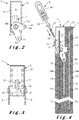
- the references X, Y and Z represented in figure 1B correspond to a geometric coordinate system of the three-dimensional space used to comment on and/or visualize properties of embodiments of the invention.
- the axis 4 of the insert 1 according to this embodiment of the invention is arranged horizontally parallel to the axis X, the tubular connecting piece 31 extends in a direction (generally oblique) perpendicular to axis 4.
- a so-called “vertical” direction refers to a direction parallel to the Z axis represented, which according to this embodiment is preferably a direction parallel to that of the force of gravity.
- the references X, Y and Z are also used to indicate the directions parallel to these axes.
- first and second are used throughout this document exclusively to differentiate between different elements, without implying any order between these elements.
- Insert 1 includes a closed plastic box 2 defining a cavity 22.
- the box 2 comprises a breakable outer wall 21 and intended to be broken with a construction tool, so as to be able to access the cavity 22 from the outside of the box 2.
- the box 2 also comprises two opposite orifices 23.
- the insert 1 comprises a mechanical axis 4 passing through the cavity 22 and the box 2, through the two orifices 23 thereof.
- Axis 4 passes through box 2 in a lower part along axis Z of the latter.
- the insert 1 comprises a yoke 3 comprising a symmetrical plate 34, cut mainly in the shape of a U, a lower part of this plate (corresponding to the hollow of the shape of the U) having an annular shape receiving and being crossed by the axis 4 so as to achieve a pivot connection between the clevis 3 and the pin 4 in the cavity 22.
- the center of the annular shape defines an orifice 33 which is therefore crossed by the pin 4.
- the clevis 3 is provided with a connecting piece 31 arranged symmetrically between and welded to two parallel portions of the yoke plate 34 (corresponding to the branches of the U-shape). The configuration illustrated, the connecting piece 31 is arranged completely in the cavity 22.
- the connecting part can be male or female, and capable of making an arbitrary connection with a mechanical part, the latter preferably being an anchoring device.
- the connecting piece 31 is a female rod of the yoke 3 extending perpendicularly to the axis 4. It therefore comprises a threaded internal part 32, suitable for screwing a rod ( male) threaded, and therefore preferably a threaded rod of an anchoring device.
- the screwing manipulation is particularly simple and quick to perform on site once the box 2 is open, in particular because the connecting piece 31 rotates around the axis 4, and therefore the orientation of the connecting piece 31 can be adjusted to facilitate this manipulation as well as the subsequent use of the anchoring device.
- the direction of extension of the connecting piece 31 forms an angle ⁇ with the vertical direction Z. This angle typically varies from approximately 180° because the rotational movement of the connecting piece 31 around the axis 4 is limited by parts of the box 2 when the wall 21 is removed.
- There is an angular opening for the angle ⁇ around 0° typically, angles which are lower in absolute value than the critical value mentioned below
- the insert 1 also comprises a load take-up support provided with two plates 5 arranged symmetrically on either side of the box 2, against the box 2, similar to ears. These plates 5 extend along planes parallel to each other and parallel to the plane in which the connecting piece 31 is able to move in rotation around the axis 4 (although it can be locked in rotation in a defined position, for example by internal lateral reinforcements of the box 2, during its delivery on site), these planes all being perpendicular to the axis 4.
- the plates 5 are cut to have the specific shape illustrated comprising a top portion 5A (referenced in picture 2 ) annular through which the axis 4 passes at its center (defining a central orifice 53 of the top portion 5A) and blocked at the level of the axis 4 by a fixing of the plate 5 on the box 2, for example, by a clipping of a cylindrical lateral protrusion of the box 2 into a fitting hole 54 of the plate 5.
- Each plate 5 also comprises two feet 5B and 5C (referenced on the figure 2 ) which extend in transverse directions from the top portion 5A, externally to and beyond the cavity 22, such that it is possible to support and/or mechanically couple vertical bars 62 (according to the Z axis) and horizontal 61 (along the X axis) at the end of these feet 5B, 5C without intercepting the box 2 (because the feet move far enough away from the box 2 in said directions), these bars then being able to extend into a construction material constituting a constituent element of a construction provided with the insert 1.
- each of the feet 5B and 5C is pierced with an end hole 52 and 51 respectively able to accommodate such bars 61 and 62.
- one of the bars 61 is an axial metal bar which extends parallel to the axis 4 and which crosses each of the end orifices 52 of the feet 5B of each plate 5, and two other bars 62 are metal bars of gravity essentially folded in their middle into two parallel straight portions so as to give them a U-shape, each of these bars 62 being carried gravitationally by the foot 5B of one of the plates 5 passing through an extremal orifice 51.
- the foot 5B extends in a (main) horizontal direction Y perpendicular to the axis 4 and to said vertical direction Z, and the foot 5C extends transversely to this horizontal direction Y and perpendicular to the axis 4, so as to form an angle comprised between 40 and 90°, preferably between 65 and 85°, more preferably around 75°.
- This configuration makes it possible in particular to arrange the bar 61 parallel to and at the same height, along the Z axis, as the axis 4.
- the bars 61, 62 are directly coupled to the plates 5 and to the axis 4 allowing a optimized transmission of internal forces within a constituent element of the construction comprising the insert 1, and this directly by the insert 1.
- the diagram of the forces involved take points of support close to the axis 4 , and are transmitted to the axis 4.
- the suspension tensile force of the constituent element of the construction is exerted along the direction of extension of the connecting piece 31 when it is connected to a piece of anchoring (therefore obliquely in the plane carried by the Y and Z axes, preferably at an angle ⁇ of approximately 20°) and is compensated (and broken down) along the horizontal Y and vertical Z axes by the internal forces exerted respectively on the bars 61 and 62 close to the axis 4, and transmitted to the latter directly by the plates 5.
- the bars 61 and 62 are preferably metallic with high adhesion to effectively transmit the loads and/or internal forces of a constituent element of a construction provided with the insert 1 at the axis 4 via the load-bearing support.
- the figure 4 illustrates a kit according to one embodiment of the invention.
- This kit comprises an element 7 constituting a construction consisting of a front panel of the construction.
- the latter comprises an inner face 74A and an outer face 74B, and two slices, the upper slice 75 having been referenced.
- This facade panel will be fixed to the construction by means of an anchoring device 8 included in the kit.
- the front panel comprises the insert 1 previously discussed. This has been embedded in a construction material 71, preferably concrete, constituting the front panel, so that the wall 21 extends the inner face 74A, thus being visible to a construction worker.
- the insert 1 is also arranged in height (along the Z axis) in an upper part of the front panel because it is at this location that it is necessary to secure the anchoring device 8 to support and/or fix the facade panel to the construction.
- concrete is poured into the mold and/or formwork, thus forming the reinforced concrete facade panel provided with the insert 1.
- the anchoring device 8 comprises a threaded metal rod 82 so as to be able to easily screw one of its end portions 81 (forming a first end part of the anchoring device 8) into the threaded inner part 32 of the tubular connecting piece 31 .
- the other end portion of this threaded metal rod 82 is fixed to a second end part 83 of the anchoring device 8 which is configured to be suspended and/or attached to a facade of the building.
- a second end part 83 is known to a person skilled in the art, in particular for a mounting system, and preferably consists of a plate.
- the first end part 81 which is in the form of an end portion of a threaded rod differs from the prior art and allows rapid and effective attachment of the anchoring device 8 to the facade panel via the insert 1 Furthermore, given that the bars 61, 62 are directly mechanically coupled to the insert 1, they allow an advantageous transmission of loads and/or internal forces from the facade panel to the construction through the intermediary of the device of anchor 8 and insert 1, as previously described.
- the invention which has been presented relates to an insert 1 for an element 7 constituting a construction comprising a box 2 through which a shaft 4 passes and a connection part 31 mechanically coupled to the shaft 4, capable of rotating around this one.
Landscapes
- Engineering & Computer Science (AREA)
- Architecture (AREA)
- Civil Engineering (AREA)
- Structural Engineering (AREA)
- Chemical & Material Sciences (AREA)
- Ceramic Engineering (AREA)
- Joining Of Building Structures In Genera (AREA)
Claims (15)
- Einsatz (1) für ein Bestandteil (7) eines Bauwerks, umfassend:- eine Achse (4); und- ein Verbindungsstück (31), das mechanisch mit der Achse (4) gekoppelt ist; dadurch gekennzeichnet, dass es weiter ein Gehäuse (2) umfasst, das zumindest teilweise einen Hohlraum (22) begrenzt, und dadurch, dass:- die Achse (4) den Hohlraum (22) und das Gehäuse (2) durch zwei gegenüberliegende Öffnungen (23) desselben durchquert;- das Verbindungsstück (31) Folgendes ist:zumindest teilweise in dem Hohlraum (22) angeordnet,mechanisch mit der Achse (4) in dem Hohlraum (22) gekoppelt, undin der Lage, sich um die Achse (4) zu drehen.
- Einsatz (1) nach dem vorstehenden Anspruch,
dadurch gekennzeichnet, dass er einen Gabelkopf (3) umfasst, umfassend:- einen weiblichen Schaft:• der einen inneren Gewindeabschnitt (32) umfasst,• der sich senkrecht zur Achse (4) erstreckt, und• der aus dem Verbindungsstück (31) besteht; und- eine Öffnung (33), welche die Achse (4) aufnimmt, um eine Schwenkverbindung zwischen dem Gabelkopf (3) und der Achse (4) in dem Hohlraum (22) herzustellen. - Einsatz (1) nach einem der vorstehenden Ansprüche,
dadurch gekennzeichnet, dass er so konfiguriert ist, dass ein Winkel (0) zwischen einer Erstreckungsrichtung des Verbindungsstücks (31) senkrecht zur Achse (4) und einer vertikalen Richtung (Z) senkrecht zur Achse (4) um höchstens 200° variiert, und dass ein Intervall von Werten dieses Winkels (0) existiert, für welches das Verbindungsstück (31) vollständig in dem Hohlraum (22) angeordnet ist. - Einsatz (1) nach einem der vorstehenden Ansprüche, dadurch gekennzeichnet, dass das Gehäuse (2) ein Mittel zum Zugang zum Hohlraum (22) umfasst, bestehend aus mindestens einem aus:- einem abnehmbaren Deckel, der eine Öffnung des Gehäuses (2) abdeckt;- einer zerbrechlichen Außenwand (21).
- Einsatz (1) nach dem vorstehenden Anspruch,
dadurch gekennzeichnet, dass das Mittel zum Zugang zum Hohlraum (22) in der Lage ist, das Gehäuse (2) zu schließen, sodass dieses den Hohlraum (22) vollständig begrenzt, wobei das Verbindungsstück (31) vollständig in dem Hohlraum (22) angeordnet ist, wenn das Gehäuse (2) geschlossen ist. - Einsatz (1) nach einem der vorstehenden Ansprüche,
dadurch gekennzeichnet, dass er weiter einen Lastaufnahmeträger umfasst, der so konfiguriert ist, dass er mindestens eine Metallstange außerhalb des Hohlraums (22) trägt und/oder hält, wobei der Lastaufnahmeträger mindestens eine Platte (5) umfasst, die an dem Gehäuse (2) befestigt ist, worin mindestens eine Öffnung (51, 52) zur Aufnahme einer Metallstange außerhalb des Hohlraums (22) ausgebildet ist. - Einsatz (1) nach dem vorstehenden Anspruch,
dadurch gekennzeichnet, dass das Gehäuse (2) mindestens eine seitliche Ausstülpung umfasst, die sich von einer Außenfläche des Gehäuses (2) nach außen erstreckt, und dass jede Platte (5) eine Einstecköffnung (54) zum Verbinden der Platte (5) gegen das Gehäuse (2) durch Einstecken einer solchen seitlichen Ausstülpung in die Einstecköffnung (54) der Platte (5) umfasst. - Einsatz (1) nach einem der vorstehenden zwei Ansprüche,
dadurch gekennzeichnet, dass sich jede Platte (5) senkrecht zu der Achse (4) erstreckt und umfasst:- einen Scheitelabschnitt (5A), der sich um die Achse (4) herum erstreckt und der eine zentrale Öffnung (53) umfasst, die von der Achse (4) durchquert wird;- zwei Beine (5B, 5C), die sich in Querrichtungen von dem Scheitelabschnitt (5A) über den Hohlraum (22) hinaus erstrecken und die jeweils eine extremale Öffnung (52, 51) zur Aufnahme einer Metallstange (61, 62) umfassen. - Einsatz (1) nach dem vorstehenden Anspruch, wenn er weiter von Anspruch 3 abhängt,
dadurch gekennzeichnet, dass sich eines (5B) der beiden Beine in einer horizontalen Richtung (Y) senkrecht zur Achse (4) und zu der vertikalen Richtung (Z) erstreckt, und dass sich das andere (5C) der beiden Beine quer zu dieser horizontalen Richtung (Y) und senkrecht zur Achse (4) erstreckt. - Einsatz (1) nach einem der Ansprüche 6 bis 9, dadurch gekennzeichnet, dass der Lastaufnahmeträger zwei derartige ähnliche Platten (5) umfasst, die symmetrisch auf beiden Seiten des Hohlraums (22) angeordnet sind.
- Bestandteil (7) eines Bauwerks, das einen Einsatz (1) nach einem der vorstehenden Ansprüche umfasst.
- Bestandteil (7) nach dem vorstehenden Anspruch,dadurch gekennzeichnet, dass:- der Einsatz (1) nach Anspruch 10 ist, wenn er von einem der Ansprüche 8 oder 9 abhängt; und- dass es umfasst:• einen axialen Metallstab (61), der sich parallel zur Achse (4) erstreckt und der die extremalen Öffnungen (52) eines der Beide (5B) jeder Platte (5) durchquert;• zwei Metallschwerkraftstäbe (62), von denen jeder zwei parallele gerade Abschnitte umfasst, die sich senkrecht zur Achse (4) erstrecken, und einen gekrümmten Abschnitt, der die beiden geraden Abschnitte verbindet, um jedem Metallschwerkraftstab (62) eine U-Form zu verleihen,wobei der gekrümmte Abschnitt eines ersten der Metallschwerkraftstäbe (62) die extremale Öffnung (51) des anderen der Beine (5A) einer der Platten (5) durchquert, undwobei der gekrümmte Abschnitt einer zweiten der Metallschwerkraftstäbe (62) die extremale Öffnung (51) des anderen der Beine (5A) der anderen der Platten (5) durchquert.
- Bestandteil (7) nach einem der beiden vorstehenden Ansprüche, dadurch gekennzeichnet, dass es aus einem gegossenen und verfestigten Baumaterial (71) besteht, in das der Einsatz (1) eingebettet ist, sodass ein Rand des Elements (7) das Gehäuse (2) und/oder den Hohlraum (22) umrandet.
- Kit, umfassend:- ein Bestandteil (7) nach einem der Ansprüche 11 bis 13, das aus einer Fassadenplatte des Gebäudes besteht; und- ein Verankerungsstück (8), umfassend:• einen ersten extremalen Teil (81) zum Zusammenwirken mit dem Verbindungsstück (31), um mit letzterem fest verbunden zu werden;• einen zweiten äußeren Teil (83), der konfiguriert ist, um an einer Fassade des Gebäudes aufgehängt und/oder befestigt zu werden.
- Kit nach dem vorstehenden Anspruch,
dadurch gekennzeichnet, dass:- der Einsatz (1) nach Anspruch 2 ist; und dadurch, dass- der erste extremale Teil (81) ein Gewindeschaft ist, der in der Lage ist, in das Verbindungsstück (31) eingeschraubt zu werden.
Applications Claiming Priority (1)
| Application Number | Priority Date | Filing Date | Title |
|---|---|---|---|
| BE20195607A BE1027580B1 (fr) | 2019-09-13 | 2019-09-13 | Insert pour un élément constitutif d’une construction |
Publications (2)
| Publication Number | Publication Date |
|---|---|
| EP3792425A1 EP3792425A1 (de) | 2021-03-17 |
| EP3792425B1 true EP3792425B1 (de) | 2022-08-10 |
Family
ID=68172063
Family Applications (1)
| Application Number | Title | Priority Date | Filing Date |
|---|---|---|---|
| EP20195510.1A Active EP3792425B1 (de) | 2019-09-13 | 2020-09-10 | Einsatz für einen wesentlichen bestandteil eines bauwerks |
Country Status (2)
| Country | Link |
|---|---|
| EP (1) | EP3792425B1 (de) |
| BE (1) | BE1027580B1 (de) |
Family Cites Families (3)
| Publication number | Priority date | Publication date | Assignee | Title |
|---|---|---|---|---|
| AT370471B (de) * | 1980-10-16 | 1983-04-11 | Riss Ges M B H | Vorrichtung zur aufhaengung von fassadenplatten od. dgl. an bauwerken |
| DE3608953A1 (de) * | 1986-03-18 | 1987-09-24 | Deha Baubedarf Kg | Fassadenplattenanker |
| US8966832B1 (en) * | 2014-04-11 | 2015-03-03 | Oscar T. Scott, IV | Mobile aboveground shelter with protected anchoring |
-
2019
- 2019-09-13 BE BE20195607A patent/BE1027580B1/fr active IP Right Grant
-
2020
- 2020-09-10 EP EP20195510.1A patent/EP3792425B1/de active Active
Also Published As
| Publication number | Publication date |
|---|---|
| BE1027580A1 (fr) | 2021-04-07 |
| EP3792425A1 (de) | 2021-03-17 |
| BE1027580B1 (fr) | 2021-04-12 |
Similar Documents
| Publication | Publication Date | Title |
|---|---|---|
| EP3219873A1 (de) | Verteilerkasten zum einbau von kanalisationsrohren, der zur positionierung auf einer armatur geeignet ist | |
| EP3792425B1 (de) | Einsatz für einen wesentlichen bestandteil eines bauwerks | |
| FR2987856A1 (fr) | Attache en deux parties pour le support et la fixation d'une structure de travail en encorbellement a un mur | |
| EP3296481B1 (de) | Vorgefertigtes wand mit integrierter schalung | |
| EP3078784B1 (de) | Mauer mit integrierter schalung mit einem entfernbaren aufnahmemittel eines anschlussmittels an ein fördergerät | |
| EP2594693B1 (de) | Vorrichtung zur Höhenregulierung einer Verschalung für Betonplatten | |
| EP4155483B1 (de) | Hebevorrichtung für vorgefertigte wandplatte | |
| EP1966005B1 (de) | Logistikbox | |
| FR2948139A1 (fr) | Dispositif de raccordement de deux peaux d'un mur a coffrage perdu equipe d'une elingue de manutention. | |
| EP3421336A1 (de) | Befestigungsvorrichtung für traktor, insbesondere vom landwirtschaftlichen typ | |
| FR2586442A1 (fr) | Dispositif de securite de levage et de maintien, notamment pour panneaux de beton arme | |
| EP2634324A1 (de) | Lasche zur Befestigung von Isolierelementen auf eine Stütze | |
| EP3210652B1 (de) | Befestigungshalterung eines tragbaren feuerlöschers | |
| EP0679143B1 (de) | Hebering | |
| FR2980808A1 (fr) | Boitier d'attente monobloc en matiere plastique et dispositif obtenu avec un tel boitier | |
| EP2224566A1 (de) | Gehäuse zum Abwärtsführen von elektrischen Kabeln, das in eine Betonplatte über einer Zwischenwand eingelassen werden kann | |
| EP1382989A1 (de) | Brillenfassung mit flexiblem Faden als Lenshalter | |
| EP1975339A1 (de) | Vorrichtung zur Stabilisierung und zum Umsetzen von Schalungselementen | |
| EP3763897A1 (de) | Hubanker für eine mauer mit integrierter schalung, und mauer mit integrierter schalung, die einen solchen hubanker umfasst | |
| EP4063590A1 (de) | Vorrichtung zum befestigen eines bauzubehörteils an bewehrungen, entsprechendes befestigungsverfahren und bauelement | |
| FR2994994A1 (fr) | Boite de reservation pourvue d'un fond adapte pour supporter des charges statiques ou dynamiques | |
| EP1449785A1 (de) | Befestigungselement für einen Kunststoffdeckel auf einen Kunststoffbehälter zur Vakuumverpackung von Gegenständen in loser Schüttung im Behälter | |
| WO1997010392A1 (fr) | Coffrage perdu pour la realisation de parois porteuses isolantes thermiquement et/ou phonetiquement et parois ainsi obtenues | |
| EP1433501B1 (de) | Vorrichtung zur Befestigung eines Ankerpfostens an einer Tragstruktur | |
| WO2016132195A1 (fr) | Element de construction et procede de montage d'un tel element de construction |
Legal Events
| Date | Code | Title | Description |
|---|---|---|---|
| PUAI | Public reference made under article 153(3) epc to a published international application that has entered the european phase |
Free format text: ORIGINAL CODE: 0009012 |
|
| STAA | Information on the status of an ep patent application or granted ep patent |
Free format text: STATUS: THE APPLICATION HAS BEEN PUBLISHED |
|
| AK | Designated contracting states |
Kind code of ref document: A1 Designated state(s): AL AT BE BG CH CY CZ DE DK EE ES FI FR GB GR HR HU IE IS IT LI LT LU LV MC MK MT NL NO PL PT RO RS SE SI SK SM TR |
|
| AX | Request for extension of the european patent |
Extension state: BA ME |
|
| STAA | Information on the status of an ep patent application or granted ep patent |
Free format text: STATUS: REQUEST FOR EXAMINATION WAS MADE |
|
| 17P | Request for examination filed |
Effective date: 20210907 |
|
| RBV | Designated contracting states (corrected) |
Designated state(s): AL AT BE BG CH CY CZ DE DK EE ES FI FR GB GR HR HU IE IS IT LI LT LU LV MC MK MT NL NO PL PT RO RS SE SI SK SM TR |
|
| GRAP | Despatch of communication of intention to grant a patent |
Free format text: ORIGINAL CODE: EPIDOSNIGR1 |
|
| STAA | Information on the status of an ep patent application or granted ep patent |
Free format text: STATUS: GRANT OF PATENT IS INTENDED |
|
| INTG | Intention to grant announced |
Effective date: 20220419 |
|
| RAP3 | Party data changed (applicant data changed or rights of an application transferred) |
Owner name: FIXINOX SA |
|
| GRAS | Grant fee paid |
Free format text: ORIGINAL CODE: EPIDOSNIGR3 |
|
| GRAA | (expected) grant |
Free format text: ORIGINAL CODE: 0009210 |
|
| STAA | Information on the status of an ep patent application or granted ep patent |
Free format text: STATUS: THE PATENT HAS BEEN GRANTED |
|
| AK | Designated contracting states |
Kind code of ref document: B1 Designated state(s): AL AT BE BG CH CY CZ DE DK EE ES FI FR GB GR HR HU IE IS IT LI LT LU LV MC MK MT NL NO PL PT RO RS SE SI SK SM TR |
|
| REG | Reference to a national code |
Ref country code: AT Ref legal event code: REF Ref document number: 1510648 Country of ref document: AT Kind code of ref document: T Effective date: 20220815 Ref country code: CH Ref legal event code: EP |
|
| REG | Reference to a national code |
Ref country code: IE Ref legal event code: FG4D Free format text: LANGUAGE OF EP DOCUMENT: FRENCH |
|
| REG | Reference to a national code |
Ref country code: DE Ref legal event code: R096 Ref document number: 602020004441 Country of ref document: DE |
|
| REG | Reference to a national code |
Ref country code: NL Ref legal event code: FP |
|
| REG | Reference to a national code |
Ref country code: LT Ref legal event code: MG9D |
|
| PG25 | Lapsed in a contracting state [announced via postgrant information from national office to epo] |
Ref country code: SE Free format text: LAPSE BECAUSE OF FAILURE TO SUBMIT A TRANSLATION OF THE DESCRIPTION OR TO PAY THE FEE WITHIN THE PRESCRIBED TIME-LIMIT Effective date: 20220810 Ref country code: RS Free format text: LAPSE BECAUSE OF FAILURE TO SUBMIT A TRANSLATION OF THE DESCRIPTION OR TO PAY THE FEE WITHIN THE PRESCRIBED TIME-LIMIT Effective date: 20220810 Ref country code: PT Free format text: LAPSE BECAUSE OF FAILURE TO SUBMIT A TRANSLATION OF THE DESCRIPTION OR TO PAY THE FEE WITHIN THE PRESCRIBED TIME-LIMIT Effective date: 20221212 Ref country code: NO Free format text: LAPSE BECAUSE OF FAILURE TO SUBMIT A TRANSLATION OF THE DESCRIPTION OR TO PAY THE FEE WITHIN THE PRESCRIBED TIME-LIMIT Effective date: 20221110 Ref country code: LV Free format text: LAPSE BECAUSE OF FAILURE TO SUBMIT A TRANSLATION OF THE DESCRIPTION OR TO PAY THE FEE WITHIN THE PRESCRIBED TIME-LIMIT Effective date: 20220810 Ref country code: LT Free format text: LAPSE BECAUSE OF FAILURE TO SUBMIT A TRANSLATION OF THE DESCRIPTION OR TO PAY THE FEE WITHIN THE PRESCRIBED TIME-LIMIT Effective date: 20220810 Ref country code: FI Free format text: LAPSE BECAUSE OF FAILURE TO SUBMIT A TRANSLATION OF THE DESCRIPTION OR TO PAY THE FEE WITHIN THE PRESCRIBED TIME-LIMIT Effective date: 20220810 |
|
| REG | Reference to a national code |
Ref country code: AT Ref legal event code: MK05 Ref document number: 1510648 Country of ref document: AT Kind code of ref document: T Effective date: 20220810 |
|
| PG25 | Lapsed in a contracting state [announced via postgrant information from national office to epo] |
Ref country code: PL Free format text: LAPSE BECAUSE OF FAILURE TO SUBMIT A TRANSLATION OF THE DESCRIPTION OR TO PAY THE FEE WITHIN THE PRESCRIBED TIME-LIMIT Effective date: 20220810 Ref country code: IS Free format text: LAPSE BECAUSE OF FAILURE TO SUBMIT A TRANSLATION OF THE DESCRIPTION OR TO PAY THE FEE WITHIN THE PRESCRIBED TIME-LIMIT Effective date: 20221210 Ref country code: HR Free format text: LAPSE BECAUSE OF FAILURE TO SUBMIT A TRANSLATION OF THE DESCRIPTION OR TO PAY THE FEE WITHIN THE PRESCRIBED TIME-LIMIT Effective date: 20220810 Ref country code: GR Free format text: LAPSE BECAUSE OF FAILURE TO SUBMIT A TRANSLATION OF THE DESCRIPTION OR TO PAY THE FEE WITHIN THE PRESCRIBED TIME-LIMIT Effective date: 20221111 |
|
| PG25 | Lapsed in a contracting state [announced via postgrant information from national office to epo] |
Ref country code: SM Free format text: LAPSE BECAUSE OF FAILURE TO SUBMIT A TRANSLATION OF THE DESCRIPTION OR TO PAY THE FEE WITHIN THE PRESCRIBED TIME-LIMIT Effective date: 20220810 Ref country code: RO Free format text: LAPSE BECAUSE OF FAILURE TO SUBMIT A TRANSLATION OF THE DESCRIPTION OR TO PAY THE FEE WITHIN THE PRESCRIBED TIME-LIMIT Effective date: 20220810 Ref country code: ES Free format text: LAPSE BECAUSE OF FAILURE TO SUBMIT A TRANSLATION OF THE DESCRIPTION OR TO PAY THE FEE WITHIN THE PRESCRIBED TIME-LIMIT Effective date: 20220810 Ref country code: DK Free format text: LAPSE BECAUSE OF FAILURE TO SUBMIT A TRANSLATION OF THE DESCRIPTION OR TO PAY THE FEE WITHIN THE PRESCRIBED TIME-LIMIT Effective date: 20220810 Ref country code: CZ Free format text: LAPSE BECAUSE OF FAILURE TO SUBMIT A TRANSLATION OF THE DESCRIPTION OR TO PAY THE FEE WITHIN THE PRESCRIBED TIME-LIMIT Effective date: 20220810 Ref country code: AT Free format text: LAPSE BECAUSE OF FAILURE TO SUBMIT A TRANSLATION OF THE DESCRIPTION OR TO PAY THE FEE WITHIN THE PRESCRIBED TIME-LIMIT Effective date: 20220810 |
|
| REG | Reference to a national code |
Ref country code: DE Ref legal event code: R097 Ref document number: 602020004441 Country of ref document: DE |
|
| PG25 | Lapsed in a contracting state [announced via postgrant information from national office to epo] |
Ref country code: SK Free format text: LAPSE BECAUSE OF FAILURE TO SUBMIT A TRANSLATION OF THE DESCRIPTION OR TO PAY THE FEE WITHIN THE PRESCRIBED TIME-LIMIT Effective date: 20220810 Ref country code: MC Free format text: LAPSE BECAUSE OF FAILURE TO SUBMIT A TRANSLATION OF THE DESCRIPTION OR TO PAY THE FEE WITHIN THE PRESCRIBED TIME-LIMIT Effective date: 20220810 Ref country code: EE Free format text: LAPSE BECAUSE OF FAILURE TO SUBMIT A TRANSLATION OF THE DESCRIPTION OR TO PAY THE FEE WITHIN THE PRESCRIBED TIME-LIMIT Effective date: 20220810 |
|
| PLBE | No opposition filed within time limit |
Free format text: ORIGINAL CODE: 0009261 |
|
| STAA | Information on the status of an ep patent application or granted ep patent |
Free format text: STATUS: NO OPPOSITION FILED WITHIN TIME LIMIT |
|
| PG25 | Lapsed in a contracting state [announced via postgrant information from national office to epo] |
Ref country code: AL Free format text: LAPSE BECAUSE OF FAILURE TO SUBMIT A TRANSLATION OF THE DESCRIPTION OR TO PAY THE FEE WITHIN THE PRESCRIBED TIME-LIMIT Effective date: 20220810 |
|
| 26N | No opposition filed |
Effective date: 20230511 |
|
| PG25 | Lapsed in a contracting state [announced via postgrant information from national office to epo] |
Ref country code: IE Free format text: LAPSE BECAUSE OF NON-PAYMENT OF DUE FEES Effective date: 20220910 |
|
| PG25 | Lapsed in a contracting state [announced via postgrant information from national office to epo] |
Ref country code: SI Free format text: LAPSE BECAUSE OF FAILURE TO SUBMIT A TRANSLATION OF THE DESCRIPTION OR TO PAY THE FEE WITHIN THE PRESCRIBED TIME-LIMIT Effective date: 20220810 |
|
| PGFP | Annual fee paid to national office [announced via postgrant information from national office to epo] |
Ref country code: LU Payment date: 20230926 Year of fee payment: 4 |
|
| PG25 | Lapsed in a contracting state [announced via postgrant information from national office to epo] |
Ref country code: CY Free format text: LAPSE BECAUSE OF FAILURE TO SUBMIT A TRANSLATION OF THE DESCRIPTION OR TO PAY THE FEE WITHIN THE PRESCRIBED TIME-LIMIT Effective date: 20220810 |
|
| REG | Reference to a national code |
Ref country code: CH Ref legal event code: PL |
|
| PG25 | Lapsed in a contracting state [announced via postgrant information from national office to epo] |
Ref country code: MK Free format text: LAPSE BECAUSE OF FAILURE TO SUBMIT A TRANSLATION OF THE DESCRIPTION OR TO PAY THE FEE WITHIN THE PRESCRIBED TIME-LIMIT Effective date: 20220810 Ref country code: IT Free format text: LAPSE BECAUSE OF FAILURE TO SUBMIT A TRANSLATION OF THE DESCRIPTION OR TO PAY THE FEE WITHIN THE PRESCRIBED TIME-LIMIT Effective date: 20220810 Ref country code: HU Free format text: LAPSE BECAUSE OF FAILURE TO SUBMIT A TRANSLATION OF THE DESCRIPTION OR TO PAY THE FEE WITHIN THE PRESCRIBED TIME-LIMIT; INVALID AB INITIO Effective date: 20200910 |
|
| PG25 | Lapsed in a contracting state [announced via postgrant information from national office to epo] |
Ref country code: CH Free format text: LAPSE BECAUSE OF NON-PAYMENT OF DUE FEES Effective date: 20230930 |
|
| PG25 | Lapsed in a contracting state [announced via postgrant information from national office to epo] |
Ref country code: CH Free format text: LAPSE BECAUSE OF NON-PAYMENT OF DUE FEES Effective date: 20230930 Ref country code: BG Free format text: LAPSE BECAUSE OF FAILURE TO SUBMIT A TRANSLATION OF THE DESCRIPTION OR TO PAY THE FEE WITHIN THE PRESCRIBED TIME-LIMIT Effective date: 20220810 |
|
| PG25 | Lapsed in a contracting state [announced via postgrant information from national office to epo] |
Ref country code: MT Free format text: LAPSE BECAUSE OF FAILURE TO SUBMIT A TRANSLATION OF THE DESCRIPTION OR TO PAY THE FEE WITHIN THE PRESCRIBED TIME-LIMIT Effective date: 20220810 |
|
| PG25 | Lapsed in a contracting state [announced via postgrant information from national office to epo] |
Ref country code: LU Free format text: LAPSE BECAUSE OF NON-PAYMENT OF DUE FEES Effective date: 20240910 |
|
| GBPC | Gb: european patent ceased through non-payment of renewal fee |
Effective date: 20240910 |
|
| PG25 | Lapsed in a contracting state [announced via postgrant information from national office to epo] |
Ref country code: GB Free format text: LAPSE BECAUSE OF NON-PAYMENT OF DUE FEES Effective date: 20240910 |
|
| PGFP | Annual fee paid to national office [announced via postgrant information from national office to epo] |
Ref country code: DE Payment date: 20250926 Year of fee payment: 6 |
|
| PGFP | Annual fee paid to national office [announced via postgrant information from national office to epo] |
Ref country code: NL Payment date: 20250923 Year of fee payment: 6 |
|
| PGFP | Annual fee paid to national office [announced via postgrant information from national office to epo] |
Ref country code: BE Payment date: 20250923 Year of fee payment: 6 |
|
| PGFP | Annual fee paid to national office [announced via postgrant information from national office to epo] |
Ref country code: FR Payment date: 20250923 Year of fee payment: 6 |
|
| PG25 | Lapsed in a contracting state [announced via postgrant information from national office to epo] |
Ref country code: TR Free format text: LAPSE BECAUSE OF FAILURE TO SUBMIT A TRANSLATION OF THE DESCRIPTION OR TO PAY THE FEE WITHIN THE PRESCRIBED TIME-LIMIT Effective date: 20220810 |