EP3792467B1 - Installation pour le stockage de gaz comprimé - Google Patents
Installation pour le stockage de gaz comprimé Download PDFInfo
- Publication number
- EP3792467B1 EP3792467B1 EP20000302.8A EP20000302A EP3792467B1 EP 3792467 B1 EP3792467 B1 EP 3792467B1 EP 20000302 A EP20000302 A EP 20000302A EP 3792467 B1 EP3792467 B1 EP 3792467B1
- Authority
- EP
- European Patent Office
- Prior art keywords
- compressed air
- air
- tank
- underground
- energy storage
- Prior art date
- Legal status (The legal status is an assumption and is not a legal conclusion. Google has not performed a legal analysis and makes no representation as to the accuracy of the status listed.)
- Active
Links
Images
Classifications
-
- F—MECHANICAL ENGINEERING; LIGHTING; HEATING; WEAPONS; BLASTING
- F02—COMBUSTION ENGINES; HOT-GAS OR COMBUSTION-PRODUCT ENGINE PLANTS
- F02C—GAS-TURBINE PLANTS; AIR INTAKES FOR JET-PROPULSION PLANTS; CONTROLLING FUEL SUPPLY IN AIR-BREATHING JET-PROPULSION PLANTS
- F02C6/00—Plural gas-turbine plants; Combinations of gas-turbine plants with other apparatus; Adaptations of gas-turbine plants for special use
- F02C6/14—Gas-turbine plants having means for storing energy, e.g. for meeting peak loads
- F02C6/16—Gas-turbine plants having means for storing energy, e.g. for meeting peak loads for storing compressed air
-
- E—FIXED CONSTRUCTIONS
- E04—BUILDING
- E04H—BUILDINGS OR LIKE STRUCTURES FOR PARTICULAR PURPOSES; SWIMMING OR SPLASH BATHS OR POOLS; MASTS; FENCING; TENTS OR CANOPIES, IN GENERAL
- E04H7/00—Construction or assembling of bulk storage containers employing civil engineering techniques in situ or off the site
- E04H7/02—Containers for fluids or gases; Supports therefor
-
- F—MECHANICAL ENGINEERING; LIGHTING; HEATING; WEAPONS; BLASTING
- F17—STORING OR DISTRIBUTING GASES OR LIQUIDS
- F17C—VESSELS FOR CONTAINING OR STORING COMPRESSED, LIQUEFIED OR SOLIDIFIED GASES; FIXED-CAPACITY GAS-HOLDERS; FILLING VESSELS WITH, OR DISCHARGING FROM VESSELS, COMPRESSED, LIQUEFIED, OR SOLIDIFIED GASES
- F17C1/00—Pressure vessels, e.g. gas cylinder, gas tank, replaceable cartridge
- F17C1/007—Underground or underwater storage
-
- F—MECHANICAL ENGINEERING; LIGHTING; HEATING; WEAPONS; BLASTING
- F17—STORING OR DISTRIBUTING GASES OR LIQUIDS
- F17C—VESSELS FOR CONTAINING OR STORING COMPRESSED, LIQUEFIED OR SOLIDIFIED GASES; FIXED-CAPACITY GAS-HOLDERS; FILLING VESSELS WITH, OR DISCHARGING FROM VESSELS, COMPRESSED, LIQUEFIED, OR SOLIDIFIED GASES
- F17C2201/00—Vessel construction, in particular geometry, arrangement or size
- F17C2201/01—Shape
- F17C2201/0104—Shape cylindrical
- F17C2201/0119—Shape cylindrical with flat end-piece
-
- F—MECHANICAL ENGINEERING; LIGHTING; HEATING; WEAPONS; BLASTING
- F17—STORING OR DISTRIBUTING GASES OR LIQUIDS
- F17C—VESSELS FOR CONTAINING OR STORING COMPRESSED, LIQUEFIED OR SOLIDIFIED GASES; FIXED-CAPACITY GAS-HOLDERS; FILLING VESSELS WITH, OR DISCHARGING FROM VESSELS, COMPRESSED, LIQUEFIED, OR SOLIDIFIED GASES
- F17C2201/00—Vessel construction, in particular geometry, arrangement or size
- F17C2201/03—Orientation
- F17C2201/032—Orientation with substantially vertical main axis
-
- F—MECHANICAL ENGINEERING; LIGHTING; HEATING; WEAPONS; BLASTING
- F17—STORING OR DISTRIBUTING GASES OR LIQUIDS
- F17C—VESSELS FOR CONTAINING OR STORING COMPRESSED, LIQUEFIED OR SOLIDIFIED GASES; FIXED-CAPACITY GAS-HOLDERS; FILLING VESSELS WITH, OR DISCHARGING FROM VESSELS, COMPRESSED, LIQUEFIED, OR SOLIDIFIED GASES
- F17C2201/00—Vessel construction, in particular geometry, arrangement or size
- F17C2201/05—Size
- F17C2201/054—Size medium (>1 m3)
-
- F—MECHANICAL ENGINEERING; LIGHTING; HEATING; WEAPONS; BLASTING
- F17—STORING OR DISTRIBUTING GASES OR LIQUIDS
- F17C—VESSELS FOR CONTAINING OR STORING COMPRESSED, LIQUEFIED OR SOLIDIFIED GASES; FIXED-CAPACITY GAS-HOLDERS; FILLING VESSELS WITH, OR DISCHARGING FROM VESSELS, COMPRESSED, LIQUEFIED, OR SOLIDIFIED GASES
- F17C2203/00—Vessel construction, in particular walls or details thereof
- F17C2203/01—Reinforcing or suspension means
- F17C2203/011—Reinforcing means
- F17C2203/012—Reinforcing means on or in the wall, e.g. ribs
-
- F—MECHANICAL ENGINEERING; LIGHTING; HEATING; WEAPONS; BLASTING
- F17—STORING OR DISTRIBUTING GASES OR LIQUIDS
- F17C—VESSELS FOR CONTAINING OR STORING COMPRESSED, LIQUEFIED OR SOLIDIFIED GASES; FIXED-CAPACITY GAS-HOLDERS; FILLING VESSELS WITH, OR DISCHARGING FROM VESSELS, COMPRESSED, LIQUEFIED, OR SOLIDIFIED GASES
- F17C2203/00—Vessel construction, in particular walls or details thereof
- F17C2203/03—Thermal insulations
- F17C2203/0304—Thermal insulations by solid means
- F17C2203/0345—Fibres
-
- F—MECHANICAL ENGINEERING; LIGHTING; HEATING; WEAPONS; BLASTING
- F17—STORING OR DISTRIBUTING GASES OR LIQUIDS
- F17C—VESSELS FOR CONTAINING OR STORING COMPRESSED, LIQUEFIED OR SOLIDIFIED GASES; FIXED-CAPACITY GAS-HOLDERS; FILLING VESSELS WITH, OR DISCHARGING FROM VESSELS, COMPRESSED, LIQUEFIED, OR SOLIDIFIED GASES
- F17C2203/00—Vessel construction, in particular walls or details thereof
- F17C2203/03—Thermal insulations
- F17C2203/0304—Thermal insulations by solid means
- F17C2203/0345—Fibres
- F17C2203/035—Glass wool
-
- F—MECHANICAL ENGINEERING; LIGHTING; HEATING; WEAPONS; BLASTING
- F17—STORING OR DISTRIBUTING GASES OR LIQUIDS
- F17C—VESSELS FOR CONTAINING OR STORING COMPRESSED, LIQUEFIED OR SOLIDIFIED GASES; FIXED-CAPACITY GAS-HOLDERS; FILLING VESSELS WITH, OR DISCHARGING FROM VESSELS, COMPRESSED, LIQUEFIED, OR SOLIDIFIED GASES
- F17C2203/00—Vessel construction, in particular walls or details thereof
- F17C2203/06—Materials for walls or layers thereof; Properties or structures of walls or their materials
- F17C2203/0602—Wall structures; Special features thereof
- F17C2203/0604—Liners
-
- F—MECHANICAL ENGINEERING; LIGHTING; HEATING; WEAPONS; BLASTING
- F17—STORING OR DISTRIBUTING GASES OR LIQUIDS
- F17C—VESSELS FOR CONTAINING OR STORING COMPRESSED, LIQUEFIED OR SOLIDIFIED GASES; FIXED-CAPACITY GAS-HOLDERS; FILLING VESSELS WITH, OR DISCHARGING FROM VESSELS, COMPRESSED, LIQUEFIED, OR SOLIDIFIED GASES
- F17C2203/00—Vessel construction, in particular walls or details thereof
- F17C2203/06—Materials for walls or layers thereof; Properties or structures of walls or their materials
- F17C2203/0634—Materials for walls or layers thereof
- F17C2203/0678—Concrete
-
- F—MECHANICAL ENGINEERING; LIGHTING; HEATING; WEAPONS; BLASTING
- F17—STORING OR DISTRIBUTING GASES OR LIQUIDS
- F17C—VESSELS FOR CONTAINING OR STORING COMPRESSED, LIQUEFIED OR SOLIDIFIED GASES; FIXED-CAPACITY GAS-HOLDERS; FILLING VESSELS WITH, OR DISCHARGING FROM VESSELS, COMPRESSED, LIQUEFIED, OR SOLIDIFIED GASES
- F17C2203/00—Vessel construction, in particular walls or details thereof
- F17C2203/06—Materials for walls or layers thereof; Properties or structures of walls or their materials
- F17C2203/068—Special properties of materials for vessel walls
- F17C2203/0685—Special properties of materials for vessel walls flexible
-
- F—MECHANICAL ENGINEERING; LIGHTING; HEATING; WEAPONS; BLASTING
- F17—STORING OR DISTRIBUTING GASES OR LIQUIDS
- F17C—VESSELS FOR CONTAINING OR STORING COMPRESSED, LIQUEFIED OR SOLIDIFIED GASES; FIXED-CAPACITY GAS-HOLDERS; FILLING VESSELS WITH, OR DISCHARGING FROM VESSELS, COMPRESSED, LIQUEFIED, OR SOLIDIFIED GASES
- F17C2205/00—Vessel construction, in particular mounting arrangements, attachments or identifications means
- F17C2205/03—Fluid connections, filters, valves, closure means or other attachments
- F17C2205/0302—Fittings, valves, filters, or components in connection with the gas storage device
- F17C2205/0323—Valves
-
- F—MECHANICAL ENGINEERING; LIGHTING; HEATING; WEAPONS; BLASTING
- F17—STORING OR DISTRIBUTING GASES OR LIQUIDS
- F17C—VESSELS FOR CONTAINING OR STORING COMPRESSED, LIQUEFIED OR SOLIDIFIED GASES; FIXED-CAPACITY GAS-HOLDERS; FILLING VESSELS WITH, OR DISCHARGING FROM VESSELS, COMPRESSED, LIQUEFIED, OR SOLIDIFIED GASES
- F17C2205/00—Vessel construction, in particular mounting arrangements, attachments or identifications means
- F17C2205/03—Fluid connections, filters, valves, closure means or other attachments
- F17C2205/0302—Fittings, valves, filters, or components in connection with the gas storage device
- F17C2205/0379—Manholes or access openings for human beings
-
- F—MECHANICAL ENGINEERING; LIGHTING; HEATING; WEAPONS; BLASTING
- F17—STORING OR DISTRIBUTING GASES OR LIQUIDS
- F17C—VESSELS FOR CONTAINING OR STORING COMPRESSED, LIQUEFIED OR SOLIDIFIED GASES; FIXED-CAPACITY GAS-HOLDERS; FILLING VESSELS WITH, OR DISCHARGING FROM VESSELS, COMPRESSED, LIQUEFIED, OR SOLIDIFIED GASES
- F17C2205/00—Vessel construction, in particular mounting arrangements, attachments or identifications means
- F17C2205/03—Fluid connections, filters, valves, closure means or other attachments
- F17C2205/0388—Arrangement of valves, regulators, filters
- F17C2205/0394—Arrangement of valves, regulators, filters in direct contact with the pressure vessel
-
- F—MECHANICAL ENGINEERING; LIGHTING; HEATING; WEAPONS; BLASTING
- F17—STORING OR DISTRIBUTING GASES OR LIQUIDS
- F17C—VESSELS FOR CONTAINING OR STORING COMPRESSED, LIQUEFIED OR SOLIDIFIED GASES; FIXED-CAPACITY GAS-HOLDERS; FILLING VESSELS WITH, OR DISCHARGING FROM VESSELS, COMPRESSED, LIQUEFIED, OR SOLIDIFIED GASES
- F17C2221/00—Handled fluid, in particular type of fluid
- F17C2221/03—Mixtures
- F17C2221/031—Air
-
- F—MECHANICAL ENGINEERING; LIGHTING; HEATING; WEAPONS; BLASTING
- F17—STORING OR DISTRIBUTING GASES OR LIQUIDS
- F17C—VESSELS FOR CONTAINING OR STORING COMPRESSED, LIQUEFIED OR SOLIDIFIED GASES; FIXED-CAPACITY GAS-HOLDERS; FILLING VESSELS WITH, OR DISCHARGING FROM VESSELS, COMPRESSED, LIQUEFIED, OR SOLIDIFIED GASES
- F17C2223/00—Handled fluid before transfer, i.e. state of fluid when stored in the vessel or before transfer from the vessel
- F17C2223/01—Handled fluid before transfer, i.e. state of fluid when stored in the vessel or before transfer from the vessel characterised by the phase
- F17C2223/0107—Single phase
- F17C2223/0123—Single phase gaseous, e.g. CNG, GNC
-
- F—MECHANICAL ENGINEERING; LIGHTING; HEATING; WEAPONS; BLASTING
- F17—STORING OR DISTRIBUTING GASES OR LIQUIDS
- F17C—VESSELS FOR CONTAINING OR STORING COMPRESSED, LIQUEFIED OR SOLIDIFIED GASES; FIXED-CAPACITY GAS-HOLDERS; FILLING VESSELS WITH, OR DISCHARGING FROM VESSELS, COMPRESSED, LIQUEFIED, OR SOLIDIFIED GASES
- F17C2223/00—Handled fluid before transfer, i.e. state of fluid when stored in the vessel or before transfer from the vessel
- F17C2223/03—Handled fluid before transfer, i.e. state of fluid when stored in the vessel or before transfer from the vessel characterised by the pressure level
- F17C2223/036—Very high pressure (>80 bar)
-
- F—MECHANICAL ENGINEERING; LIGHTING; HEATING; WEAPONS; BLASTING
- F17—STORING OR DISTRIBUTING GASES OR LIQUIDS
- F17C—VESSELS FOR CONTAINING OR STORING COMPRESSED, LIQUEFIED OR SOLIDIFIED GASES; FIXED-CAPACITY GAS-HOLDERS; FILLING VESSELS WITH, OR DISCHARGING FROM VESSELS, COMPRESSED, LIQUEFIED, OR SOLIDIFIED GASES
- F17C2260/00—Purposes of gas storage and gas handling
- F17C2260/02—Improving properties related to fluid or fluid transfer
- F17C2260/023—Avoiding overheating
-
- F—MECHANICAL ENGINEERING; LIGHTING; HEATING; WEAPONS; BLASTING
- F17—STORING OR DISTRIBUTING GASES OR LIQUIDS
- F17C—VESSELS FOR CONTAINING OR STORING COMPRESSED, LIQUEFIED OR SOLIDIFIED GASES; FIXED-CAPACITY GAS-HOLDERS; FILLING VESSELS WITH, OR DISCHARGING FROM VESSELS, COMPRESSED, LIQUEFIED, OR SOLIDIFIED GASES
- F17C2270/00—Applications
- F17C2270/01—Applications for fluid transport or storage
- F17C2270/0142—Applications for fluid transport or storage placed underground
- F17C2270/0144—Type of cavity
- F17C2270/0147—Type of cavity by burying vessels
-
- F—MECHANICAL ENGINEERING; LIGHTING; HEATING; WEAPONS; BLASTING
- F17—STORING OR DISTRIBUTING GASES OR LIQUIDS
- F17C—VESSELS FOR CONTAINING OR STORING COMPRESSED, LIQUEFIED OR SOLIDIFIED GASES; FIXED-CAPACITY GAS-HOLDERS; FILLING VESSELS WITH, OR DISCHARGING FROM VESSELS, COMPRESSED, LIQUEFIED, OR SOLIDIFIED GASES
- F17C2270/00—Applications
- F17C2270/01—Applications for fluid transport or storage
- F17C2270/0142—Applications for fluid transport or storage placed underground
- F17C2270/0144—Type of cavity
- F17C2270/0149—Type of cavity by digging cavities
-
- F—MECHANICAL ENGINEERING; LIGHTING; HEATING; WEAPONS; BLASTING
- F17—STORING OR DISTRIBUTING GASES OR LIQUIDS
- F17C—VESSELS FOR CONTAINING OR STORING COMPRESSED, LIQUEFIED OR SOLIDIFIED GASES; FIXED-CAPACITY GAS-HOLDERS; FILLING VESSELS WITH, OR DISCHARGING FROM VESSELS, COMPRESSED, LIQUEFIED, OR SOLIDIFIED GASES
- F17C2270/00—Applications
- F17C2270/01—Applications for fluid transport or storage
- F17C2270/0142—Applications for fluid transport or storage placed underground
- F17C2270/0144—Type of cavity
- F17C2270/0155—Type of cavity by using natural cavities
-
- Y—GENERAL TAGGING OF NEW TECHNOLOGICAL DEVELOPMENTS; GENERAL TAGGING OF CROSS-SECTIONAL TECHNOLOGIES SPANNING OVER SEVERAL SECTIONS OF THE IPC; TECHNICAL SUBJECTS COVERED BY FORMER USPC CROSS-REFERENCE ART COLLECTIONS [XRACs] AND DIGESTS
- Y02—TECHNOLOGIES OR APPLICATIONS FOR MITIGATION OR ADAPTATION AGAINST CLIMATE CHANGE
- Y02E—REDUCTION OF GREENHOUSE GAS [GHG] EMISSIONS, RELATED TO ENERGY GENERATION, TRANSMISSION OR DISTRIBUTION
- Y02E60/00—Enabling technologies; Technologies with a potential or indirect contribution to GHG emissions mitigation
- Y02E60/16—Mechanical energy storage, e.g. flywheels or pressurised fluids
Definitions
- the subject of the invention is an underground compressed air storage, built-in particularly in the post-mining mine shaft, intended particularly for air and thermal energy storage from compressed air cooling as part of adiabatic energy storage systems in compressed air (ACAES, Adiabatic Compressed Air Energy Storage).
- ACAES Adiabatic Compressed Air Energy Storage
- Compressed air storage is an indispensable element of the compressed air storage systems (CAES) structure. Except for the air storage itself in CAES systems it is necessary to use an air compressor unit (compressor and electric motor), where the process of compressing atmospheric air is carried out by using electricity directed to the storage system. Another indispensable element is the air expander unit (expander and electricity generator), which enables the conversion of potential energy of previously stored air into electricity.
- the work of the compressor unit is carried out at the stage of charging the CAES system, where this process takes place during periods of overproduction of energy in generating systems, while the expander works at the stage of CAES system discharging, i.e. in a situation where there is an increased demand for energy in the power system.
- Compressed air energy storage is a concept proposed for system applications and as such is a competition for the most commonly used pumped storage power plants.
- the large scale of projects implemented in the world requires, in general, planning of compressed air reservoirs as underground structures.
- salt caverns are used - natural or resulting from the leaching of the salt deposit.
- the use of salt caverns as potential storage of compressed air in many countries, including Poland is currently practically impossible due to the strategic need to increase the storage capacity of hydrocarbons: crude oil and natural gas.
- intersection air cooling is implemented to reduce the unit work of the compression process and to ensure a safe compressed air temperature from the point of view of safe operation of the compressor.
- the cooling of the air leaving the compressor i.e. before it enters the storage tank (above ground or underground), is determined by the thermal resistance of the materials used in the construction of the tanks and reduction of heat loss to the environment.
- the purpose of air cooling processes is its storage at generally low temperature. Due to the low potential of such air to perform work in the expander, at the stage of CAES system discharge, air-heating is conducted.
- the thermal energy storage system in the ACAES system is designed to store the heat captured from the compressed air, until the beginning of the discharge stage, in which the compressed air leaving the air storage is directed to the expander driving the electricity generator.
- the air is subjected to a heating process prior to entering the expander by using the heat stored during the charging phase of the electricity storage system.
- Several solutions for storing high-temperature heat from the cooling of compressed air are known.
- the temperature of the air leaving a given section of the compressor can reach as high as over 600 °C.
- the heat collection and storage system should allow the compressed air to be cooled to a level that guarantees the operational safety of the compressed air storage but at the same time it should allow heat storage at a high level of storage temperature, which will allow for a high degree of heating of the air directed to the expander at the stage of ACAES system discharge.
- solid storage materials in thermal energy storage system, these can be ceramic elements, concrete or natural rocks.
- An example of the use of ceramic materials is the heat accumulator used as part of the world's most advanced adiabatic ADELE demonstration system, to be located in Germany.
- Planed thermal energy storage system is a ground structure, where a cylindrical concrete tank is filled with ceramic bricks, enabling thermal energy storage at a temperature of 600 °C.
- the disadvantage of this solution is the need to use a concrete tank with very thick, reinforced walls in the storage tank construction, which is a consequence of a high stresses exerted on the walls due to the differences between the atmospheric air pressure and the stored compressed air pressure giving away or receiving heat from the ceramic material.
- the disadvantage of the concept developed by ALACAES if coal mine gate roads are used is related to the difficulties in the construction of pipelines for hot air transport between the above-ground engine room (compressor set and expander set) and an underground storage with thermal energy storage, or possible difficulties in constructing the engine room as an underground installation in close proximity to the air storage integrated with the thermal energy storage system.
- solid materials for thermal energy storage another possible solution is to use liquid thermal oil for this purpose.
- the air is diaphragm cooled by oil directed to the exchangers from the cold oil tank. After receiving the heat, the heated oil is directed to a thermally insulated hot oil tank and stored there until the ACAES system discharge stage begins.
- thermal oil is then directed to the diaphragm heat exchanger, where it gives off heat to the air directed from the compressed air storage to the expander.
- the disadvantages of using the thermal oil system is the need for diaphragm heat exchangers and safety considerations related to the use of high temperature oil.
- thermal oils generally do not allow heating to temperatures above 400 °C.
- the disadvantage of using thermal oils is their relatively low heat capacity, which in terms of weight, is about twice lower than that of water.
- Document US4147204A discloses a compressed air energy storage system according to the state of the art.
- the purpose of the invention is to store high-pressure, high temperature air entering the tank as part of adiabatic energy storage systems in compressed air while maintaining safety considerations for the materials used and minimizing heat losses to the storage environment.
- the goal was achieved through the use of cylindrical, airtight underground tank with a vertical axis, which may, in particular be an abandoned mine shaft, in which a thermal energy storage systemwas built, constituting a structure made of cylindrical elements with thermal insulation, built in series, in the axis of the underground tank and filled with heat accumulating bed .
- the invention as defined in claim 1 consists of an underground compressed air storage system, built-up especially in an abandoned mine shaft, constituting a vertical, cylindrical underground tank, preferably a mine shaft, characterized by the fact that the system contains a pressure tank with a lining and a bottom, tightly closed from above with a lid with a built-in supply port with a shut-off valve through which high temperature air is supplied and shut-off valve through which a high temperature air is discharged and where cylindrical elements are suspended coaxially in vertical position on the upright supports, closed from the top with a lid, from the bottom with endplate with pressure flaps and externally covered with thermal insulation made of glass or ceramic fibers and filled inside with a heat accumulative insert
- the preferred storage solution according to the invention is characterized in that it has a revision hatch in the lid.
- An advantageous storage solution according to the invention is characterized in that rock or ceramic elements supported on the perforated supporting plates are used as the accumulation bed, enabling heating to high temperatures.
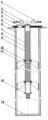
- the subject of the invention in the example implementation is explained in more detail on the drawing, showing a cross-section through an adapted cylindrical mine shaft in the plane defined by its axis.
- the drawing shows the compressed air storage, where a vertical, cylindrical underground tank is used, whose lining 6, bottom 13 and lid 5 form a sealed pressure tank.
- the tank lid is sealed with a thermal energy storage system lid 3, which is an integral element of the compressed air tank.
- the thermal energy storage system consists of cylindrical elements 7, externally covered with thermal insulation of glass or ceramic fibers 8 and inside filled with a heat accumulating insert 9, constituting rock elements, mounted on perforated supporting plates 10.
- Cylindrical elements 7 of the reservoir and perforated supporting plates 10 are built in the axis of the tank underground.
- the perforated supporting plates 10 are located between the flanges of individual cylindrical elements of the thermal energy storage system.
- the thermal energy storage system is suspended in the space of the underground tank on the upright supports 11.
- Hot, compressed air is introduced into the tank through an inlet pipeline with a built-in shut-off valve 2 and flows axially through the thermal energy storage system, giving heat to the rock accumulating material.
- the last element of the thermal energy storage system through which air flows at the tank charging stage is the endplate with pressure flaps 12.
- the geometry of the cylindrical elements 7 and the amount of heat accumulating insert 9 are selected to ensure an adequate degree of cooling of the air introduced into the storage volume, which is not the volume of the thermal energy storage system. Considering that the air accumulated in the tank will take over heat from the accumulation bed 9 by way of unwanted penetration, it is important that the limit air temperature at the discharge stage is not higher than the critical temperature from the point of view of safe operation of the underground tank, which is dictated by the thermal resistance of the construction materials.
- the air at the stage of tank discharge flows through the thermal energy storage system, taking heat from the accumulation bed and as hot is discharged to the CAES system expander unit by a pipeline with a built-in shut-off valve 1.
- the top lid of the tank 5 is additionally equipped with an inspection hatch 4, enabling tank inspection and maintenance. It is beneficial to use an appropriate accumulating material with and appropriate volume for the filling of the thermal energy storage system, enabling sufficient transfer of the heat amount that would allow high degree of air cooling leaving the thermal energy storage system. Limiting the temperature of the air in contact with the underground tank housing will result in limiting heat loss to the compressed air storage environment and as a result, increased energy storage efficiency of the CAES system.
- the advantage of the solution according to the invention is the possibility of its adaptation to organize a highly effective pressure tank in the volume of the post-mining mine shaft. It is possible to use and adapt existing mining shafts in mines under closure as compressed air energy storage.
- the decision to decommission the mine or its part is usually accompanied by the decision of the liquidation of the shafts, which is implemented by constructing barriers at the so called shaft stations which are the connection points of the shaft and the main horizontal excavations and subsequent backfilling of the interior of the shaft with different kinds of aggregate and placing a reinforced concrete cover at the land surface level.
- the construction of the described energy storage in compressed air may be particularly advantageous in those locations where an industrial electricity producer (conventional power plant) is in the immediate vicinity of the decommissioned mine or part of it with the shaft/shafts. In many cases, also in Tru, such locations can be indicated.
- the mining shaft is protected against destructive influence of rock mass pressure (stress in rocks) with various types of lining (usually thick-walled reinforced concrete or segmented thick-walled iron tubing), which ensures its stability.
- rock mass pressure stress in rocks
- various types of lining usually thick-walled reinforced concrete or segmented thick-walled iron tubing
- the compressed air inside it will exert pressure on the lining in the opposite direction to the action of the rock mass, so it will not add up to the impact of the rock mass, but on the contrary, will counteract its impact by inhibiting the convergence of the excavation. Due to the fact that - depending on the depth - the rock mass pressure acting on the lining assumes values similar to the pressure of the compressed air acting in the opposite direction, e.g.
- the shaft lining in contrast to the lining of the vast majority of other mining excavations, is designed and constructed as relatively tight (due to water-bearing aquifers in the rock mass, often under pressure), which is another advantage of the proposed solution.
- the rock temperature in the rock mass increases with depth, e.g. in the conditions of most Polish mines about 3 °C for every 100 m deep, so at a depth of 1000 m it is well over 30°C and is constant, hence heat transfer from the storage will be limited.
- Mining shafts on the main surface of the mine are drilled in at least in pairs, and most often as three or even four (or even more, albeit rarely) and are close to each other. These excavations, several dozen meters apart, are connected on several levels below the surface. These connections are made through openable dams or barriers or they can be easily installed.
- the threat of flooding neighboring active mining plants (connected hydraulically by a jointed rock mass) has forced, enforces and will force in the future to leave at least one shaft to pump water active.
- the costs of pumping and maintaining shaft infrastructure in decommissioned mines are borne by the State Treasury. Liquidation of the pumping station is possible only after the last mine in the entire region of the exploited basin has been closed down. Construction of an energy storage in one of the shafts at the main surface in the presence of an adjacent shaft excavation, intended for pumping water, greatly facilitates the process of adaptation/construction of energy storage and access to renovation works or control visits.
- Shafts of this type are ventilation shafts (they are used to remove so-called used air or supply fresh air) and a significant part of them is located close to the border of the mining lease.
- the shaft shown in the figure below belongs to this category, because the lack of shaft equipment does not mean that it cannot be adapted for storage purposes, it only entails other types of requirements for its adaptation process and subsequent use as a compressed air energy storage facility.
- the costs associated with sealing operations of the shaft lining to adapt to the storage of high-pressure air may be acceptable in relation to the costs required for the construction of e.g. salt caverns.
- the installation of the tank according to the invention can be carried out in locations where geological conditions does not allow for the construction of salt caverns, but post-mining facilities are located. Adaptation of such infrastructure can be an interesting option for revitalizing of the post-mining regions.
- the design of the tank with a high-temperature thermal energy storage system built inside will eliminate the need for installation as part of the adiabatic CAES system of membrane heat exchangers necessary for cooling air entering the pressure vessel.
- the invention is an interesting alternative to the use of above-ground thermal energy storage systems, where the use of thick-walled reservoir casings is required.
- the location of the tank in the tank space allows to compensate for the losses of heat dissipated to the storage unit environment - the heat conducted through the tank's thermal insulation will be first taken over by the air accumulated in the underground tank and in a significant part will be effectively used in the air expander unit.
Landscapes
- Engineering & Computer Science (AREA)
- General Engineering & Computer Science (AREA)
- Architecture (AREA)
- Mechanical Engineering (AREA)
- Chemical & Material Sciences (AREA)
- Combustion & Propulsion (AREA)
- Civil Engineering (AREA)
- Structural Engineering (AREA)
- Filling Or Discharging Of Gas Storage Vessels (AREA)
Claims (3)
- Système de stockage souterrain d'air comprimé, construit notamment dans un puits de mine désaffecté et constituant un réservoir cylindrique vertical, notamment un puits de mine, caractérisé en ce qu'il se compose d'un récipient sous pression avec un revêtement (6) et un fond (13) et est fermé en haut par un couvercle (5) avec un raccordement intégré avec une vanne d'arrêt (2) par laquelle l'air à haute température est amené et avec une vanne d'arrêt (1) par laquelle l'air à haute température est évacué et où les éléments cylindriques (7) sont suspendus coaxialement en position verticale sur des supports verticaux (11), et les éléments cylindriques sont fermés en haut par un couvercle (3), en bas par une plaque d'extrémité avec des volets de pression (12), et recouverts à l'extérieur d'une isolation thermique en fibres de verre ou de céramique (8) et remplis à l'intérieur d'un insert absorbant la chaleur (9).
- Système de stockage souterrain d'air comprimé selon la revendication 1, caractérisé en ce que le couvercle (5) comporte une trappe d'inspection (4).
- Système de stockage souterrain d'air comprimé selon la revendication 1, caractérisé en ce que le système comprend également des éléments en roche ou en céramique reposant sur des plaques de support perforées (10), qui servent de lit d'accumulation, permettant le chauffage à des températures élevées.
Applications Claiming Priority (1)
| Application Number | Priority Date | Filing Date | Title |
|---|---|---|---|
| PL431156A PL242184B1 (pl) | 2019-09-16 | 2019-09-16 | Podziemny magazyn na sprężone powietrze zabudowany zwłaszcza w poeksploatacyjnym szybie kopalnianym |
Publications (2)
| Publication Number | Publication Date |
|---|---|
| EP3792467A1 EP3792467A1 (fr) | 2021-03-17 |
| EP3792467B1 true EP3792467B1 (fr) | 2023-03-08 |
Family
ID=72852368
Family Applications (1)
| Application Number | Title | Priority Date | Filing Date |
|---|---|---|---|
| EP20000302.8A Active EP3792467B1 (fr) | 2019-09-16 | 2020-08-21 | Installation pour le stockage de gaz comprimé |
Country Status (2)
| Country | Link |
|---|---|
| EP (1) | EP3792467B1 (fr) |
| PL (1) | PL242184B1 (fr) |
Cited By (1)
| Publication number | Priority date | Publication date | Assignee | Title |
|---|---|---|---|---|
| FR3165300A1 (fr) * | 2024-08-05 | 2026-02-06 | Philippe Moranne | Dispositif de stockage pour un gaz sous pression |
Families Citing this family (8)
| Publication number | Priority date | Publication date | Assignee | Title |
|---|---|---|---|---|
| US12110877B2 (en) * | 2020-02-25 | 2024-10-08 | Kamyar Rouindej | Systems and methods for compressed air energy storage and control thereof |
| US20250320963A1 (en) * | 2021-04-19 | 2025-10-16 | Cleantech Geomechanics Inc. | Compressed hydrogen and air power system |
| PL243216B1 (pl) * | 2021-08-31 | 2023-07-17 | Green Hac Spolka Z Ograniczona Odpowiedzialnoscia | Podziemny system do pozyskiwania i magazynowania ciepła oraz chłodu |
| FR3135074B1 (fr) * | 2022-04-29 | 2025-03-28 | Vallourec Oil & Gas France | Système de stockage souterrain pour le stockage de fluides |
| CN114636092B (zh) * | 2022-05-17 | 2022-08-19 | 浙江大学 | 储存天然气或掺氢天然气的非金属内衬储气井及安装方法 |
| CN114718686B (zh) * | 2022-06-08 | 2022-08-26 | 西安热工研究院有限公司 | 一种低压差密封的重力压缩空气储能系统和方法 |
| CN115208068B (zh) * | 2022-07-07 | 2025-09-12 | 西安热工研究院有限公司 | 一种包括姿态调整组件的重力压缩空气储能系统 |
| CN115208069B (zh) * | 2022-07-07 | 2025-09-09 | 西安热工研究院有限公司 | 一种基于全面缓冲减震的重力压缩空气储能系统 |
Family Cites Families (4)
| Publication number | Priority date | Publication date | Assignee | Title |
|---|---|---|---|---|
| CH598535A5 (fr) * | 1976-12-23 | 1978-04-28 | Bbc Brown Boveri & Cie | |
| EP2832666A1 (fr) * | 2013-08-02 | 2015-02-04 | Park-ID B.V. | Installation pour stocker de l'air comprimé |
| KR101548666B1 (ko) * | 2013-11-26 | 2015-09-02 | 한국지질자원연구원 | 고압 유체 저장조 및 이를 이용한 caes 시스템 |
| IL249007B (en) * | 2016-11-16 | 2018-01-31 | Or Yogev | Compressed gas storage system and method for its construction |
-
2019
- 2019-09-16 PL PL431156A patent/PL242184B1/pl unknown
-
2020
- 2020-08-21 EP EP20000302.8A patent/EP3792467B1/fr active Active
Cited By (2)
| Publication number | Priority date | Publication date | Assignee | Title |
|---|---|---|---|---|
| FR3165300A1 (fr) * | 2024-08-05 | 2026-02-06 | Philippe Moranne | Dispositif de stockage pour un gaz sous pression |
| EP4692634A1 (fr) * | 2024-08-05 | 2026-02-11 | Moranne, Philippe | Dispositif de stockage pour un gaz sous pression |
Also Published As
| Publication number | Publication date |
|---|---|
| EP3792467A1 (fr) | 2021-03-17 |
| PL242184B1 (pl) | 2023-01-23 |
| PL431156A1 (pl) | 2021-03-22 |
Similar Documents
| Publication | Publication Date | Title |
|---|---|---|
| EP3792467A1 (fr) | Installation pour le stockage de gaz comprimé | |
| US20140010594A1 (en) | Fluid storage in compressed-gas energy storage and recovery systems | |
| US12292037B2 (en) | Compressed gas energy storage system | |
| KR102938903B1 (ko) | 압축 공기 에너지 저장을 위한 시스템 및 방법 | |
| US12222068B2 (en) | Thermal storage in pressurized fluid for compressed air energy storage systems | |
| US20230110494A1 (en) | Reversible heat exchangers in compressed air energy storage systems | |
| US12366326B2 (en) | Reuse of construction shafts in compressed air energy storage systems | |
| KR101548666B1 (ko) | 고압 유체 저장조 및 이를 이용한 caes 시스템 | |
| CN101298901B (zh) | 阻隔防爆橇装式汽车加气装置 | |
| CN104040165A (zh) | 用于能量存储的装置和方法 | |
| CN105909311B (zh) | 硬石膏矿采空区在储能、储物方面的应用 | |
| Shibata et al. | Engineering investigation of hydrogen storage in the form of a clathrate hydrate: Conceptual designs of underground hydrate-storage silos | |
| WO2013123586A1 (fr) | Procédé pour extraire de l'énergie d'une cavité créée par des travaux d'exploitation minière | |
| CN103423583A (zh) | 一种高压气体的储备方法 | |
| Morfeldt | Storage of petroleum products in man-made caverns in Sweden | |
| CN105889746B (zh) | 一种基于硬石膏矿采空区储存天然气的方法 | |
| CN110792774A (zh) | 一种具有冷却功能的耐高压压力容器 | |
| EP2504653B1 (fr) | Procédé pour l'accumulation de l'énergie thermique au moyen d'un fluide caloporteur et système correspondant | |
| Quast et al. | THE HUNTORF 290-~ W~ POWER PLANT: DESIGN, CONSTRUCTIO~ AND COMMISSIONING OF UNDERGROUND FACILITIES | |
| WO2024055080A1 (fr) | Appareil de stockage | |
| Vosburgh | Conceptual design for a pilot/demonstration compressed air storage facility employing a solution-mined salt cavern | |
| PL239532B1 (pl) | System i sposób magazynowania energii w sprężonym dwutlenku węgla | |
| Morfeldt | Storage of oil in unlined caverns in different types of rock | |
| COMPRESSED | Columbia, Maryland, USA | |
| Henttonen et al. | Nuclear combined heat and power-analyses of hot water pipeline breaks in a service tunnel with Apros simulation software |
Legal Events
| Date | Code | Title | Description |
|---|---|---|---|
| PUAI | Public reference made under article 153(3) epc to a published international application that has entered the european phase |
Free format text: ORIGINAL CODE: 0009012 |
|
| STAA | Information on the status of an ep patent application or granted ep patent |
Free format text: STATUS: THE APPLICATION HAS BEEN PUBLISHED |
|
| AK | Designated contracting states |
Kind code of ref document: A1 Designated state(s): AL AT BE BG CH CY CZ DE DK EE ES FI FR GB GR HR HU IE IS IT LI LT LU LV MC MK MT NL NO PL PT RO RS SE SI SK SM TR |
|
| AX | Request for extension of the european patent |
Extension state: BA ME |
|
| STAA | Information on the status of an ep patent application or granted ep patent |
Free format text: STATUS: REQUEST FOR EXAMINATION WAS MADE |
|
| 17P | Request for examination filed |
Effective date: 20210909 |
|
| RBV | Designated contracting states (corrected) |
Designated state(s): AL AT BE BG CH CY CZ DE DK EE ES FI FR GB GR HR HU IE IS IT LI LT LU LV MC MK MT NL NO PL PT RO RS SE SI SK SM TR |
|
| GRAP | Despatch of communication of intention to grant a patent |
Free format text: ORIGINAL CODE: EPIDOSNIGR1 |
|
| STAA | Information on the status of an ep patent application or granted ep patent |
Free format text: STATUS: GRANT OF PATENT IS INTENDED |
|
| INTG | Intention to grant announced |
Effective date: 20220331 |
|
| GRAS | Grant fee paid |
Free format text: ORIGINAL CODE: EPIDOSNIGR3 |
|
| GRAA | (expected) grant |
Free format text: ORIGINAL CODE: 0009210 |
|
| STAA | Information on the status of an ep patent application or granted ep patent |
Free format text: STATUS: THE PATENT HAS BEEN GRANTED |
|
| AK | Designated contracting states |
Kind code of ref document: B1 Designated state(s): AL AT BE BG CH CY CZ DE DK EE ES FI FR GB GR HR HU IE IS IT LI LT LU LV MC MK MT NL NO PL PT RO RS SE SI SK SM TR |
|
| REG | Reference to a national code |
Ref country code: CH Ref legal event code: EP Ref country code: AT Ref legal event code: REF Ref document number: 1552706 Country of ref document: AT Kind code of ref document: T Effective date: 20230315 |
|
| REG | Reference to a national code |
Ref country code: DE Ref legal event code: R096 Ref document number: 602020008588 Country of ref document: DE |
|
| REG | Reference to a national code |
Ref country code: IE Ref legal event code: FG4D |
|
| REG | Reference to a national code |
Ref country code: LT Ref legal event code: MG9D |
|
| REG | Reference to a national code |
Ref country code: NL Ref legal event code: MP Effective date: 20230308 |
|
| PG25 | Lapsed in a contracting state [announced via postgrant information from national office to epo] |
Ref country code: RS Free format text: LAPSE BECAUSE OF FAILURE TO SUBMIT A TRANSLATION OF THE DESCRIPTION OR TO PAY THE FEE WITHIN THE PRESCRIBED TIME-LIMIT Effective date: 20230308 Ref country code: NO Free format text: LAPSE BECAUSE OF FAILURE TO SUBMIT A TRANSLATION OF THE DESCRIPTION OR TO PAY THE FEE WITHIN THE PRESCRIBED TIME-LIMIT Effective date: 20230608 Ref country code: LV Free format text: LAPSE BECAUSE OF FAILURE TO SUBMIT A TRANSLATION OF THE DESCRIPTION OR TO PAY THE FEE WITHIN THE PRESCRIBED TIME-LIMIT Effective date: 20230308 Ref country code: LT Free format text: LAPSE BECAUSE OF FAILURE TO SUBMIT A TRANSLATION OF THE DESCRIPTION OR TO PAY THE FEE WITHIN THE PRESCRIBED TIME-LIMIT Effective date: 20230308 Ref country code: HR Free format text: LAPSE BECAUSE OF FAILURE TO SUBMIT A TRANSLATION OF THE DESCRIPTION OR TO PAY THE FEE WITHIN THE PRESCRIBED TIME-LIMIT Effective date: 20230308 Ref country code: ES Free format text: LAPSE BECAUSE OF FAILURE TO SUBMIT A TRANSLATION OF THE DESCRIPTION OR TO PAY THE FEE WITHIN THE PRESCRIBED TIME-LIMIT Effective date: 20230308 |
|
| REG | Reference to a national code |
Ref country code: AT Ref legal event code: MK05 Ref document number: 1552706 Country of ref document: AT Kind code of ref document: T Effective date: 20230308 |
|
| PG25 | Lapsed in a contracting state [announced via postgrant information from national office to epo] |
Ref country code: SE Free format text: LAPSE BECAUSE OF FAILURE TO SUBMIT A TRANSLATION OF THE DESCRIPTION OR TO PAY THE FEE WITHIN THE PRESCRIBED TIME-LIMIT Effective date: 20230308 Ref country code: NL Free format text: LAPSE BECAUSE OF FAILURE TO SUBMIT A TRANSLATION OF THE DESCRIPTION OR TO PAY THE FEE WITHIN THE PRESCRIBED TIME-LIMIT Effective date: 20230308 Ref country code: GR Free format text: LAPSE BECAUSE OF FAILURE TO SUBMIT A TRANSLATION OF THE DESCRIPTION OR TO PAY THE FEE WITHIN THE PRESCRIBED TIME-LIMIT Effective date: 20230609 Ref country code: FI Free format text: LAPSE BECAUSE OF FAILURE TO SUBMIT A TRANSLATION OF THE DESCRIPTION OR TO PAY THE FEE WITHIN THE PRESCRIBED TIME-LIMIT Effective date: 20230308 |
|
| PGFP | Annual fee paid to national office [announced via postgrant information from national office to epo] |
Ref country code: LU Payment date: 20230829 Year of fee payment: 4 |
|
| PG25 | Lapsed in a contracting state [announced via postgrant information from national office to epo] |
Ref country code: SM Free format text: LAPSE BECAUSE OF FAILURE TO SUBMIT A TRANSLATION OF THE DESCRIPTION OR TO PAY THE FEE WITHIN THE PRESCRIBED TIME-LIMIT Effective date: 20230308 Ref country code: RO Free format text: LAPSE BECAUSE OF FAILURE TO SUBMIT A TRANSLATION OF THE DESCRIPTION OR TO PAY THE FEE WITHIN THE PRESCRIBED TIME-LIMIT Effective date: 20230308 Ref country code: PT Free format text: LAPSE BECAUSE OF FAILURE TO SUBMIT A TRANSLATION OF THE DESCRIPTION OR TO PAY THE FEE WITHIN THE PRESCRIBED TIME-LIMIT Effective date: 20230710 Ref country code: EE Free format text: LAPSE BECAUSE OF FAILURE TO SUBMIT A TRANSLATION OF THE DESCRIPTION OR TO PAY THE FEE WITHIN THE PRESCRIBED TIME-LIMIT Effective date: 20230308 Ref country code: CZ Free format text: LAPSE BECAUSE OF FAILURE TO SUBMIT A TRANSLATION OF THE DESCRIPTION OR TO PAY THE FEE WITHIN THE PRESCRIBED TIME-LIMIT Effective date: 20230308 Ref country code: AT Free format text: LAPSE BECAUSE OF FAILURE TO SUBMIT A TRANSLATION OF THE DESCRIPTION OR TO PAY THE FEE WITHIN THE PRESCRIBED TIME-LIMIT Effective date: 20230308 |
|
| PGFP | Annual fee paid to national office [announced via postgrant information from national office to epo] |
Ref country code: IE Payment date: 20230829 Year of fee payment: 4 |
|
| PG25 | Lapsed in a contracting state [announced via postgrant information from national office to epo] |
Ref country code: SK Free format text: LAPSE BECAUSE OF FAILURE TO SUBMIT A TRANSLATION OF THE DESCRIPTION OR TO PAY THE FEE WITHIN THE PRESCRIBED TIME-LIMIT Effective date: 20230308 Ref country code: PL Free format text: LAPSE BECAUSE OF FAILURE TO SUBMIT A TRANSLATION OF THE DESCRIPTION OR TO PAY THE FEE WITHIN THE PRESCRIBED TIME-LIMIT Effective date: 20230308 Ref country code: IS Free format text: LAPSE BECAUSE OF FAILURE TO SUBMIT A TRANSLATION OF THE DESCRIPTION OR TO PAY THE FEE WITHIN THE PRESCRIBED TIME-LIMIT Effective date: 20230708 |
|
| REG | Reference to a national code |
Ref country code: DE Ref legal event code: R097 Ref document number: 602020008588 Country of ref document: DE |
|
| PLBE | No opposition filed within time limit |
Free format text: ORIGINAL CODE: 0009261 |
|
| STAA | Information on the status of an ep patent application or granted ep patent |
Free format text: STATUS: NO OPPOSITION FILED WITHIN TIME LIMIT |
|
| PG25 | Lapsed in a contracting state [announced via postgrant information from national office to epo] |
Ref country code: SI Free format text: LAPSE BECAUSE OF FAILURE TO SUBMIT A TRANSLATION OF THE DESCRIPTION OR TO PAY THE FEE WITHIN THE PRESCRIBED TIME-LIMIT Effective date: 20230308 Ref country code: DK Free format text: LAPSE BECAUSE OF FAILURE TO SUBMIT A TRANSLATION OF THE DESCRIPTION OR TO PAY THE FEE WITHIN THE PRESCRIBED TIME-LIMIT Effective date: 20230308 |
|
| 26N | No opposition filed |
Effective date: 20231211 |
|
| PG25 | Lapsed in a contracting state [announced via postgrant information from national office to epo] |
Ref country code: MC Free format text: LAPSE BECAUSE OF FAILURE TO SUBMIT A TRANSLATION OF THE DESCRIPTION OR TO PAY THE FEE WITHIN THE PRESCRIBED TIME-LIMIT Effective date: 20230308 |
|
| REG | Reference to a national code |
Ref country code: CH Ref legal event code: PL |
|
| PG25 | Lapsed in a contracting state [announced via postgrant information from national office to epo] |
Ref country code: MC Free format text: LAPSE BECAUSE OF FAILURE TO SUBMIT A TRANSLATION OF THE DESCRIPTION OR TO PAY THE FEE WITHIN THE PRESCRIBED TIME-LIMIT Effective date: 20230308 |
|
| PG25 | Lapsed in a contracting state [announced via postgrant information from national office to epo] |
Ref country code: CH Free format text: LAPSE BECAUSE OF NON-PAYMENT OF DUE FEES Effective date: 20230831 |
|
| REG | Reference to a national code |
Ref country code: BE Ref legal event code: MM Effective date: 20230831 |
|
| PG25 | Lapsed in a contracting state [announced via postgrant information from national office to epo] |
Ref country code: IT Free format text: LAPSE BECAUSE OF FAILURE TO SUBMIT A TRANSLATION OF THE DESCRIPTION OR TO PAY THE FEE WITHIN THE PRESCRIBED TIME-LIMIT Effective date: 20230308 |
|
| PG25 | Lapsed in a contracting state [announced via postgrant information from national office to epo] |
Ref country code: FR Free format text: LAPSE BECAUSE OF NON-PAYMENT OF DUE FEES Effective date: 20230831 |
|
| PG25 | Lapsed in a contracting state [announced via postgrant information from national office to epo] |
Ref country code: BE Free format text: LAPSE BECAUSE OF NON-PAYMENT OF DUE FEES Effective date: 20230831 |
|
| PG25 | Lapsed in a contracting state [announced via postgrant information from national office to epo] |
Ref country code: BG Free format text: LAPSE BECAUSE OF FAILURE TO SUBMIT A TRANSLATION OF THE DESCRIPTION OR TO PAY THE FEE WITHIN THE PRESCRIBED TIME-LIMIT Effective date: 20230308 |
|
| PG25 | Lapsed in a contracting state [announced via postgrant information from national office to epo] |
Ref country code: BG Free format text: LAPSE BECAUSE OF FAILURE TO SUBMIT A TRANSLATION OF THE DESCRIPTION OR TO PAY THE FEE WITHIN THE PRESCRIBED TIME-LIMIT Effective date: 20230308 |
|
| PGFP | Annual fee paid to national office [announced via postgrant information from national office to epo] |
Ref country code: DE Payment date: 20250219 Year of fee payment: 5 |
|
| PG25 | Lapsed in a contracting state [announced via postgrant information from national office to epo] |
Ref country code: LU Free format text: LAPSE BECAUSE OF NON-PAYMENT OF DUE FEES Effective date: 20240821 |
|
| GBPC | Gb: european patent ceased through non-payment of renewal fee |
Effective date: 20240821 |
|
| PG25 | Lapsed in a contracting state [announced via postgrant information from national office to epo] |
Ref country code: GB Free format text: LAPSE BECAUSE OF NON-PAYMENT OF DUE FEES Effective date: 20240821 |
|
| PG25 | Lapsed in a contracting state [announced via postgrant information from national office to epo] |
Ref country code: CY Free format text: LAPSE BECAUSE OF FAILURE TO SUBMIT A TRANSLATION OF THE DESCRIPTION OR TO PAY THE FEE WITHIN THE PRESCRIBED TIME-LIMIT; INVALID AB INITIO Effective date: 20200821 |
|
| PG25 | Lapsed in a contracting state [announced via postgrant information from national office to epo] |
Ref country code: IE Free format text: LAPSE BECAUSE OF NON-PAYMENT OF DUE FEES Effective date: 20240821 |
|
| PG25 | Lapsed in a contracting state [announced via postgrant information from national office to epo] |
Ref country code: HU Free format text: LAPSE BECAUSE OF FAILURE TO SUBMIT A TRANSLATION OF THE DESCRIPTION OR TO PAY THE FEE WITHIN THE PRESCRIBED TIME-LIMIT; INVALID AB INITIO Effective date: 20200821 |
|
| PG25 | Lapsed in a contracting state [announced via postgrant information from national office to epo] |
Ref country code: TR Free format text: LAPSE BECAUSE OF FAILURE TO SUBMIT A TRANSLATION OF THE DESCRIPTION OR TO PAY THE FEE WITHIN THE PRESCRIBED TIME-LIMIT Effective date: 20230308 |
|
| REG | Reference to a national code |
Ref country code: DE Ref legal event code: R119 Ref document number: 602020008588 Country of ref document: DE |