EP3792506A1 - Raccord angulaire pouvant être réglé et fixé de manière variable - Google Patents
Raccord angulaire pouvant être réglé et fixé de manière variable Download PDFInfo
- Publication number
- EP3792506A1 EP3792506A1 EP20020402.2A EP20020402A EP3792506A1 EP 3792506 A1 EP3792506 A1 EP 3792506A1 EP 20020402 A EP20020402 A EP 20020402A EP 3792506 A1 EP3792506 A1 EP 3792506A1
- Authority
- EP
- European Patent Office
- Prior art keywords
- angle connector
- main part
- main parts
- connecting means
- connector according
- Prior art date
- Legal status (The legal status is an assumption and is not a legal conclusion. Google has not performed a legal analysis and makes no representation as to the accuracy of the status listed.)
- Withdrawn
Links
- 238000005553 drilling Methods 0.000 claims description 4
- 239000000463 material Substances 0.000 description 5
- 239000000835 fiber Substances 0.000 description 4
- 239000002023 wood Substances 0.000 description 4
- 239000004568 cement Substances 0.000 description 2
- 229910052751 metal Inorganic materials 0.000 description 2
- 239000002184 metal Substances 0.000 description 2
- 229910000831 Steel Inorganic materials 0.000 description 1
- 229910052782 aluminium Inorganic materials 0.000 description 1
- XAGFODPZIPBFFR-UHFFFAOYSA-N aluminium Chemical compound [Al] XAGFODPZIPBFFR-UHFFFAOYSA-N 0.000 description 1
- 238000005266 casting Methods 0.000 description 1
- 238000005516 engineering process Methods 0.000 description 1
- 238000003754 machining Methods 0.000 description 1
- 238000000034 method Methods 0.000 description 1
- 238000007639 printing Methods 0.000 description 1
- 230000000717 retained effect Effects 0.000 description 1
- 239000010959 steel Substances 0.000 description 1
- 238000003466 welding Methods 0.000 description 1
Images


Classifications
-
- F—MECHANICAL ENGINEERING; LIGHTING; HEATING; WEAPONS; BLASTING
- F16—ENGINEERING ELEMENTS AND UNITS; GENERAL MEASURES FOR PRODUCING AND MAINTAINING EFFECTIVE FUNCTIONING OF MACHINES OR INSTALLATIONS; THERMAL INSULATION IN GENERAL
- F16B—DEVICES FOR FASTENING OR SECURING CONSTRUCTIONAL ELEMENTS OR MACHINE PARTS TOGETHER, e.g. NAILS, BOLTS, CIRCLIPS, CLAMPS, CLIPS OR WEDGES; JOINTS OR JOINTING
- F16B5/00—Joining sheets or plates, e.g. panels, to one another or to strips or bars parallel to them
- F16B5/02—Joining sheets or plates, e.g. panels, to one another or to strips or bars parallel to them by means of fastening members using screw-thread
-
- F—MECHANICAL ENGINEERING; LIGHTING; HEATING; WEAPONS; BLASTING
- F16—ENGINEERING ELEMENTS AND UNITS; GENERAL MEASURES FOR PRODUCING AND MAINTAINING EFFECTIVE FUNCTIONING OF MACHINES OR INSTALLATIONS; THERMAL INSULATION IN GENERAL
- F16B—DEVICES FOR FASTENING OR SECURING CONSTRUCTIONAL ELEMENTS OR MACHINE PARTS TOGETHER, e.g. NAILS, BOLTS, CIRCLIPS, CLAMPS, CLIPS OR WEDGES; JOINTS OR JOINTING
- F16B5/00—Joining sheets or plates, e.g. panels, to one another or to strips or bars parallel to them
- F16B5/02—Joining sheets or plates, e.g. panels, to one another or to strips or bars parallel to them by means of fastening members using screw-thread
- F16B5/0216—Joining sheets or plates, e.g. panels, to one another or to strips or bars parallel to them by means of fastening members using screw-thread the position of the plates to be connected being adjustable
-
- E—FIXED CONSTRUCTIONS
- E04—BUILDING
- E04B—GENERAL BUILDING CONSTRUCTIONS; WALLS, e.g. PARTITIONS; ROOFS; FLOORS; CEILINGS; INSULATION OR OTHER PROTECTION OF BUILDINGS
- E04B1/00—Constructions in general; Structures which are not restricted either to walls, e.g. partitions, or floors or ceilings or roofs
- E04B1/18—Structures comprising elongated load-supporting parts, e.g. columns, girders, skeletons
- E04B1/26—Structures comprising elongated load-supporting parts, e.g. columns, girders, skeletons the supporting parts consisting of wood
- E04B1/2604—Connections specially adapted therefor
-
- E—FIXED CONSTRUCTIONS
- E04—BUILDING
- E04B—GENERAL BUILDING CONSTRUCTIONS; WALLS, e.g. PARTITIONS; ROOFS; FLOORS; CEILINGS; INSULATION OR OTHER PROTECTION OF BUILDINGS
- E04B1/00—Constructions in general; Structures which are not restricted either to walls, e.g. partitions, or floors or ceilings or roofs
- E04B1/18—Structures comprising elongated load-supporting parts, e.g. columns, girders, skeletons
- E04B1/26—Structures comprising elongated load-supporting parts, e.g. columns, girders, skeletons the supporting parts consisting of wood
- E04B1/2604—Connections specially adapted therefor
- E04B1/2608—Connectors made from folded sheet metal
-
- F—MECHANICAL ENGINEERING; LIGHTING; HEATING; WEAPONS; BLASTING
- F16—ENGINEERING ELEMENTS AND UNITS; GENERAL MEASURES FOR PRODUCING AND MAINTAINING EFFECTIVE FUNCTIONING OF MACHINES OR INSTALLATIONS; THERMAL INSULATION IN GENERAL
- F16B—DEVICES FOR FASTENING OR SECURING CONSTRUCTIONAL ELEMENTS OR MACHINE PARTS TOGETHER, e.g. NAILS, BOLTS, CIRCLIPS, CLAMPS, CLIPS OR WEDGES; JOINTS OR JOINTING
- F16B5/00—Joining sheets or plates, e.g. panels, to one another or to strips or bars parallel to them
- F16B5/0004—Joining sheets, plates or panels in abutting relationship
-
- F—MECHANICAL ENGINEERING; LIGHTING; HEATING; WEAPONS; BLASTING
- F16—ENGINEERING ELEMENTS AND UNITS; GENERAL MEASURES FOR PRODUCING AND MAINTAINING EFFECTIVE FUNCTIONING OF MACHINES OR INSTALLATIONS; THERMAL INSULATION IN GENERAL
- F16B—DEVICES FOR FASTENING OR SECURING CONSTRUCTIONAL ELEMENTS OR MACHINE PARTS TOGETHER, e.g. NAILS, BOLTS, CIRCLIPS, CLAMPS, CLIPS OR WEDGES; JOINTS OR JOINTING
- F16B5/00—Joining sheets or plates, e.g. panels, to one another or to strips or bars parallel to them
- F16B5/02—Joining sheets or plates, e.g. panels, to one another or to strips or bars parallel to them by means of fastening members using screw-thread
- F16B5/0216—Joining sheets or plates, e.g. panels, to one another or to strips or bars parallel to them by means of fastening members using screw-thread the position of the plates to be connected being adjustable
- F16B5/0225—Joining sheets or plates, e.g. panels, to one another or to strips or bars parallel to them by means of fastening members using screw-thread the position of the plates to be connected being adjustable allowing for adjustment parallel to the plane of the plates
-
- E—FIXED CONSTRUCTIONS
- E04—BUILDING
- E04B—GENERAL BUILDING CONSTRUCTIONS; WALLS, e.g. PARTITIONS; ROOFS; FLOORS; CEILINGS; INSULATION OR OTHER PROTECTION OF BUILDINGS
- E04B7/00—Roofs; Roof construction with regard to insulation
- E04B7/02—Roofs; Roof construction with regard to insulation with plane sloping surfaces, e.g. saddle roofs
-
- F—MECHANICAL ENGINEERING; LIGHTING; HEATING; WEAPONS; BLASTING
- F16—ENGINEERING ELEMENTS AND UNITS; GENERAL MEASURES FOR PRODUCING AND MAINTAINING EFFECTIVE FUNCTIONING OF MACHINES OR INSTALLATIONS; THERMAL INSULATION IN GENERAL
- F16B—DEVICES FOR FASTENING OR SECURING CONSTRUCTIONAL ELEMENTS OR MACHINE PARTS TOGETHER, e.g. NAILS, BOLTS, CIRCLIPS, CLAMPS, CLIPS OR WEDGES; JOINTS OR JOINTING
- F16B13/00—Dowels or other devices fastened in walls or the like by inserting them in holes made therein for that purpose
Definitions
- the invention relates to an angle connector comprising a first main part and a second main part, wherein the angle connector can be used to connect two panels to form a three-dimensional molded part made of panels, the main parts being connectable to the panels by means of connecting means.
- Angle connectors are known from the prior art which have a fixed predetermined angle (for example 90 °), see for example EP 2022902 A2 or DE 202006013551 U1 , or where the bracket can be fixed using additional perforated plates, see for example US 2006254192 A1 .
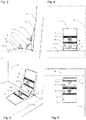
- the invention shows an angle connector (also referred to as a connection angle) ( Fig. 1 ), in which the angle can be continuously adjusted and fixed at the desired angle.
- a connection angle also referred to as a connection angle
- plates can be positively connected to one another at different, but nonetheless fixable, angles.
- the main parts (under this term both the first and the second main part are understood) of the invention consist of metallic (aluminum, steel etc.) or non-metallic (plastic) material, which is either extruded, in various casting processes, by means of printing processes or in machining can be produced.
- the two legs (also known as fixing legs) of the connecting bracket are connected to the panels to be connected using standardized second connecting means (e.g. undercut anchors, screws, rivets, anchors, dowels, rivet nuts, welding studs, etc.).
- the angle between the parts to be connected can then be freely selected in a defined area. This freely selected angle is fixed in that the two fixing legs are positively connected to one another. This is done, for example, by drilling a hole and attaching a rivet connection or by using a self-drilling screw.
- a metric screw with a thread in the rear of the two fixing legs is also conceivable.
- a groove running in opposite directions is also conceivable, which can be connected and thus fixed by means of metric screws and nuts.
- the fixing legs of the main parts can optionally be provided with grooves, which enables the desired angle to be set in stages and better fixation when the grooves interlock.
- the components can be adapted depending on the application, the basic idea of the invention being retained.
- different bores for different second connecting means of the plates to be connected can be made in the legs Drilled or milled, an elongated hole is shown as an example, which is fixed in the direction of the elongated hole by means of a grooved washer.
- the size and geometry of the variable and fixable angle connector can be adapted to the respective application.
- the position of the fixing legs is variable and can also be made adaptable to the application.
- the main part 1 has a flat support surface, a central pivot point 1a and a curved fixing leg 1b, which has the same pivot point as the central pivot point 1a.
- the main part 1 is shown in the illustration with an elongated hole 1c and grooves 1d running in opposite directions by 90 °. In fact, depending on the actual purpose, there are various possibilities for establishing the connection to plate 6 or plate 7.
- Main part 2 describes the counterpart to main part 1 and interacts with it to ensure adjustability.
- This main part 2 also has a flat support surface, a central pivot point 2a as a counterpart to the central pivot point 1a of main part 1 and a curved fixing leg 2b, which has the same pivot point as central pivot 2a, but is offset from fixing leg 1b of main part 1.
- the main part 2 is shown in the illustration with an elongated hole 2c and grooves 2d running in opposite directions by 90 °. In fact, depending on the actual purpose, there are various possibilities for establishing the connection to plate 6 or plate 7.
Landscapes
- Engineering & Computer Science (AREA)
- General Engineering & Computer Science (AREA)
- Mechanical Engineering (AREA)
- Architecture (AREA)
- Physics & Mathematics (AREA)
- Electromagnetism (AREA)
- Civil Engineering (AREA)
- Structural Engineering (AREA)
- Pivots And Pivotal Connections (AREA)
- Connection Of Plates (AREA)
- Mutual Connection Of Rods And Tubes (AREA)
Applications Claiming Priority (1)
| Application Number | Priority Date | Filing Date | Title |
|---|---|---|---|
| AT602092019A AT522697B1 (de) | 2019-09-16 | 2019-09-16 | Leibungswinkel verstell bar |
Publications (1)
| Publication Number | Publication Date |
|---|---|
| EP3792506A1 true EP3792506A1 (fr) | 2021-03-17 |
Family
ID=72432684
Family Applications (1)
| Application Number | Title | Priority Date | Filing Date |
|---|---|---|---|
| EP20020402.2A Withdrawn EP3792506A1 (fr) | 2019-09-16 | 2020-09-08 | Raccord angulaire pouvant être réglé et fixé de manière variable |
Country Status (2)
| Country | Link |
|---|---|
| EP (1) | EP3792506A1 (fr) |
| AT (1) | AT522697B1 (fr) |
Cited By (1)
| Publication number | Priority date | Publication date | Assignee | Title |
|---|---|---|---|---|
| CN120798934A (zh) * | 2025-07-09 | 2025-10-17 | 中鼎国际工程有限责任公司 | 一种装配式装套用预制安装卡扣件 |
Citations (7)
| Publication number | Priority date | Publication date | Assignee | Title |
|---|---|---|---|---|
| DE3633373A1 (de) * | 1986-10-01 | 1988-04-14 | Broekelmann Aluminium F W | Sparrenprofilanordnung fuer verglaste daecher von wintergaerten, veranden oder dergleichen |
| EP0652382A2 (fr) * | 1993-11-10 | 1995-05-10 | Herbert Burda | Dispositif de fixation pour canaux d'installation |
| DE19904503A1 (de) * | 1999-02-04 | 2000-08-10 | Pyratekt Glasdachkonstruktion | Glasdachkonstruktion |
| US6298619B1 (en) * | 2000-03-02 | 2001-10-09 | William D. Davie | Modular building frame system |
| DE202006013551U1 (de) | 2006-09-01 | 2006-11-02 | Kienle Ltd. & Co. Kg | Winkelverbinder zur Verbindung von flächenförmigen Abtrennungselementen |
| US20060254192A1 (en) | 2003-10-08 | 2006-11-16 | Fennell Harry C Jr | Construction Bracket and Method |
| EP2022902A2 (fr) | 2007-08-08 | 2009-02-11 | Getzner Werkstoffe Holding GmbH | Dispositif de liaison d'angle |
Family Cites Families (2)
| Publication number | Priority date | Publication date | Assignee | Title |
|---|---|---|---|---|
| DE202005012520U1 (de) * | 2005-08-05 | 2005-11-03 | Kunststoffwerke-Ggk Gmbh & Co. Kg | Hohlkanalanordnung zur Eckumfahrung |
| CN108360681B (zh) * | 2018-03-06 | 2019-11-12 | 南京工业大学 | 一种可变角度的木结构装配式连接节点 |
-
2019
- 2019-09-16 AT AT602092019A patent/AT522697B1/de not_active IP Right Cessation
-
2020
- 2020-09-08 EP EP20020402.2A patent/EP3792506A1/fr not_active Withdrawn
Patent Citations (7)
| Publication number | Priority date | Publication date | Assignee | Title |
|---|---|---|---|---|
| DE3633373A1 (de) * | 1986-10-01 | 1988-04-14 | Broekelmann Aluminium F W | Sparrenprofilanordnung fuer verglaste daecher von wintergaerten, veranden oder dergleichen |
| EP0652382A2 (fr) * | 1993-11-10 | 1995-05-10 | Herbert Burda | Dispositif de fixation pour canaux d'installation |
| DE19904503A1 (de) * | 1999-02-04 | 2000-08-10 | Pyratekt Glasdachkonstruktion | Glasdachkonstruktion |
| US6298619B1 (en) * | 2000-03-02 | 2001-10-09 | William D. Davie | Modular building frame system |
| US20060254192A1 (en) | 2003-10-08 | 2006-11-16 | Fennell Harry C Jr | Construction Bracket and Method |
| DE202006013551U1 (de) | 2006-09-01 | 2006-11-02 | Kienle Ltd. & Co. Kg | Winkelverbinder zur Verbindung von flächenförmigen Abtrennungselementen |
| EP2022902A2 (fr) | 2007-08-08 | 2009-02-11 | Getzner Werkstoffe Holding GmbH | Dispositif de liaison d'angle |
Cited By (1)
| Publication number | Priority date | Publication date | Assignee | Title |
|---|---|---|---|---|
| CN120798934A (zh) * | 2025-07-09 | 2025-10-17 | 中鼎国际工程有限责任公司 | 一种装配式装套用预制安装卡扣件 |
Also Published As
| Publication number | Publication date |
|---|---|
| AT522697B1 (de) | 2021-01-15 |
| AT522697A4 (de) | 2021-01-15 |
Similar Documents
| Publication | Publication Date | Title |
|---|---|---|
| EP3114359B1 (fr) | Dispositif servant à assembler un élément de structure à un élément de maintien selon un espacement l'un par rapport à l'autre | |
| DE20210133U1 (de) | Verbindung von Profilstreben | |
| EP2786026A1 (fr) | Barre profilée, assemblage de profilés et procédé de fabrication d'un assemblage de profilés | |
| DE3523155C2 (fr) | ||
| DE202009012750U1 (de) | Dübelbolzen einer Verbindungsvorrichtung | |
| EP1977124B1 (fr) | Dispositif pour maintenir et positionner des appareils, des pièces et des outils | |
| AT522697B1 (de) | Leibungswinkel verstell bar | |
| DE102011014835A1 (de) | Vorrichtung zum Verstellen einer Fläche eines Fluggerätemodells, Flächeneinheit, Fluggerätemodell und Verwendung eines Fluggerätemodells | |
| EP3047159B1 (fr) | Raccord de profilés et assemblage de profilés | |
| EP3429801B1 (fr) | Articulation pouvant être fixée à des positions équidistantes et groupe de composants doté d'une articulation de ce type | |
| DE202008011381U1 (de) | Halte-, Spann- und Positioniersystem für Geräte, Werkstücke und Werkzeuge | |
| DE10012729B4 (de) | Vorrichtung zum stirnseitigen Verbinden von Profilstäben | |
| EP3219891A1 (fr) | Système de charnière à réglage tridimensionnelle | |
| EP1813824A2 (fr) | Dispositif d'assemblage pour panneaux de meubles | |
| DE202007008969U1 (de) | Profilverbinder sowie Profilverbund | |
| AT506192B1 (de) | Verbindungselement | |
| DE202014005734U1 (de) | Bandaufnahmeelement | |
| DE102014217781A1 (de) | Vorrichtung zum Befestigen eines Verkleidungselements | |
| DE10050143A1 (de) | Bolzensicherung | |
| DE60300443T2 (de) | Schraubenverbindung, insbesondere für geschlitzte Profilschienen | |
| DE102014206383A1 (de) | Befestigungssystem bei einseitiger Zugänglichkeit | |
| EP4080068B1 (fr) | Connecteur pour deux composants | |
| DE102005051215B4 (de) | Einstellbare Befestigung von Fahrzeugtüren | |
| EP3517793B1 (fr) | Dispositif de raccordement de tuyaux | |
| AT3665U1 (de) | Beschlag zur befestigung von griffen |
Legal Events
| Date | Code | Title | Description |
|---|---|---|---|
| PUAI | Public reference made under article 153(3) epc to a published international application that has entered the european phase |
Free format text: ORIGINAL CODE: 0009012 |
|
| STAA | Information on the status of an ep patent application or granted ep patent |
Free format text: STATUS: THE APPLICATION HAS BEEN PUBLISHED |
|
| AK | Designated contracting states |
Kind code of ref document: A1 Designated state(s): AL AT BE BG CH CY CZ DE DK EE ES FI FR GB GR HR HU IE IS IT LI LT LU LV MC MK MT NL NO PL PT RO RS SE SI SK SM TR |
|
| AX | Request for extension of the european patent |
Extension state: BA ME |
|
| STAA | Information on the status of an ep patent application or granted ep patent |
Free format text: STATUS: THE APPLICATION IS DEEMED TO BE WITHDRAWN |
|
| 18D | Application deemed to be withdrawn |
Effective date: 20210918 |