EP3792636A2 - Procédé de commande d'appareil rotatif et son dispositif électronique - Google Patents
Procédé de commande d'appareil rotatif et son dispositif électronique Download PDFInfo
- Publication number
- EP3792636A2 EP3792636A2 EP20202364.4A EP20202364A EP3792636A2 EP 3792636 A2 EP3792636 A2 EP 3792636A2 EP 20202364 A EP20202364 A EP 20202364A EP 3792636 A2 EP3792636 A2 EP 3792636A2
- Authority
- EP
- European Patent Office
- Prior art keywords
- rotating body
- indicators
- rotation
- electronic device
- rotation parameter
- Prior art date
- Legal status (The legal status is an assumption and is not a legal conclusion. Google has not performed a legal analysis and makes no representation as to the accuracy of the status listed.)
- Withdrawn
Links
Images


Classifications
-
- G—PHYSICS
- G05—CONTROLLING; REGULATING
- G05D—SYSTEMS FOR CONTROLLING OR REGULATING NON-ELECTRIC VARIABLES
- G05D3/00—Control of position or direction
- G05D3/12—Control of position or direction using feedback
- G05D3/20—Control of position or direction using feedback using a digital comparing device
- G05D3/203—Control of position or direction using feedback using a digital comparing device using fine or coarse devices
-
- H—ELECTRICITY
- H02—GENERATION; CONVERSION OR DISTRIBUTION OF ELECTRIC POWER
- H02P—CONTROL OR REGULATION OF ELECTRIC MOTORS, ELECTRIC GENERATORS OR DYNAMO-ELECTRIC CONVERTERS; CONTROLLING TRANSFORMERS, REACTORS OR CHOKE COILS
- H02P23/00—Arrangements or methods for the control of AC motors characterised by a control method other than vector control
- H02P23/14—Estimation or adaptation of motor parameters, e.g. rotor time constant, flux, speed, current or voltage
-
- G—PHYSICS
- G01—MEASURING; TESTING
- G01P—MEASURING LINEAR OR ANGULAR SPEED, ACCELERATION, DECELERATION, OR SHOCK; INDICATING PRESENCE, ABSENCE, OR DIRECTION, OF MOVEMENT
- G01P3/00—Measuring linear or angular speed; Measuring differences of linear or angular speeds
- G01P3/42—Devices characterised by the use of electric or magnetic means
- G01P3/56—Devices characterised by the use of electric or magnetic means for comparing two speeds
-
- G—PHYSICS
- G01—MEASURING; TESTING
- G01B—MEASURING LENGTH, THICKNESS OR SIMILAR LINEAR DIMENSIONS; MEASURING ANGLES; MEASURING AREAS; MEASURING IRREGULARITIES OF SURFACES OR CONTOURS
- G01B11/00—Measuring arrangements characterised by the use of optical techniques
- G01B11/26—Measuring arrangements characterised by the use of optical techniques for measuring angles or tapers; for testing the alignment of axes
-
- G—PHYSICS
- G01—MEASURING; TESTING
- G01D—MEASURING NOT SPECIALLY ADAPTED FOR A SPECIFIC VARIABLE; ARRANGEMENTS FOR MEASURING TWO OR MORE VARIABLES NOT COVERED IN A SINGLE OTHER SUBCLASS; TARIFF METERING APPARATUS; MEASURING OR TESTING NOT OTHERWISE PROVIDED FOR
- G01D5/00—Mechanical means for transferring the output of a sensing member; Means for converting the output of a sensing member to another variable where the form or nature of the sensing member does not constrain the means for converting; Transducers not specially adapted for a specific variable
- G01D5/26—Mechanical means for transferring the output of a sensing member; Means for converting the output of a sensing member to another variable where the form or nature of the sensing member does not constrain the means for converting; Transducers not specially adapted for a specific variable characterised by optical transfer means, i.e. using infrared, visible, or ultraviolet light
- G01D5/32—Mechanical means for transferring the output of a sensing member; Means for converting the output of a sensing member to another variable where the form or nature of the sensing member does not constrain the means for converting; Transducers not specially adapted for a specific variable characterised by optical transfer means, i.e. using infrared, visible, or ultraviolet light with attenuation or whole or partial obturation of beams of light
- G01D5/34—Mechanical means for transferring the output of a sensing member; Means for converting the output of a sensing member to another variable where the form or nature of the sensing member does not constrain the means for converting; Transducers not specially adapted for a specific variable characterised by optical transfer means, i.e. using infrared, visible, or ultraviolet light with attenuation or whole or partial obturation of beams of light the beams of light being detected by photocells
- G01D5/347—Mechanical means for transferring the output of a sensing member; Means for converting the output of a sensing member to another variable where the form or nature of the sensing member does not constrain the means for converting; Transducers not specially adapted for a specific variable characterised by optical transfer means, i.e. using infrared, visible, or ultraviolet light with attenuation or whole or partial obturation of beams of light the beams of light being detected by photocells using displacement encoding scales
-
- G—PHYSICS
- G01—MEASURING; TESTING
- G01P—MEASURING LINEAR OR ANGULAR SPEED, ACCELERATION, DECELERATION, OR SHOCK; INDICATING PRESENCE, ABSENCE, OR DIRECTION, OF MOVEMENT
- G01P13/00—Indicating or recording presence, absence, or direction, of movement
- G01P13/02—Indicating direction only, e.g. by weather vane
- G01P13/04—Indicating positive or negative direction of a linear movement or clockwise or anti-clockwise direction of a rotational movement
-
- G—PHYSICS
- G01—MEASURING; TESTING
- G01P—MEASURING LINEAR OR ANGULAR SPEED, ACCELERATION, DECELERATION, OR SHOCK; INDICATING PRESENCE, ABSENCE, OR DIRECTION, OF MOVEMENT
- G01P21/00—Testing or calibrating of apparatus or devices covered by the preceding groups
- G01P21/02—Testing or calibrating of apparatus or devices covered by the preceding groups of speedometers
-
- G—PHYSICS
- G01—MEASURING; TESTING
- G01P—MEASURING LINEAR OR ANGULAR SPEED, ACCELERATION, DECELERATION, OR SHOCK; INDICATING PRESENCE, ABSENCE, OR DIRECTION, OF MOVEMENT
- G01P3/00—Measuring linear or angular speed; Measuring differences of linear or angular speeds
- G01P3/42—Devices characterised by the use of electric or magnetic means
- G01P3/44—Devices characterised by the use of electric or magnetic means for measuring angular speed
- G01P3/48—Devices characterised by the use of electric or magnetic means for measuring angular speed by measuring frequency of generated current or voltage
- G01P3/481—Devices characterised by the use of electric or magnetic means for measuring angular speed by measuring frequency of generated current or voltage of pulse signals
- G01P3/486—Devices characterised by the use of electric or magnetic means for measuring angular speed by measuring frequency of generated current or voltage of pulse signals delivered by photo-electric detectors
-
- G—PHYSICS
- G01—MEASURING; TESTING
- G01P—MEASURING LINEAR OR ANGULAR SPEED, ACCELERATION, DECELERATION, OR SHOCK; INDICATING PRESENCE, ABSENCE, OR DIRECTION, OF MOVEMENT
- G01P3/00—Measuring linear or angular speed; Measuring differences of linear or angular speeds
- G01P3/42—Devices characterised by the use of electric or magnetic means
- G01P3/50—Devices characterised by the use of electric or magnetic means for measuring linear speed
- G01P3/54—Devices characterised by the use of electric or magnetic means for measuring linear speed by measuring frequency of generated current or voltage
-
- G—PHYSICS
- G05—CONTROLLING; REGULATING
- G05B—CONTROL OR REGULATING SYSTEMS IN GENERAL; FUNCTIONAL ELEMENTS OF SUCH SYSTEMS; MONITORING OR TESTING ARRANGEMENTS FOR SUCH SYSTEMS OR ELEMENTS
- G05B15/00—Systems controlled by a computer
- G05B15/02—Systems controlled by a computer electric
-
- G—PHYSICS
- G05—CONTROLLING; REGULATING
- G05D—SYSTEMS FOR CONTROLLING OR REGULATING NON-ELECTRIC VARIABLES
- G05D13/00—Control of linear speed; Control of angular speed; Control of acceleration or deceleration, e.g. of a prime mover
-
- G—PHYSICS
- G01—MEASURING; TESTING
- G01D—MEASURING NOT SPECIALLY ADAPTED FOR A SPECIFIC VARIABLE; ARRANGEMENTS FOR MEASURING TWO OR MORE VARIABLES NOT COVERED IN A SINGLE OTHER SUBCLASS; TARIFF METERING APPARATUS; MEASURING OR TESTING NOT OTHERWISE PROVIDED FOR
- G01D5/00—Mechanical means for transferring the output of a sensing member; Means for converting the output of a sensing member to another variable where the form or nature of the sensing member does not constrain the means for converting; Transducers not specially adapted for a specific variable
- G01D5/26—Mechanical means for transferring the output of a sensing member; Means for converting the output of a sensing member to another variable where the form or nature of the sensing member does not constrain the means for converting; Transducers not specially adapted for a specific variable characterised by optical transfer means, i.e. using infrared, visible, or ultraviolet light
- G01D5/32—Mechanical means for transferring the output of a sensing member; Means for converting the output of a sensing member to another variable where the form or nature of the sensing member does not constrain the means for converting; Transducers not specially adapted for a specific variable characterised by optical transfer means, i.e. using infrared, visible, or ultraviolet light with attenuation or whole or partial obturation of beams of light
- G01D5/34—Mechanical means for transferring the output of a sensing member; Means for converting the output of a sensing member to another variable where the form or nature of the sensing member does not constrain the means for converting; Transducers not specially adapted for a specific variable characterised by optical transfer means, i.e. using infrared, visible, or ultraviolet light with attenuation or whole or partial obturation of beams of light the beams of light being detected by photocells
- G01D5/347—Mechanical means for transferring the output of a sensing member; Means for converting the output of a sensing member to another variable where the form or nature of the sensing member does not constrain the means for converting; Transducers not specially adapted for a specific variable characterised by optical transfer means, i.e. using infrared, visible, or ultraviolet light with attenuation or whole or partial obturation of beams of light the beams of light being detected by photocells using displacement encoding scales
- G01D5/34776—Absolute encoders with analogue or digital scales
- G01D5/34792—Absolute encoders with analogue or digital scales with only digital scales or both digital and incremental scales
Definitions
- the present disclosure relates to an electronic device. More particularly, the present disclosure relates to an apparatus and a method for controlling a rotating body in an electronic device.
- a method for controlling a device e.g., a rotating body to drive a driving body
- a device e.g., a rotating body
- such a device may be controlled by installing a limit switch therein such that an electronic device electrically senses the limit switch installed in the corresponding device.
- the device may be controlled by calculating a rotation amount of the device which rotates and controlling a rotation speed of the device.
- a device of the related art e.g., a rotating body
- a rotating body for driving the driving body is subject to a rotation deviation of the rotating body according to continuous motor control (e.g., motor abrasion) and an uneven revolutions per minute (RPM) of a motor as time passes.
- continuous motor control e.g., motor abrasion
- RPM revolutions per minute
- the rotating body for driving the driving body may repeat an existing operation and have difficulty in rapidly finding a starting point (e.g., a reference position) of the device.
- an aspect of the present disclosure is to provide an apparatus and a method for detecting a rotation parameter of a rotating body based on an amount of received light corresponding to indicators having different reflectivities of the rotating body, and controlling the rotating body based on the detected rotation parameter in an electronic device.
- a method for operating an electronic device includes emitting light to at least one indicator among a plurality of indicators having different reflectivities in a rotating body, receiving light reflected from the at least one indicator, detecting a rotation parameter of the rotating body based on an amount of the reflected light received from the at least one indicator, and controlling the rotating body based on the rotation parameter.
- an electronic device in accordance with another aspect of the present disclosure, includes a rotating body comprising a plurality of indicators having different reflectivities, a detector comprising a light emitter configured to emit light to at least one indicator of the plurality of indicators and a light receiver configured to receive light reflected from the at least one indicator, and a processor configured to detect a rotation parameter of the rotating body based on an amount of the reflected light received from the at least one indicator, and to control the rotating body based on the rotation parameter.
- an expression “A or B”, “A and/or B”, or “one or more of A and/or B” or the like may include all possible combinations of items enumerated together.
- “A or B”, “at least one of A and B”, or “at least one of A or B” may indicate all cases where (1) at least one A is included, (2) at least one B is included, and (3) at least one A and at least one B are both included.
- a certain element e.g., the 1st element
- a different element e.g., the 2nd element
- the certain element is directly coupled with/to another element or may be coupled with/to the different element via another element (e.g., a 3rd constitutional element).
- the certain element e.g., the 1st element
- another element e.g., the 3rd constitutional element
- An expression “configured to” used in the present disclosure may be interchangeably used with, for example, “suitable for”, “having the capacity to”, “designed to”, “adapted to”, “made to”, or “capable of' according to a situation.
- a term “configured to” may not imply only “specially designed to” in a hardware manner. Instead, in a certain situation, an expressed "a device configured to” may imply that the device is “capable of' together with other devices or components.
- a processor configured to perform A, B, and C may imply a dedicated processor (e.g., an embedded processor) for performing a corresponding operation or a generic-purpose processor (e.g., central processing unit (CPU) or an application processor) capable of performing corresponding operations by executing one or more software programs stored in a memory device.
- a dedicated processor e.g., an embedded processor
- a generic-purpose processor e.g., central processing unit (CPU) or an application processor
- An electronic device may include at least one of a smart phone, a tablet personal computer (PC), a mobile phone, a video phone, an e-book reader, a desktop PC, a laptop PC, a netbook computer, a workstation, a server, a personal digital assistant (PDA), a portable multimedia player (PMP), a Moving Picture Experts Group phase 1 or phase 2 (MPEG-1 or MPEG-2) audio layer 3 (MP3) player, a mobile medical device, a camera, and a wearable device (e.g., smart glasses, a head-mounted-device (HMD), a smart mirror, or a smart watch).
- PDA personal digital assistant
- PMP portable multimedia player
- MPEG-1 or MPEG-2 Moving Picture Experts Group phase 1 or phase 2
- MP3 audio layer 3
- the electronic device may be a smart home appliance.
- the smart home appliance may include at least one of a television (TV), a digital versatile disc (DVD) player, an audio device, a refrigerator, an air conditioner, a cleaner, an oven, a microwave oven, a washing machine, an air purifier, a set-top box, a home automation control panel, a security control panel, a TV box (e.g., Samsung HomeSyncTM, Apple TVTM, or Google TVTM), a game console (e.g., XboxTM, PlayStationTM), and a camcorder.
- TV television
- DVD digital versatile disc
- the electronic device may include at least one of various medical devices (e.g., various portable medical measurement devices (i.e., a blood glucose monitoring device, a heart rate monitoring device, a blood pressure measuring device, a body heat measuring device, etc.), magnetic resonance angiography (MRA), magnetic resonance imaging (MRI), computed tomography (CT), imaging equipment, ultrasonic instrument, etc.), a navigation device, a global positioning system (GPS) receiver, an event data recorder (EDR), a flight data recorder (FDR), a car infotainment device, an electronic equipment for a ship (e.g., a vessel navigation device, a gyro compass, etc.), avionics, a security device, a vehicle head unit, an industrial or domestic robot, an automatic teller machine (ATM) of a financial institution, a point of sales (POS) of a retail shop, and devices associated with the Internet of things (e.g., a light bulb, various sensors, etc.
- the electronic device may include at least one of furniture, a part of a building/construction, an electronic board, an electronic signature receiving device, a projector, and various measurement machines (e.g., water supply, electricity, gas, propagation measurement machine, etc.).
- various measurement machines e.g., water supply, electricity, gas, propagation measurement machine, etc.
- the electronic device may be one or more combinations of the aforementioned various devices.
- the electronic device may be a flexible device.
- the electronic device according to the various embodiments of the present disclosure is not limited to the aforementioned devices, and may include a new electronic device based on technical advances.
- a term 'user' may refer to a person who uses the electronic device or a device which uses the electronic device (e.g., an artificial intelligence (AI) electronic device).
- AI artificial intelligence
- various embodiments of the present disclosure provide a technique for controlling a rotating body (or a rotator) in an electronic device.
- FIG. 1 is a block diagram of an electronic device according to an embodiment of the present disclosure.
- the electronic device 100 may include a processor (or a controller) 110, a display unit (or a display) 120, a memory 130, an input unit 140, a detector 150, and a rotating body 160.
- the electronic device 100 may omit at least one of those components, or include another component.
- the electronic device 100 may further include a bus which is a circuit for interconnecting the components (e.g., the processor 110, the display unit 120, the memory 130, the input unit 140, a detector 150, and the rotating body 160) and delivering communications (e.g., control messages) between the components.
- a bus which is a circuit for interconnecting the components (e.g., the processor 110, the display unit 120, the memory 130, the input unit 140, a detector 150, and the rotating body 160) and delivering communications (e.g., control messages) between the components.
- the processor 110 may include one or more of a CPU and an application processor (AP).
- the processor 110 may, for example, control at least one other component of the electronic device 100 and/or process communication operation or data.
- the processor 110 may control to emit light to at least part of indicators having different reflectivities of the rotating body 160.
- the indicators may have different reflectivities using at least one of different colors, saturations, and marks.
- the processor 110 may control a light emitter of the detector 150 to emit the light to one or more indicators disposed on an outer surface of the rotating body 160.
- the processor 110 may control to receive light reflected from the indicators. For example, using a light receiver of the detector 150, the processor 110 may detect an amount of the received light reflected from one or more indicators disposed on the outer surface of the rotating body 160. For example, using the detector 150, the processor 110 may detect the amount of the received light reflected from one or more reference indicators disposed at a reference position of the rotating body 160.
- the processor 110 may detect a rotation parameter of the rotating body 160 based on the received amount of light corresponding to the indicators of the rotating body 160.
- the rotation parameter may include at least one of a reference position, a rotation speed, a rotation angle, a rotation direction, and a rotation amount of the rotating body 160.
- the processor 110 may have a table of values of received amounts of light corresponding to one or more indicators disposed in the outer surface of the rotating body 160. That is, the processor 110 may determine which indicator(s) the detected received amount of light corresponds to.
- the processor 110 may detect the rotation parameter of the rotating body 160 by comparing the received amount of light corresponding to the indicators with the table of values of received amounts of light.
- the processor 110 may detect a malfunction of the rotating body 160 based on the rotation parameter of the rotating body 160.
- the malfunction of the rotating body 160 indicates a rotation speed deviation of the rotating body 160.
- the malfunction of the rotating body 160 may be caused by an external pressure or shock.
- the processor 110 may detect the malfunction of the rotating body 160 by comparing at least one of the rotation speed, the rotation angle, and the rotation amount of the rotation parameter with at least one of a reference rotation speed, a reference rotation angle, and a reference rotation amount.
- the processor 110 may re-drive the rotating body 160 based on the reference position of the rotation parameter of the rotating body 160.
- the processor 110 may stop the driving the rotating body 160.
- the processor 110 may turn the rotating body 160 to the reference position of the rotation parameter and then re-drive the rotating body 160.
- the processor 110 may turn the rotating body 160 from a current position to the reference position and then re-drive the rotating body 160.
- the rotation parameter includes a plurality of reference positions
- the processor 110 may turn the rotating body 160 to a reference position near the current location and then re-drive the rotating body 160.
- the processor 110 may correct the rotation speed of the rotating body 160 based on the rotation parameter of the rotating body 160. For example, the processor 110 may compare the detected rotation parameter with a reference rotation parameter and thus correct the rotation speed of the rotating body 160 based on a calculated correction value. For example, the processor 110 may calculate the correction value of the rotation speed by determining how much the rotation speed of the detected rotation parameter is lower or higher than the reference rotation speed. The processor 110 may correct the rotation speed of the rotating body 160 based on the calculated correction value. That is, when the detected rotation speed is lower than the reference rotation speed, the processor 110 may increase the rotation speed of the rotating body 160. When the detected rotation speed is higher than the reference rotation speed, the processor 110 may decrease the rotation speed of the rotating body 160.
- the display unit 120 may include a display for displaying data such as various contents (e.g., texts, images, video, icons, or symbols).
- the display unit 120 may include a liquid crystal display (LCD), a light emitting diode (LED) display, an organic LED (OLED) display, a microelectromechanical system (MEMS) display, or an electronic paper display.
- LCD liquid crystal display
- LED light emitting diode
- OLED organic LED
- MEMS microelectromechanical system
- the memory 130 may store a command or data (e.g., device performance) relating to at least one other component of the electronic device 100.
- the memory 130 may store an application program installed in the electronic device 100 and software and/or program for operating the electronic device 100.
- the memory 130 may have the table of values of the received amounts of light corresponding to the indicators of the rotating body 160.
- the memory 130 may include a volatile memory and/or a non-volatile memory.
- the input unit 140 may include an input means for forwarding a command or data input from a user or an external device to the other component(s) of the electronic device 100.
- the input unit 140 may include a key pad, a dome switch, a physical button, a touch panel, a jog & shuttle, and a sensor.
- the detector 150 may include a light emitter for emitting light to at least part of the indicators having the different reflectivities in the outer surface of the rotating body 160, and a light receiver for receiving the light reflected from the indicators. For example, the detector 150 may detect the received amount of light by receiving the light reflected from the indicators disposed in the outer surface of the rotating body 160. The detector 150 may provide the detected received amount of light to the processor 110.
- the detector 150 may employ, but not limited to, a photosensor including an infrared LED.
- the rotating body 160 may make a rotary motion under control of the processor 110.
- the rotating body 160 may include the rotation parameter according to the rotary motion.
- the rotation parameter may include at least one of the reference position, the rotation speed, the rotation angle, the rotation direction, and the rotation amount of the rotating body 160.
- the indicators having the different reflectivities may be disposed in the outer surface of the rotating body 160.
- the indicators may have the different reflectivities using at least one of different colors, saturations, and marks.
- the indicators may be disposed at regular or different intervals on at least one of an upper surface, a lower surface, an outside surface, and an inside surface of the rotating body 160.
- some of the indicators of the rotating body 160 may indicate the reference position of the rotating body 160.
- the reference position may be a starting point where a series of operations commences.
- FIG. 2 is a block diagram of a processor according to an embodiment of the present disclosure.
- the processor 110 may include a rotation parameter detector 200, a motor controller 210, and a driver integrated circuit (IC) 220.
- the processor 110 may omit at least one of the components and further include another element.
- the motor controller 210 and the driver IC 220 may be constructed independently from the processor 110 and controlled by the processor 110.
- the detector 150 may emit the light to at least some of the indicators having the different reflectivities on the outer surface of the rotating body 1690, and detect the received amount of light by receiving the light reflected from the indicators. For example, the detector 150 may provide the detected received amount of light to the rotation parameter detector 200.
- the rotation parameter detector 200 may receive from the detector 150 the received amount of light corresponding to the indicators of the rotating body 160.
- the rotation parameter detector 200 may detect the rotation parameter of the rotating body 160 based on the received light amount.
- the rotation parameter may include at least one of the reference position, the rotation speed, the rotation angle, the rotation direction, and the rotation amount of the rotating body 160.
- the rotation parameter detector 200 may control the rotating body 160 based on the detected rotation parameter. For example, the rotation parameter detector 200 may provide a driving signal of the rotating body 160 to the motor controller 210 based on the detected rotation parameter.
- the motor controller 210 may receive the driving signal of the rotating body 160 from the rotation parameter detector 200.
- the motor controller 210 may control the motor 170 through the driver IC 220.
- the motor controller 210 may forward the driving signal of the rotating body 160 to the driver IC 220.
- the driver IC 220 may receive the driving signal of the rotating body 160 from the motor controller 210. For example, the driver IC 220 may convert the received driving signal to a motor driving power and provide the motor driving power to the motor 170.
- the motor 170 may be driven with the power from the driver IC 220, and rotate the rotating body 160 at a constant rotation speed.
- the motor 170 may be driven with a torque and a revolutions per minute (RPM) defined through gear ratio control.
- RPM revolutions per minute
- the rotating body 160 may be rotated by the motor 170 at a constant rotation speed.
- the indicators having the different reflectivities may be disposed on the outer surface of the rotating body 160.
- FIG. 3 depicts a rotating body including indicators according to an embodiment of the present disclosure.
- the rotating body 300 may be formed in a circle based on a rotation axis 320.
- the rotating body 300 may rotate based on the rotation axis 320 (e.g., x axis).
- the rotating body 300 may have a rotation parameter according to the rotation.
- a rotation parameter may include at least one of the reference position, the rotation speed, the rotation angle, the rotation direction, and the rotation amount of the rotating body.
- the outer surface 310 of the rotating body 300 may include the indicators 311, 312, and 313 having the different reflectivities.
- the indicators 311, 312, and 313 may be disposed at regular or different intervals on the outside surface of the rotating body 300.
- some indicators 311 of the indicators 311, 312, and 313 may indicate a reference position of the rotating body 300. The reference position may be a starting point where a series of operations of the rotating body 300 commences.
- the detector 330 may emit light to at least some of the indicators 311, 312, and 313 on the outside surface of the rotating body 300, and receive the light reflected from the indicators 311, 312, and 313.
- the detector 330 may emit light to one or more indicators and receive the light reflected from one or more indicators.
- the indicators 311, 312, and 313 may have different reflectivities using at least one of different colors, saturations, and marks.
- the indicators 311, 312, and 313 may include, but not limited to, tapes, paints, or films having different reflectivities.
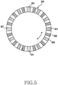
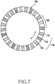
- FIGS. 4 to 7 depict a pattern of indicators disposed in the rotating body of FIG. 3 according to various embodiments of the present disclosure.
- a pattern 400 of the indicators includes indicators 401, 402, and 403 of three types.
- the indicators 401, 402, and 403 may have different reflectivities using at least one of different colors, saturations, and marks.
- some 401 of the indicators 401, 402, and 403 may indicate a reference position.
- the remaining indicators 402 and 403 may be disposed, but not limited to, in order or at random.
- a pattern 500 of the indicators includes indicators 501, 502, and 503 of three types.
- the indicators 501, 502, and 503 may have different reflectivities using at least one of different colors, saturations, and marks.
- some 501 of the indicators 501, 502, and 503 may indicate a reference position.
- Some indicators 501 indicating the reference position may be disposed at regular intervals.
- some indicators 501 may be disposed at, but not limited to, 90 degrees, 180 degrees, 270 degrees, and 360 degrees.
- some indicators 501 may have the same reflectivity or different reflectivities.
- the remaining indicators 502 and 503 may be disposed in order or at random.
- a pattern 600 of the indicators includes indicators 601, 602, 603, 604, 605, and 606 of six types.
- the indicators 601, 602, 603, 604, 605, and 606 may have different reflectivities using at least one of different colors, saturations, and marks.
- some 601 of the indicators 601, 602, 603, 604, 605, and 606 may indicate a reference position.
- the some indicators 601 indicating the reference position may be disposed at regular intervals.
- the some indicators 601 may be disposed at, but not limited to, 90 degrees, 180 degrees, 270 degrees, and 360 degrees.
- some indicators 601 may have the same reflectivity or different reflectivities.
- the remaining indicators 602, 603, 604, 605, and 606 may be disposed in order or at random.
- the remaining indicators 602, 603, 604, 605, and 606 may create patterns 607, and such patterns 607 may be arranged at regular or different intervals.
- a pattern 700 of the indicators includes indicators 701, 702, and 703 of three types.
- the indicators 701, 702, and 703 may have different reflectivities using at least one of different colors, saturations, and marks.
- the indicators 701, 702, and 703 may create a plurality of patterns 704 and 705, and some of the patterns 704 and 705 may indicate a reference position.
- a plurality of patterns 705 may indicate the reference position.
- the number, the pattern, or the type of the indicators on the outside surface of the rotating body may increase or decrease.
- the indicators may be disposed on not only the outside surface of the rotating body but also at least one of an upper surface, a lower surface, and an inside surface of the rotating body.
- the indicators may be applied to not only the rotating body which makes the rotational motion but also a device which makes a linear motion.
- An electronic device may include a rotating body comprising a plurality of indicators having different reflectivities, a detector comprising a light emitter which emits light to at least some of the indicators and a light receiver which receives light reflected from the indicators, and a processor for detecting a rotation parameter of the rotating body based on an amount of the received light corresponding to the indicators, and controlling the rotating body based on the rotation parameter.
- the rotation parameter may include at least one of a reference position, a rotation speed, a rotation angle, a rotation direction, and a rotation amount of the rotating body.
- the processor may determine based on the rotation parameter whether a malfunction of the rotating body occurs, and correct driving of the rotating body based on the rotation parameter in response to the malfunction of the rotating body.
- the processor may drive the rotating body based on a reference position of the rotating body of the rotation parameter.
- the processor may correct a rotation speed of the rotating body based on the rotation parameter.
- the processor may determine whether driving of the rotating body abnormally stops, in response to the abnormal stopping of the rotating body, set a reference position of the rotating body to a driving start position based on reference position information of the rotating body of the rotation parameter, and drive the rotating body based on the driving start position.
- the processor may detect the reference position of the rotating body based on an amount of the received light corresponding to at least one reference indicator of the indicators.
- the indicators may have the different reflectivities using at least one of different colors, saturations, and marks.
- the indicators may include at least one of tapes, paints, and films having different reflectivies.
- the detector may be a photosensor comprising an infrared LED.
- FIG. 8 illustrates a method for controlling a rotating body based on a rotation parameter in an electronic device according to an embodiment of the present disclosure.
- an electronic device may control to emit light to at least some of indicators having different reflectivities in a rotating body (e.g., the rotating body 160).
- the indicators may have the different reflectivities using at least one of different colors, saturations, and marks.
- the indicators may be disposed at regular or different intervals along an outer surface (e.g., an upper surface, a lower surface, an outside surface, or an inside surface) of the rotating body.
- the electronic device may control to emit the light to at least some of the indicators on the outer surface of the rotating body using a detector (e.g., the detector 150) functionally connected.
- the detector may be a photosensor including an infrared LED.
- the electronic device may control the light emitter of the detector to emit the light to one or more indicators on the outer surface of the rotating body.
- the electronic device may control to receive the light reflected from the indicators. For example, using the light receiver of the detector, the electronic device may detect the amount of the received light reflected from one or more indicators on the outer surface of the rotating body. For example, using the detector, the electronic device may detect the amount of the received light reflected from one or more indicators disposed at the reference position of the rotating body.
- the electronic device may detect the rotation parameter of the rotating body based on the received amount of light corresponding to the indicators.
- the rotation parameter may include at least one of the reference position, the rotation speed, the rotation angle, the rotation direction, and the rotation amount of the rotating body.
- the electronic device may have a table of values of the received amounts of light corresponding to one or more indicators disposed in the outer surface of the rotating body. That is, the electronic device may determine which indicator(s) the detected received amount of light corresponds to.
- the electronic device may detect the rotation parameter of the rotating body by comparing the received amount of light corresponding to the indicators with the table of values of the received amounts of light.
- the electronic device may control the rotating body based on the rotation parameter. For example, the electronic device may correct the driving of the rotating body based on the rotation parameter in response to a malfunction of the rotating body. For example, the electronic device may drive the rotating body based on the reference position of the rotating body of the rotation parameter in response to a malfunction of the rotating body. For example, the electronic device may correct the rotation speed of the rotating body based on the rotation parameter in response to a malfunction of the rotating body.
- FIG. 9 is a flowchart of a method for controlling a rotating body based on a reference position in an electronic device according to an embodiment of the present disclosure.
- an electronic device may drive a rotating body (e.g., the rotating body 160).
- a rotating body e.g., the rotating body 160
- the electronic device may drive the rotating body by controlling a motor driving module (e.g., the motor controller 210 and the motor 170).
- the electronic device may detect a rotation parameter of the rotating body based on the received amount of light corresponding to the indicators. For example, the electronic device may detect the rotation parameter based on the received amount of light corresponding to the indicators having the different reflectivities of the rotating body in operation 800 through 820 of FIG. 8 .
- the electronic device may determine based on the rotation parameter whether a malfunction of the rotating body occurs.
- the malfunction of the rotating body indicates a rotation speed deviation in the rotating body.
- the malfunction of the rotating body may be caused by an external pressure or shock.
- the electronic device may detect the malfunction of the rotating body by comparing at least one of the rotation speed, the rotation angle, and the rotation amount of the rotation parameter with at least one of the reference rotation speed, the reference rotation angle, and the reference rotation amount.
- the electronic device may re-drive the rotating body based on the reference position of the rotation parameter in operation 930. In response to the malfunction of the rotating body, the electronic device may stop the driving of the rotating body.
- the electronic device may turn the rotating body to the reference position of the rotation parameter and then re-drive the rotating body.
- the electronic device may turn the rotating body from a current position to the reference position and then re-drive the rotating body.
- the rotation parameter includes a plurality of reference positions
- the electronic device may turn the rotating body to the reference position near the current location and then re-drive the rotating body.
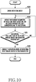
- FIG. 10 is a flowchart of a method for controlling a rotating body based on a rotation parameter in an electronic device according to an embodiment of the present disclosure.
- an electronic device may drive a rotating body (e.g., the rotating body 160).
- a rotating body e.g., the rotating body 160
- the electronic device may drive the rotating body by controlling a motor driving module (e.g., the motor controller 210 and the motor 170).
- the electronic device may detect a rotation parameter of the rotating body based on a received amount of light corresponding to indicators. For example, the electronic device may detect the rotation parameter based on the received amount of light corresponding to the indicators having the different reflectivities of the rotating body in operation 800 through 820 of FIG. 8 .
- the electronic device may determine based on the rotation parameter whether a malfunction of the rotating body occurs.
- the malfunction of the rotating body indicates a rotation speed deviation in the rotating body.
- the malfunction of the rotating body may be caused by an external pressure or shock.
- the electronic device may detect the malfunction of the rotating body by comparing at least one of the rotation speed, the rotation angle, and the rotation amount of the rotation parameter with at least one of the reference rotation speed, the reference rotation angle, and the reference rotation amount.
- the electronic device may correct a rotation speed of the rotating body based on the rotation parameter in operation 1030. For example, the electronic device may compare the detected rotation parameter with a reference rotation parameter and thus correct the rotation speed of the rotating body based on a calculated correction value. For example, the electronic device may determine how much the rotation speed of the detected rotation parameter is lower or higher than the reference rotation speed, and thus calculate the correction value of the rotation speed. The electronic device may correct the rotation speed of the rotating body based on the calculated correction value. That is, when the detected rotation parameter is lower than the reference rotation speed, the electronic device may increase the rotation speed of the rotating body. When the detected rotation parameter is higher than the reference rotation speed, the electronic device may decrease the rotation speed of the rotating body.
- FIG. 11 is a flowchart of a method for controlling a rotating body based on a reference position in an electronic device according to an embodiment of the present disclosure.
- an electronic device may determine whether a driving signal of a rotating body (e.g., the rotating body 160) is detected. For example, the electronic device may determine whether the rotating body driving signal is detected while the driving of the rotating body is stopped.
- the electronic device may determine whether a reference position of the rotating body is detected in operation 1110. For example, the electronic device may emit the light to at least some of the indicators having different reflectivities of the rotating body while the rotating body stops its driving, receive the light reflected from the indicators, and determine based on the received amount of light corresponding to the indicators whether the reference position of the rotating body is detected.
- the electronic device may drive the rotating body in operation 1140.
- the electronic device may rotate the rotating body in operation 1120.
- the electronic device may rotate the rotating body at a constant speed so as to detect the reference position of the rotating body.
- the electronic device may detect the reference position of the rotating body based on the received amount of light corresponding to the indicators. For example, the electronic device may detect the reference position based on the received amount of light corresponding to the indicators having the different reflectivities of the rotating body in operation 800 through 820 of FIG. 8 .
- the electronic device may drive the rotating body.
- FIG. 12 is a flowchart of a method for controlling a rotating body based on a reference position in an electronic device according to an embodiment of the present disclosure.
- an electronic device e.g., the electronic device 100 may determine whether a driving signal of a rotating body (e.g., the rotating body 160) is detected. For example, the electronic device may determine whether the rotating body driving signal is detected while the driving of the rotating body is stopped.
- the electronic device may determine whether the rotating body driving is abnormally ended in operation 1210. For example, the electronic device may determine whether the rotating body driving is abnormally stopped due to an external pressure or shock or a power failure.
- the electronic device may drive the rotating body in operation 1240.
- the electronic device may rotate the rotating body in operation 1220.
- the electronic device may rotate the rotating body at a constant speed so as to detect the reference position of the rotating body.
- the electronic device may detect the reference position of the rotating body based on the received amount of light corresponding to the indicators. For example, the electronic device may detect the reference position based on the received amount of light corresponding to the indicators having the different reflectivities of the rotating body in operation 800 through 820 of FIG. 8 .
- the electronic device may drive the rotating body.
- FIG. 13 is a flowchart of a method for controlling a plurality of rotating bodies based on a reference position in an electronic device according to an embodiment of the present disclosure.
- an electronic device may drive two rotating bodies.
- the electronic device may drive the rotating bodies by controlling a motor driving module (e.g., the motor controller 210 and the motor 170).
- the electronic device may control to emit light to at least some of indicators having different reflectivities in the rotating bodies.
- the indicators may have the different reflectivities using at least one of different colors, saturations, and marks.
- the indicators may be disposed at regular or different intervals along an outer surface (e.g., an upper surface, a lower surface, an outside surface, or an insider surface) of the rotating bodies.
- the electronic device may control to emit the light to at least some of the indicators on the outer surface of the rotating body using a detector (e.g., the detector 150) functionally connected.
- the detector may be a photosensor including an infrared LED.
- the electronic device may control to receive the light reflected from the indicators of the two rotating bodies.
- the electronic device may control the detector to detect the amount of the received light reflected from one or more indicators on the outer surface of the rotating bodies.
- the electronic device may detect reference positions of the rotating bodies based on the received amount of light corresponding to the indicators.
- the electronic device may have a table of values of the received amounts of light corresponding to the one or more indicators at the reference positions of the rotating bodies. That is, the electronic device may determine which reference indicator(s) the detected received amount of light corresponds to.
- the electronic device may determine based on the detected reference positions whether a malfunction of rotating body occurs.
- the malfunction of the rotating bodies indicates a rotation speed deviation in the rotating bodies.
- the malfunction of the rotating bodies may be caused by an external pressure or shock.
- the rotating bodies may operate independently from or in association with each other.
- the rotating bodies may be engaged such that their reference indicators meet at a specific position.
- their reference indicators meet at the specific position.
- the electronic device may determine the malfunction of the rotating bodies.
- the electronic device may return to operation 1310.
- the electronic device may re-drive the rotating bodies based on the detected reference positions in operation 1350.
- the electronic device may stop the driving of the rotating bodies. For example, the electronic device may turn the rotating bodies to the detected reference position and then re-drive the rotating bodies.
- the electronic device may re-drive not only two rotating bodies but also three or more rotating bodies based on the reference position.
- a method for operating an electronic device may include emitting light to at least some of indicators having different reflectivities in a rotating body, receiving light reflected from the indicators, detecting a rotation parameter of the rotating body based on an amount of the received light corresponding to the indicators, and controlling the rotating body based on the rotation parameter.
- the rotation parameter may include at least one of a reference position, a rotation speed, a rotation angle, a rotation direction, and a rotation amount of the rotating body.
- the method may further include determining based on the rotation parameter whether a malfunction of the rotating body occurs, and controlling the rotating body may include correcting driving of the rotating body based on the rotation parameter in response to the malfunction of the rotating body.
- Controlling the rotating body may include, in response to the malfunction of the rotating body, driving the rotating body based on a reference position of the rotating body of the rotation parameter.
- Controlling the rotating body may include, in response to the malfunction of the rotating body, correcting a rotation speed of the rotating body based on the rotation parameter.
- the method may further include determining whether driving of the rotating body abnormally stops.
- Controlling the rotating body may include, in response to the abnormal stopping of the rotating body, setting a reference position of the rotating body to a driving start position based on reference position information of the rotating body in the rotation parameter, and driving the rotating body based on the driving start position.
- the reference position of the rotating body may be detected based on an amount of the received light corresponding to at least one reference indicator of the indicators.
- the indicators may have the different reflectivities using at least one of different colors, saturations, and marks.
- the aforementioned components of the electronic device each may include one or more components, and the name of the corresponding component may differ according to the type of the electronic device.
- the present electronic device may include at least one of the aforementioned components, omit some components, or further include other components. Also, some of the components of the present electronic device may be united into a single entity to thus carry out the same functions of the corresponding components.
- module used in an embodiment of the present disclosure indicates, for example, a unit including a combination of one or more of hardware, software, or firmware.
- the “module” may be interchangeably used with the terms, for example, “a unit,” “logic,” “a logical block,” “a component,” or “a circuit.”
- the “module” may be a minimum unit or part of the components integrally formed.
- the “module” may be a minimum unit or part of one or more functions.
- the “module” may be implemented mechanically or electronically.
- the “module” may include at least one of an application-specific IC (ASIC), a field-programmable gate array (FPGA), or a programmable-logic device for performing operations which are well known or will be developed.
- ASIC application-specific IC
- FPGA field-programmable gate array
- At least part of the device e.g., the modules or the functions
- the method e.g., the operations
- the device e.g., the modules or the functions
- the method e.g., the operations
- the device e.g., the modules or the functions
- the method e.g., the operations
- the device may be implemented using, for example, instructions stored as the programming module in a non-transitory computer-readable storage medium.
- the non-transitory computer-readable storage medium may be, for example, the memory 130.
- the non-transitory computer-readable recording medium may include magnetic media such as a hard disk, a floppy disk and a magnetic tape, an optical media such as a compact disc read only memory (CD-ROM) and a DVD, magneto-optical media such as a floptical disk, and hardware devices specifically configured to store and execute an application instruction (e.g., the programming module) such as a ROM, a random access memory (RAM), and a flash memory.
- a program instruction may include not only machine code made by a compiler but also high-level language code executable by a computer using an interpreter.
- the above-stated electronic device may serve as one or more software modules for fulfilling the operations of an embodiment of the present disclosure, and vice versa.
- the module or the programming module may include at least one of the aforementioned components, omit some components, or further include other components.
- the operations fulfilled by the modules, the programming modules, or other components may be carried out in sequence, in parallel, repeatedly, or heuristically. In addition, some operations may be executed in a different order or omitted, or other operations may be added.
- the electronic device and the method according to various embodiments of the present disclosure detects the rotation parameter of the rotating body based on the received amount of light corresponding to the indicators having the different reflectivities of the rotating body, and controls the rotating body based on the detected rotation parameter.
- an additional cost for controlling the rotating body may be reduced and the rotating body may be driven more accurately and rapidly.
Landscapes
- Physics & Mathematics (AREA)
- General Physics & Mathematics (AREA)
- Engineering & Computer Science (AREA)
- Automation & Control Theory (AREA)
- Power Engineering (AREA)
- General Engineering & Computer Science (AREA)
- Optical Transform (AREA)
- Diaphragms For Electromechanical Transducers (AREA)
- Crystals, And After-Treatments Of Crystals (AREA)
- Extrusion Moulding Of Plastics Or The Like (AREA)
- Centrifugal Separators (AREA)
- Electromagnetism (AREA)
Applications Claiming Priority (2)
| Application Number | Priority Date | Filing Date | Title |
|---|---|---|---|
| KR1020150017444A KR102441844B1 (ko) | 2015-02-04 | 2015-02-04 | 회전체를 제어하기 위한 방법 및 그 전자 장치 |
| EP16154303.8A EP3054302A3 (fr) | 2015-02-04 | 2016-02-04 | Procédé de commande d'appareil rotatif et son dispositif électronique |
Related Parent Applications (1)
| Application Number | Title | Priority Date | Filing Date |
|---|---|---|---|
| EP16154303.8A Division EP3054302A3 (fr) | 2015-02-04 | 2016-02-04 | Procédé de commande d'appareil rotatif et son dispositif électronique |
Publications (2)
| Publication Number | Publication Date |
|---|---|
| EP3792636A2 true EP3792636A2 (fr) | 2021-03-17 |
| EP3792636A3 EP3792636A3 (fr) | 2021-05-26 |
Family
ID=55524059
Family Applications (2)
| Application Number | Title | Priority Date | Filing Date |
|---|---|---|---|
| EP20202364.4A Withdrawn EP3792636A3 (fr) | 2015-02-04 | 2016-02-04 | Procédé de commande d'appareil rotatif et son dispositif électronique |
| EP16154303.8A Ceased EP3054302A3 (fr) | 2015-02-04 | 2016-02-04 | Procédé de commande d'appareil rotatif et son dispositif électronique |
Family Applications After (1)
| Application Number | Title | Priority Date | Filing Date |
|---|---|---|---|
| EP16154303.8A Ceased EP3054302A3 (fr) | 2015-02-04 | 2016-02-04 | Procédé de commande d'appareil rotatif et son dispositif électronique |
Country Status (4)
| Country | Link |
|---|---|
| US (1) | US10401809B2 (fr) |
| EP (2) | EP3792636A3 (fr) |
| KR (1) | KR102441844B1 (fr) |
| CN (1) | CN105843262B (fr) |
Families Citing this family (8)
| Publication number | Priority date | Publication date | Assignee | Title |
|---|---|---|---|---|
| WO2018107342A1 (fr) * | 2016-12-12 | 2018-06-21 | 华为技术有限公司 | Encodeur optique à déplacement angulaire réfléchissant |
| GB2560173A (en) * | 2017-03-01 | 2018-09-05 | Aqualisa Products Ltd | Controller |
| CN107930086A (zh) * | 2017-12-22 | 2018-04-20 | 武汉市龙五物联网络科技有限公司 | 一种具有测速功能的健身器材及其测速方法 |
| CN109870588A (zh) * | 2019-02-01 | 2019-06-11 | 南京理工大学 | 一种船舶旋转轴系瞬时转速测量装置及方法 |
| EP3839443B1 (fr) * | 2019-12-16 | 2022-06-08 | Sick Ag | Dispositif émetteur et procédé de détermination d'une grandeur cinématique |
| CN111765852A (zh) * | 2020-06-04 | 2020-10-13 | 欧菲微电子技术有限公司 | 旋转角度识别装置、电子装置及其旋转角度识别方法 |
| CN114252651B (zh) * | 2021-11-04 | 2024-07-26 | 深圳拓邦股份有限公司 | 一种设备运动方向检测装置及电子设备 |
| CN115553800A (zh) * | 2022-10-26 | 2023-01-03 | 上海联影医疗科技股份有限公司 | Ct设备及其旋转控制方法、系统、介质 |
Family Cites Families (29)
| Publication number | Priority date | Publication date | Assignee | Title |
|---|---|---|---|---|
| DE3018496A1 (de) * | 1980-05-14 | 1981-11-19 | Walter Dipl.-Ing. Dr.-Ing. 8012 Ottobrunn Mehnert | Verfahren und vorrichtung zur messung eines winkels |
| JPS6070311A (ja) * | 1983-09-27 | 1985-04-22 | Mitsubishi Electric Corp | 光学式エンコ−ダ |
| JPS61104884A (ja) | 1984-10-26 | 1986-05-23 | Tokyo Electric Co Ltd | 印字機のリボン切換装置 |
| GB8519384D0 (en) | 1985-08-01 | 1985-09-04 | Lucas Ind Plc | Position encoder |
| GB9205575D0 (en) | 1992-03-13 | 1992-04-29 | Lucas Ind Plc | Position encoder |
| JP3425806B2 (ja) * | 1994-08-31 | 2003-07-14 | 三菱電機株式会社 | モータ制御装置 |
| JP3832874B2 (ja) * | 1995-04-05 | 2006-10-11 | キヤノン株式会社 | 光学スケール及びそれを用いたロータリーエンコーダ |
| US6759648B2 (en) * | 1997-08-15 | 2004-07-06 | Bishop Innovation Limited | Sensor for sensing absolute angular position of a rotatable body |
| JPH11183201A (ja) * | 1997-12-19 | 1999-07-09 | Yaskawa Electric Corp | エンコーダ |
| US6601513B1 (en) | 1999-05-25 | 2003-08-05 | Seiko Precision, Inc. | Motor control method and apparatus, time recorder having same and impact type printing apparatus |
| ES2293878T3 (es) * | 1999-09-28 | 2008-04-01 | Snap-On Equipment Gmbh | Maquina de equilibrado de ruedas para una rueda de automovil con codificador angular compacto. |
| DE10029380A1 (de) * | 2000-06-20 | 2002-01-03 | Pwb Ruhlatec Ind Prod Gmbh | Taktlineal oder Taktscheibe |
| DE20103158U1 (de) | 2001-02-22 | 2001-09-27 | Müller, Wolfgang T., 78315 Radolfzell | Mehrstufiger, positionsgesteuerter, reaktionsschnell und präzise auslösender Geschwindigkeitsbegrenzer für Aufzüge |
| US6622109B2 (en) * | 2001-08-22 | 2003-09-16 | Spx Corporation | Photo tachometer for a digital multimeter |
| TW558677B (en) * | 2002-08-02 | 2003-10-21 | Chih-Hao Yiu | Device for detecting angular position |
| US6863459B2 (en) * | 2002-11-29 | 2005-03-08 | Brother Kogyo Kabushiki Kaisha | Medium-edge setting device and image forming apparatus |
| JP4410524B2 (ja) * | 2003-09-30 | 2010-02-03 | 株式会社ミツバ | ワイパ装置制御方法 |
| WO2004054856A1 (fr) * | 2002-12-13 | 2004-07-01 | Mitsuba Corporation | Procede de commande de dispositif d'essuie-glace, dispositif d'essuie-glace et moteur avec mecanisme de reduction de vitesse |
| US6820741B2 (en) * | 2003-01-09 | 2004-11-23 | G6 Science Corp. | Disc media and storage and retrieval system |
| US7330326B2 (en) * | 2004-03-09 | 2008-02-12 | Hewlett-Packard Development Company, L.P. | Recordable disk rotational speed error correction circuit |
| JP4541024B2 (ja) * | 2004-04-26 | 2010-09-08 | 株式会社リコー | 回転体駆動制御装置および画像形成装置 |
| US20070207057A1 (en) * | 2004-07-12 | 2007-09-06 | Arkray, Inc. | Analyzer, Method for Specifying Reaction Vessel in Analyzer, and Analytical Apparatus |
| JP4572793B2 (ja) * | 2005-09-30 | 2010-11-04 | 船井電機株式会社 | 光ディスク装置 |
| CN100480933C (zh) * | 2005-12-31 | 2009-04-22 | 清华大学 | 一种机车定位纠偏系统及其运动跟踪方法 |
| CN100585530C (zh) * | 2007-10-19 | 2010-01-27 | 南台科技大学 | 可参考发射端与接收端之相对方位以控制接收端运动方位之方法 |
| US8044339B2 (en) * | 2008-01-02 | 2011-10-25 | Arcus Technology, Inc. | Intensity-based optical encoder using digital diffractive optic regions |
| JP5693827B2 (ja) * | 2009-06-17 | 2015-04-01 | 株式会社トプコン | 測量システム |
| JP2014106210A (ja) * | 2012-11-29 | 2014-06-09 | Canon Inc | アブソリュートエンコーダ及び絶対位置を求める方法 |
| JP5751433B2 (ja) | 2013-02-06 | 2015-07-22 | 株式会社安川電機 | モータ制御装置及びモータ制御方法 |
-
2015
- 2015-02-04 KR KR1020150017444A patent/KR102441844B1/ko active Active
-
2016
- 2016-02-03 US US15/014,680 patent/US10401809B2/en active Active
- 2016-02-04 CN CN201610080037.9A patent/CN105843262B/zh not_active Expired - Fee Related
- 2016-02-04 EP EP20202364.4A patent/EP3792636A3/fr not_active Withdrawn
- 2016-02-04 EP EP16154303.8A patent/EP3054302A3/fr not_active Ceased
Also Published As
| Publication number | Publication date |
|---|---|
| KR102441844B1 (ko) | 2022-09-08 |
| EP3054302A3 (fr) | 2016-12-21 |
| KR20160095894A (ko) | 2016-08-12 |
| CN105843262A (zh) | 2016-08-10 |
| EP3792636A3 (fr) | 2021-05-26 |
| EP3054302A2 (fr) | 2016-08-10 |
| CN105843262B (zh) | 2022-02-18 |
| US10401809B2 (en) | 2019-09-03 |
| US20160224034A1 (en) | 2016-08-04 |
Similar Documents
| Publication | Publication Date | Title |
|---|---|---|
| US10401809B2 (en) | Method for controlling rotating apparatus and electronic device thereof | |
| US11118928B2 (en) | Method for providing map information and electronic device for supporting the same | |
| US10223956B2 (en) | Electronic apparatus, distance measurement sensor and control method for electronic apparatus and distance measurement sensor | |
| US8897947B2 (en) | Autonomous mobile device | |
| US10386942B2 (en) | Electronic device including rotary member and display method thereof | |
| KR102354319B1 (ko) | 오브젝트를 표시하기 위한 방법 및 전자 장치 | |
| US10416720B2 (en) | Electronic device comprising transparent display and method for controlling transparent display thereof | |
| EP3046018A1 (fr) | Procédé de commande d'écran et dispositif électronique de traitement associé | |
| US8812275B2 (en) | Modeling movement of air under a floor of a data center | |
| CN108282553B (zh) | 盖和包括其的电子设备 | |
| US9697805B2 (en) | Method and apparatus for electronic device unlocking | |
| KR102309281B1 (ko) | 오브젝트를 표시하는 방향 기반 전자 장치 및 방법 | |
| CN107003727A (zh) | 运行多个应用的电子设备及用于控制电子设备的方法 | |
| KR102354011B1 (ko) | 테더링 제어 방법 및 그 전자 장치 | |
| US20160370803A1 (en) | Positioning navigation method and electronic apparatus thereof | |
| KR20180003175A (ko) | 전자 장치 및 그의 동작 방법 | |
| KR102431495B1 (ko) | 회전 부재를 포함하는 전자 장치 및 그 디스플레이 방법 | |
| US20130033456A1 (en) | Optical touch system and electronic apparatus including the same | |
| KR20160114384A (ko) | 휠 버튼 구조 | |
| KR102380887B1 (ko) | 인덕션 장치 제어 방법 및 그 장치 | |
| KR20170138723A (ko) | 전자 장치, 외부 서버 및 그 제어 방법 | |
| US20200125140A1 (en) | Accessibility of components |
Legal Events
| Date | Code | Title | Description |
|---|---|---|---|
| PUAI | Public reference made under article 153(3) epc to a published international application that has entered the european phase |
Free format text: ORIGINAL CODE: 0009012 |
|
| STAA | Information on the status of an ep patent application or granted ep patent |
Free format text: STATUS: THE APPLICATION HAS BEEN PUBLISHED |
|
| AC | Divisional application: reference to earlier application |
Ref document number: 3054302 Country of ref document: EP Kind code of ref document: P |
|
| AK | Designated contracting states |
Kind code of ref document: A2 Designated state(s): AL AT BE BG CH CY CZ DE DK EE ES FI FR GB GR HR HU IE IS IT LI LT LU LV MC MK MT NL NO PL PT RO RS SE SI SK SM TR |
|
| PUAL | Search report despatched |
Free format text: ORIGINAL CODE: 0009013 |
|
| AK | Designated contracting states |
Kind code of ref document: A3 Designated state(s): AL AT BE BG CH CY CZ DE DK EE ES FI FR GB GR HR HU IE IS IT LI LT LU LV MC MK MT NL NO PL PT RO RS SE SI SK SM TR |
|
| RIC1 | Information provided on ipc code assigned before grant |
Ipc: G01P 3/486 20060101AFI20210420BHEP Ipc: G01P 21/02 20060101ALI20210420BHEP Ipc: G01P 13/04 20060101ALI20210420BHEP Ipc: G01D 5/347 20060101ALI20210420BHEP Ipc: G01P 3/56 20060101ALI20210420BHEP |
|
| STAA | Information on the status of an ep patent application or granted ep patent |
Free format text: STATUS: REQUEST FOR EXAMINATION WAS MADE |
|
| 17P | Request for examination filed |
Effective date: 20211018 |
|
| RBV | Designated contracting states (corrected) |
Designated state(s): AL AT BE BG CH CY CZ DE DK EE ES FI FR GB GR HR HU IE IS IT LI LT LU LV MC MK MT NL NO PL PT RO RS SE SI SK SM TR |
|
| STAA | Information on the status of an ep patent application or granted ep patent |
Free format text: STATUS: EXAMINATION IS IN PROGRESS |
|
| 17Q | First examination report despatched |
Effective date: 20230531 |
|
| STAA | Information on the status of an ep patent application or granted ep patent |
Free format text: STATUS: THE APPLICATION HAS BEEN WITHDRAWN |
|
| 18W | Application withdrawn |
Effective date: 20230928 |