EP3792809A1 - Réplication amélioré de caractéristiques dans un modèle cad - Google Patents
Réplication amélioré de caractéristiques dans un modèle cad Download PDFInfo
- Publication number
- EP3792809A1 EP3792809A1 EP19196814.8A EP19196814A EP3792809A1 EP 3792809 A1 EP3792809 A1 EP 3792809A1 EP 19196814 A EP19196814 A EP 19196814A EP 3792809 A1 EP3792809 A1 EP 3792809A1
- Authority
- EP
- European Patent Office
- Prior art keywords
- candidate
- computer
- point
- entities
- curve
- Prior art date
- Legal status (The legal status is an assumption and is not a legal conclusion. Google has not performed a legal analysis and makes no representation as to the accuracy of the status listed.)
- Pending
Links
Images





Classifications
-
- G—PHYSICS
- G06—COMPUTING OR CALCULATING; COUNTING
- G06F—ELECTRIC DIGITAL DATA PROCESSING
- G06F30/00—Computer-aided design [CAD]
- G06F30/10—Geometric CAD
- G06F30/12—Geometric CAD characterised by design entry means specially adapted for CAD, e.g. graphical user interfaces [GUI] specially adapted for CAD
-
- G—PHYSICS
- G06—COMPUTING OR CALCULATING; COUNTING
- G06F—ELECTRIC DIGITAL DATA PROCESSING
- G06F30/00—Computer-aided design [CAD]
- G06F30/10—Geometric CAD
- G06F30/13—Architectural design, e.g. computer-aided architectural design [CAAD] related to design of buildings, bridges, landscapes, production plants or roads
-
- G—PHYSICS
- G06—COMPUTING OR CALCULATING; COUNTING
- G06T—IMAGE DATA PROCESSING OR GENERATION, IN GENERAL
- G06T19/00—Manipulating three-dimensional [3D] models or images for computer graphics
- G06T19/20—Editing of three-dimensional [3D] images, e.g. changing shapes or colours, aligning objects or positioning parts
-
- G—PHYSICS
- G06—COMPUTING OR CALCULATING; COUNTING
- G06T—IMAGE DATA PROCESSING OR GENERATION, IN GENERAL
- G06T2219/00—Indexing scheme for manipulating 3D models or images for computer graphics
- G06T2219/20—Indexing scheme for editing of 3D models
- G06T2219/2016—Rotation, translation, scaling
Definitions
- the invention pertains to feature replication, or the suggestion via a visualization means of feature replication, in a computer-aided design (CAD) model.
- CAD computer-aided design
- US 7 079 990 B2 discloses a method for use within a 3D CAD model.
- a corresponding part e.g. a fastener
- a feature e.g. a hole
- the geometry of the identified part may be adjusted based on attributes of the feature (e.g. fastener length to match hole depth).
- the identified part is then automatically positioned in a coupling relationship with the feature.
- US 7 079 990 B2 does not provide for feature replication of a feature of the CAD model. US 7 079 990 B2 does not provide for feature replication to a surrounding similar to the current surrounding of the feature. US 7 079 990 B2 is concerned with selecting for a feature a part from an external part library, solely based on attributes of the feature.
- the present invention aims to provide for feature replication in a CAD model to a surrounding similar to the current surrounding of the feature.
- US 2017/0 169 135 A1 discloses a replication method for use within CAD software.
- the method ignores parametric requirements and instead searches 3D geometry of components mated to a replication candidate that are identical to those on which the replication candidate is constrained.
- US 2017/0 169 135 A1 does not provide for detecting and/or adapting a non-identical but related component for mating a replication candidate. US 2017/0 169 135 A1 does not provide for efficiently detecting related components in a CAD model in case multiple components are mated with a single replication candidate.
- the present invention aims to resolve at least some of the problems and disadvantages mentioned above.
- the present invention provides a computer-implemented method (CIM) for feature replication in a CAD model, according to claim 1.
- CIM computer-implemented method
- the present invention provides a computer system for feature replication in a CAD model.
- the computer system is configured for performing the CIM according to the first aspect.
- the present invention provides a computer program product (CPP) for feature replication in a CAD model.
- the CPP comprises instructions which, when the CPP is executed by a computer, cause the computer to carry out the CIM according to the first aspect.
- the present invention provides for replication of the one or more entirely enclosed entities to a surrounding similar to the current surrounding of the one or more entirely enclosed entities.
- the surrounding is determined based on the intersecting entities, and in particular based on the reference points and reference directions. Based on a limited set of attributes, i.e. the reference points and reference directions, candidate sets of candidate entities may efficiently be retrieved.
- the region encompasses the reference points, and each reference point defines an inner and an outer part of the corresponding intersecting entity. An outer part is thereby positioned at least partially outside of the region.
- the spatial transformation maps reference points onto candidate points of the candidate entities of the candidate set. Each candidate point defines an inner and an outer part of the corresponding candidate entity.
- replacement of the inner parts of the candidate entities with the inner parts of the intersecting entities according to the spatial transformation is performed or suggested via a visualization means. Suitable, but non-identical candidate entities may be found, and subsequently modified to "accommodate" the replication.
- the present invention concerns a CIM, a computer system, and a CPP for feature replication in a CAD model.
- the invention has been summarized in the corresponding section above. In what follows, the invention will be described in detail, preferred embodiments are discussed, and the invention will be illustrated by means of non-limitative examples.
- a compartment refers to one or more than one compartment.
- a "computer-aided design model” comprises computer-processable data, preferably digital data, about one or more entities.
- the data represents, or allows to derive, one or more properties of an entity, such as geometric properties, material properties and/or semantic properties.
- the CAD model comprises computer-processable data about multiple entities, the data also represents, or allows to derive, relative geometric properties between entities.
- the present invention may pertain to various types of CAD models, such as, for example, a building information model (BIM), a computer-aided architectural design (CAAD) model, or a mechanical engineering CAD model.
- An exemplary file format for storing a CAD model is DWG.
- a CAD model comprises a computer-processable image in vector format, e.g. in DWG file format, defined in terms of low-level features, such as, for example, vertices, edges, and faces.
- a CAD model may be viewed and edited via a corresponding CPP, so-called CAD software.
- CAD software preferably provides a graphical user interface (GUI) for viewing and editing the CAD model.
- GUI graphical user interface
- a non-limiting list of examples of CAD software comprises 123D, ACIS, Advance Concrete, Advance Design, Advance Steel, AllyCAD, ArchiCAD, AutoCAD, BricsCAD, BRL-CAD, C3D, Caddie, Cadwork, CATIA, Chief Architect, Cobalt, Creo, DataCAD, DesignSpark Mechanical, Digital Project, Drawing Express, FINE MEP, form•Z, FreeCAD, HiCAD, IDEA Architectural, Inventor, IRONCAD, ItelliCAD, KeyCreator, LibreCAD, MEDUSA, MicroStation, Modelur, NanoCAD, NX, OpenCASCADE, OpenSCAD, Parasolid, PTC Creo, PowerCADD, progeCAD, PunchCAD, QCad, Revit Architecture, Revit MEP, Revit Structure, Rhin
- the present invention provides a CIM for feature replication in a CAD model, comprising several steps.
- the present invention provides a computer system for feature replication in a CAD model.
- the computer system is configured for performing the CIM according to the first aspect.
- the present invention provides a CPP for feature replication in a CAD model.
- the CPP comprises instructions which, when the CPP is executed by a computer, such as a computer system according to the second aspect, cause the computer to carry out the CIM according to the first aspect.
- the present invention also provides a tangible non-transitory computer-readable data carrier comprising said CPP.
- a reference CAD model comprises multiple entities.
- a region of the reference CAD model is obtained via user drawing of a boundary for the region in a GUI.
- the boundary entirely encloses one or more entities of the reference CAD model, hereafter referred to as “entirely enclosed entities” or “enclosed entities”.
- the boundary intersects one or more entities of the reference CAD model, hereafter referred to as "intersecting entities”.
- intersecting entities For each intersecting entity, a reference point on the intersecting entity and a reference direction at the reference point are automatically determined.
- a candidate set of candidate entities which are spatially compatible with the intersecting entities is automatically searched for.
- a spatial transformation which maps each reference point and reference direction onto a candidate entity of the candidate set is automatically computed. Replication of the one or more entirely enclosed entities according to the determined spatial transformation is performed, or suggested via a visualization means.
- the number of intersecting entities may or may not be equal to the number of candidate entities.
- An intersecting entity may intersect the boundary once, or multiple times at disjoint portions of the boundary. In the latter case, per intersection with the boundary, a reference point and corresponding reference direction are determined.
- the spatial transformation may map one reference point and the associated reference direction, or multiple reference points and the associated reference directions, onto a single candidate entity.
- the target CAD model may be or may not be the reference CAD model.
- the reference and target CAD models are two-dimensional, i.e. they comprise two spatial dimensions.
- a user may, for example, create the reference CAD model via the GUI.
- a user may, for example, provide a pointer to a reference file stored on a tangible non-transitory computer-readable storage medium, wherein the reference file comprises the reference CAD model.
- a user may, for example, edit the reference CAD model via the GUI.
- a user may, for example, create the target CAD model via the GUI.
- a user may, for example, provide a pointer to a target file stored on a tangible non-transitory computer-readable storage medium, wherein the target file comprises the target CAD model.
- a user may, for example, edit the target CAD model via the GUI.
- a user may, for example, accept a suggested replication via the GUI, e.g. via a computer mouse button click.
- the GUI may in particular pertain to said visualization means and a user input device, e.g. said computer mouse.
- the suggestion of replication may thereby "follow" a cursor in the GUI, as detailed below.
- the modified target CAD model may be stored automatically or via user input on a tangible non-transitory computer-readable storage medium.
- a user may, for example, press a save button via the GUI, whereupon the target file is (at least in part) overwritten on said tangible non-transitory computer-readable storage medium.
- a user may, for example, press a save button via the GUI, select a folder via the GUI, and enter a filename via a keyboard, for storage of the target CAD model in said folder under said filename.
- the present invention provides for replication of said one or more entirely enclosed entities to a surrounding similar to the current surrounding of said one or more entirely enclosed entities.
- the surrounding is determined based on the intersecting entities, and in particular based on the reference points and reference directions. Based on a limited set of attributes, i.e. the reference points and reference directions, candidate sets of candidate entities may efficiently be retrieved.
- the region encompasses the reference points.
- the "region" comprises the boundary.
- the region "encompassing” the reference points hence also includes the possibility of a reference point being positioned on the boundary.
- a reference point on an intersecting entity defines an inner and an outer part of the intersecting entity.
- the outer part is positioned at least partially outside of the region.
- the spatial transformation maps the reference point onto a candidate point of a candidate entity of the candidate set.
- the candidate point on the candidate entity defines an inner and an outer part of the candidate entity.
- the step of replicating, or suggesting via a visualization means the replication of, the one or more entirely enclosed entities according to the determined spatial transformation comprises in this case replacing, or suggesting via a visualization means the replacement of, the inner parts of the candidate entities with the inner parts of the intersecting entities according to the determined spatial transformation.
- Replacement of the inner parts of the candidate entities with the inner parts of the intersecting entities thereby achieves a modification of the candidate entities to accommodate for the replication of the entirely enclosed entities.
- Suitable, but non-identical candidate entities may be found, and may subsequently be modified to "accommodate" the replication.
- the region is a polygonal or polyhedral region.
- the region is a rectangular or cuboidal region.
- the rectangular or cuboidal region is obtained via user dragging of a cursor in the GUI from a first point to a second point.
- a boundary for the rectangular or cuboidal region may thereby be defined, wherein the boundary comprises the first point and the second point at diagonally opposing corners.
- the CAD model comprises a global coordinate system (GCS), whereby the rectangular or cuboidal region is aligned with the GCS.
- GCS global coordinate system
- a cursor in the GUI is positioned at a first point via user input (e.g. computer mouse translation).
- a user selection input e.g.
- the cursor in the GUI is moved via user input (e.g. computer mouse translation) from the first point to a second point, upon which the user selection input is removed (e.g. releasing the computer mouse button), confirming the second point.
- user input e.g. computer mouse translation
- the reference CAD model is two-dimensional and the region is a rectangular region.
- a reference point is positioned on an intersecting entity at a position with a minimal distance to an enclosed entity.
- a reference point is positioned on an enclosed entity.
- the reference point is preferably positioned on the surface of the enclosed entity.
- the reference point is positioned on the intersecting entity at a position with a minimal distance to an enclosed entity.
- the reference point is positioned on the boundary of the region.
- the spatial transformation comprises a translation, a rotation, optionally a scaling, optionally an inversion, optionally a reflection, and optionally a skewing.
- the boundary comprises at least two, preferably at least three, intersections with the intersecting entities, and for each intersection a reference point and a reference direction at the reference point.
- an intersecting entity is a curve and a candidate entity is a curve.
- curves comprises a line, a circle, an arc, a spline, and the like.
- the reference direction at the reference point is preferably tangent to the associated intersecting curve.
- the spatial transformation maps each reference point onto a candidate point of a candidate curve of the candidate set and the reference direction associated with the reference point tangent to the candidate curve at the candidate point.
- the boundary comprises at least two intersections with the intersecting entities, a first reference direction corresponds to a first reference point, and a second reference direction corresponds to a second reference point.
- the candidate set and spatial transformation are obtained as follows. An offset distance is automatically determined between the first and second reference points. An offset angle of a vector, from the first reference point to the second reference point, with respect to the first reference direction is automatically determined. A first candidate curve of the target CAD model is automatically obtained. An offset curve of offset points is automatically determined. Each offset point is associated with a candidate point of the first candidate curve. The offset point and the candidate point comprise said offset distance.
- a vector, from the candidate point to the offset point, comprises said offset angle with respect to a tangent direction to the first candidate curve at the candidate point.
- a second curve of the target CAD model which intersects with the offset curve is automatically determined.
- the second curve may be the first candidate curve or may be another curve of the target CAD model.
- a trial spatial transformation which maps the first reference point onto the first candidate curve, the first reference direction tangent to the first candidate curve, and the second reference point onto the second curve is automatically computed. It is automatically verified whether the trial spatial transformation maps the second reference direction tangent to the second curve.
- the second curve is preferably accepted as a second candidate curve.
- further filtering in a manner similar as described above, is preferably performed.
- an initial list of curves of the target CAD model is automatically obtained.
- a second list of candidate sets (each comprising at most two candidate curves) compatible with the first and second reference points and directions is filtered from the initial list, as disclosed above.
- a third list of candidate sets (each comprising at most three candidate curves) compatible with the first, second and third reference points and directions is filtered from the second list, in a manner similar as described above.
- a recursive filtering, starting from an initial list of candidate sets each comprising one curve of the target CAD model, of an N-th list of candidate sets from an (N-1)-th list of candidate sets, is hence performed until N is equal to the number of intersections of the intersecting curves with the boundary.
- the first candidate curve four at least partially non-overlapping offset curves are determined.
- the tangent direction of the first candidate curve is not uniquely defined.
- two opposite tangent directions may be obtained.
- both said offset angle and minus said offset angle, with each of said two opposite tangent directions have to be considered. This gives rise to four offset curves for the first candidate curve.
- a list of multiple candidate sets of candidate entities which are spatially compatible with the intersecting entities is automatically retrieved.
- a candidate set is selected from the list based on proximity to said region or proximity to a cursor of the GUI.
- the spatial transformation is computed for the selected candidate set.
- the replication, or suggestion of replication, is performed for the selected candidate set.
- the region encompasses the boundary points and the reference directions are tangent to the associated intersecting curve and point from the reference point outward with respect to the boundary.
- a candidate set of candidate entities may be associated with multiple suitable spatial transformations which each map each reference point and reference direction onto a candidate entity of the candidate set.
- the suitable spatial transformations may even comprise a continuum of spatial transformations.
- a spatial transformation maps each reference point and reference direction onto a portion of a candidate entity of the candidate set which remains parallel to the mapped reference direction, these portions may define a continuum of spatial transformations.
- the suggestion of replication is then preferably performed for a spatial transformation which maps the one or more entirely enclosed entities most proximate to a cursor of the GUI. Upon movement of the cursor in the GUI, the suggested mapping may track the cursor movement.
- a related embodiment is disclosed in example 2 below.
- a magnetic feature is determined, and subsequently the magnetic feature is embedded at auto-determined possible locations.
- entity magnetic features there are two types of magnetic 2D features: entity magnetic features and region magnetic features. Both are selected in the same way, by drawing a selection polygon, e.g. via user dragging of a selection rectangle.
- Figure 1A shows a schematic representation comprising an example to illustrate region selection.
- a user draws a rectangular boundary ( 6 ) for the region in a GUI, preferably via user dragging of a cursor ( 2 ) from a first point to a second point to define the rectangular boundary.
- the boundary ( 6 ) entirely encloses an entity ( 3 ), and intersects two entities ( 4 , 5 ).
- Points 7 and 8 are the intersection points of intersecting entities 4 and 5 , respectively, with the boundary.
- Points 9 and 10 are the points on the intersecting entities 4 and 5 , respectively, which comprise a minimal distance with the entirely enclosed entity ( 3 ).
- Figure 1B shows an entity magnetic feature corresponding with the embodiment shown in Figure 1A .
- the entities ( 3 ) which are entirely enclosed in the region ( 6 ) are the entities encapsulated in the feature. All entities intersecting the border of the region are used for adding magnetic vectors to the feature.
- a magnetic vector comprises a reference point and a reference direction, at the reference point and tangent to the associated intersecting curve.
- a magnetic vector is used to map a feature to a target curve, by placing the feature with the reference point of the magnetic vector on the target curve and rotating and/or mirroring in such a way that the reference direction is tangent to the target curve.
- a reference point for an intersecting entity is determined as an intersection point of the intersecting entity with the feature entities (the ones entirely enclosed in the region), or in case this is missing, the point that is closest to the feature entities.
- the reference direction is determined as the outwards pointing tangent to the intersecting curve.
- the reference points are 9 and 10 , respectively, and the reference directions 11 and 12 , respectively.
- Figure 1C shows a region magnetic feature corresponding with the embodiment shown in Figure 1A .
- a reference point for an intersecting entity is determined as an intersection point of the intersecting entity with the boundary.
- the reference direction is determined as the outwards pointing tangent to the intersecting curve.
- the reference points are 7 and 8 , respectively, and the reference directions 15 and 16 , respectively.
- a reference point of an intersecting defines an inner part and an outer part of the intersecting entity.
- Reference point 7 defines inner part 13 of intersecting entity 4 , for example.
- Reference point 8 defines inner part 14 of intersecting entity 5 , for example.
- the feature comprises the entirely enclosed entities ( 3 ), as well as the inner parts ( 13 , 14 ) of the intersecting entities.
- a region magnetic feature hence "encapsulates all graphics inside the region". This includes all intersecting curves "trimmed" to their parts inside the region.
- Possible replication locations are automatically determined depending on the magnetic vectors. Via the GUI, the most suitable location near the cursor position is suggested. Clicking a computer mouse button inserts the feature.
- a first magnetic vector of the feature is selected.
- the initial set of possible locations are just the identified curves, where the feature can be placed by translating, rotating and/or mirroring so that the reference point of the first magnetic vector lies on the curve and the reference direction of the first magnetic vector is tangent to the curve.
- a second magnetic vector of the feature is selected.
- An offset vector between the reference points of the first magnetic vector and the second magnetic vector is determined.
- the offset vector comprises an angle with the reference direction of the first magnetic vector.
- four offset curves are created by offsetting the identified curve with the offset vector under said angle with respect to a tangent of the identified curve.
- the intersections (both curve segments and individual intersection points) between the offset curves and the identified curves are determined, and then further filtered based on tangency of the mapped reference direction of the second magnetic vector.
- Third and further magnetic vectors are treated similarly as the second one, and further filtering based on corresponding offset curves is performed.
- the configuration that will be shown to the user is the one for which the center of the feature (center of the region, geometric center of the entirely enclosed entities, or the like) is closest to the current cursor position.
- the closest (or most suitable) place is shown for the current cursor position.
- a simple click initiates the insertion of the feature at that location. This involves a rotation of the feature so that the magnetic vectors are aligned with the curves at the location.
- the curves at the location can also be trimmed and/or (in part) replaced correspondingly to accommodate the feature.
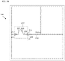
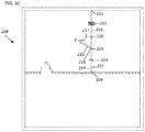
- the present example pertains to Figures 2A , 2B , 2C and 2D , which show schematic representations of an exemplary CAD model ( 200 ) at various stages during editing of the CAD model via an embodiment according to the present invention.
- the present example also pertains to example 1.
- the CAD model comprises a wall ( 204 ) comprising a door ( 205 , 206 , 207 ).
- the door comprises an opening arc ( 207 ), a door panel ( 205 ) and a wall end line ( 206 ).
- the door is represented via one or more curves.
- a user may draw ( Figure 2B ) a rectangular boundary ( 210 ) for selecting a region.
- the curves pertaining to the door are entirely enclosed in the region.
- the boundary intersects the wall ( 204 ) at four line segments ( 211 , 212 , 213 , 214 ) of the wall ( 204 ). Based on the four intersecting line segments, four reference points and corresponding outward pointing tangent reference directions are determined. In this particular example, the reference points are chosen on the entirely enclosed entities (entity magnetic feature).
- the user moves the cursor ( 2 ) to another wall ( 294 ) with equal thickness.
- This wall is represented in the CAD model by two line segments.
- the four reference points and corresponding reference directions can be mapped onto the two line segments of the other wall ( 294 ) near the cursor ( 2 ) position.
- Feature replication is suggested via the GUI, in particular a replication of the entities pertaining to the door (opening arc ( 217 ), door panel ( 215 ), wall end line ( 216 )), in mirrored form, as shown in Figure 2C .
- the suggested replication follows cursor movement.
- a first distance indicator ( 230 , 231 , 232 , 233 ) from a first reference point (at 230 ) to an outer end of a line segment of the wall is shown.
- the distance indicator thereby follows the reference direction associated with the first reference point.
- the distance indicator comprises two points ( 230 , 231 ), an indicator line ( 232 ) and a textbox ( 233 ) comprising a distance value, which is, as shown in Figure 2C , active for overwriting the distance value.
- a second distance indicator ( 220 , 221 , 222 , 223 ) from a second reference point (at 221 ) to an outer end of a line segment of the wall is also shown. The distance indicator thereby follows the reference direction associated with the second reference point.
- the distance indicator comprises two points ( 220 , 221 ), an indicator line ( 222 ) and a distance value ( 223 ).
- the user Via a TAB key on the keyboard, the user can toggle (switch between) activation of the distance values.
- a distance value e.g. entering a numerical value via a keyboard and pressing ENTER
- moving the cursor e.g. via a computer mouse
- confirming the position e.g. via clicking a computer mouse button
- the reference points are mapped onto candidate points on the line segments of the wall ( 294 ).
- the candidate points define outer parts (line segment 230 to 231 , and line segment 221 to 220 ) and an inner part (line segment 221 to 230 ) of each line segment of the wall ( 294 ). Insertion of the door trims the inner parts of the line segments of the wall ( 294 ). As the intersecting curves of the original wall ( 204 ) do not comprise inner parts, the trimmed portions of wall ( 294 ) are not replaced.
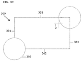
- the present example pertains to Figures 3A , 3B , 3C , 3D , 3E and 3F , which show schematic representations of an exemplary CAD model ( 300 ) at various stages during editing of the CAD model via an embodiment according to the present invention.
- the present example also pertains to example 1.
- the CAD model comprises a first line segment ( 301 ), a second line segment ( 302 ), a third line segment ( 303 ), a fourth line segment ( 304 ), and a circle ( 305 ).
- a user may draw ( Figure 3B ) a rectangular boundary ( 306 ) for selecting a region.
- the circle ( 305 ) is entirely enclosed in the region.
- the first and second line segments ( 301 , 302 ) intersect the boundary at points ( 307 ) and ( 308 ).
- two reference points ( 309 , 310 ) and corresponding outward pointing tangent reference directions are determined.
- the reference points are chosen on the entirely enclosed entities (entity magnetic feature).
- the user moves the cursor ( 2 ) to the junction of the third and fourth line segments ( 303 , 304 ).
- the two reference points and reference directions can be mapped onto these line segments near the cursor ( 2 ) position.
- Feature replication is suggested via the GUI, in particular of the circle, as shown in Figure 3C .
- the suggested circle ( 319 ) is inserted.
- the reference points are mapped onto candidate points on the third and fourth line segments.
- the candidate points define an outer part and an inner part of these line segments. Insertion of the door trims the inner parts of the third and fourth line segments ( Figure 3D ).
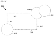
- a further replication of the feature may be suggested, as shown in Figure 3E . This may occur automatically upon confirming the previous suggestion, after reinstating via user input of the previous region selection, or after selecting a new region comprising one of the two circles ( 305 , 319 ).
- the two reference points and reference directions can be mapped onto the second circle ( 319 ) near the cursor ( 2 ) position.
- the reference directions are thereby tangent to the second circle ( 319 ) at corresponding candidate points ( 330 , 320 ) onto which the reference points are mapped.
- a first angle indicator ( 322 , 323 ) from a horizontal reference line ( 321 ) to a first candidate point ( 320 ) is shown.
- the first angle indicator comprises an arc ( 322 ) and an angle value ( 323 ).
- a second angle indicator ( 332 , 333 ) from the horizontal reference line ( 321 ) to a second candidate point ( 330 ) is also shown.
- the second angle indicator comprises an arc ( 332 ) and a textbox ( 333 ) comprising an angle value, which is, as shown in Figure 3E , active for overwriting the angle value. Via a TAB key on the keyboard, the user can toggle (switch between) activation of the angle values.
- an angle value e.g.
- the reference points are mapped onto candidate points ( 320 , 330 ) of the second circle ( 319 ).
- the candidate points define an outer part (from 330 to 320 : the part with the indication line for number 319 ) and an inner part (from 330 to 320 : the part with the indication lines for the arcs ( 322 , 332 ) of the angle indicators).
- Insertion of the suggested circle ( 349 ) trims the inner part of the second circle ( 319 ) ( Figure 3F ).
Landscapes
- Engineering & Computer Science (AREA)
- Physics & Mathematics (AREA)
- Geometry (AREA)
- Theoretical Computer Science (AREA)
- General Physics & Mathematics (AREA)
- Computer Hardware Design (AREA)
- General Engineering & Computer Science (AREA)
- Architecture (AREA)
- Evolutionary Computation (AREA)
- Mathematical Analysis (AREA)
- Mathematical Optimization (AREA)
- Pure & Applied Mathematics (AREA)
- Computational Mathematics (AREA)
- Human Computer Interaction (AREA)
- Computer Graphics (AREA)
- Software Systems (AREA)
- Structural Engineering (AREA)
- Civil Engineering (AREA)
- Processing Or Creating Images (AREA)
Priority Applications (2)
| Application Number | Priority Date | Filing Date | Title |
|---|---|---|---|
| EP19196814.8A EP3792809A1 (fr) | 2019-09-11 | 2019-09-11 | Réplication amélioré de caractéristiques dans un modèle cad |
| US17/017,827 US11960796B2 (en) | 2019-09-11 | 2020-09-11 | Feature replication in a CAD model |
Applications Claiming Priority (1)
| Application Number | Priority Date | Filing Date | Title |
|---|---|---|---|
| EP19196814.8A EP3792809A1 (fr) | 2019-09-11 | 2019-09-11 | Réplication amélioré de caractéristiques dans un modèle cad |
Publications (1)
| Publication Number | Publication Date |
|---|---|
| EP3792809A1 true EP3792809A1 (fr) | 2021-03-17 |
Family
ID=67928769
Family Applications (1)
| Application Number | Title | Priority Date | Filing Date |
|---|---|---|---|
| EP19196814.8A Pending EP3792809A1 (fr) | 2019-09-11 | 2019-09-11 | Réplication amélioré de caractéristiques dans un modèle cad |
Country Status (2)
| Country | Link |
|---|---|
| US (1) | US11960796B2 (fr) |
| EP (1) | EP3792809A1 (fr) |
Families Citing this family (2)
| Publication number | Priority date | Publication date | Assignee | Title |
|---|---|---|---|---|
| US20220253567A1 (en) * | 2021-02-05 | 2022-08-11 | Dassault Systemes Solidworks Corporation | Method for Suggesting Mates for a User Selected Modeled Component |
| CN113391819B (zh) * | 2021-06-23 | 2022-04-22 | 广东工业大学 | 一种基于边界表示的非流形cad软件之间的转换方法 |
Citations (4)
| Publication number | Priority date | Publication date | Assignee | Title |
|---|---|---|---|---|
| US5838328A (en) * | 1989-05-19 | 1998-11-17 | Hewlett-Packard Company | Method for generating graphical models and computer aided design system |
| US7079990B2 (en) | 2001-02-08 | 2006-07-18 | Solidworks Corporation | Automated connections of computer-aided design components |
| US20070174027A1 (en) * | 2006-01-26 | 2007-07-26 | Aleksey Moiseyev | Synchronized architectural and structural CAD models |
| US20170169135A1 (en) | 2015-12-11 | 2017-06-15 | Onshape Inc. | Replication of Components Through Geometric Element Matching |
Family Cites Families (2)
| Publication number | Priority date | Publication date | Assignee | Title |
|---|---|---|---|---|
| US8521486B2 (en) * | 2009-08-06 | 2013-08-27 | Paul B. Morton | Methods for searching for arrangements of shapes subject to boundary distance constraints among those shapes |
| US10341568B2 (en) * | 2016-10-10 | 2019-07-02 | Qualcomm Incorporated | User interface to assist three dimensional scanning of objects |
-
2019
- 2019-09-11 EP EP19196814.8A patent/EP3792809A1/fr active Pending
-
2020
- 2020-09-11 US US17/017,827 patent/US11960796B2/en active Active
Patent Citations (5)
| Publication number | Priority date | Publication date | Assignee | Title |
|---|---|---|---|---|
| US5838328A (en) * | 1989-05-19 | 1998-11-17 | Hewlett-Packard Company | Method for generating graphical models and computer aided design system |
| US7079990B2 (en) | 2001-02-08 | 2006-07-18 | Solidworks Corporation | Automated connections of computer-aided design components |
| US20070174027A1 (en) * | 2006-01-26 | 2007-07-26 | Aleksey Moiseyev | Synchronized architectural and structural CAD models |
| US20170169135A1 (en) | 2015-12-11 | 2017-06-15 | Onshape Inc. | Replication of Components Through Geometric Element Matching |
| WO2017098469A1 (fr) * | 2015-12-11 | 2017-06-15 | Onshape Inc. | Réplication de composants par le biais d'appariement d'éléments géométriques |
Also Published As
| Publication number | Publication date |
|---|---|
| US20210073431A1 (en) | 2021-03-11 |
| US11960796B2 (en) | 2024-04-16 |
Similar Documents
| Publication | Publication Date | Title |
|---|---|---|
| KR101955035B1 (ko) | 기하학적 3차원 모델링된 오브젝트를 디자인하는 방법 | |
| US8773425B2 (en) | Methods and apparatuses for proposing resolutions to conflicts in a CAD drawing with reflections | |
| US7969435B1 (en) | Method for modifying any modeled surface as a lofted surface | |
| KR101814811B1 (ko) | 3d 모델링된 객체의 워터마킹 | |
| JP3657771B2 (ja) | 三次元モデル作成装置 | |
| US11126759B2 (en) | Adding constraints between components of a computer-aided design (CAD) model | |
| CN110795796B (zh) | 设计表示机械结构的3d建模的对象 | |
| US11010499B2 (en) | User-selected dynamic dimensions in computer-aided design | |
| US11960796B2 (en) | Feature replication in a CAD model | |
| JPH07175843A (ja) | エッジの混合方法 | |
| EP3617913A1 (fr) | Création améliorée d'une vue éclatée d'un ensemble en cao | |
| CN110349262B (zh) | 一种基于bim的隧道超前地质预报三维建模方法及系统 | |
| US7107193B1 (en) | Defining parameters for a finite elements analysis calculation in a computer-assisted drafting program | |
| EP1594073A2 (fr) | Déformation d'une maquette CAO | |
| US11275870B2 (en) | Designing an assembly of parts in a three-dimensional scene | |
| JP2022171566A (ja) | 3dモデルのビュー/状態のリンク付けとその更新の伝播 | |
| US11734903B2 (en) | GUI for editing a CAD model | |
| US20020154149A1 (en) | System, method and computer program product for associative region generation and modification | |
| EP3035294B1 (fr) | Modèles 3d utilisant des marqueurs 3d afin d'indiquer des exigences d'ingénierie | |
| CN102831264A (zh) | 基于cad的地图信息转换方法 | |
| JP5644452B2 (ja) | 情報処理装置、その制御方法、及びプログラム | |
| Bendels et al. | Free-form modelling for surface inpainting | |
| JP4478493B2 (ja) | 図面作成プログラムおよび図面作成方法 | |
| Kalaskar et al. | Innovative PMI-Based Inspection Planning for Planar and Cylindrical Features | |
| BV et al. | COMSOL Multiphysics Reference Guide© COPYRIGHT 1998–2010 COMSOL AB. |
Legal Events
| Date | Code | Title | Description |
|---|---|---|---|
| PUAI | Public reference made under article 153(3) epc to a published international application that has entered the european phase |
Free format text: ORIGINAL CODE: 0009012 |
|
| STAA | Information on the status of an ep patent application or granted ep patent |
Free format text: STATUS: THE APPLICATION HAS BEEN PUBLISHED |
|
| AK | Designated contracting states |
Kind code of ref document: A1 Designated state(s): AL AT BE BG CH CY CZ DE DK EE ES FI FR GB GR HR HU IE IS IT LI LT LU LV MC MK MT NL NO PL PT RO RS SE SI SK SM TR |
|
| AX | Request for extension of the european patent |
Extension state: BA ME |
|
| STAA | Information on the status of an ep patent application or granted ep patent |
Free format text: STATUS: REQUEST FOR EXAMINATION WAS MADE |
|
| 17P | Request for examination filed |
Effective date: 20210713 |
|
| RBV | Designated contracting states (corrected) |
Designated state(s): AL AT BE BG CH CY CZ DE DK EE ES FI FR GB GR HR HU IE IS IT LI LT LU LV MC MK MT NL NO PL PT RO RS SE SI SK SM TR |
|
| STAA | Information on the status of an ep patent application or granted ep patent |
Free format text: STATUS: EXAMINATION IS IN PROGRESS |
|
| 17Q | First examination report despatched |
Effective date: 20230626 |
|
| 17Q | First examination report despatched |
Effective date: 20231211 |