EP3793043A1 - Verfahren und vorrichtung zur bereitstellung eines inkohärenten lichtfeldes und anwendungen davon, z. b. in einer optischen atomfalle - Google Patents
Verfahren und vorrichtung zur bereitstellung eines inkohärenten lichtfeldes und anwendungen davon, z. b. in einer optischen atomfalle Download PDFInfo
- Publication number
- EP3793043A1 EP3793043A1 EP19196945.0A EP19196945A EP3793043A1 EP 3793043 A1 EP3793043 A1 EP 3793043A1 EP 19196945 A EP19196945 A EP 19196945A EP 3793043 A1 EP3793043 A1 EP 3793043A1
- Authority
- EP
- European Patent Office
- Prior art keywords
- waveguide device
- light
- multimode waveguide
- optical
- light field
- Prior art date
- Legal status (The legal status is an assumption and is not a legal conclusion. Google has not performed a legal analysis and makes no representation as to the accuracy of the status listed.)
- Withdrawn
Links
Images
Classifications
-
- G—PHYSICS
- G21—NUCLEAR PHYSICS; NUCLEAR ENGINEERING
- G21K—HANDLING OF PARTICLES OR IONISING RADIATION NOT OTHERWISE PROVIDED FOR; IRRADIATION DEVICES; GAMMA RAY OR X-RAY MICROSCOPES
- G21K1/00—Arrangements for handling particles or ionising radiation, e.g. focusing or moderating
- G21K1/30—Arrangements for handling particles or ionising radiation, e.g. focusing or moderating for confining neutral particles or handling confined neutral particles, e.g. atom traps
-
- H—ELECTRICITY
- H01—ELECTRIC ELEMENTS
- H01S—DEVICES USING THE PROCESS OF LIGHT AMPLIFICATION BY STIMULATED EMISSION OF RADIATION [LASER] TO AMPLIFY OR GENERATE LIGHT; DEVICES USING STIMULATED EMISSION OF ELECTROMAGNETIC RADIATION IN WAVE RANGES OTHER THAN OPTICAL
- H01S3/00—Lasers, i.e. devices using stimulated emission of electromagnetic radiation in the infrared, visible or ultraviolet wave range
- H01S3/005—Optical devices external to the laser cavity, specially adapted for lasers, e.g. for homogenisation of the beam or for manipulating laser pulses, e.g. pulse shaping
-
- G—PHYSICS
- G02—OPTICS
- G02B—OPTICAL ELEMENTS, SYSTEMS OR APPARATUS
- G02B27/00—Optical systems or apparatus not provided for by any of the groups G02B1/00 - G02B26/00, G02B30/00
- G02B27/48—Laser speckle optics
-
- G—PHYSICS
- G02—OPTICS
- G02B—OPTICAL ELEMENTS, SYSTEMS OR APPARATUS
- G02B6/00—Light guides; Structural details of arrangements comprising light guides and other optical elements, e.g. couplings
- G02B6/10—Light guides; Structural details of arrangements comprising light guides and other optical elements, e.g. couplings of the optical waveguide type
- G02B6/14—Mode converters
-
- H—ELECTRICITY
- H01—ELECTRIC ELEMENTS
- H01S—DEVICES USING THE PROCESS OF LIGHT AMPLIFICATION BY STIMULATED EMISSION OF RADIATION [LASER] TO AMPLIFY OR GENERATE LIGHT; DEVICES USING STIMULATED EMISSION OF ELECTROMAGNETIC RADIATION IN WAVE RANGES OTHER THAN OPTICAL
- H01S2301/00—Functional characteristics
- H01S2301/20—Lasers with a special output beam profile or cross-section, e.g. non-Gaussian
-
- H—ELECTRICITY
- H01—ELECTRIC ELEMENTS
- H01S—DEVICES USING THE PROCESS OF LIGHT AMPLIFICATION BY STIMULATED EMISSION OF RADIATION [LASER] TO AMPLIFY OR GENERATE LIGHT; DEVICES USING STIMULATED EMISSION OF ELECTROMAGNETIC RADIATION IN WAVE RANGES OTHER THAN OPTICAL
- H01S3/00—Lasers, i.e. devices using stimulated emission of electromagnetic radiation in the infrared, visible or ultraviolet wave range
- H01S3/005—Optical devices external to the laser cavity, specially adapted for lasers, e.g. for homogenisation of the beam or for manipulating laser pulses, e.g. pulse shaping
- H01S3/0085—Modulating the output, i.e. the laser beam is modulated outside the laser cavity
-
- H—ELECTRICITY
- H01—ELECTRIC ELEMENTS
- H01S—DEVICES USING THE PROCESS OF LIGHT AMPLIFICATION BY STIMULATED EMISSION OF RADIATION [LASER] TO AMPLIFY OR GENERATE LIGHT; DEVICES USING STIMULATED EMISSION OF ELECTROMAGNETIC RADIATION IN WAVE RANGES OTHER THAN OPTICAL
- H01S3/00—Lasers, i.e. devices using stimulated emission of electromagnetic radiation in the infrared, visible or ultraviolet wave range
- H01S3/10—Controlling the intensity, frequency, phase, polarisation or direction of the emitted radiation, e.g. switching, gating, modulating or demodulating
- H01S3/13—Stabilisation of laser output parameters, e.g. frequency or amplitude
- H01S3/1306—Stabilisation of the amplitude
Definitions
- the invention relates to a light generation method for providing an incoherent light field and applications thereof.
- the light generation method is based on guiding a pulsed laser light beam through a multimode waveguide device, so that the incoherent light field is provided at an output of the waveguide device.
- the invention relates to a light source apparatus configured for providing an incoherent light field, and applications thereof.
- the invention also relates to an optical atom trap. Further applications of the invention are available in the fields of e. g. full-field imaging, speckle reduction, and/or image projection.
- spatial intensity noise is introduced in optical systems by partially reflecting optical surfaces and scattering particles (e.g. dust).
- the intensity noise results in image artefacts e. g. in full-field imaging applications. If the illuminating light is coherent, the artefacts are strongly enhanced since random high contrast interference patterns (speckles) emerge. Reducing temporal coherence thus reduces reflective noise and reducing spatial coherence reduces scattering noise.
- the complexity of the resonator configuration represents a restriction for routine applications in practice.
- Another approach uses the concept of temporal incoherence conversion by introducing propagation time delays in bulk optics, multi-core fibres or fibre bundles.
- a broadband light-emitting diode is used in combination with bulk optics in [3] for creating an incoherent light field for an optical atom trap.
- using the broadband source has disadvantages in terms of intensity noise and adjusting the light field relative to resonance frequencies of the atoms to be trapped.
- Incoherent light also can be generated by coupling an input light beam to a multimode optical fibre, exciting multiple modes guided in the optical fibre, superimposing the modes and thus providing the incoherent light field at an output of the optical fibre.
- Conventional techniques using the multimode optical fibre have been described e. g. in [4] to [7], wherein parameters of the input light beam and the optical fibre have been selected in dependency on the particular application conditions.
- the conventional approaches using multimode optical fibres have limitations in terms of bandwidth and intensity noise of the incoherent light field, as well as repetition frequency thereof as outlined in the following.
- a low-repetition rate picosecond (ps) laser source creates the input light beam to be coupled to the multimode optical fibre.
- This type of narrowband laser source is adapted for providing incoherent light in the fusion experiment.
- the low-repetition rate of some kHz it is not suitable for other applications, e. g. for illuminating a sample for short observation times in microscopy or for optically trapping atoms.
- a large fibre length of about 100 m is required.
- a femtosecond (fs) laser with a repetition frequency in the MHz range is used in [5] for providing incoherent light in optical coherence tomography (OCT).
- the input light beam to be coupled into the multimode optical fibre comprises fs laser pulse, i. e. it is spectrally far broader than the ps pulses used in [4].
- broadband pulses covering e. g. 50 nm ([5]) problems due to chromatic aberration effects may occur and adjusting the light field relative to resonance frequencies of trapped atoms in an optical atom trap is hindered.
- [6] also discloses an application of incoherent light in OCT, but uses a super-luminescent diode for creating the input light beam.
- the super-luminescent diode has a higher temporal noise compared with a laser source, thus restricting the application of this technique to OCT.
- an input light beam emitted from laser diodes is coupled to the multimode optical fibre for incoherent image projection in cinema projection displays.
- the laser diodes used in [7] suffer from the disadvantage of a limited temporal intensity and frequency stability.
- displayed images are magnified and not demagnified, so that controlling the degree of coherence is not considered in [7].
- the objective of the invention is to provide an improved light generation method for creating an incoherent light field, wherein the light generation method is capable of avoiding disadvantages of conventional techniques.
- the light generation method is to be suitable for an extended range of applications, e. g. in quantum technologies or image projection.
- the light generation method is to be capable of creating a light field with increased brightness, reduced spatial coherence and faster decorrelation, compared with conventional techniques.
- the light generation method is to be capable of creating a light field having an improved trapping efficiency in optical atom traps.
- the objective of the invention is to provide an improved light source apparatus configured for providing an incoherent light field wherein the light source apparatus is capable of avoiding disadvantages of conventional techniques.
- the light source apparatus is to be capable to provide a high-brightness, low-noise, spatially incoherent laser source with reduced complexity.
- the objective of the invention is to provide improved applications of incoherent light fields.
- the above objective is solved by a light generation method for providing an incoherent light field by the steps of creating a pulsed laser light beam of laser pulses (or: initial laser pulses), coupling the pulsed laser light beam to an input end of a multimode waveguide device and guiding the pulsed laser light beam to an output end of the multimode waveguide device, wherein the incoherent light field to be obtained is provided at the output end.
- the pulsed laser light beam is created with a pulse laser source device.
- the laser pulses provide a periodic sequence of temporally separated, pulse-shaped light fields.
- the laser pulses have a central wavelength, a pulse duration (represented by the spectral width of the pulses in the frequency domain) and a repetition rate.
- the multimode waveguide device comprises an optical waveguide, like e. g. an optical fibre, being capable of transmitting the pulsed laser light beam by total internal reflection.
- the multimode waveguide device has a cross-sectional dimension which is selected such that a plurality of guided spatial light modes, preferably at least 500 light modes, e. g. at least 1000 light modes can be accommodated by the multimode waveguide device.
- the initial laser pulses are coupled to the input end of the multimode waveguide device such that light modes among the plurality of light modes are excited. Light field portions of the laser pulses are guided by the excited light modes of the multimode waveguide device.
- the incoherent light field to be obtained (or: output light field) is created by the superposition of the light field portions, i.e. the excited light modes, at the output end of the multimode waveguide device. Due to different propagation times of the light modes within the multimode waveguide device, the light beam at the output end of the multimode waveguide device is no longer coherent like the initial laser pulses.
- a spatially dependent propagation delay is applied onto the spectrally broadband (i. e. temporally incoherent) but spatially coherent initial laser pulses.
- the waveguide device is designed such that the differential mode delay (differences in delay times of excited light modes within the waveguide device) are longer than the coherence time of the initial laser pulses. This leads to spatial decorrelation, resulting in a spatio-temporally incoherent light field.
- multimode waveguide device Since the multimode waveguide device is fully passive, potentially introduced noise by diffuser modulation is avoided and external global intensity stabilization can be easily implemented in contrast to complex lasers. In comparison to bulk optics, the necessary installation space at the output of the light source apparatus is also significantly reduced. As a further advantage, multimode waveguides, in particular fibres, also outperform waveguide bundles with respect to focussing ability since spatial modes are more loosely packed.
- Coupling the pulsed laser light beam to the input end of the multimode waveguide device comprises irradiating, preferably focussed irradiating, the input end with the initial laser pulses.
- Perpendicular incoupling comprises irradiating the input end with a direction of incidence parallel to the axial direction of the multimode waveguide device.
- oblique incoupling the laser pulses is possible.
- the input end of the multimode waveguide device comprises at least one end facet through which the laser pulses are transmitted into the waveguide.
- the initial laser pulses are created with a repetition rate equal to or above 100 kHz, preferably equal to or above 500 kHz, e. g. 1 MHz or higher.
- the repetition rate is substantially increased, thus providing an increased intensity of the output light field, resulting in advantages e. g. in image projection or atom trapping applications.
- the repetition rate is far above the trap frequencies, so that the trapping efficiency is substantially increased.
- An upper limit of the repetition rate should be significantly below the spectral bandwidth of about 100 GHz at 0.1 nm, while technical possibilities limit the range typically to about 1 GHz.
- the initial laser pulses are created with a relative spectral width of 10 -4 to 10 -2 .
- the relative spectral width is the spectral width of the laser pulses divided by the central wavelength thereof.
- the spectral width of the laser pulses preferably is in a range of 0.1 nm to 10 nm.
- the spectral width is equal to or below 10 nm, e. g. equal to or below 6 nm or even equal to or below 1 nm.
- the spectral width of the initial laser pulses is increased, thus allowing a reduction of the length of the multimode waveguide device.
- the spectral width of the initial laser pulses is substantially reduced, thus facilitating an adjustment of the incoherent light relative to resonance frequencies of atoms in an optical atom trap.
- the initial laser pulses preferably have a pulse duration in a range from 100 fs, e. g. 200 fs or 300 fs, to 10 ps, e. g. 5 ps or 3 ps.
- the interval of relative spectral width used according to the invention has been found by the inventors by the following considerations. With a relative spectral width below 10 -4 , the coherence time would be increased such that impractical waveguide lengths would be required. With a relative spectral width above 10 -2 , disadvantages for the optical set-up would arise and chromatic aberration would be deteriorating for practical applications.
- a light source apparatus configured for providing an incoherent light field.
- the light source apparatus comprises a pulse laser source device for emitting a pulsed laser light beam of laser pulses, and a multimode waveguide device having an input end and an output end and being arranged for receiving the pulsed laser light beam at the input end and guiding the pulsed laser light beam by total internal reflection.
- the multimode waveguide device is adapted for providing the incoherent light field at the output end thereof.
- the pulse laser source device is configured for creating the laser pulses with a repetition rate equal to or above 100 kHz and a relative spectral width of 10 -4 to 10 -2 , as explained above.
- the light source apparatus is adapted for providing the incoherent light field with the method according to the above first general aspect of the invention.
- the invention employs separation of light generation and spatial decorrelation. This enables high flexibility in varying required coherence properties, in particular controlling the degree of coherence, spectral widths and intensity properties, and minimizes realignment efforts.
- the invention provides a high-brightness, low-noise, spatially incoherent laser source, enabling speckle-free, high intensity, low temporal intensity noise, and efficient illumination, imaging and/or atom trapping applications.
- optical waveguide with a suitable differential mode delay can be employed as the multimode waveguide device, like optical fibres or monolithic waveguides on substrates.
- optical fibres with a circular cross-sectional shape may have advantages in terms of large number of variants of commercially available fibres.
- the multimode waveguide device has a circularly asymmetrical cross-sectional shape.
- This shape provides advantages in terms of a high coupling efficiency with perpendicular incoupling to the waveguide device.
- the use of the circularly asymmetrical shape minimizes the modal overlap with the waveguide-launched Gaussian profile. Thus the dependency on launching conditions is reduced and fluctuations due to coupling instabilities are avoided.
- the multimode waveguide device comprises a square core optical fibre.
- square core optical fibres are commercially available from applications in astronomy.
- the square-core geometry has advantages due to insensitivity to fibre coupling conditions, again minimizing temporal intensity fluctuations and also leading to a uniform output intensity distribution. This additionally allows under-filling launch conditions without mode scrambiers, significantly increasing transmission efficiency.
- choosing an appropriate core geometry allows matching the image format (e.g. square core for quadratic image).
- the multimode waveguide device has a longitudinal length of at least 80 cm, in particular at least 300 cm. These preferred values are used e. g. with an embodiment including 1000 incoherent waveguide modes at 10 -2 spectral width and a numerical aperture (NA) of 0.48 NA of the waveguide input end. On the other hand, depending on the spectral width, the length might significantly exceed 20 m, which is technologically unproblematic, and typically is below 1 km.
- the multimode waveguide device preferably has a numerical aperture equal to or above 0.2, e. g. 0.22 or higher, or in particular equal to or above 0.3, e. g. 0.39 or higher.
- laser pulses are generated with a mode-locked pulse laser, particularly preferred with a mode-locked femtosecond laser, further advantages relating to brightness and temporal stability are obtained.
- Laser pulses created with the mode-locked pulse laser are described in frequency domain as frequency combs.
- the frequency comb properties additionally allow for low intensity noise operation (below its repetition rate) not reached with complex lasers or (super-luminescent) diodes as light sources, enabling in particular high-power and high-speed imaging applications.
- the light generation method includes an active stabilization of the output power of the incoherent light field, in particular the step of stabilizing the output power of the incoherent light field at the output end of the multimode waveguide device by employing a feedback stabilization loop device.
- the light source apparatus further comprises a feedback stabilization loop device arranged for stabilizing the output power of the incoherent light field at the output end of the multimode waveguide device.
- Active stabilization comprises detecting the power of the initial laser pulses or preferably the output light field power and controlling the power of the initial laser pulse coupled into the waveguide device in dependency of the detected power of the initial laser pulses or output light field power.
- the power of the initial laser pulses is controlled by direct control of the pulse laser source device or preferably by controlling an acousto-optical modulator arranged between the pulse laser source device and the input end of the waveguide device.
- controlling in dependency on the output light field power allows for stabilization of noise introduced between the pulse laser source device and the output end of the multimode fibre.
- the stabilization of only the pulse laser source device is possible.
- the above objective is solved by an atom trapping method wherein an optical atom trap is created with an incoherent light field provided with the light generation method according to the above first general aspect of the invention.
- the optical atom trap is created for trapping atoms in an atom trap chamber device by coupling the incoherent light field to the atom trap chamber device.
- the optical atom trap is designed with a trap frequency and the atoms have multiple resonance frequencies.
- the laser pulses for providing the incoherent light field are created such that the repetition rate is above the trap frequency and the spectral width is below a spectral range between the resonance frequencies. In other words, all frequency components of the incoherent light are to be sufficiently detuned from atomic resonances.
- the spectral bandwidth of the laser pulses used for creating the incoherent light is selected to be far below the spectral range between resonances.
- an optical atom trap apparatus comprising the light source apparatus according to the above second general aspect of the invention and an atom trap chamber device configured for receiving the incoherent light field and creating an optical atom trap for trapping atoms having multiple resonance frequencies.
- the atom trap chamber device comprises in particular an evacuable chamber with transparent windows and a cooling unit, a supply system for introducing atoms into the chamber, a magnet field device, monitoring devices and control devices.
- the optical atom trap is configured for an operation at a predetermined trap frequency.
- the pulse laser source device of the light source apparatus is configured for creating the laser pulses such that the repetition rate is above the trap frequency and the spectral width is below a spectral range between the resonance frequencies.
- Preferred applications of the inventive generation of incoherent light include creating an optical atom trap, illuminating a sample for microscopic imaging, creating an optical tweezer, general applications of speckle reduction, in lithography applications and/or image projection, in particular with a digital micro-mirror device.
- the waveguide device comprises an optical fibre
- the pulse laser source device comprises a fs pulse laser and the power of the output light field is actively stabilized using a control loop.
- the implementation of the invention is not restricted to these features.
- another waveguide device or pulse laser source device can be used and/or the active stabilization can be omitted.
- Further optical components can be added.
- the pulse laser source device can be provided with a mode filter, like a single mode fibre.
- Exemplary reference is made to an optical atom trap apparatus, which is operated with the incoherent light provided according to the invention. Details of operating the optical atom trap apparatus are not described as they are known per se from conventional techniques.
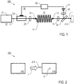
- an embodiment of the light source apparatus 100 for creating incoherent light 1 comprises a waveguide device 10, including an optical fibre 11 with an input end 12 and an output end 13.
- the optical fibre 11 is a square-core (or other circularly asymmetrical) multimode optical step-index fibre, e. g. with a core dimension of 150 ⁇ m ⁇ 150 ⁇ m and a length of 300 cm, made of e. g. fused silica.
- Each of the input and output ends 12, 13 comprise flat smooth end facets.
- the input end 12 can be provided with an anti-reflective coating (not shown).
- the optical fibre 11 can be arranged with a straight or curved shape, e. g. in a protective container.
- the light source apparatus 100 has a pulse laser source device 20, which comprises a mode-locked femtosecond pulse laser 21, e. g. a frequency-doubled Er laser or a Ti-sapphire laser.
- the fs pulse laser 21 generates spatially coherent light providing a pulsed laser light beam 2 of laser pulses to be coupled via focussing optics 22 (coupling lens in) to the optical fibre 11.
- the pulsed laser light beam 2 has a repetition frequency of 80 MHz, a central wavelength of 700 nm to 800 nm, a spectral width of 5 nm and an average power of 0.2 W.
- the mode-locked femtosecond laser 21 provides spectral widths of multiple nanometres which allows fast decorrelation. Its comb-like spectrum gives rise to well-defined beating frequencies in the range of hundreds of MHz such that the intensity noise spectrum (apart from these beating frequencies) is similarly low as that of single-mode lasers.
- the optical fibre 11 provides a delaying element with different propagation times for each of the fibre modes.
- straightly propagating rays arrive at the output end 13 earlier than rays travelling at an angle since the distance covered is longer.
- the different rays correspond to different spatial modes. Since the spatial modes have distinct intensity profiles, the spatial decorrelation is achieved, so that the incoherent light field 1 is output at the output end 13 of the optical fibre 11.
- the fibre output end 13 acts as a secondary, incoherent light source, and is imaged with an output optics 14 (coupling lens out) onto an object to be illuminated, e. g. into an atom trap chamber device 210 (see Figure 2 ) or another optical system, like a microscopic imaging device or a projector.
- the light source apparatus 100 is provided with a feedback stabilization loop device 30, comprising a photodiode 31, a feedback control unit 32 and an acousto-optical modulator (AOM) 33.
- a portion of the output light field 1 is deflected with a beam sampler 34, e. g. a semi-transmissive plate, and a focussing lens 35 to the photodiode 31.
- the feedback control unit 32 drives the AOM 33, such that possible temporal power changes are compensated and the output light field 1 has a constant power.
- the AOM 33 By driving the AOM 33, the transmission of the pulsed laser light beam 2 is modified.
- a mode filter (not shown) is arranged between the femtosecond pulse laser 21 and the AOM 33.
- a feedback-based intensity stabilization may be installed and residual temporal noise of the femtosecond pulse laser 21 is minimized.
- an embodiment of an optical atom trap apparatus 200 comprises the light source apparatus 100 of Figure 1 and a schematically illustrated atom trap chamber device 210.
- an atom trap 3 is formed.
- the atom trap chamber device 210 has a configuration and is operated as known per se in prior art, e. g. as described in [8].
- a digital micro-mirror device 211 (arrangement schematically shown) can be provided for shaping the light field and selecting a shape of the atom trap 3.
Landscapes
- Physics & Mathematics (AREA)
- Electromagnetism (AREA)
- Engineering & Computer Science (AREA)
- Plasma & Fusion (AREA)
- Optics & Photonics (AREA)
- Spectroscopy & Molecular Physics (AREA)
- General Engineering & Computer Science (AREA)
- High Energy & Nuclear Physics (AREA)
- Lasers (AREA)
Priority Applications (4)
| Application Number | Priority Date | Filing Date | Title |
|---|---|---|---|
| EP19196945.0A EP3793043A1 (de) | 2019-09-12 | 2019-09-12 | Verfahren und vorrichtung zur bereitstellung eines inkohärenten lichtfeldes und anwendungen davon, z. b. in einer optischen atomfalle |
| US17/642,514 US12131834B2 (en) | 2019-09-12 | 2020-09-10 | Method of creating an optical atom trap and atom trap apparatus, employing an incoherent light field |
| PCT/EP2020/075346 WO2021048287A1 (en) | 2019-09-12 | 2020-09-10 | Method of creating an optical atom trap and atom trap apparatus, employing an incoherent light field |
| EP20768046.3A EP4029093A1 (de) | 2019-09-12 | 2020-09-10 | Verfahren zur erzeugung einer optischen atomfalle und atomfallengerät mit einem inkohärenten lichtfeld |
Applications Claiming Priority (1)
| Application Number | Priority Date | Filing Date | Title |
|---|---|---|---|
| EP19196945.0A EP3793043A1 (de) | 2019-09-12 | 2019-09-12 | Verfahren und vorrichtung zur bereitstellung eines inkohärenten lichtfeldes und anwendungen davon, z. b. in einer optischen atomfalle |
Publications (1)
| Publication Number | Publication Date |
|---|---|
| EP3793043A1 true EP3793043A1 (de) | 2021-03-17 |
Family
ID=67953633
Family Applications (2)
| Application Number | Title | Priority Date | Filing Date |
|---|---|---|---|
| EP19196945.0A Withdrawn EP3793043A1 (de) | 2019-09-12 | 2019-09-12 | Verfahren und vorrichtung zur bereitstellung eines inkohärenten lichtfeldes und anwendungen davon, z. b. in einer optischen atomfalle |
| EP20768046.3A Pending EP4029093A1 (de) | 2019-09-12 | 2020-09-10 | Verfahren zur erzeugung einer optischen atomfalle und atomfallengerät mit einem inkohärenten lichtfeld |
Family Applications After (1)
| Application Number | Title | Priority Date | Filing Date |
|---|---|---|---|
| EP20768046.3A Pending EP4029093A1 (de) | 2019-09-12 | 2020-09-10 | Verfahren zur erzeugung einer optischen atomfalle und atomfallengerät mit einem inkohärenten lichtfeld |
Country Status (3)
| Country | Link |
|---|---|
| US (1) | US12131834B2 (de) |
| EP (2) | EP3793043A1 (de) |
| WO (1) | WO2021048287A1 (de) |
Cited By (1)
| Publication number | Priority date | Publication date | Assignee | Title |
|---|---|---|---|---|
| CN115132395A (zh) * | 2022-08-30 | 2022-09-30 | 山西大学 | 一种基于铯单原子魔术光镊的单光子源产生装置及方法 |
Families Citing this family (7)
| Publication number | Priority date | Publication date | Assignee | Title |
|---|---|---|---|---|
| US11995512B2 (en) | 2018-11-13 | 2024-05-28 | Atom Computing Inc. | Scalable neutral atom based quantum computing |
| US11580435B2 (en) | 2018-11-13 | 2023-02-14 | Atom Computing Inc. | Scalable neutral atom based quantum computing |
| US10504033B1 (en) | 2018-11-13 | 2019-12-10 | Atom Computing Inc. | Scalable neutral atom based quantum computing |
| JP7708774B2 (ja) | 2020-03-02 | 2025-07-15 | アトム コンピューティング インク. | スケーラブルな中性原子ベースの量子コンピューティング |
| KR102887206B1 (ko) | 2020-03-02 | 2025-11-17 | 아톰 컴퓨팅 인크. | 확장 가능한 중성 원자 기반 양자 컴퓨팅 |
| CA3219185A1 (en) * | 2021-05-17 | 2022-12-08 | Brian Lester | Scalable neutral atom based quantum computing |
| EP4526813A4 (de) | 2022-05-19 | 2026-05-06 | Atom Computing Inc | Vorrichtungen und verfahren für hohlraumbasierte berechnung |
Citations (2)
| Publication number | Priority date | Publication date | Assignee | Title |
|---|---|---|---|---|
| US20140071406A1 (en) * | 2012-01-02 | 2014-03-13 | Jgm Associates, Inc. | Low-speckle Light Sources and Displays Employing Multimode Optical Fiber |
| US9413372B1 (en) * | 2015-07-30 | 2016-08-09 | The Aerospace Corporation | Systems and methods for converting radio frequency signals into the digital domain using multi-mode optics |
Family Cites Families (4)
| Publication number | Priority date | Publication date | Assignee | Title |
|---|---|---|---|---|
| US7705990B2 (en) * | 2006-08-04 | 2010-04-27 | Agilent Technologies, Inc. | Optical sources for SPR applications |
| US10656427B2 (en) * | 2016-09-29 | 2020-05-19 | Nlight, Inc. | Multicore fiber-coupled optical probing techniques |
| JP6875680B2 (ja) | 2017-04-10 | 2021-05-26 | 浜松ホトニクス株式会社 | 量子シミュレータおよび量子シミュレーション方法 |
| FR3074371B1 (fr) * | 2017-11-24 | 2021-05-14 | Ixblue | Dispositif et procede d'interaction entre un faisceau laser agile et une transition energetique hyperfine d'une espece chimique |
-
2019
- 2019-09-12 EP EP19196945.0A patent/EP3793043A1/de not_active Withdrawn
-
2020
- 2020-09-10 US US17/642,514 patent/US12131834B2/en active Active
- 2020-09-10 EP EP20768046.3A patent/EP4029093A1/de active Pending
- 2020-09-10 WO PCT/EP2020/075346 patent/WO2021048287A1/en not_active Ceased
Patent Citations (3)
| Publication number | Priority date | Publication date | Assignee | Title |
|---|---|---|---|---|
| US20140071406A1 (en) * | 2012-01-02 | 2014-03-13 | Jgm Associates, Inc. | Low-speckle Light Sources and Displays Employing Multimode Optical Fiber |
| US9046697B2 (en) | 2012-01-02 | 2015-06-02 | Jgm Associates, Inc. | Low-speckle light sources and displays employing multimode optical fiber |
| US9413372B1 (en) * | 2015-07-30 | 2016-08-09 | The Aerospace Corporation | Systems and methods for converting radio frequency signals into the digital domain using multi-mode optics |
Non-Patent Citations (9)
| Title |
|---|
| A.-H. DHALLA ET AL.: "Crosstalk rejection in parallel optical coherence tomography using spatially incoherent illumination with partially coherent sources", OPTICS LETTERS, vol. 35.13, 2010, pages 2305 - 2307, XP001555640, doi:10.1364/OL.35.002305 |
| H. CAO ET AL.: "Complex lasers with controllable coherence", NATURE REVIEWS PHYSICS, vol. 1, 2019, pages 156 - 168 |
| H. NAKANO ET AL.: "Partially coherent light generated by using single and multimode optical fibers in a high-power Nd: glass laser system", APPLIED PHYSICS LETTERS, vol. 63.5, 1993, pages 580 - 582, XP000388100, doi:10.1063/1.109955 |
| J. KIM ET AL.: "Speckle reduction in OCT with multimode source fiber'' in ''Optical Fibers and Sensors for Medical Applications IV", INTERNATIONAL SOCIETY FOR OPTICS AND PHOTONICS, vol. 5317, 2004 |
| JAYICH A M ET AL: "Direct frequency comb laser cooling and trapping", ARXIV.ORG, CORNELL UNIVERSITY LIBRARY, 201 OLIN LIBRARY CORNELL UNIVERSITY ITHACA, NY 14853, 26 March 2016 (2016-03-26), XP080692107 * |
| N. SANTIC ET AL: "Cooling of atoms using an optical frequency comb", SCIENTIFIC REPORTS, vol. 9, no. 1, 21 February 2019 (2019-02-21), XP055688326, DOI: 10.1038/s41598-018-38319-3 * |
| R. GRIMM ET AL.: "Optical dipole traps for neutral atoms", ADVANCES IN ATOMIC, MOLECULAR, AND OPTICAL PHYSICS, vol. 42, 2000, pages 95 - 170 |
| R. MA: "Dissertation", 2014, HARVARD UNIVERSITY, article "Engineered potentials and dynamics of ultracold quantum gases under the microscope" |
| T. IWAI ET AL.: "Speckle reduction in coherent information processing", PROCEEDINGS OF THE IEEE, vol. 84, 1996, pages 765 - 781, XP000591804, doi:10.1109/5.488745 |
Cited By (2)
| Publication number | Priority date | Publication date | Assignee | Title |
|---|---|---|---|---|
| CN115132395A (zh) * | 2022-08-30 | 2022-09-30 | 山西大学 | 一种基于铯单原子魔术光镊的单光子源产生装置及方法 |
| CN115132395B (zh) * | 2022-08-30 | 2022-11-11 | 山西大学 | 一种基于铯单原子魔术光镊的单光子源产生装置及方法 |
Also Published As
| Publication number | Publication date |
|---|---|
| WO2021048287A1 (en) | 2021-03-18 |
| US20220344069A1 (en) | 2022-10-27 |
| EP4029093A1 (de) | 2022-07-20 |
| US12131834B2 (en) | 2024-10-29 |
Similar Documents
| Publication | Publication Date | Title |
|---|---|---|
| US12131834B2 (en) | Method of creating an optical atom trap and atom trap apparatus, employing an incoherent light field | |
| US20130077147A1 (en) | Method for producing a partially coherent beam with fast pattern update rates | |
| US12088056B2 (en) | Laser light source and laser projector with laser light source | |
| US7292749B2 (en) | System for electromagnetic field conversion | |
| KR100592858B1 (ko) | 조명 방법 및 조명 장치 | |
| US7098447B2 (en) | Light source for the illumination of microscopic specimens and scanning microscope system | |
| US20180269648A1 (en) | Generation of arbitrary time-space distribution phase-coherent discretized laser beams | |
| WO1996041404A1 (en) | Fiber optic laser system and associated lasing method | |
| KR19990088320A (ko) | 광코히런스저감방법과그장치,조명방법과그시스템,및광섬유다발 | |
| JP4353992B2 (ja) | 照明用光源装置および画像表示装置 | |
| CN110168423B (zh) | 照明装置和用于在显微镜中照明的方法和显微镜 | |
| JP4260851B2 (ja) | 照明用光源装置および画像表示装置 | |
| US7532651B2 (en) | Illumination system for optical modulators | |
| EP3920346B1 (de) | Selbstinjektionsverriegelter stimulierter brillouin-streuungslaser | |
| US6554464B1 (en) | Apparatus for and method of reducing or eliminating interference effects in a light tunnel illuminator | |
| JP2006510886A (ja) | 試料の光学的検査および/または光学的加工のための方法および配置 | |
| US6934086B2 (en) | Optical component and compact wavelength locking arrangement including such a component | |
| JP7301130B2 (ja) | マルチプレーン光変換デバイスを含む光放射を処理するためのデバイス | |
| JP6763121B2 (ja) | レーザ装置 | |
| Kivshar | Engineered metaoptics forge new nonlinear devices | |
| JP5007057B2 (ja) | 電子ビーム発生装置 | |
| KR102923772B1 (ko) | 포토닉스 구조체를 이용한 양자얽힘 광자 쌍 생성 장치 및 이를 이용한 양자얽힘 광자 쌍 생성 방법 | |
| EP4664693A1 (de) | Lichtquellenvorrichtung | |
| US20250068002A1 (en) | Multi-pulse light source and multi-pulse light generation method | |
| Stutz et al. | Optical feedback stabilization of a frequency comb generated by a self-mode-locked quantum dot laser emitting at 1255 nm |
Legal Events
| Date | Code | Title | Description |
|---|---|---|---|
| PUAI | Public reference made under article 153(3) epc to a published international application that has entered the european phase |
Free format text: ORIGINAL CODE: 0009012 |
|
| STAA | Information on the status of an ep patent application or granted ep patent |
Free format text: STATUS: THE APPLICATION HAS BEEN PUBLISHED |
|
| AK | Designated contracting states |
Kind code of ref document: A1 Designated state(s): AL AT BE BG CH CY CZ DE DK EE ES FI FR GB GR HR HU IE IS IT LI LT LU LV MC MK MT NL NO PL PT RO RS SE SI SK SM TR |
|
| AX | Request for extension of the european patent |
Extension state: BA ME |
|
| STAA | Information on the status of an ep patent application or granted ep patent |
Free format text: STATUS: THE APPLICATION IS DEEMED TO BE WITHDRAWN |
|
| 18D | Application deemed to be withdrawn |
Effective date: 20210918 |