EP3793088A2 - Elastische oberflächenwellen verwendende sensorvorrichtung geeignet zur fernabfrage - Google Patents
Elastische oberflächenwellen verwendende sensorvorrichtung geeignet zur fernabfrage Download PDFInfo
- Publication number
- EP3793088A2 EP3793088A2 EP20196942.5A EP20196942A EP3793088A2 EP 3793088 A2 EP3793088 A2 EP 3793088A2 EP 20196942 A EP20196942 A EP 20196942A EP 3793088 A2 EP3793088 A2 EP 3793088A2
- Authority
- EP
- European Patent Office
- Prior art keywords
- transducer
- electrodes
- bragg
- resonator
- frequency
- Prior art date
- Legal status (The legal status is an assumption and is not a legal conclusion. Google has not performed a legal analysis and makes no representation as to the accuracy of the status listed.)
- Withdrawn
Links
- 238000010897 surface acoustic wave method Methods 0.000 title description 4
- 210000001520 comb Anatomy 0.000 claims abstract description 4
- 230000005284 excitation Effects 0.000 claims description 28
- 239000000758 substrate Substances 0.000 claims description 23
- 230000003595 spectral effect Effects 0.000 claims description 22
- 229910052697 platinum Inorganic materials 0.000 claims description 16
- 239000000463 material Substances 0.000 claims description 15
- 239000010453 quartz Substances 0.000 claims description 11
- VYPSYNLAJGMNEJ-UHFFFAOYSA-N silicon dioxide Inorganic materials O=[Si]=O VYPSYNLAJGMNEJ-UHFFFAOYSA-N 0.000 claims description 11
- 230000001747 exhibiting effect Effects 0.000 claims description 8
- 230000008878 coupling Effects 0.000 claims description 7
- 238000010168 coupling process Methods 0.000 claims description 7
- 238000005859 coupling reaction Methods 0.000 claims description 7
- 238000007667 floating Methods 0.000 claims description 7
- 229910052782 aluminium Inorganic materials 0.000 claims description 4
- 238000009529 body temperature measurement Methods 0.000 claims description 4
- 229910052802 copper Inorganic materials 0.000 claims description 4
- 230000005855 radiation Effects 0.000 claims description 4
- 229910052719 titanium Inorganic materials 0.000 claims description 4
- 230000007423 decrease Effects 0.000 claims description 3
- 230000010349 pulsation Effects 0.000 claims description 3
- 229910052710 silicon Inorganic materials 0.000 claims description 3
- -1 LiBa4 O7 Inorganic materials 0.000 claims description 2
- 241000490025 Schefflera digitata Species 0.000 claims description 2
- 239000000956 alloy Substances 0.000 claims description 2
- 229910045601 alloy Inorganic materials 0.000 claims description 2
- 229910052804 chromium Inorganic materials 0.000 claims description 2
- 150000001875 compounds Chemical class 0.000 claims description 2
- 239000010432 diamond Substances 0.000 claims description 2
- 229910003460 diamond Inorganic materials 0.000 claims description 2
- 239000002223 garnet Substances 0.000 claims description 2
- 239000011521 glass Substances 0.000 claims description 2
- 229910052741 iridium Inorganic materials 0.000 claims description 2
- 229910052750 molybdenum Inorganic materials 0.000 claims description 2
- 229910052759 nickel Inorganic materials 0.000 claims description 2
- 229910052763 palladium Inorganic materials 0.000 claims description 2
- 229910052594 sapphire Inorganic materials 0.000 claims description 2
- 239000010980 sapphire Substances 0.000 claims description 2
- 229910052709 silver Inorganic materials 0.000 claims description 2
- 239000010409 thin film Substances 0.000 claims description 2
- 229910052721 tungsten Inorganic materials 0.000 claims description 2
- 229910052726 zirconium Inorganic materials 0.000 claims description 2
- 229910003334 KNbO3 Inorganic materials 0.000 claims 1
- 229910003327 LiNbO3 Inorganic materials 0.000 claims 1
- 229910012463 LiTaO3 Inorganic materials 0.000 claims 1
- 229910000154 gallium phosphate Inorganic materials 0.000 claims 1
- 239000010703 silicon Substances 0.000 claims 1
- 230000001360 synchronised effect Effects 0.000 abstract description 6
- 230000004044 response Effects 0.000 description 42
- BASFCYQUMIYNBI-UHFFFAOYSA-N platinum Substances [Pt] BASFCYQUMIYNBI-UHFFFAOYSA-N 0.000 description 38
- 239000011159 matrix material Substances 0.000 description 14
- 230000000737 periodic effect Effects 0.000 description 11
- 238000001465 metallisation Methods 0.000 description 10
- 238000004364 calculation method Methods 0.000 description 8
- 230000000875 corresponding effect Effects 0.000 description 8
- 230000008859 change Effects 0.000 description 7
- 230000000694 effects Effects 0.000 description 7
- 230000008901 benefit Effects 0.000 description 5
- 238000013461 design Methods 0.000 description 5
- 230000026683 transduction Effects 0.000 description 5
- 238000010361 transduction Methods 0.000 description 5
- 238000004458 analytical method Methods 0.000 description 4
- 230000005540 biological transmission Effects 0.000 description 4
- 238000005259 measurement Methods 0.000 description 4
- 238000001514 detection method Methods 0.000 description 3
- 239000010410 layer Substances 0.000 description 3
- 238000005457 optimization Methods 0.000 description 3
- 230000001902 propagating effect Effects 0.000 description 3
- 238000002310 reflectometry Methods 0.000 description 3
- 238000004088 simulation Methods 0.000 description 3
- 229920000535 Tan II Polymers 0.000 description 2
- 238000013459 approach Methods 0.000 description 2
- 239000013078 crystal Substances 0.000 description 2
- 238000005520 cutting process Methods 0.000 description 2
- 238000005516 engineering process Methods 0.000 description 2
- 238000003780 insertion Methods 0.000 description 2
- 230000037431 insertion Effects 0.000 description 2
- 238000004519 manufacturing process Methods 0.000 description 2
- 238000013507 mapping Methods 0.000 description 2
- 238000000034 method Methods 0.000 description 2
- 230000003071 parasitic effect Effects 0.000 description 2
- 238000012545 processing Methods 0.000 description 2
- WSMQKESQZFQMFW-UHFFFAOYSA-N 5-methyl-pyrazole-3-carboxylic acid Chemical compound CC1=CC(C(O)=O)=NN1 WSMQKESQZFQMFW-UHFFFAOYSA-N 0.000 description 1
- 102100037676 CCAAT/enhancer-binding protein zeta Human genes 0.000 description 1
- 102100028892 Cardiotrophin-1 Human genes 0.000 description 1
- 208000031361 Hiccup Diseases 0.000 description 1
- 101000880588 Homo sapiens CCAAT/enhancer-binding protein zeta Proteins 0.000 description 1
- 101000916283 Homo sapiens Cardiotrophin-1 Proteins 0.000 description 1
- 229910013641 LiNbO 3 Inorganic materials 0.000 description 1
- 230000001133 acceleration Effects 0.000 description 1
- 238000000137 annealing Methods 0.000 description 1
- 238000003491 array Methods 0.000 description 1
- 239000000470 constituent Substances 0.000 description 1
- 230000002596 correlated effect Effects 0.000 description 1
- 230000001808 coupling effect Effects 0.000 description 1
- 238000000151 deposition Methods 0.000 description 1
- 230000008021 deposition Effects 0.000 description 1
- 238000011161 development Methods 0.000 description 1
- 238000010494 dissociation reaction Methods 0.000 description 1
- 230000005593 dissociations Effects 0.000 description 1
- 238000009826 distribution Methods 0.000 description 1
- 230000007613 environmental effect Effects 0.000 description 1
- 238000005530 etching Methods 0.000 description 1
- 238000009472 formulation Methods 0.000 description 1
- 238000012423 maintenance Methods 0.000 description 1
- 229910052751 metal Inorganic materials 0.000 description 1
- 239000002184 metal Substances 0.000 description 1
- 239000000203 mixture Substances 0.000 description 1
- 238000012986 modification Methods 0.000 description 1
- 230000004048 modification Effects 0.000 description 1
- 238000012544 monitoring process Methods 0.000 description 1
- 230000010355 oscillation Effects 0.000 description 1
- 244000045947 parasite Species 0.000 description 1
- 238000000206 photolithography Methods 0.000 description 1
- 230000010287 polarization Effects 0.000 description 1
- 230000000717 retained effect Effects 0.000 description 1
- 230000002441 reversible effect Effects 0.000 description 1
- 238000012552 review Methods 0.000 description 1
- 230000035945 sensitivity Effects 0.000 description 1
- HBMJWWWQQXIZIP-UHFFFAOYSA-N silicon carbide Chemical compound [Si+]#[C-] HBMJWWWQQXIZIP-UHFFFAOYSA-N 0.000 description 1
- 229910010271 silicon carbide Inorganic materials 0.000 description 1
- 239000002356 single layer Substances 0.000 description 1
- 238000012360 testing method Methods 0.000 description 1
- 230000008542 thermal sensitivity Effects 0.000 description 1
- 238000012546 transfer Methods 0.000 description 1
Images






Classifications
-
- H—ELECTRICITY
- H03—ELECTRONIC CIRCUITRY
- H03H—IMPEDANCE NETWORKS, e.g. RESONANT CIRCUITS; RESONATORS
- H03H9/00—Networks comprising electromechanical or electro-acoustic elements; Electromechanical resonators
- H03H9/46—Filters
- H03H9/64—Filters using surface acoustic waves
- H03H9/6406—Filters characterised by a particular frequency characteristic
- H03H9/6416—SAW matched filters, e.g. surface acoustic wave compressors, chirped or coded surface acoustic wave filters
- H03H9/642—SAW transducers details for remote interrogation systems, e.g. surface acoustic wave transducers details for ID-tags
-
- H—ELECTRICITY
- H03—ELECTRONIC CIRCUITRY
- H03H—IMPEDANCE NETWORKS, e.g. RESONANT CIRCUITS; RESONATORS
- H03H9/00—Networks comprising electromechanical or electro-acoustic elements; Electromechanical resonators
- H03H9/02—Details
- H03H9/02535—Details of surface acoustic wave devices
- H03H9/02637—Details concerning reflective or coupling arrays
-
- H—ELECTRICITY
- H03—ELECTRONIC CIRCUITRY
- H03H—IMPEDANCE NETWORKS, e.g. RESONANT CIRCUITS; RESONATORS
- H03H9/00—Networks comprising electromechanical or electro-acoustic elements; Electromechanical resonators
- H03H9/02—Details
- H03H9/125—Driving means, e.g. electrodes, coils
- H03H9/145—Driving means, e.g. electrodes, coils for networks using surface acoustic waves
- H03H9/14517—Means for weighting
- H03H9/14529—Distributed tap
-
- H—ELECTRICITY
- H03—ELECTRONIC CIRCUITRY
- H03H—IMPEDANCE NETWORKS, e.g. RESONANT CIRCUITS; RESONATORS
- H03H9/00—Networks comprising electromechanical or electro-acoustic elements; Electromechanical resonators
- H03H9/02—Details
- H03H9/125—Driving means, e.g. electrodes, coils
- H03H9/145—Driving means, e.g. electrodes, coils for networks using surface acoustic waves
- H03H9/14544—Transducers of particular shape or position
-
- H—ELECTRICITY
- H03—ELECTRONIC CIRCUITRY
- H03H—IMPEDANCE NETWORKS, e.g. RESONANT CIRCUITS; RESONATORS
- H03H9/00—Networks comprising electromechanical or electro-acoustic elements; Electromechanical resonators
- H03H9/46—Filters
- H03H9/64—Filters using surface acoustic waves
- H03H9/6423—Means for obtaining a particular transfer characteristic
- H03H9/643—Means for obtaining a particular transfer characteristic the transfer characteristic being determined by reflective or coupling array characteristics
-
- H—ELECTRICITY
- H03—ELECTRONIC CIRCUITRY
- H03H—IMPEDANCE NETWORKS, e.g. RESONANT CIRCUITS; RESONATORS
- H03H9/00—Networks comprising electromechanical or electro-acoustic elements; Electromechanical resonators
- H03H9/02—Details
- H03H9/125—Driving means, e.g. electrodes, coils
- H03H9/145—Driving means, e.g. electrodes, coils for networks using surface acoustic waves
- H03H9/14538—Formation
- H03H9/14541—Multilayer finger or busbar electrode
Definitions
- the field of the invention is that of elastic surface wave transponders and associated devices.
- Surface elastic wave devices also called “SAW” devices, the acronym for “Surface Acoustic Wave” are used to produce remote interrogation systems, in particular at a distance greater than that permitted by RFID tags.
- the elastic surface wave sensors generally comprise at least one resonator comprising a micro structure deposited on the surface of a piezoelectric substrate. As shown in FR 2 906 630 , a sensor can include two transducers with inter-digitized electrode combs placed between reflector arrays. Reflector gratings behave like mirrors, in particular Bragg mirrors.
- the properties of the transducer can evolve as a function of parametric conditions to which the resonator is subjected in the sense that the transducers with two fingers per wavelength, operating at said Bragg conditions can see their directivity properties modified during a change in parameter such as a change in temperature or in mechanical stresses. This then leads to a distortion of the electrical response and can give rise to difficulties in interpreting the measurements or even errors due to frequency jumps during the detection phase.
- One aim is to have a sensor with an easy response to interpret over a wide range of parameters, such as temperature, mechanical stresses, etc.
- One aim is to improve the stability of the directivity.
- a remotely searchable elastic surface wave sensor device includes an interdigitated comb transducer and two Bragg mirrors disposed on either side of the transducer, together forming a single-port resonator, the transducer having a synchronous frequency f1 and a band gap between the frequencies f2 and f3 and the Bragg mirrors having a band gap between the frequencies f4 and f5, the frequency f1 being included in the forbidden band f4-f5 of the Bragg mirrors, the forbidden band f2-f3 of the transducer being situated outside the forbidden band f4-f5 of the Bragg mirrors, so that the sensor offers a response singlemode spectral.
- the resonator comprises a piezoelectric substrate comprising at least one material chosen from: langasite, quartz, LiTaO 3 , LiNbO 3 , GaPO 4 , LiBa 4 O 7 , KNbO 3 , a thin film comprising an AIN layer , AIScN or ZnO on a substrate based on Si, sapphire, garnet (YAG, YIG), silicon carbide, synthetic diamond, glass and its derivative compounds, or quartz.
- a piezoelectric substrate comprising at least one material chosen from: langasite, quartz, LiTaO 3 , LiNbO 3 , GaPO 4 , LiBa 4 O 7 , KNbO 3 , a thin film comprising an AIN layer , AIScN or ZnO on a substrate based on Si, sapphire, garnet (YAG, YIG), silicon carbide, synthetic diamond, glass and its derivative compounds, or quartz.
- the resonator comprises electrodes deposited on the surface of a piezoelectric substrate, the electrodes comprising at least one material chosen from: Al, Ti, Pt, Ta, Au, W, Ir, Ni, Cr, Mo , Zr, Pd, Ag, Cu, alloy comprising more than 90% Al and at least one of: Cu, Si and Ti.
- each Bragg mirror comprises a number of layers between 50 and 1000.
- each Bragg mirror comprises a number of layers proportional to the coefficient of reflection of the elastic wave on a single layer.
- the Bragg mirrors are arranged symmetrically with respect to the transducer.
- the Bragg mirrors are arranged at distances di and d 2 from the transducer of between 10 and 1000 times the wavelength V1 / f1 so that the propagation of the elastic wave is multimode between each mirror. of Bragg and the transducer.
- the Bragg mirrors are arranged at distances d 1 and d 2 from the transducer of between 0 and 10 times the wavelength V1 / f1 so that the propagation of the elastic wave is single-mode between each Bragg mirror and transducer.
- the sum of the width of the electrodes of the transducer and the inter-electrode width of the transducer, a mechanical period of the network is between 2000 and 6000 ms -1 (i.e. the phase speed of the mode) divided by p e / p m times the nominal working frequency, with p e the repetition period of the electrical excitation pattern and p m the repetition period of the mechanical structure of the electrodes.
- the ratio of transducer electrode width to resonator inter-electrode width is between 0.3 and 0.7.
- a number of Bragg mirror electrodes is given by the function N (
- ) Integer part (A / (B ⁇
- the Bragg mirror period p Bragg is between V1 / (2 ⁇ f4) and V1 / (2 ⁇ f5) with f4-f5 the width of the forbidden band and the nominal working frequency being included in this interval;
- the ratio of Bragg mirror electrode thickness to Bragg mirror inter-electrode width is between 0.5 and 0.7.
- the distance between Bragg mirror and transducer is between 1.00 and 2.00 ⁇ m.
- the acoustic opening is between 200 and 400 ⁇ m. In one embodiment, the thickness of the electrodes is between 100 and 200 nm. In one embodiment, the number of electrodes of the transducer is between 800 and 1000.
- the sum of the width of the electrodes of the transducer and the inter-electrode width of the transducer is between 1.960 and 1.980 ⁇ m.
- the ratio of the width of the electrodes of the transducer to the inter-electrode width of the transducer is between 0.3 and 0.7.
- the number of Bragg mirror electrodes is between 100 and 200. In one embodiment, the sum of Bragg mirror electrode width and Bragg mirror inter-electrode width is between 2.90 and 2.95.
- the ratio of Bragg mirror electrode thickness to Bragg mirror inter-electrode width is between 0.5 and 0.7.
- the distance between Bragg mirror and transducer is between 1.00 and 2.00 ⁇ m.
- the acoustic opening is between 200 and 400 ⁇ m.
- the thickness of the electrodes is between 100 and 200 nm.
- the device comprises a resonator exhibiting a negative thermal drift of the phase speed, so that the difference between the peaks decreases according to the temperature in a manner identical to the frequency-temperature law characterizing the surface mode, the temperature measurement deduced from said difference being naturally differential.
- the resonator and the Bragg mirrors exhibit spectral overlap, the unit reflectance of the Bragg mirrors being greater than 1.5% with 150 or more electrodes to achieve a reflectivity of 0.975 or more, and the unit reflection coefficient of the Bragg mirrors being between 0.5 and 1% with 300 electrodes or more to achieve a reflectivity of 0.99 or more.
- Wireless measurement systems based on elastic surface wave devices generally include an interrogation system comprising radiofrequency wave transmitting / receiving members associated with data processing and at least one elastic surface wave transponder.
- An elastic surface wave device may include one or more resonator transponders.
- a transponder comprises an antenna and a transducer with inter-digitized electrode combs and a resonant cavity described by its central frequency and its quality factor. The cavity comprises two series of reflectors regularly spaced a chosen distance.
- the resonance modes for these frequencies are excited by the transducer placed between the mirrors.
- This type of sensor can be interrogated remotely, by connecting the input of the transducer to a radiofrequency antenna.
- the antenna receives an electromagnetic signal
- the received signal causes waves on the surface of the substrate, waves converted into electromagnetic energy on the antenna.
- the device consisting of a set of resonators, connected to an antenna, has a response to the resonant frequencies of the resonators that it is possible to measure remotely.
- the possibility of making sensors that can be interrogated remotely This finds an interesting application in the field of temperature and pressure sensors for tires, the sensor being placed in the tire while the electronic interrogation device is on board the vehicle, therefore independently of the rotation of the tire.
- the interrogation system as well as the elastic surface wave sensor are respectively equipped with antennas, adapted to the working frequency band (ISM band 433 MHz, 868 MHz, 2.45 GHz, ...) or to any another frequency band free to use, allowing wireless interrogation of the sensor.
- the interrogation mode is as follows: the interrogation system transmitter sends an interrogation signal (time pulse of a carrier in the ISM band, transmission time range) to the antenna associated with the wave resonator surface elastics.
- an interrogation signal time pulse of a carrier in the ISM band, transmission time range
- the incident electromagnetic wave is transformed into an elastic wave propagating on the surface of the substrate.
- the emission signal has a resonant frequency sufficiently close to the natural frequency of the resonator with elastic surface waves, the latter enters into resonance by passing through a period of charge.
- a steady state of oscillations is then established at the natural resonant frequency of the elastic surface wave device.
- the resonant frequency f1 of the resonator is proportional to the speed V1 of the surface wave in the resonant cavity which itself depends on the temperature and the stresses seen by the resonator.
- f (T) f 0 [1 + CTF 1 (TT 0 ) + CTF 2 (TT 0 ) 2 ] with T 0 la reference temperature (25 ° C by convention), f 0 the frequency at T 0 , CTF1 the first order coefficient in ppm / ° C and CTF2 the second order coefficient in ppb / ° C 2 .
- the law of variation of the resonant frequency as a function of temperature is therefore generally approximated precisely using a parabola.
- the temperature at which the frequency is maximum (top of the parabola) is called the inversion temperature of the frequency-temperature law.
- a resonator has a natural resonant frequency which is defined as the frequency of the maximum of the conductance. This frequency corresponds on the one hand to the frequency at which the resonator discharges when it is in a so-called free state and on the other hand to the frequency at which the resonator admits a maximum of power when subjected to a sinusoidal voltage.
- an element as an element (antenna, inductance, capacitance, resistance or a combination of the previous three) is connected in series or in parallel with the resonator, the resonant frequency of the assembly is then generally different from that of the resonator alone.
- the structure of the device consists of a transducer generally exciting Rayleigh waves (with mainly elliptical polarization), surrounded by two Bragg mirrors.
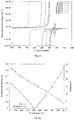
- the properties of the transducer may change as a function of the parametric conditions to which the resonator is subjected. More particularly, transducers with two fingers per wavelength, operating at said Bragg conditions, can see their directivity properties modified during a change in parameters such as a variation in temperature or in mechanical stresses. This then leads to a distortion of the electrical response and can give rise to difficulties in interpreting the measurements or even errors due to frequency jumps during the detection phase. Such a phenomenon is highlighted on the figure 1 where we see the evolution of the response of a single-port synchronous Rayleigh wave resonator as a function of the temperature on a cut langasite substrate (YX lt ) / 48.5 ° / 26.7 ° measured experimentally .
- the curve of the response of the resonator at room temperature exhibits a single peak, hence an unequivocal response.
- the curve measured at the temperature of 150 ° has a major peak and a minor peak.
- the curves corresponding to temperatures 160, 178, 180 and 190 and 200 ° C show almost equal peaks making the interpretation of the response extremely difficult.
- to a conductance of 0.4 S at 200 ° correspond several frequencies.
- the Applicant has sought and developed a solution for which the electrical response of the resonator undergoes less distortion, in particular by exhibiting a resonant frequency which changes continuously as a function of environmental parameters such as temperature, stress, acceleration, pressure. and, more generally, any physical quantity capable of affecting the resonator and of being measured by monitoring the resonant frequency of the resonator.
- continuous evolution is meant here the fact that the conductance / frequency curve exhibits a single maximum in the useful frequency band.
- the invention takes into account the fact that only the Rayleigh waves propagating on single-rotating sections of monocrystalline materials along the X axis are not subject to this directivity phenomenon, more particularly for synchronous structures without space shifting the resonance at within the stop tape of the mirror.
- the invention in fact makes it possible to use any section of piezoelectric material to obtain resonators of controlled spectral purity, in particular sections whose propagation is not collinear with the crystalline axis of the material, in particular sections exhibiting an energy flow angle of less than 2 ° in absolute value.
- the figures 2a and 2b show an estimate of the evolution of the directivity and reflectivity properties of Rayleigh waves under a platinum electrode array on a 48.5 ° / 26.7 ° slice (YX lt) of langasite.
- the figure 2a shows the harmonic admittance for several temperatures and the figure 2b shows the modulus of the reflection coefficient
- the figure 2b highlights the fact that directivity - an angle that can be expressed in degrees - can be canceled out at certain temperatures but also go very far above its value at room temperature.
- the applicant also observes there that the reflection coefficient of the waves on platinum electrodes collapses at temperatures above 300 °. This explains the difficulty in maintaining a constant electrical response over the temperature range, apart from the intrinsic losses of materials which generally increase with temperature.
- the Applicant has developed a structure of transducer electrodes operating outside the forbidden frequency band of Bragg mirrors. Maintenance is obtained over the parametric range to which the resonator is subjected, of a controlled electrical response, reproducible and exhibiting a monotony of the frequency variation as a function of the parameter of interest. Unwanted frequency jumps due to changes in the electrical response are avoided.
- a transducer structure without Bragg condition is not subject to the problem of directivity, a phenomenon linked to the fact that for any section of piezoelectric material, the synchronism of the elastic waves can generate a contribution at the input and at the output of the band. stop, resulting in a multimode spectral response.
- figure 3 shows the evolution of the admittance of a Rayleigh wave on section (YX lt ) / 48.5 ° / 26.7 ° of langasite under infinite periodic lattice of platinum (harmonic analysis) for 3 fingers per wavelength (excitation parameter equal to 1/3) with in (a) the main "low” frequency contribution and in (b) the marginal high frequency contribution.
- the figure 3 illustrates this phenomenon for the section of langasite taken as a basis for comparison but with a resonator with three fingers per wavelength.
- the high frequency contribution is clearly far from the low frequency contribution here sought.
- the high frequency contribution presents almost zero electromechanical coupling for all the temperatures considered here, from 25 to 500 ° C.
- the complex shape of the admittance at this operating point and its change in temperature show that any contribution from the transducer linked to this operating point must be ruled out.
- the 3-finger structure per wavelength eliminates the directivity effect, thanks to operation outside Bragg conditions.
- this type of transducer is used for excitation and detection of waves.
- a wave trap is formed by a Bragg mirror; in other words, an array of electrodes such that its mechanical period is two times smaller than the wavelength of the Rayleigh wave excited by the transducer.
- the design of a resonator combining a transducer without Bragg condition and Bragg mirrors presents differences compared to that of a resonator for which the Bragg condition is respected everywhere.
- Robust design criteria can be established by comparing the extent of the electrical response of the transducer and the spectral coverage of the mirror.
- the goal is then to position the lateral excitation zeros (the transfer function of the transducer follows a law in sin x / x , the zeros in question being the points of cancellation of the function around the central frequency.
- X here takes a value equal to ( ⁇ - ⁇ 0 ) t with ⁇ 0 the synchronism pulsation, for which the excitation of the Rayleigh waves is maximum) of the transducer on the lateral reflection maxima of the Bragg mirrors.
- the invention takes advantage of the operational stability of the transducer operating outside the Bragg condition.
- Structures corresponding to this definition are the transducers with 3 and 4 fingers per wavelength, among others.
- Such electrodes can be used at frequencies compatible with current technological constraints.
- the working frequency limit with a Rayleigh wave propagating at 2600 ms -1 is 928 MHz, or 915 MHz considering a technological guard and a frequency corresponding to a real application (North American ISM band). It is therefore desirable to have structures which make it possible to work at higher frequencies or at least to facilitate technological operations with a larger electrode surface.
- a resonator used as a remotely searchable physical magnitude sensor element may consist of said transducer operating outside the Bragg band and two Bragg condition mirrors, illustrated in figure 4 .
- the transducer stop band is adjusted relative to the mirror stop band to provide the best electrical response in the sense of spectral purity.
- Several operating points are possible as shown in the figures 8 to 10 , going from the positioning of the synchronous frequency to the center of the stop band (Hiccup type structure, see PV Wright, A review of SAW resonator filter technology, Proc. of the IEEE Ultrasonics Symposium, vol.1, pp. 29-38, 1992 ) or at the stop band input (as in the case of a purely synchronous resonator).
- Bragg mirrors can be produced by metallic deposition such as the transducer or by etching of a substrate or any other approach making it possible to produce gratings etched under Bragg conditions.
- the Bragg mirrors can be arranged at distances d 1 and d 2 from the transducer of between 0 and 10 times the wavelength V1 / f1, with f1 the frequency of synchronism of the transducer, so that the propagation of the wave elastic or single mode between each Bragg mirror and the transducer.
- the figure 7 shows the different coincidences between the harmonic electrical response of the grating of the 3-finger transducer per wavelength ⁇ and of the stopband of the grating of the 2-finger Bragg mirrors per wavelength ⁇ as a function of the period of repetition of electrodes.
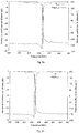
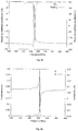
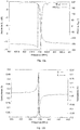
- FIGS 8 , 9 and 10 Three typical cases are considered for which the synchronism of the transducer is located respectively at the lower limit of the stop band of the Bragg mirrors, in the middle of the stop band and in an intermediate situation between the entry and the middle of the stop band.
- the figures 8a , 9a and 10a show the evolution of the reflection coefficient S 11 of the resonator represented in modulus
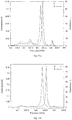
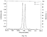
- the figure 11 shows the resonance / anti-resonance ratio for each configuration (a) at the edge of the stop band, (b) between the edge and the center of the stop band, and (c) at the center of the stop band stop.
- the quality coefficient obtained, in figure 11 is of the order of 2500 calculated on the conductance G as the central frequency of the peak divided by its width at mid-height.
- the quality coefficient is linked to the length of the resonator and more particularly to the length of the mirrors and to the low reflectance of the platinum on the Rayleigh waves for this material and this section of langasite in particular. Platinum was considered as an example. It has the drawback of the drop in the modulus of reflection coefficient with temperature. This also means that the configurations described here may not give the highest results in terms of change in resonance with temperature. However, said configurations will retain a main resonance, the behavior of the resonant frequency of which in temperature will remain continuous (no mode jump).
- the figure 11 compares the resonance / antiresonance ratios for each configuration at room temperature.
- Table 1 summarizes the electrode and gap configurations adopted for each resonator simulated previously.
- the frequency f2 can be equal to 657 MHz.
- the frequency f2 can be equal to 660.5 MHz.
- the frequency f4 can be equal to 438 MHz.
- the frequency f5 can be equal to 440 MHz.
- the frequency f6 can be equal to 439 MHz.
- the frequency f7 can be equal to 439 MHz.
- a structure consists of 8 electrodes for 3 wavelengths, which places at 3 ⁇ / 4 ⁇ wavenumber working conditions.
- a structure consists of 7 electrodes for 3 wavelengths, which places at working conditions in wavenumber of 6 ⁇ / 7 ⁇ (the Bragg condition corresponds to a wavenumber of ⁇ / ⁇ ).
- a structure with 5 electrodes for two wavelengths has also been developed corresponding to a number of waves of 4 ⁇ / 5 ⁇ .
- the principle can be formally extended to any combination of electrodes resulting in a deviation from the Bragg frequency but it nevertheless appeared during the simulations that the more the number of consecutive electrodes approached a strict periodic pattern of excitation (alternation + V / -V), the more the contribution at high frequency appears and the losses at the synchronism frequency increase.
- the structures proposed below can therefore be considered to be particularly efficient in operation.
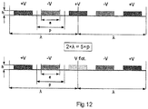
- the 5-finger transducer structure for two wavelengths ( figure 12 ) has an excitation configuration: + V / -V / -V / + V / -V
- the excitation configuration + V / -V / floating / + V / -V is a variant.
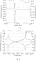
- FIG. 14 shows for a cut (YX lt ) / 48.5 ° / 26.7 ° of langasite, a quality coefficient of more than 100,000 (minimal losses), an electromechanical coupling coefficient is 0.14%. The high frequency contribution between resonance and anti-resonance of the Rayleigh mode is not coupled.
- the calculation for the 5-finger configuration for two wavelengths on section (YX lt ) / 48.5 ° / 26.7 ° of langasite shows in any case the operability of the structure and in particular the spectral purity peak synchronism as a function of temperature.
- the transducer can therefore be advantageously used instead of the transducer with 3 fingers per wavelength, offering greater ease of production in technological terms.
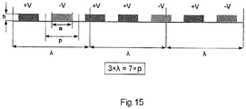
- the periodic network configuration with 7 fingers for 3 lengths is reported in figure 15 for quartz cutting (YXwlt) / - 20 ° / -36.5 ° / + 20 °, illustrating one of the possible excitation modes.
- the 7-finger transducer structure for three wavelengths has an excitation configuration: + V / -V / + V / + V / -V / + V / -V.
- the excitation configuration + V / -V / + V / floating / -V / + V / -V is a variant.
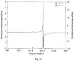
- the synchronism shows an exploitable main contribution and a very weakly coupled secondary contribution.
- the periodic network configuration with 8 fingers for 3 lengths is reported in figure 17 for quartz cutting (YX wlt ) / - 20 ° / -36.5 ° / + 20 °, illustrating one of the possible excitation modes.
- the 8-finger transducer structure for three wavelengths has an excitation configuration: Floating / -V / + V / -V / floating / + V / -V / + V.
- the excitation configuration + V / -V / + V / -V / + V / + V / + V / -V / + V is a variant.
- the synchronism shows an exploitable main contribution and a very weakly coupled secondary contribution.
- the best coupled contribution may be in a high or low position in the frequency plane as shown in the figures 16 and 18 .
- the combination of a transducer operating out of the Bragg condition and Bragg mirrors constitutes a robust approach for sensors liable to see their response significantly altered by the changes in the environment to which they are subjected.
- the invention makes it possible to avoid the jump from one mode to another linked, in particular, to the modification of the directivity properties of the transducer during operation under the Bragg condition.
- the use of this type of transducer on quartz or other piezoelectric material makes it possible to generalize the use of transducers operating outside the Bragg condition and a surface electrode significantly greater than those of conventional structures with 4 and even 3 fingers per wavelength.
- increasing the surface area of the electrodes is advantageous to reach frequencies potentially greater than 1 GHz on quartz and on quartz. langasite.
- a single space g 1 was considered to optimize the electrical response, this space being generally less than or close to the wavelength and optimized to improve the spectral purity of the electrical response of the resonator in a mode configuration. unique. It is however relevant to consider a resonator for which the spaces g 1 and g 2 (cf. figure 6 ) are a multiple (not necessarily an integer multiple) of the wavelength so that several resonances can be established in the intended operating band.
- a cavity is formed between the two Bragg mirrors within which the transducer according to the invention is located. The transducer emits and detects surface waves in the f4-f5 forbidden band of the mirrors but not in its own f2-f3 forbidden band.
- the transducer serves on the one hand to pump the cavity and on the other hand to interrogate it thanks to the reverse and direct piezoelectric effects.
- the Figure 6 is still relevant.
- the space is optimized to allow at least two modes of the cavity to be clearly detected.
- Such a sensor configuration makes it possible to place several resonances in the ISM band as shown in the figure 19 which corresponds to a resonator with at least 3 resonances in said band (centered at 433.9 MHz with a width of 1.7 MHz) and in fact generates interesting functionalities.
- V ⁇ f r ⁇ ⁇ ac .
- This thickness of the metal deposit plays a major role in defining the phase speed of the mode under the array of electrodes.
- the acoustic opening is fixed at 300 ⁇ m.
- the mechanical period within the transducer is 1.987 ⁇ m and in the mirror is 2.957 ⁇ m.
- the first space g 1 therefore represents a length d 1 of 333.333 acoustic wavelengths and the second space g 2 a length d 2 of 333.53 ⁇ ac .
- the frequency f2 can be equal to 657 MHz.
- the frequency f2 can be equal to 660.5 MHz.
- the frequency f4 can be equal to 438 MHz.
- the frequency f5 can be equal to 440 MHz.
- the frequency f6 can be equal to 439 MHz.
- the frequency f7 can be equal to 439 MHz.
- the inter-mirror cavity has a length of 766.86 ⁇ ac , which makes it possible to calculate the difference between modes by considering a phase speed of the Rayleigh wave of approximately 2585 ms -1 for the crystalline orientation chosen and the nature of the electrodes considered here (data calculated by harmonic analysis for an infinite periodic network, assuming this constant value in the resonator which is correct as a first approximation) and a mirror whose total reflection effect would be located unambiguously at its entry point (view of the transducer).
- the Applicant has noticed that the length of the mirror must also be taken into account.
- the parameters ⁇ 1 (i) represent the expansion coefficients of the substrate (generally positive) and the CTV i the temperature coefficients of the speed for a description in development according to the different powers of T.
- V 0 represents the speed phase of elastic surface waves at the reference temperature T 0 .
- V ⁇ (T) represents the phase speed of elastic surface waves at temperature T. Therefore, considering a cut for which the thermal drift of the phase speed is negative, the difference between the peaks decreases with temperature identically to the frequency-temperature law characterizing the surface mode.
- the variation in the frequency difference for example between 100 and 200 ° C of operating temperature, turns out to be around 2 kHz, in line with the results of a calculation based on equation (1), considering the values of the sensitivity coefficients mentioned above announcing a frequency variation of 2.175 kHz on the assumption of a frequency f 0 equal to 680 kHz (the difference between the two modes at 25 ° C.).
- the figure 20 shows the simulation result of the resonator response at 100 and 200 ° C.
- the figure 20 shows the evolution of the response of an asymmetric resonator according to Table 2 with Pt electrodes on langasite (YX lt ) /46.5°/26.7° at two different temperatures, and characterizes the variation of the difference between the two main modes by highlighting the insertion losses induced by the drop in the transduction and reflection coefficients.
- Said resonator configuration is sufficient to illustrate the advantage of the invention insofar as the insertion losses increase quite quickly for this cut, the reflection coefficients (characterizing the mirrors) and conduction (representative of the properties of the transducer) dropping rapidly with temperature.
- Other configurations can be even more spectacular.
- a configuration for which the reflection and transduction coefficients of the resonator exhibit optimum temperature resistance, for example a variation of less than 10% of their nominal value (at 25 ° C) per 100 ° C excursion.
- crystalline orientations will be sought allowing reflection coefficients of the waves which are sufficiently high for a spectral spread of the reflection function as wide as possible.
- Table 2 Geometric characteristics of the structure considered to illustrate the operating mode of the multimode resonator for a differential temperature measurement Material and crystal orientation (IEEE Std-176) Langasite cut (YXlt) /48.5°/26.7° Acoustic opening 300 ⁇ m Nature and thickness of the electrodes Platinum (Pt), 118 nm Structure and length of the transducer 3 fingers / ⁇ ac - 100 ⁇ ac (300 electrodes) Transducer period and metallization ratio 1.989 ⁇ m - 0.5 Structure and length of mirrors 2 fingers / ⁇ ac - 100 ⁇ ac (200 electrodes) Transducer period and metallization ratio 2,973 ⁇ m - 0.5 Length di and d 2 of the cavities gi and g 2 994.5 ⁇ m - 1990 ⁇ m
- figure 22 is plotted the response in admittance of the transducer alone with comparison between the calculation of mixed matrix and the literal expression of the conductance of radiation.
- the answer presents a function aspect of the sinX / X family, representative of the properties of the cut itself.
- the bandwidth of the response is given by the number of wavelengths of the transducer (ie its physical length) and the phase velocity V R of the Rayleigh mode excited by the transducer.
- the phase velocity of the Rayleigh mode excited by the transducer divided by the mode wavelength defines the center frequency of the sinX / X function.
- the duration of a wave packet excited by a Dirac stress is therefore 0.23 ⁇ s corresponding to at a bandwidth of the order of 4.4 MHz (the bandwidth of the spectral response of the -3 dB transducer is approximately 3.8 MHz).
- the acoustic reflection function R ( ⁇ ) of the mirror is reported in figure 23 , virtually covering the main lobe of the transducer response ( figure 22 ).
- the main resonances fall within the 437-440 MHz band corresponding as a first approximation to the overlap of the spectral responses of the transducer and of the mirror taken at mid-height (real part of the admittance figure 22 and modulus of the reflection coefficient figure 23 ).
- the dimensions of the mirror and the transducer depend mainly on the physical characteristics of the mode on the selected material.
- the reflection function fulfilled by the mirror for this configuration is sufficient to create the resonance conditions necessary to generate the multiple modes sought.
- Such a configuration can be improved by adjusting the technological parameters for manufacturing the device, in particular to increase the reflection coefficient here notably less than 1 and the spectral width not completely covering, here, the main lobe of the admittance modulus of the transducer. .
- the reflection coefficient of a multiple electrode Bragg mirror can be calculated relatively simply by considering scalar fields incident and reflected on a single obstacle.
- the so-called mixed matrix formalism aims to connect the acoustic outputs S of each elementary cell (which can be reduced to a single period of the network) to its acoustic inputs E and above all describes the electroacoustic couplings for a given mode of the structure.
- Equation (9) shows the coefficients r and t describing the acoustic diffraction phenomena observed at the edges of the cell (r and t respectively denote the reflection and the transmission).
- r and t respectively denote the reflection and the transmission.
- E 1 S 1 j tan ⁇ e + j cos cos 2 ⁇ cos ⁇ e - j - j tan ⁇
- E 2 S 2 can be cascaded to simulate mirror reflection [ DP Morgan, Surface wave devices for signal processing, Studies in Electrical Eng. 19, Elsevier Ed., 2nd Ed 2007 ].
- the correspondence between the entry and exit terms from one cell (period) to another is desirable during this cascade operation.
- E 'and S' be the input and output of the next cell, connected side 2; these will correspond respectively to the output and input S 2 and E 2 of the first cell (the opposite input and output are denoted respectively E 3 and S 3 ).
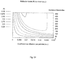
- the figure 24 is a mapping of the reflection function of a mirror with electrodes distributed periodically according to the number of electrodes and the intensity of the unit reflection coefficient. The existence of an optimum for
- unit 1% above 400 electrodes is highlighted.
- the route of the figure 24 is universal and can therefore be applied to any linear physical phenomenon that can be described by equations (9) to (14).
- the reflection coefficient conditions on the one hand the bandwidth of the reflection function and on the other hand the modulus of the reflection function fulfilled by the mirror as a whole. From a unit reflection value greater than 1.5%, 150 electrodes are sufficient to exceed a reflectance of 0.975.
- the calculation shows that it is advantageous to use a reflection coefficient of 0.5 to 1% as soon as it is possible to combine more than 300 electrodes. It is then possible to achieve a reflection coefficient of 0.99. Despite the apparent simplicity of the calculation and its linear nature, the Applicant has demonstrated this optimum, a priori not explained.
- the invention is not limited to the examples of a remote-interrogable elastic surface wave sensor device described above, only by way of example, but it encompasses all the variants that a person skilled in the art may envisage in the field. scope of the following claims.
Landscapes
- Physics & Mathematics (AREA)
- Acoustics & Sound (AREA)
- Surface Acoustic Wave Elements And Circuit Networks Thereof (AREA)
- Measurement Of Mechanical Vibrations Or Ultrasonic Waves (AREA)
- Investigating Or Analyzing Materials By The Use Of Ultrasonic Waves (AREA)
Priority Applications (1)
| Application Number | Priority Date | Filing Date | Title |
|---|---|---|---|
| EP21199059.3A EP3965293A3 (de) | 2014-12-10 | 2015-12-08 | Elastische oberflächenwellen verwendende sensorvorrichtung geeignet zur fernabfrage |
Applications Claiming Priority (2)
| Application Number | Priority Date | Filing Date | Title |
|---|---|---|---|
| FR1462182A FR3030154B1 (fr) | 2014-12-10 | 2014-12-10 | Dispositif de capteur a ondes elastiques de surface a reponse electrique stable |
| EP15198414.3A EP3032742B1 (de) | 2014-12-10 | 2015-12-08 | Elastische oberflächenwellen verwendende sensorvorrichtung geeignet zur fernabfrage |
Related Parent Applications (2)
| Application Number | Title | Priority Date | Filing Date |
|---|---|---|---|
| EP15198414.3A Division EP3032742B1 (de) | 2014-12-10 | 2015-12-08 | Elastische oberflächenwellen verwendende sensorvorrichtung geeignet zur fernabfrage |
| EP15198414.3A Division-Into EP3032742B1 (de) | 2014-12-10 | 2015-12-08 | Elastische oberflächenwellen verwendende sensorvorrichtung geeignet zur fernabfrage |
Related Child Applications (1)
| Application Number | Title | Priority Date | Filing Date |
|---|---|---|---|
| EP21199059.3A Division EP3965293A3 (de) | 2014-12-10 | 2015-12-08 | Elastische oberflächenwellen verwendende sensorvorrichtung geeignet zur fernabfrage |
Publications (2)
| Publication Number | Publication Date |
|---|---|
| EP3793088A2 true EP3793088A2 (de) | 2021-03-17 |
| EP3793088A3 EP3793088A3 (de) | 2021-05-19 |
Family
ID=53059188
Family Applications (3)
| Application Number | Title | Priority Date | Filing Date |
|---|---|---|---|
| EP21199059.3A Pending EP3965293A3 (de) | 2014-12-10 | 2015-12-08 | Elastische oberflächenwellen verwendende sensorvorrichtung geeignet zur fernabfrage |
| EP15198414.3A Active EP3032742B1 (de) | 2014-12-10 | 2015-12-08 | Elastische oberflächenwellen verwendende sensorvorrichtung geeignet zur fernabfrage |
| EP20196942.5A Withdrawn EP3793088A3 (de) | 2014-12-10 | 2015-12-08 | Elastische oberflächenwellen verwendende sensorvorrichtung geeignet zur fernabfrage |
Family Applications Before (2)
| Application Number | Title | Priority Date | Filing Date |
|---|---|---|---|
| EP21199059.3A Pending EP3965293A3 (de) | 2014-12-10 | 2015-12-08 | Elastische oberflächenwellen verwendende sensorvorrichtung geeignet zur fernabfrage |
| EP15198414.3A Active EP3032742B1 (de) | 2014-12-10 | 2015-12-08 | Elastische oberflächenwellen verwendende sensorvorrichtung geeignet zur fernabfrage |
Country Status (2)
| Country | Link |
|---|---|
| EP (3) | EP3965293A3 (de) |
| FR (1) | FR3030154B1 (de) |
Families Citing this family (3)
| Publication number | Priority date | Publication date | Assignee | Title |
|---|---|---|---|---|
| CN114552349A (zh) * | 2020-11-24 | 2022-05-27 | 中国科学技术大学 | 椭圆柱形光学微谐振腔及椭圆柱形光学微谐振腔制备方法 |
| WO2023011716A1 (en) * | 2021-08-05 | 2023-02-09 | Huawei Technologies Co., Ltd. | Surface acoustic wave device with reduced spurious modes |
| EP4526999A1 (de) * | 2022-08-05 | 2025-03-26 | Huawei Technologies Co., Ltd. | Verfahren zur herstellung eines oberflächenwellenresonators |
Citations (1)
| Publication number | Priority date | Publication date | Assignee | Title |
|---|---|---|---|---|
| FR2906630A1 (fr) | 2006-09-29 | 2008-04-04 | Senseor Soc Par Actions Simpli | Dispositif d'interrogation d'un capteur passif de type a ondes acoustiques de surface. |
Family Cites Families (11)
| Publication number | Priority date | Publication date | Assignee | Title |
|---|---|---|---|---|
| US4364016A (en) * | 1980-11-03 | 1982-12-14 | Sperry Corporation | Method for post fabrication frequency trimming of surface acoustic wave devices |
| JPS61205014A (ja) * | 1985-03-08 | 1986-09-11 | Nec Corp | 弾性表面波共振子 |
| WO1990005409A1 (en) * | 1988-11-04 | 1990-05-17 | Cosmo Holdings Pty. Limited | Surface acoustic wave devices |
| JP3266846B2 (ja) * | 1998-01-20 | 2002-03-18 | 東洋通信機株式会社 | 反射反転型弾性表面波変換器及びフィルタ |
| JP3840852B2 (ja) * | 1998-10-15 | 2006-11-01 | セイコーエプソン株式会社 | 弾性表面波装置及び2ポート弾性表面波共振子 |
| US6825794B2 (en) * | 2000-06-02 | 2004-11-30 | Research In Motion Limited | Wireless communication system using surface acoustic wave (SAW) second harmonic techniques |
| FR2864618B1 (fr) * | 2003-12-24 | 2006-03-03 | Temex Sa | Capteur de temperature ou de temperature et de pression interrogeable a distance |
| US7205701B2 (en) * | 2004-09-03 | 2007-04-17 | Honeywell International Inc. | Passive wireless acoustic wave chemical sensor |
| JP4591800B2 (ja) * | 2008-02-20 | 2010-12-01 | エプソントヨコム株式会社 | 弾性表面波デバイスおよび弾性表面波発振器 |
| JP5678486B2 (ja) * | 2010-06-17 | 2015-03-04 | セイコーエプソン株式会社 | 弾性表面波共振子、弾性表面波発振器および電子機器 |
| JP5934464B2 (ja) * | 2010-08-26 | 2016-06-15 | セイコーエプソン株式会社 | 弾性表面波共振子、および弾性表面波発振器、ならびに電子機器 |
-
2014
- 2014-12-10 FR FR1462182A patent/FR3030154B1/fr active Active
-
2015
- 2015-12-08 EP EP21199059.3A patent/EP3965293A3/de active Pending
- 2015-12-08 EP EP15198414.3A patent/EP3032742B1/de active Active
- 2015-12-08 EP EP20196942.5A patent/EP3793088A3/de not_active Withdrawn
Patent Citations (1)
| Publication number | Priority date | Publication date | Assignee | Title |
|---|---|---|---|---|
| FR2906630A1 (fr) | 2006-09-29 | 2008-04-04 | Senseor Soc Par Actions Simpli | Dispositif d'interrogation d'un capteur passif de type a ondes acoustiques de surface. |
Non-Patent Citations (6)
| Title |
|---|
| "Studies in Electrical Eng.", vol. 19, 2007 |
| A. BUNGO: "Analysis of Surface Acoustic Wave Properties of the Rotated Y-cut Langasite Substrate", JAPANESE JOURNAL OF APPLIED PHYSICS, vol. 38, no. 5B |
| E. DIEULESAINTD. ROYER: "Propagation et génération des ondes élastiques", TECHNIQUES DE L'INGÉNIEUR, 10 February 2001 (2001-02-10), pages e3210 |
| J.M. HODÉJ. DESBOIS: "Original basic properties of the Green's functions of a semi-infinite piezoelectric substrate", IEEE ULTRASONICS SYMPOSIUM PROCEEDINGS, vol. l, 1999, pages 131,136 |
| P.V. WRIGHT: "A review of SAW resonator filter technology", PROC. OF THE IEEE ULTRASONICS SYMPOSIUM, vol. l, 1992, pages 29 - 38, XP010103608, DOI: 10.1109/ULTSYM.1992.276068 |
| S. BALLANDRASA. REINHARDTV. LAUDEA. SOUFYANES. CAMOUW. DANIAUT. PASTUREAUDW. STEICHENR. LARDATM. SOLAL: "Simulations of surface acoustic wave devices built on stratified media using a mixed finite element/boundary element intégral formulation", JOURNAL OF APPLIED PHYSICS, vol. 96, no. 12, 2004, pages 7731 - 7741 |
Also Published As
| Publication number | Publication date |
|---|---|
| FR3030154A1 (fr) | 2016-06-17 |
| EP3793088A3 (de) | 2021-05-19 |
| FR3030154B1 (fr) | 2018-11-23 |
| EP3032742B1 (de) | 2020-10-28 |
| EP3965293A2 (de) | 2022-03-09 |
| EP3965293A3 (de) | 2022-06-29 |
| EP3032742A3 (de) | 2016-08-31 |
| EP3032742A2 (de) | 2016-06-15 |
Similar Documents
| Publication | Publication Date | Title |
|---|---|---|
| CA2553861C (fr) | Structure resonante hybride | |
| EP2909932B1 (de) | Wandler mit durch synchrone anregungsstrukturen geführten volumenwellen | |
| EP1222735A1 (de) | Akustisches grenzflächenwellenfilter insbesondere für drahtlose übertragungssysteme | |
| FR2974691A1 (fr) | Dispositif electromecanique a ondes acoustiques comprenant une zone de transduction et une cavite etendue | |
| EP4409743B1 (de) | Oberflächenwellenfilter mit abschnitten stehender wellen | |
| EP2665999B1 (de) | Temperatursensor mit einem akustischen volumenwellenresonator mit hohen obertönen | |
| EP1704396B1 (de) | Aus der ferne testbarer temperatursensor | |
| FR3100405A1 (fr) | Capteur à ondes acoustiques différentiel | |
| EP2156554B1 (de) | Oberflächenwellenresonator mit verminderter störresonanz | |
| EP3032742B1 (de) | Elastische oberflächenwellen verwendende sensorvorrichtung geeignet zur fernabfrage | |
| FR2938136A1 (fr) | Elements de filtres par couplage transverse sur structures resonantes a ondes de volume a resonances harmoniques multiples. | |
| FR3114931A1 (fr) | Structure réflectrice pour dispositifs à ondes acoustiques de surface (SAW) | |
| FR3120489A1 (fr) | Dispositif capteur à ondes acoustiques à deux ports | |
| FR3120488A1 (fr) | Dispositif capteur a ondes acoustiques de surface | |
| WO2015158912A1 (en) | A differential temperature measuring device comprising surface transverse wave resonators | |
| FR2971584A1 (fr) | Capteur de temperature ou de temperature et de pression sans fil, comportant des resonateurs a ondes acoustiques a electrodes en alliage | |
| EP3125428B1 (de) | Elastischer oberflächenwellenresonator in single-port-ausführung auf substrat mit hoher permittivität | |
| WO2025141195A1 (fr) | Dispositif à ondes élastiques | |
| WO2025141194A1 (fr) | Dispositif à ondes élastiques | |
| WO2025141196A2 (fr) | Dispositif à ondes élastiques | |
| FR3157993A1 (fr) | Dispositif à ondes élastiques | |
| WO2025237778A1 (fr) | Dispositif à ondes élastiques | |
| FR3157992A1 (fr) | Dispositif à ondes élastiques | |
| FR3158014A1 (fr) | Dispositif à ondes élastiques |
Legal Events
| Date | Code | Title | Description |
|---|---|---|---|
| PUAI | Public reference made under article 153(3) epc to a published international application that has entered the european phase |
Free format text: ORIGINAL CODE: 0009012 |
|
| STAA | Information on the status of an ep patent application or granted ep patent |
Free format text: STATUS: THE APPLICATION HAS BEEN PUBLISHED |
|
| AC | Divisional application: reference to earlier application |
Ref document number: 3032742 Country of ref document: EP Kind code of ref document: P |
|
| AK | Designated contracting states |
Kind code of ref document: A2 Designated state(s): AL AT BE BG CH CY CZ DE DK EE ES FI FR GB GR HR HU IE IS IT LI LT LU LV MC MK MT NL NO PL PT RO RS SE SI SK SM TR |
|
| PUAL | Search report despatched |
Free format text: ORIGINAL CODE: 0009013 |
|
| AK | Designated contracting states |
Kind code of ref document: A3 Designated state(s): AL AT BE BG CH CY CZ DE DK EE ES FI FR GB GR HR HU IE IS IT LI LT LU LV MC MK MT NL NO PL PT RO RS SE SI SK SM TR |
|
| RIC1 | Information provided on ipc code assigned before grant |
Ipc: H03H 9/02 20060101AFI20210414BHEP Ipc: G01S 13/75 20060101ALI20210414BHEP Ipc: H03H 9/145 20060101ALI20210414BHEP Ipc: H03H 9/64 20060101ALI20210414BHEP Ipc: B60W 50/00 20060101ALN20210414BHEP |
|
| STAA | Information on the status of an ep patent application or granted ep patent |
Free format text: STATUS: THE APPLICATION IS DEEMED TO BE WITHDRAWN |
|
| 18D | Application deemed to be withdrawn |
Effective date: 20211120 |