EP3793237A1 - Von benutzergerät ausgeführtes verfahren und benutzergerät - Google Patents
Von benutzergerät ausgeführtes verfahren und benutzergerät Download PDFInfo
- Publication number
- EP3793237A1 EP3793237A1 EP19800437.6A EP19800437A EP3793237A1 EP 3793237 A1 EP3793237 A1 EP 3793237A1 EP 19800437 A EP19800437 A EP 19800437A EP 3793237 A1 EP3793237 A1 EP 3793237A1
- Authority
- EP
- European Patent Office
- Prior art keywords
- pusch
- subframes
- crbs
- riv
- repetitions
- Prior art date
- Legal status (The legal status is an assumption and is not a legal conclusion. Google has not performed a legal analysis and makes no representation as to the accuracy of the status listed.)
- Withdrawn
Links
Images

Classifications
-
- H—ELECTRICITY
- H04—ELECTRIC COMMUNICATION TECHNIQUE
- H04L—TRANSMISSION OF DIGITAL INFORMATION, e.g. TELEGRAPHIC COMMUNICATION
- H04L1/00—Arrangements for detecting or preventing errors in the information received
- H04L1/12—Arrangements for detecting or preventing errors in the information received by using return channel
- H04L1/16—Arrangements for detecting or preventing errors in the information received by using return channel in which the return channel carries supervisory signals, e.g. repetition request signals
- H04L1/18—Automatic repetition systems, e.g. Van Duuren systems
- H04L1/1812—Hybrid protocols; Hybrid automatic repeat request [HARQ]
- H04L1/1819—Hybrid protocols; Hybrid automatic repeat request [HARQ] with retransmission of additional or different redundancy
-
- H—ELECTRICITY
- H04—ELECTRIC COMMUNICATION TECHNIQUE
- H04L—TRANSMISSION OF DIGITAL INFORMATION, e.g. TELEGRAPHIC COMMUNICATION
- H04L5/00—Arrangements affording multiple use of the transmission path
- H04L5/003—Arrangements for allocating sub-channels of the transmission path
- H04L5/0053—Allocation of signalling, i.e. of overhead other than pilot signals
-
- H—ELECTRICITY
- H04—ELECTRIC COMMUNICATION TECHNIQUE
- H04L—TRANSMISSION OF DIGITAL INFORMATION, e.g. TELEGRAPHIC COMMUNICATION
- H04L1/00—Arrangements for detecting or preventing errors in the information received
- H04L1/08—Arrangements for detecting or preventing errors in the information received by repeating transmission, e.g. Verdan system
-
- H—ELECTRICITY
- H04—ELECTRIC COMMUNICATION TECHNIQUE
- H04L—TRANSMISSION OF DIGITAL INFORMATION, e.g. TELEGRAPHIC COMMUNICATION
- H04L1/00—Arrangements for detecting or preventing errors in the information received
- H04L1/12—Arrangements for detecting or preventing errors in the information received by using return channel
- H04L1/16—Arrangements for detecting or preventing errors in the information received by using return channel in which the return channel carries supervisory signals, e.g. repetition request signals
- H04L1/18—Automatic repetition systems, e.g. Van Duuren systems
- H04L1/1867—Arrangements specially adapted for the transmitter end
- H04L1/1893—Physical mapping arrangements
-
- H—ELECTRICITY
- H04—ELECTRIC COMMUNICATION TECHNIQUE
- H04L—TRANSMISSION OF DIGITAL INFORMATION, e.g. TELEGRAPHIC COMMUNICATION
- H04L5/00—Arrangements affording multiple use of the transmission path
- H04L5/003—Arrangements for allocating sub-channels of the transmission path
- H04L5/0044—Allocation of payload; Allocation of data channels, e.g. PDSCH or PUSCH
-
- H—ELECTRICITY
- H04—ELECTRIC COMMUNICATION TECHNIQUE
- H04L—TRANSMISSION OF DIGITAL INFORMATION, e.g. TELEGRAPHIC COMMUNICATION
- H04L5/00—Arrangements affording multiple use of the transmission path
- H04L5/0091—Signalling for the administration of the divided path, e.g. signalling of configuration information
- H04L5/0094—Indication of how sub-channels of the path are allocated
-
- H—ELECTRICITY
- H04—ELECTRIC COMMUNICATION TECHNIQUE
- H04W—WIRELESS COMMUNICATION NETWORKS
- H04W72/00—Local resource management
- H04W72/04—Wireless resource allocation
- H04W72/044—Wireless resource allocation based on the type of the allocated resource
- H04W72/0446—Resources in time domain, e.g. slots or frames
-
- H—ELECTRICITY
- H04—ELECTRIC COMMUNICATION TECHNIQUE
- H04W—WIRELESS COMMUNICATION NETWORKS
- H04W72/00—Local resource management
- H04W72/20—Control channels or signalling for resource management
- H04W72/23—Control channels or signalling for resource management in the downlink direction of a wireless link, i.e. towards a terminal
-
- H—ELECTRICITY
- H04—ELECTRIC COMMUNICATION TECHNIQUE
- H04W—WIRELESS COMMUNICATION NETWORKS
- H04W4/00—Services specially adapted for wireless communication networks; Facilities therefor
- H04W4/70—Services for machine-to-machine communication [M2M] or machine type communication [MTC]
Definitions
- the present invention relates to the field of wireless communications technologies, and specifically, to a method executed by user equipment, a method performed by a base station, and corresponding user equipment.
- MTC machine type communication
- 3GPP 3rd Generation Partnership Project
- RAN#75 plenary meeting held in March 2017 see non-patent literature: RP-170732: New work item description (WID) on even further enhanced MTC for Long-term Evolution (LTE) , efeMTC for short, and RP-172811 updated in December 2017: Revised WID on even further enhanced MTC for LTE ).
- WID New work item description
- LTE Long-term Evolution
- efeMTC Long-term Evolution
- RP-172811 updated in December 2017: Revised WID on even further enhanced MTC for LTE .
- One of the goals of the efeMTC is to support resource allocation based on sub-physical resource blocks (sub-PRBs) (namely, support resource allocation based on less than one PRB) so as to improve the spectral efficiency of an MTC physical uplink shared channel.
- sub-PRBs sub-physical resource blocks
- MTC user equipment (also referred to as BL/CE UE) in an RRC connected state supports two coverage enhancement modes: a coverage enhancement mode A (CE mode A) and a coverage enhancement mode B (CE mode B).
- CE mode A coverage enhancement mode A
- CE mode B coverage enhancement mode B
- the coverage enhancement mode A is applicable to UE having good channel conditions, requiring no or minimal coverage enhancement, and requiring no or very few repeated transmissions.
- the coverage enhancement mode B is applicable to UE having poor channel conditions, requiring large or quite large coverage enhancement, or requiring many or quite many repeated transmissions.
- PUSCH physical uplink shared channel
- Uplink data transmission of the UE is scheduled by downlink control information (DCI) transmitted by the eNB.
- DCI downlink control information
- a "repetition number" field exists in the DCI to indicate a repeated transmission number used in this PUSCH transmission.
- a subframe is a unit of PUSCH repeated transmission
- a transport block (TB, a size of which is referred to as a Transport block size (TBS))
- TBS Transport block size
- a physical layer entity of the UE performs operations such as channel coding, rate matching, scrambling, modulation, discrete Fourier transform (DFT) pre-coding, and antenna mapping on the transport block, and then maps generated output to allocated time-frequency resources.
- the time-frequency resources are allocated with a resource block pair (RB pair) as a unit, where one resource block pair occupies one subframe in time (for example, a total of 14 OFDM symbols in a normal cyclic prefix).
- RB pair resource block pair
- resource block pairs When more than one resource block pair is allocated, these resource block pairs have different frequency resources, but all fall on the same subframe in time.
- the repetition number of a PUSCH is equal to 1, it may be considered that one repetition is transmitted on allocated PUSCH subframes.
- the repetition number of the PUSCH is greater than 1, it may be considered that one repetition is transmitted on each allocated PUSCH subframe.
- BL/CE subframes and non-BL/CE subframes are distinguished in both an uplink and a downlink.
- a PUSCH can be transmitted only on a BL/CE uplink subframe, and in case of a non-BL/CE uplink subframe, the transmission of the PUSCH is delayed until a BL/CE uplink subframe reappears.
- a PUSCH transmission (assume the repetition number is 4) starting from the subframe n occupies the subframes n, n + 1, n + 3, n + 4.
- the PUSCH transmission spans the five subframes n, n + 1, n + 2, n + 3, and n + 4.
- BL/CE uplink subframes and BL/CE downlink subframes may be separately configured through a higher-layer protocol.
- the smallest resource allocation unit for a PUSCH is one physical resource block (PRB), namely, occupying a bandwidth of 12 subcarriers in the frequency domain (the subcarrier spacing is 15 kHz, and the physical bandwidth of one PRB is 180 kHz).
- PRB physical resource block
- available methods include increasing the transmit power of the UE or increasing the repeated transmission number of the PUSCH.
- the UE has a transmit power limit or a maximum transmit power.
- existing LTE systems already use the maximum transmit power.
- RU resource unit
- One RU occupies x subcarriers in the frequency domain and occupies y subframes in the time domain.
- RU formats may be defined: Number of subcarriers (x) Number of subframes (y) Modulation mode 6 2 QPSK 3 4 QPSK 2(*) 8 Pi/2 BPSK * Three subcarriers are allocated, but only two adjacent subcarriers thereof are used.
- one transport block is subjected to a series of operations such as channel coding and then mapped to one or a plurality of allocated RUs, and then is repeatedly transmitted (when the repetition number is equal to 1, it may also be considered that no repetition exists).
- a series of operations such as channel coding and then mapped to one or a plurality of allocated RUs, and then is repeatedly transmitted (when the repetition number is equal to 1, it may also be considered that no repetition exists).
- an RU format allocated to UE for a PUSCH transmission is 6 subcarriers/2 subframes/QPSK modulation, an RU number is 2, and a repetition number is 8. Then, one PUSCH repetition occupies 4 subframes, and the entire PUSCH transmission occupies a total of 32 subframes.
- a first uplink subframe serial number of the PUSCH is denoted as i 0
- a PUSCH transmission spans N abs PUSCH consecutive subframes (including non-BL/CE uplink subframes).
- N abs PUSCH consecutive subframes including non-BL/CE uplink subframes.
- an index of the redundancy version rv ( j + rv DCI ) mod 4
- • j 0, 1, ..., J PUSCH - 1
- J PUSCH ⁇ N abs PUSCH + i o mod N acc N acc ⁇ .
- the redundancy version ( rv idx ) is determined through the relationship between rv and rv idx in the following table: Redundancy version index rv rv idx 0 0 1 2 2 3 3 1
- two consecutive PUSCH subframes may use different redundancy versions. This applies to the situation where one PUSCH repetition occupies one subframe, but does not apply to the situation where one PUSCH repetition occupies more than one subframe. For example, in the case of sub-PRB resource allocation, one PUSCH repetition may occupy 8 subframes, while one PUSCH repetition can only apply one redundancy version. At this time, a new method for determining a redundancy version must be introduced.
- a common resource allocation mode for a physical downlink shared channel is downlink resource allocation type 0 (DL resource allocation type 0). That is, resource block allocation information (generally indicated through a resource block assignment field in downlink control information (DCI)) includes a bitmap, where each bit indicates whether a specific resource block group (RBG) is allocated to scheduled user equipment (UE).
- DCI downlink control information
- RBG resource block group
- One RBG includes a group of consecutive virtual resource blocks (VRBs) of a localized type, and the virtual resource blocks of the localized type are directly mapped to physical resource blocks (PRBs).
- a virtual resource block 0 is directly mapped to a physical resource block 0, and a virtual resource block 1 is directly mapped to a physical resource block 1.
- RBG sizes in different downlink system bandwidths System bandwidth N RB DL RBG size ( P ) ⁇ 10 1 11 - 26 2 27 - 63 3 64 - 110 4
- the RBG size P 2
- the size of each RBG in the first 12 RBGs is 2 RBs
- the size of the last RBG is 1 RB, as shown in FIG. 1 .
- n RBG 0,1 , ... , N RBG DL ⁇ 1 .
- allocated RBGs are RBG0, RBG2, RBG3, RBG4, RBG5, RBG7, RBG11.
- MTC UE (also referred to as BL/CE UE) in an RRC connected state supports two coverage enhancement modes: a coverage enhancement mode A (CE mode A) and a coverage enhancement mode B (CE mode B).
- CE mode A coverage enhancement mode A
- CE mode B coverage enhancement mode B
- the coverage enhancement mode A is applicable to UE having good channel conditions, requiring no or minimal coverage enhancement, and requiring no or very few repeated transmissions.
- the coverage enhancement mode B is applicable to UE having poor channel conditions, requiring large or quite large coverage enhancement, or requiring many or quite many repeated transmissions.
- some UE only supports a PDSCH bandwidth of 1.4 MHz, some UE supports a PDSCH bandwidth of 5 MHz, while some UE supports a PDSCH bandwidth of 20MHz.
- the UE supporting the PDSCH bandwidth of 5 MHz may also be configured with a maximum PDSCH bandwidth of 1.4 MHz, and the UE supporting the PDSCH bandwidth of 20 MHz may also be configured with the maximum PDSCH bandwidth of 5 MHz or 1.4 MHz.
- the scheme of the present invention is illustrated below by using the maximum PDSCH bandwidth being configured as 1.4 MHz as an example, but the scheme of the present invention also partially or fully applies to other maximum PDSCH bandwidth configurations.
- MTC UE generally uses frequency resources in the system with one or a plurality of narrowbands (NBs) as a unit.
- One NB includes 6 consecutive non-overlapping physical resource blocks.
- N RB DL N RB DL
- a correspondence between PRBs, RBGs, and NBs is as shown in FIG. 2 .
- steps of PDSCH resource allocation thereof are as follows:
- each RIV corresponds to a starting resource block ( RB start ) and a length of a group of consecutively allocated virtual resource blocks ( L CRBS ).
- the serial number of the PRB in the NB is generally 0, so the PRB may also be called the 0th PRB in the NB.
- the first PRB in an RBG is also called similarly in the present invention, that is, the PRB is serially numbered as 0 in the RBG, and may also be sometimes called the 0th PRB in the RBG).
- the PDSCH allocated to the MTC UE may also be configured to perform frequency hopping.
- the following parameters related to frequency hopping are configured by a base station through RRC signaling:
- the frequency hopping of the PDSCH is further controlled by a frequency hopping marker included in DCI. That is, the PDSCH performs frequency hopping only when the RRC parameter mpdcch-pdsch-HoppingConfig indicates activating frequency hopping and the frequency hopping marker in the DCI also indicates frequency hopping.
- NB2 covers the entirety of RBG7 and RBG8 and part of RBG6 and RBG9. If a specific piece of MTC UE is allocated with all 6 PRBs of NB2, then none of RBG6, RBG7, RBG8, and RBG9 can be used for non-MTC UE (if a downlink resource allocation type 0 is used), though PRB12 included in RBG6 and PRB19 included in RBG9 are both idle.
- the present invention is capable of providing a method executed by user equipment and user equipment, which can efficiently determine a redundancy version of a PUSCH in sub-PRB resource allocation.
- a method executed by user equipment comprising: receiving downlink control information; determining, according to the downlink control information, the number of subframes occupied by a PUSCH transmission comprising one or a plurality of PUSCH repetitions; dividing the one or plurality of PUSCH repetitions into one or a plurality of blocks of PUSCH repetitions, wherein each of the one or plurality of blocks of PUSCH repetitions comprises at least one PUSCH repetition; and determining a redundancy version index for each block of PUSCH repetitions.
- each PUSCH repetition is allocated with one or a plurality of resource units, and each resource unit occupies one or a plurality of subframes.
- the number of subframes occupied by the PUSCH transmission comprising one or a plurality of PUSCH repetitions is determined according to the number of PUSCH repetitions, the number of resource units allocated to each PUSCH repetition, and the number of subframes occupied by each resource unit.
- the redundancy version index of each of the blocks of PUSCH repetitions is determined according to a serial number of the block of PUSCH repetitions.
- a method executed by user equipment comprising: receiving downlink control information; determining, according to the downlink control information, the number of subframes occupied by a PUSCH transmission comprising one or a plurality of PUSCH repetitions; dividing the one or plurality of PUSCH repetitions into one or a plurality of blocks of PUSCH repetitions, wherein each of the one or plurality of blocks of PUSCH repetitions comprises at least one PUSCH repetition; determining a reference subframe for each block of PUSCH repetitions; and determining a redundancy version index for the reference subframe to serve as a redundancy version index of a block of PUSCH repetitions where the reference subframe is located.
- each PUSCH repetition is allocated with one or a plurality of resource units, and each resource unit occupies one or a plurality of subframes.
- the number of subframes occupied by the PUSCH transmission comprising one or a plurality of PUSCH repetitions is determined according to the number of PUSCH repetitions, the number of resource units allocated to each PUSCH repetition, and the number of subframes occupied by each resource unit.
- the redundancy version index of the reference subframe is determined according to a serial number of a block of subframes where the reference subframe is located.
- user equipment comprising: a processor; and a memory, storing instructions, wherein when run by the processor, the instructions perform the method described above.
- user equipment comprising: a processor; and a memory, storing instructions, wherein when run by the processor, the instructions perform the method described above.
- a redundancy version of a PUSCH can be efficiently determined in sub-PRB resource allocation.
- a method executed by user equipment comprising: receiving downlink control information (DCI) from a base station, wherein the downlink control information (DCI) comprises resource block allocation information; determining a starting resource block RB start and a length L CRBs of a group of consecutively allocated resource blocks starting from the starting resource block through the resource block allocation information; and receiving a physical downlink shared channel (PDSCH) on resource blocks determined by the starting resource block RB start and the length L CRBs of the resource blocks, wherein the resource block allocation information comprises a resource indication value (RIV) corresponding to an intermediate variable RIV', and the intermediate variable RIV' corresponds to the starting resource block RB start and the length L CRBs of the resource blocks.
- DCI downlink control information
- PDSCH physical downlink shared channel
- a correspondence between the intermediate variable RIV' and the starting resource block RB start and the length L CRBs of the resource blocks may be represented in a table.
- different tables for describing a correspondence between the intermediate variable RIV' and the starting resource block RB start and the length L CRBs of the resource blocks may be defined for different downlink system bandwidths N RB DL .
- the efficiency of resource allocation can be greatly improved.
- a plurality of embodiments according to the present invention are specifically described below by using an LTE mobile communication system and its subsequent evolved version as an exemplary application environment.
- the present invention is not limited to the following embodiments, but may be applied to additional wireless communication systems, such as a 5G mobile communication system and a mobile communication system later than 5G.
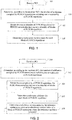
- FIG. 1 is a flowchart of a method executed by user equipment according to Embodiment 1 of the present invention.
- steps executed by the user equipment include:
- Step 105 divide the one or plurality of (for example, R ) PUSCH repetitions included in the PUSCH transmission into one or a plurality of blocks of PUSCH repetitions, where each of the one or plurality of blocks of PUSCH repetitions includes at least one PUSCH repetition.
- every C consecutive PUSCH repetitions are grouped into one block of PUSCH repetitions, and the PUSCH transmission includes a total of ⁇ R/C ⁇ blocks of PUSCH repetitions, where C is a positive integer.
- the blocks of PUSCH repetitions may be serially numbered in time order, where the first block of PUSCH repetitions is serially numbered as 0.
- C may be a predefined value.
- C 1.
- C 1, it may also be considered that the definition of blocks of PUSCH repetitions does not exist; at this time, one block of PUSCH repetitions is equivalent to one PUSCH repetition.
- the value of C may be different for a CE mode A and a CE mode B.
- the value of C may be configured through RRC parameters.
- Step 107 determine a redundancy version index for each block of PUSCH repetitions, then determine a redundancy version according to the redundancy version index, and use the redundancy version as the same redundancy version used by all PUSCH repetitions in the block of PUSCH repetitions.
- redundancy version index rv 0 0 1 2 2 3 3 1
- rv DCI The value of rv DCI may be as follows:
- FIG. 2 is a flowchart of a method executed by user equipment according to Embodiment 2 of the present invention.
- steps executed by the user equipment include:
- Step 205 divide the one or plurality of (for example, R ) PUSCH repetitions included in the PUSCH transmission into one or a plurality of blocks of PUSCH repetitions, where each of the one or plurality of blocks of PUSCH repetitions includes at least one PUSCH repetition.
- every C consecutive PUSCH repetitions are grouped into one block of PUSCH repetitions, and the PUSCH transmission includes a total of ⁇ R/C ⁇ blocks of PUSCH repetitions, where C is a positive integer.
- the blocks of PUSCH repetitions may be serially numbered in time order, where the first block of PUSCH repetitions is serially numbered as 0.
- C may be a predefined value.
- C 1.
- C 1, it may also be considered that the definition of blocks of PUSCH repetitions does not exist; at this time, one block of PUSCH repetitions is equivalent to one PUSCH repetition.
- the value of C may be different for a CE mode A and a CE mode B.
- the value of C may be configured through RRC parameters.
- Step 207 determine a reference subframe for each block of PUSCH repetitions, that is, determine a reference subframe corresponding to each block of PUSCH repetitions.
- the reference subframe may be the first PUSCH subframe in the block of PUSCH repetitions.
- the reference subframe may be the last PUSCH subframe in the block of PUSCH repetitions.
- the reference subframe may be a subframe with a definite serial number in the block of PUSCH repetitions.
- a subframe serially numbered as 4 (assuming that the subframe serial number in the block of PUSCH repetitions starts from 0).
- the subframe with the definite serial number may include only PUSCH subframes, or may include only subframes not transmitting the PUSCH (such as non-BL/CE subframes spanned by the block of PUSCH repetitions), or may include both PUSCH subframes and subframes not transmitting the PUSCH.
- the reference subframe may be a subframe in the block of PUSCH repetitions that is determined according to a preset function.
- Input parameters of the function may include the repetition serial number b of the block of PUSCH repetitions.
- One subframe in the block of PUSCH repetitions may include only PUSCH subframes, or may include only subframes not transmitting the PUSCH (for example, non-BL/CE subframes spanned by the block of PUSCH repetitions), or may include both PUSCH subframes and subframes not transmitting the PUSCH.
- Step 209 for each block of PUSCH repetitions, determine a redundancy version index corresponding to the reference subframe corresponding to the block of PUSCH repetitions, then determine a redundancy version according to the redundancy version index, and use the determined redundancy version as a redundancy version of the block of PUSCH repetitions where the reference subframe is located, namely, the same redundancy version used by all PUSCH repetitions in the block of PUSCH repetitions.
- a first uplink subframe serial number of the PUSCH is denoted as i 0
- rv DCI is determined by a redundancy version field in a DCI format 6-0A.
- rv DCI 0.
- the redundancy version ( rv idx ) is determined through the relationship between rv and rv idx shown in the following table: Redundancy version index rv rv idx 0 0 1 2 2 3 3 1 •
- the value of N acc may be configured through RRC parameters.
- N acc may be a function of C ⁇ N RU ⁇ N t RU , or a function of N RU ⁇ N t RU .
- P may be a predefined value.
- the value of P may be different for the CE mode A and the CE mode B.
- the value of P may be configured through RRC parameters.
- FIG. 3 is a flowchart of a method executed by user equipment according to Embodiment 3 of the present invention.
- steps executed by the user equipment include:
- Step 305 determine one or a plurality of blocks of subframes having a length of N acc to which each PUSCH repetition belongs.
- Step 307 determine a redundancy version of each block of subframes to which the PUSCH repetition belongs using a method similar to the method for determining a redundancy version of a block of PUSCH subframes of MTC UE in the prior art that is described in the Background of the present application, and separately transmit the PUSCH repetition assigned with the determined redundancy version on each of the blocks of subframes.
- one PUSCH repetition occupies a total of 6 subframes ⁇ a, a + 1, a + 2, a + 3, a + 4, a + 5 ⁇ , where subframes ⁇ a, a + 1 ⁇ belong to a block of subframes x, and subframes ⁇ a + 2, a + 3, a + 4, a + 5 ⁇ belong to a block of subframes x + 1, the repetition is punctured and then transmitted on the subframes ⁇ a, a + 1 ⁇ , and a used redundancy version is determined using the prior art based on the block of subframes x; in addition, the repetition is also punctured and then transmitted on the subframes ⁇ a + 2, a + 3, a + 4, a + 5 ⁇ , and a used redundancy version is determined using the prior art based on a block of subframes y.
- steps executed by user equipment are as follows:
- the resource block allocation information includes a resource indication value (RIV), and the value of each RIV corresponds to an RB start and an L CRBs .
- RIV resource indication value
- an integer value indicated by 5 least significant bits (LSBs) of the RIV is greater than 20.
- the PRB indicated by RB start belongs to a set formed by first PRBs of all RBGs in the system.
- the PRB indicated by RB start belongs to a set formed by last PRBs of all RBGs in the system.
- the PRB indicated by RB start belongs to a set formed by first PRBs of all RBGs in the system or a set formed by last PRBs of all RBGs in the system.
- L CRBs belongs to a subset of ⁇ 1, 2, 3, 4, 5, 6 ⁇ or ⁇ 1, 2, 3, 4, 5, 6 ⁇ .
- At least one PRB in the allocated PRBs does not belong to any NB.
- one of the following methods may be used to determine the values of RB start and L CRBs :
- RIV RIV ′
- RB start and L CRBs are determined according to a correspondence between RIV', RB st ⁇ rt , and L CRBs .
- the values of RB start and L CRBs may be mapped to the value of RIV' in a manner listed in a table.
- mapping may be performed in the manner shown in Table 1.
- mapping may be performed in the manner shown in Table 2.
- mapping may be performed in the manner shown in Table 3.
- mapping may be performed in the manner shown in Table 4.
- mapping may be performed in the manner shown in Table 5.
- any of Table 1, Table 2, Table 3, Table 4, and Table 5 is merely a manner for implementing mapping from ( RB start , L CRBs ) to RIV'.
- the mapping relationship from ( RB start , L CRBs ) to RIV' can be arbitrarily changed as long as value sets of both RIV' and ( RB start , L CRBs ) are kept unchanged and the value of each RIV' corresponds to a unique value of ( RB start , L CRBs ).
- any of Table 1, Table 2, Table 3, Table 4, and Table 5 may define only ( RB start , L CRBs ) items where L CRBs and/or RB start satisfies specific value conditions, and not define other ( RB st ⁇ rt , L CRBs ) items.
- RIV' corresponding to each ( RB start , L CRBs ) item can still be allocated from smallest to largest starting from the minimum value of RIV' in the corresponding table.
- the table may define only items with (0, 6), (2, 6), (4, 6), (6, 6), (9, 6) as ( RB start , L CRBs ) values, and values of RIV' corresponding thereto may be 0, 1, 2, 3, and 4.
- the values of RB start and L CRBs may be mapped to the value of RIV in a manner listed in a table.
- mapping may be performed in the manner shown in Table 6.
- mapping may be performed in the manner shown in Table 7.
- mapping may be performed in the manner shown in Table 8.
- mapping may be performed in the manner shown in Table 9.
- mapping may be performed in the manner shown in Table 10.
- any of Table 6, Table 7, Table 8, Table 9, and Table 10 is merely a manner for implementing mapping from ( RB start , L CRBs ) to RIV.
- the mapping relationship from ( RB start , L CRBs ) to RIV can be arbitrarily changed as long as value sets of both RIV and ( RE start , L CRBs ) are kept unchanged and the value of each RIV corresponds to a unique value of ( RE start , L CRBs ) ( L CPBs , RB start ) .
- any of Table 6, Table 7, Table 8, Table 9, and Table 10 may define only ( RE start , L CRBs ) items where L CRBs and/or RB start satisfies specific value conditions, and not define other ( RB start , L CRBs ) items; at this time, RIV corresponding to each ( RE start , L CRBs ) item can still be allocated from smallest to largest starting from the minimum value of RIV in the corresponding table.
- the table may define only items with (0, 6), (2, 6), (4, 6), (6, 6), (9, 6)as ( RB start , L CRBs ) values, and values of RIV corresponding thereto may be 21, 22, 23, 24, and 25.
- FIG. 4 is a block diagram of user equipment (UE) involved in an embodiment of the present invention.
- the user equipment (UE) 40 includes a processor 401 and a memory 402.
- the processor 401 may include, for example, a microprocessor, a microcontroller, an embedded processor, and the like.
- the memory 402 may include, for example, a volatile memory (such as a random access memory (RAM)), a hard disk drive (HDD), a non-volatile memory (such as a flash memory), or another memory.
- the memory 402 stores program instructions. When run by the processor 401, the instructions can perform the aforementioned method executed by user equipment described in detail in the present disclosure.
- the program running in the device according to the present invention may be a program that enables a computer to implement the functions of the embodiments of the present invention by controlling a central processing unit (CPU).
- the program or information processed by the program may be temporarily stored in a volatile memory (such as a random access memory (RAM)), a hard disk drive (HDD), a non-volatile memory (such as a flash memory), or another memory system.
- a volatile memory such as a random access memory (RAM)
- HDD hard disk drive
- non-volatile memory such as a flash memory
- Programs for fulfilling the functions of the various embodiments of the present invention may be recorded in a computer-readable recording medium. Corresponding functions may be fulfilled by causing a computer system to read the programs recorded in the recording medium and execute these programs.
- the so-called “computer system” here may be a computer system embedded in the device, and may include an operating system or hardware (such as peripheral devices).
- the "computer-readable recording medium” may be a semiconductor recording medium, an optical recording medium, a magnetic recording medium, a recording medium storing a program dynamically for a short time, or any other recording medium readable by a computer.
- circuits such as single-chip or multi-chip integrated circuits.
- Circuits designed to execute the functions described in this specification may include a general-purpose processor, a digital signal processor (DSP), an application-specific integrated circuit (ASIC), a field programmable gate array (FPGA), or another programmable logic device, a discrete gate or transistor logic, a discrete hardware component, or any combination of the above devices.
- the general-purpose processor may be a microprocessor, or any existing processor, controller, microcontroller, or state machine.
- the above circuit may be a digital circuit or an analog circuit. In the case of new integrated circuit technologies that replace existing integrated circuits because of advancements in the semiconductor technologies, one or a plurality of embodiments of the present invention may also be implemented using these new integrated circuit technologies.
- the present invention is not limited to the above embodiments. Various examples of the embodiments have been described; however, the present invention is not limited thereto.
- Fixed or non-mobile electronic devices mounted indoors or outdoors may be used as terminal devices or communication devices, such as AV devices, kitchen devices, cleaning devices, air conditioners, office devices, vending machines, and other household appliances.
Landscapes
- Engineering & Computer Science (AREA)
- Signal Processing (AREA)
- Computer Networks & Wireless Communication (AREA)
- Mobile Radio Communication Systems (AREA)
Applications Claiming Priority (2)
| Application Number | Priority Date | Filing Date | Title |
|---|---|---|---|
| CN201810445552.1A CN110474726A (zh) | 2018-05-10 | 2018-05-10 | 由用户设备执行的方法以及用户设备 |
| PCT/CN2019/086183 WO2019214676A1 (zh) | 2018-05-10 | 2019-05-09 | 由用户设备执行的方法以及用户设备 |
Publications (2)
| Publication Number | Publication Date |
|---|---|
| EP3793237A1 true EP3793237A1 (de) | 2021-03-17 |
| EP3793237A4 EP3793237A4 (de) | 2022-03-02 |
Family
ID=68467819
Family Applications (1)
| Application Number | Title | Priority Date | Filing Date |
|---|---|---|---|
| EP19800437.6A Withdrawn EP3793237A4 (de) | 2018-05-10 | 2019-05-09 | Von benutzergerät ausgeführtes verfahren und benutzergerät |
Country Status (4)
| Country | Link |
|---|---|
| US (1) | US11652596B2 (de) |
| EP (1) | EP3793237A4 (de) |
| CN (1) | CN110474726A (de) |
| WO (1) | WO2019214676A1 (de) |
Cited By (1)
| Publication number | Priority date | Publication date | Assignee | Title |
|---|---|---|---|---|
| WO2025171930A1 (en) * | 2024-02-15 | 2025-08-21 | Nokia Technologies Oy | Redundancy determination in pusch repetitions with orthogonal cover code |
Families Citing this family (12)
| Publication number | Priority date | Publication date | Assignee | Title |
|---|---|---|---|---|
| US11831571B2 (en) * | 2018-10-31 | 2023-11-28 | Qualcomm Incorporated | Transport block transmission using different spatial parameters |
| JP7337928B2 (ja) * | 2019-07-10 | 2023-09-04 | 株式会社Nttドコモ | 端末、無線通信方法、基地局及びシステム |
| EP4042803A1 (de) * | 2019-11-07 | 2022-08-17 | Huawei Technologies Co., Ltd. | Verfahren und vorrichtung zur ressourcenreservierung in schmalband-internet-der-dinge-kommunikation |
| US11588523B2 (en) * | 2020-01-17 | 2023-02-21 | Qualcomm Incorporated | TPMI and/or SRI indication for codebook-based PUSCH repetition |
| CN113258969B (zh) | 2020-02-13 | 2022-08-09 | 华为技术有限公司 | 发送物理上行共享信道的方法及装置 |
| EP4104582B1 (de) * | 2020-02-14 | 2026-04-29 | Lenovo (Beijing) Limited | Verfahren und vorrichtung zur planung von pusch oder pdsch |
| EP4140206A4 (de) * | 2020-04-22 | 2024-01-17 | Lenovo (Beijing) Limited | Verfahren und vorrichtung zur leistungssteuerung der pusch-wiederholung |
| JPWO2021229777A1 (de) * | 2020-05-14 | 2021-11-18 | ||
| EP4169322B1 (de) * | 2020-08-05 | 2025-11-12 | Apple Inc. | Mehrfache pdsch/pusch-übertragungsplanung mit wiederholung |
| WO2022027369A1 (en) | 2020-08-05 | 2022-02-10 | Apple Inc. | Unlicensed spectrum frame based equipment channel sensing techniques |
| WO2022067752A1 (en) | 2020-09-30 | 2022-04-07 | Zte Corporation | Systems and methods for enhancing uplink transmission |
| CN122248476A (zh) * | 2026-05-24 | 2026-06-19 | 上海芯源创新中心 | 一种信息传输方法、装置、电子设备及介质 |
Family Cites Families (8)
| Publication number | Priority date | Publication date | Assignee | Title |
|---|---|---|---|---|
| JP6378192B2 (ja) * | 2012-11-13 | 2018-08-22 | エルジー エレクトロニクス インコーポレイティド | データ送信方法及び装置、並びにデータ送信方法及び装置 |
| EP3026829B1 (de) * | 2013-07-26 | 2020-09-02 | LG Electronics Inc. | Verfahren zur übertragung von signalen für mtc und vorrichtung dafür |
| CN104780549A (zh) * | 2014-01-10 | 2015-07-15 | 夏普株式会社 | 物理信道配置方法以及基站和用户设备 |
| KR101865643B1 (ko) * | 2014-03-21 | 2018-06-08 | 후아웨이 테크놀러지 컴퍼니 리미티드 | 제어 정보 강화 전송 방법, 사용자 기기, 기지국, 및 통신 시스템 |
| US9955356B2 (en) * | 2014-09-25 | 2018-04-24 | Intel IP Corporation | System and method of handling uplink transmission collision for enhanced coverage mode UEs |
| US11044709B2 (en) * | 2016-03-11 | 2021-06-22 | Qualcomm Incorporated | Power savings for downlink channel monitoring in narrowband systems |
| WO2018175521A1 (en) * | 2017-03-24 | 2018-09-27 | Intel IP Corporation | Sub-prb resource allocation for pusch in even further enhanced mtc |
| CN113767691A (zh) | 2019-05-02 | 2021-12-07 | 夏普株式会社 | 用于在微时隙pusch上进行冗余版本确定的用户设备、基站和方法 |
-
2018
- 2018-05-10 CN CN201810445552.1A patent/CN110474726A/zh active Pending
-
2019
- 2019-05-09 US US17/054,508 patent/US11652596B2/en active Active
- 2019-05-09 EP EP19800437.6A patent/EP3793237A4/de not_active Withdrawn
- 2019-05-09 WO PCT/CN2019/086183 patent/WO2019214676A1/zh not_active Ceased
Cited By (1)
| Publication number | Priority date | Publication date | Assignee | Title |
|---|---|---|---|---|
| WO2025171930A1 (en) * | 2024-02-15 | 2025-08-21 | Nokia Technologies Oy | Redundancy determination in pusch repetitions with orthogonal cover code |
Also Published As
| Publication number | Publication date |
|---|---|
| US11652596B2 (en) | 2023-05-16 |
| EP3793237A4 (de) | 2022-03-02 |
| CN110474726A (zh) | 2019-11-19 |
| WO2019214676A1 (zh) | 2019-11-14 |
| US20210194656A1 (en) | 2021-06-24 |
Similar Documents
| Publication | Publication Date | Title |
|---|---|---|
| US11652596B2 (en) | Method executed by user equipment, and user equipment | |
| EP3606218B1 (de) | Benutzerausrüstung, basisstation und entsprechendes verfahren | |
| US11102770B2 (en) | Resource allocation method, network device, and terminal device | |
| US11219020B2 (en) | Determination of data transmission resources | |
| US11297615B2 (en) | Wireless communication method and device | |
| US9019982B2 (en) | Wireless communication base station device, wireless communication terminal device and CCE allocation method | |
| CN113615244A (zh) | 用户设备、基站和方法 | |
| US11736262B2 (en) | User equipment, base station, and related method | |
| CN115580938A (zh) | 一种数据的传输方法及装置 | |
| CN114006686B (zh) | 一种传输方法、装置和存储介质 | |
| US20210298011A1 (en) | Apparatus and method for a mobile telecommunications system | |
| JP2019507512A (ja) | Enodeb、ユーザ機器および無線通信方法 | |
| CN110536421B (zh) | 通信方法和装置 | |
| EP2870811B1 (de) | Verfahren und netzwerkknoten zur zuweisung von ressourcen eines uplink-subframes | |
| WO2017101799A1 (zh) | 信息的传输方法、装置及计算机存储介质 | |
| US11171755B2 (en) | Communication method and communications device | |
| EP3713137A1 (de) | Ack-/nack-ressourcenzuteilungsverfahren sowie entsprechendes benutzergerät und basisstation | |
| CN110351853A (zh) | 由用户设备执行的方法以及用户设备 | |
| EP4395438A1 (de) | Kommunikationsverfahren und -vorrichtung, vorrichtung und speichermedium | |
| US20260006596A1 (en) | Resource indication method, terminal device, and network device | |
| EP4668956A1 (de) | Verfahren und vorrichtung zur bestimmung der transportblockgrösse, vorrichtung und speichermedium | |
| EP4387359A1 (de) | Datenübertragungsverfahren und kommunikationsvorrichtung |
Legal Events
| Date | Code | Title | Description |
|---|---|---|---|
| STAA | Information on the status of an ep patent application or granted ep patent |
Free format text: STATUS: THE INTERNATIONAL PUBLICATION HAS BEEN MADE |
|
| PUAI | Public reference made under article 153(3) epc to a published international application that has entered the european phase |
Free format text: ORIGINAL CODE: 0009012 |
|
| STAA | Information on the status of an ep patent application or granted ep patent |
Free format text: STATUS: REQUEST FOR EXAMINATION WAS MADE |
|
| 17P | Request for examination filed |
Effective date: 20201210 |
|
| AK | Designated contracting states |
Kind code of ref document: A1 Designated state(s): AL AT BE BG CH CY CZ DE DK EE ES FI FR GB GR HR HU IE IS IT LI LT LU LV MC MK MT NL NO PL PT RO RS SE SI SK SM TR |
|
| AX | Request for extension of the european patent |
Extension state: BA ME |
|
| DAV | Request for validation of the european patent (deleted) | ||
| DAX | Request for extension of the european patent (deleted) | ||
| A4 | Supplementary search report drawn up and despatched |
Effective date: 20220127 |
|
| RIC1 | Information provided on ipc code assigned before grant |
Ipc: H04L 1/18 20060101ALI20220121BHEP Ipc: H04L 1/08 20060101ALI20220121BHEP Ipc: H04W 72/04 20090101ALI20220121BHEP Ipc: H04W 24/00 20090101AFI20220121BHEP |
|
| STAA | Information on the status of an ep patent application or granted ep patent |
Free format text: STATUS: EXAMINATION IS IN PROGRESS |
|
| 17Q | First examination report despatched |
Effective date: 20221012 |
|
| STAA | Information on the status of an ep patent application or granted ep patent |
Free format text: STATUS: THE APPLICATION IS DEEMED TO BE WITHDRAWN |
|
| 18D | Application deemed to be withdrawn |
Effective date: 20230223 |