EP3793263A1 - Kommunikationsverfahren und -vorrichtung - Google Patents
Kommunikationsverfahren und -vorrichtung Download PDFInfo
- Publication number
- EP3793263A1 EP3793263A1 EP19799203.5A EP19799203A EP3793263A1 EP 3793263 A1 EP3793263 A1 EP 3793263A1 EP 19799203 A EP19799203 A EP 19799203A EP 3793263 A1 EP3793263 A1 EP 3793263A1
- Authority
- EP
- European Patent Office
- Prior art keywords
- cause value
- terminal
- protocol layer
- rrc connection
- radio access
- Prior art date
- Legal status (The legal status is an assumption and is not a legal conclusion. Google has not performed a legal analysis and makes no representation as to the accuracy of the status listed.)
- Granted
Links
Images




Classifications
-
- H—ELECTRICITY
- H04—ELECTRIC COMMUNICATION TECHNIQUE
- H04W—WIRELESS COMMUNICATION NETWORKS
- H04W48/00—Access restriction; Network selection; Access point selection
- H04W48/16—Discovering, processing access restriction or access information
-
- H—ELECTRICITY
- H04—ELECTRIC COMMUNICATION TECHNIQUE
- H04W—WIRELESS COMMUNICATION NETWORKS
- H04W76/00—Connection management
- H04W76/20—Manipulation of established connections
- H04W76/27—Transitions between radio resource control [RRC] states
-
- H—ELECTRICITY
- H04—ELECTRIC COMMUNICATION TECHNIQUE
- H04W—WIRELESS COMMUNICATION NETWORKS
- H04W76/00—Connection management
- H04W76/10—Connection setup
-
- H—ELECTRICITY
- H04—ELECTRIC COMMUNICATION TECHNIQUE
- H04W—WIRELESS COMMUNICATION NETWORKS
- H04W76/00—Connection management
- H04W76/10—Connection setup
- H04W76/15—Setup of multiple wireless link connections
- H04W76/16—Involving different core network technologies, e.g. a packet-switched [PS] bearer in combination with a circuit-switched [CS] bearer
-
- H—ELECTRICITY
- H04—ELECTRIC COMMUNICATION TECHNIQUE
- H04W—WIRELESS COMMUNICATION NETWORKS
- H04W88/00—Devices specially adapted for wireless communication networks, e.g. terminals, base stations or access point devices
- H04W88/02—Terminal devices
- H04W88/06—Terminal devices adapted for operation in multiple networks or having at least two operational modes, e.g. multi-mode terminals
-
- H—ELECTRICITY
- H04—ELECTRIC COMMUNICATION TECHNIQUE
- H04W—WIRELESS COMMUNICATION NETWORKS
- H04W88/00—Devices specially adapted for wireless communication networks, e.g. terminals, base stations or access point devices
- H04W88/08—Access point devices
- H04W88/10—Access point devices adapted for operation in multiple networks, e.g. multi-mode access points
Definitions
- This application relates to communications technologies, and in particular, to a communication method and a communications apparatus.
- a future radio network system may include a plurality of radio access technologies, for example, one or more of a second generation (2nd Generation, 2G) wireless communications technology, a third generation (3rd Generation, 3G) wireless communications technology, a fourth generation (4th Generation, 4G) wireless communications technology, a fifth generation (5th Generation, 5G) wireless communications technology, and a radio access technology that further evolves in the future.
- the future radio network system may further include a radio access technology that is not defined by a 3GPP organization, for example, a wireless local area network (Wireless LAN, WLAN), Bluetooth, or a short-range communications technology.
- a radio access network device that supports one or more radio access technologies may be connected to a plurality of core networks that use different technologies.
- Types of the core networks may be a 2G core network, a 3G core network, an evolved packet core (The Evolved Packet Core, EPC), a 5G core network (5G Core, 5GC), a type of a core network that further evolves in the future, and the like.
- EPC evolved packet core
- 5G Core 5G Core
- 5GC 5G core network that further evolves in the future, and the like.
- service types are increasingly diversified, capabilities of a terminal and the radio access network device are increasingly strong. Therefore, when the terminal establishes a connection to the radio access network device, the terminal is expected to provide more connection establishment cause values for processing and network optimization by a radio access network.
- the radio access device When the radio access device provides, by using one radio access technology for the terminal, services of a plurality of core networks using different technologies, cause values corresponding to wireless communications systems to which the plurality of core networks belong need to be carried in a message format defined by a same radio access technology.
- a method for processing a cause value needs to be provided, so that when the terminal accesses different core networks by using a same radio access technology, the terminal can successfully report the cause value.
- This application provides a communication method and a communications apparatus, so that when a terminal accesses different core networks by using one radio access technology, the terminal can successfully report a cause value.
- a first aspect of this application provides a communication method.
- the method includes: A terminal first determines a first radio access technology for establishing an RRC connection; and then the terminal determines, based on access information, a first cause value for establishing the RRC connection, where the first cause value is a cause value of the first radio access technology, and the access information includes at least one of an access identity AI, an access category AC, or a second cause value of a second radio access technology.
- the terminal sends a first message used to establish the RRC connection, and uses the first message to carry the first cause value.
- the terminal may determine the first cause value based on the access information including at least one of the AI, the AC, or the second cause value, where the first cause value is the cause value of the first radio access technology, and the second cause value is a cause value of the second radio access technology. Therefore, when a radio access device provides, by using one radio access technology for the terminal, services of a plurality of core networks using different technologies, cause values that are sent by the terminal to the radio access device and that are used for communication with different core networks may be carried in a message format defined by a same radio access technology. In this way, when the terminal accesses a plurality of core networks by using one radio access technology, the terminal can successfully report a cause value.
- a first cause value of E-UTRA is used.
- the terminal may determine an E-UTRA cause value based on at least one of the AI, the AC, or an NR cause value.
- the terminal may also use the E-UTRA to report the cause value to the ng-eNB. This ensures that the terminal can successfully report the cause value when the terminal accesses the EPC and the 5GC through the ng-eNB.
- the terminal may determine the first cause value based on a mapping relationship between the second cause value and the first cause value.
- the terminal may determine the first cause value based on a mapping relationship between the AI and the first cause value.
- the terminal may determine the first cause value based on a mapping relationship between the AC and the first cause value.
- a first protocol layer of the terminal may determine the first cause value based on the access information.
- a second protocol layer of the terminal may obtain the first cause value from the first protocol layer of the terminal, and the second protocol layer sends the first message including the first cause value.
- a second protocol layer of the terminal may obtain the access information from a first protocol layer of the terminal, and the second protocol layer of the terminal determines the first cause value based on the access information.
- the first radio access technology includes an evolved universal terrestrial radio access E-UTRA technology
- the second radio access technology includes a new radio NR technology.
- the first protocol layer is a non-access stratum NAS
- the second protocol layer is an RRC layer.
- the establishing an RRC connection includes establishing a new RRC connection, resuming an RRC connection, or reestablishing an RRC connection.
- mapping relationship between the second cause value and the first cause value may be preconfigured in any one of the following manners: NAS signaling message configuration, operation, administration and maintenance OAM configuration, operator preconfiguration, and default configuration.
- mapping relationship between the AI and the first cause value may be preconfigured in any one of the following manners: NAS signaling message configuration, operation, administration and maintenance OAM configuration, operator preconfiguration, and default configuration.
- mapping relationship between the AC and the first cause value may be preconfigured in any one of the following manners: NAS signaling message configuration, operation, administration and maintenance OAM configuration, operator preconfiguration, and default configuration.
- a second aspect of this application provides a communications apparatus.
- the communications apparatus includes a processor, where the processor is configured to be coupled to a memory, and read and execute instructions in the memory, to implement the method in the first aspect.
- the communications apparatus may further include a transceiver, configured to support the communications apparatus in sending and receiving data, signaling, or information in the method in the first aspect, for example, sending the first message.
- the communications apparatus may be a terminal device, or may be some apparatuses in a terminal device, for example, a chip system in a terminal device.
- the chip system is configured to support a terminal device in implementing the functions in the foregoing aspect, for example, generating, receiving, sending, or processing the data and/or the information in the foregoing method.
- the chip system further includes a memory.
- the memory is configured to store a program instruction and data that are necessary for the terminal device.
- the chip system includes a chip, and may further include another discrete device or circuit structure.
- a third aspect of this application provides a communications apparatus.
- the communications apparatus has functions of implementing the first aspect.
- the functions may be implemented by hardware, or may be implemented by hardware executing corresponding software.
- the hardware or the software includes one or more modules corresponding to the foregoing functions.
- the communications apparatus may include a processing module and a sending module.
- the processing module and the sending module may perform corresponding functions in the foregoing method.
- the processing module is configured to determine a first radio access technology for establishing an RRC connection, and determine, based on access information, a first cause value for establishing the RRC connection, where the access information includes at least one of an AI, an AC, or a second cause value of a second radio access technology; and the sending module is configured to send a first message, where the first message is used to request to establish the RRC connection, and the first message includes the first cause value.
- a fourth aspect of this application provides a readable storage medium.
- the storage medium stores a computer program, and the computer program includes instructions used to perform the method according to the first aspect.
- a fifth aspect of this application provides a computer program product.
- the computer program product includes computer program code, and when the computer program code is executed, a computer is enabled to perform the method according to the first aspect.
- the computer program code can be stored in a first storage medium.
- the first storage medium can be encapsulated with a processor, or encapsulated separately from a processor. This is not specifically limited in this embodiment of this application.
- a 4G wireless communications system performs communication based on an evolved universal terrestrial radio access (Evolved-UMTS Terrestrial Radio Access, E-UTRA) technology
- a 5G wireless communications system (5G System, 5GS) performs communication based on a new radio (New Radio, NR) technology
- a terminal may be connected to a radio access network device by using one or more radio access technologies. For example, different terminals may separately access a 5G core network by using the NR technology and the E-UTRA technology. Therefore, NAS layers used by the different terminals are all 5GS NASs, and RRC layers used by the different terminals are corresponding NR RRC layers or E-UTRA RRC layers.
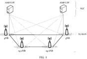
- FIG. 1 is a system architectural diagram of a 5G wireless communications system.
- the 5G wireless communications system mainly includes a 5GC and a 5G RAN (also referred to as an NG-RAN).
- the 5GC is a core network of a 5GS, and may include an access and mobility management function (Access and Mobility Management Function, AMF), a user plane function (User Plane Function, UPF), and another network element.
- the 5G RAN is a radio access network in the 5G wireless communications system.
- a gNB and an ng-eNB.
- the gNB provides termination points of a user plane protocol stack and a control plane protocol stack of NR for a terminal.
- the ng-eNB provides termination points of a user plane protocol stack and a control plane protocol stack of E-UTRA for the terminal.
- the ng-eNB may be connected to the 5GC, so that the terminal accesses the 5GC through the ng-eNB.
- the ng-eNB may be connected to a 4G EPC, so that the terminal accesses the EPC through the ng-eNB.
- an ng-eNB E-UTRA technology provides a radio transmission resource for the terminal, and provides a 5GC service for the terminal.
- the ng-eNB may be connected only to the 5GC or the EPC, or the ng-eNB may be connected to both the 5GC and the EPC.
- FIG. 2 is a schematic connection diagram showing that the ng-eNB is connected to both the 5GC and the EPC. As shown in FIG. 2 , the ng-eNB is connected to both the 5GC and the EPC.
- the terminal can access the EPC through a traditional eNB and access the 5GC through the gNB.
- both the ng-eNB and the gNB are connected to the 5GC, and the terminal may access the 5GC through the ng-eNB or the gNB.
- the ng-eNB and the gNB may be connected to each other, to implement communication between base stations and exchange information related to the terminal.
- the ng-eNB and the eNB are connected to each other, to implement communication between base stations and exchange the information related to the terminal.
- a traditional LTE terminal may access the EPC through the eNB or the ng-eNB. It can be learned from the foregoing that a terminal may access the 5GC through the gNB, or may access the 5GC through the ng-eNB.
- the ng-eNB may be connected to both the 5GC and the EPC.
- FIG. 3 is an architectural diagram of a protocol stack of a terminal that supports two radio access technologies and a connection between the terminal and an ng-eNB.
- the terminal supports both an NR technology and an E-UTRA technology, that is, the terminal can access both a 5GC and an EPC. It is assumed that the terminal supports access to the 5GC through both a gNB and the ng-eNB. In this case, as shown in FIG.
- the terminal supports an NR air interface protocol stack, including, for example, an NR RRC protocol layer, an NR lower protocol layer (for example, an RLC layer, a MAC layer, and a PHY layer), and a non-access stratum (Non-Access Stratum, NAS) defined for the 5GS, which is referred to as a 5GS NAS protocol layer for short.
- the terminal further supports an E-UTRA air interface protocol stack, including, for example, an E-UTRA RRC protocol layer, an E-UTRA lower protocol layer, and the 5GS NAS protocol layer.
- the terminal supports access to the EPC through the ng-eNB or an eNB, so that the terminal further needs to support a NAS protocol layer defined for the EPS, which is referred to as an EPS NAS for short.
- the terminal supports one access manner, the terminal needs to support a corresponding protocol stack inside. That is, if the terminal has a capability of accessing the 5GC through E-UTRA, the terminal needs to have at least the 5GS NAS protocol layer and the E-UTRA RRC protocol layer. If the terminal has a capability of accessing the 5GC through NR, the terminal needs to have at least the 5GS NAS protocol layer and the NR RRC protocol layer.
- the terminal needs to have at least the EPS NAS protocol layer and the E-UTRA RRC protocol layer.
- the terminal needs to have at least the EPS NAS protocol layer and the E-UTRA RRC protocol layer.
- the terminal does not have the NR RRC protocol layer and the NR lower layer shown in FIG. 3 .
- the technical solutions in this embodiment of this application may also be applied.
- the terminal does not have the EPS NAS shown in FIG. 3
- the technical solutions in this embodiment of this application may also be applied.
- an existing terminal Before sending signaling or data to a core network (for example, the 5GC or the EPC), an existing terminal first needs to send an RRC request to a base station (for example, a gNB or an ng-eNB), to establish an RRC connection.
- a base station for example, a gNB or an ng-eNB
- the RRC request may be used to request to establish a new RRC connection or resume an RRC connection.
- the resuming an RRC connection may be: when UE switches from a third state (or referred to as an inactive (inactive) state) to a connected state, resuming a suspended RRC connection to an RRC connection that can be used for normal communication.
- a specific RRC message may be an RRC connection request (that is, RRC Connection Request), an RRC setup request (that is, RRC Setup Request), an RRC resume request (that is, RRC Resume Request), an RRC connection resume request (that is, RRC Connection Resume Request), or the like.
- RRC Connection Request that is, RRC Connection Request
- RRC setup request that is, RRC Setup Request
- RRC resume request that is, RRC Resume Request
- RRC connection resume request that is, RRC Connection Resume Request
- an emergency that is, emergency
- high priority access that is, high Priority Access
- mobile terminating access mobile terminating access, mt-Access
- mobile originating signalling mobile originating signaling, mo-Signalling
- mobile originating data mobile originating data, mo-Data
- delay tolerant access that is, delay Tolerant Access
- a mobile originating voice call mobile originating voice call, mo-Voice Call.
- a quantity of cause values that may be carried by the terminal in the RRC request may be greater than seven specified in an EPS system, for example, may be eight or more than eight. If a relatively large quantity of cause values are specified in the 5GS, more fields need to be occupied in the RRC request to carry the cause values.
- the cause value in the RRC request sent when the terminal accesses the 5GC is generated by the 5GS NAS, and then sent by a lower-layer protocol stack via the RRC message. If the terminal accesses the 5GC through the gNB, the terminal sends an RRC request to the gNB.
- the gNB provides a radio transmission resource for the terminal by using the NR technology, and as new radio, the NR may define a new RRC message format, more fields than those in the EPS may be directly used to carry the cause values.
- the terminal accesses the 5GC through the ng-eNB, the terminal needs to send an RRC request to the ng-eNB.
- the ng-eNB provides a radio transmission resource for the terminal by using the E-UTRA technology. Therefore, a length of fields occupied by the cause value in the RRC request needs to comply with a specification in an E-UTRA protocol, that is, a quantity of cause values is 7 (at most 8). In this case, if the terminal does not perform corresponding processing on the cause value before sending the RRC request to the ng-eNB, an exception occurs when the cause value is sent.
- the terminal described in the following embodiments of this application is any terminal that can access the 5GC through the ng-eNB.
- the terminal may include but is not limited to a terminal device applied to an internet of things, for example, may be a terminal device that accesses an NB-IoT (which may be referred to as an "NB-IoT terminal"): a smart meter reading device, a logistics tracking device, an environment monitoring device, or the like.
- the terminal may further include but is not limited to a mobile station (Mobile Station, MS), a mobile terminal (Mobile Terminal), a mobile telephone (Mobile Telephone), user equipment (User Equipment, UE), a handset (handset), portable equipment (portable equipment), and the like.
- the terminal device may communicate with one or more core networks through a radio access network (Radio Access Network, RAN).
- RAN Radio Access Network
- the terminal device may be a mobile phone (or referred to as a "cellular" phone) or a computer having a wireless communication function.
- the terminal device may be a portable, pocket-sized, handheld, computer built-in, or vehicle-mounted mobile device.
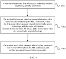
- FIG. 4 is a schematic flowchart of Embodiment 1 of a communication method according to this application. As shown in FIG. 4 , the method includes the following steps.
- a terminal determines a first radio access technology for establishing an RRC connection.
- a first protocol layer of the terminal may obtain, from a second protocol layer, the first radio access technology for establishing the RRC connection.
- the first protocol layer may be a NAS
- the second protocol layer may be an RRC layer.
- the first protocol layer may be specifically the 5GS NAS shown in FIG. 3
- the second protocol layer may be the E-UTRA RRC shown in FIG. 3 .
- the first protocol layer is the 5GS NAS and the second protocol layer is the E-UTRA RRC.
- the first protocol layer and the second protocol layer may alternatively be protocol layers of another wireless communications system or access technology.
- the first radio access technology may be E-UTRA.
- the terminal determines, based on access information, a first cause value for establishing the RRC connection, where the first cause value is a cause value of the first radio access technology, and the access information includes at least one of an access identity (Access Identity, AI), an access category (Access Category, AC), or a second cause value of a second radio access technology.
- That the access information includes at least one of an AI, an AC, or a second cause value of a second radio access technology specifically includes the following several cases:
- a process of obtaining the AI and the AC may be as follows:
- the 5GS NAS detects in real time whether an access attempt (access attempt) triggered by one of the following events occurs:
- the 5GS NAS When detecting that one of the foregoing events occurs, the 5GS NAS obtains at least one AI and one AC based on a preset mapping relationship.
- the preset mapping relationship may be specifically a mapping relationship specified in a protocol.
- AIs may be distinguished by AI identifiers or index values. For example, an AI 0 and an AI 1 separately identify AIs with specific meanings.
- ACs may also be distinguished by AC identifiers or index values. For example, an AC 0 and an AC 1 separately identify ACs with specific meanings.
- the 5GS NAS is mapped to the AI 1.
- a mission critical service MCS
- MCS Mobility Critical Service
- the 5GS NAS is mapped to the AC 0. If the type of the access attempt is an emergency call, the 5GS NAS is mapped to an AC 2.
- a process of obtaining the second cause value is as follows: The 5GS NAS determines the second cause value based on at least one of the AI, the AC, or the type of the access attempt.
- the type of the access attempt is used to identify a call type.
- the type of the access attempt may be the emergency call, the response to paging, a video call initiated by the terminal, or the like.
- the second cause value is a setup cause value of the second radio access technology.
- the second radio access technology may be NR.
- the 5GS NAS obtains the second cause value based on the following Table 1.
- Values of the AI include the AI 0, the AI 1, ..., and an AI X
- values of the AC includes the AC 0, the AC 1, ..., and an AC Y
- the second cause value (namely, an RRC setup cause value in the table) includes N different values.
- X is an integer greater than
- Y is an integer greater than
- N is an integer greater than 0.
- One of the N second cause values ACY One of the N second cause values AI 1 AC 0
- One of the N second cause values ACY One of the N second cause values ... AC 0 One of the N second cause values AC 1 One of the N second cause values ... One of the N second cause values AC Y One of the N second cause values AI X AC 0 One of the N second cause values AC 1 One of the N second cause values AI AC RRC setup cause value ... One of the N second cause values AC Y One of the N second cause values
- the terminal may determine the first cause value based on at least one of the AI, the AC, or the second cause value.
- the terminal may determine the first cause value in the following three manners: (1) The terminal determines the first cause value based on a mapping relationship between the second cause value and the first cause value.
- the mapping relationship between the second cause value and the first cause value may be represented in a form defined in the following Table 2.
- the first cause value includes M different values, where M is an integer greater than 0, and M is less than N.
- Table 2 Second cause value First cause value First value of the second cause value One of the M first cause values Second value of the second cause value One of the M first cause values ...
- One of the M first cause values N th value of the second cause value One of the M first cause values
- all the values of the first cause value are the same as the values of the second cause value, and there are N-M values that are in the second cause values but not in the first cause values.
- more than one different value in the second cause values corresponds to one same value in the first cause values.
- Table 2 may also include only mapping relationships between the N-M values that are in the second cause values but not in the first cause values and the values of the first cause value.
- a k th value (where k is greater than or equal to 1 and less than or equal to N) of the second cause value is a cause value used to indicate a video service, and the first cause value does not include the value.
- Table 2 may indicate to map the k th value of the second cause value to an L th value (for example, a cause value indicating a voice service, which may be a cause value of a voice call initiated by the terminal) of the first cause value.
- Table 2-1 Second cause value (N-M values in total) First cause value k th value of the second cause value
- One of the M first cause values for example, the L th value
- One of the M first cause values (2)
- the terminal determines the first cause value based on a mapping relationship between the AI and the first cause value.
- the terminal determines the first cause value based on a mapping relationship between the AC and the first cause value.
- the terminal determines the first cause value based on the mapping relationship between the second cause value and the first cause value in Manner (1).
- the mapping relationship between the second cause value and the first cause value may be established in any one of the following manners: sending, by a core network, the mapping relationship to the terminal through a NAS signaling message, sending, by operation, administration and maintenance (Operation Administration and Maintenance, OAM) configuration, the mapping relationship to the terminal, operator preconfiguration, and default configuration.
- OAM Operaation Administration and Maintenance
- the operator preconfiguration may be, for example, writing, by an operator, configuration information to a device of the terminal in advance, or writing, by an operator, configuration information to a universal subscriber identity module (Universal Subscriber Identity Module, USIM) in advance.
- a universal subscriber identity module Universal Subscriber Identity Module, USIM
- USIM Universal Subscriber Identity Module
- the default configuration may be, for example, configuration specified by a protocol.
- the default configuration may be a mapping relationship, between the second cause value and the first cause value, specified in a 5GS NAS protocol or an E-UTRA RRC protocol.
- mapping relationship between the AI and the first cause value and the mapping relationship between the AC and the first cause value may also be established in any one of the foregoing manners, and details are not described again. It should be also noted that, in addition to determining the first cause value based on at least one of the AI, the AC, or the second cause value, optionally, the terminal may further determine the first cause value based on the type of the access attempt.
- the foregoing methods for determining the first cause value may be separately implemented, or may be implemented in combination.
- the methods are implemented in combination, for example, when the terminal may determine the first cause value based on both the mapping relationship between the AI and the first cause value and the mapping relationship between the AC and the first cause value, a possible implementation is that the terminal obtains a mapping relationship, that is, a mapping relationship between the AI, the AC, and the first cause value, to determine the first cause value.
- a mapping relationship between the AI, the AC, and the first cause value refer to a definition manner similar to that in Table 1, as shown in Table 3 below.
- all the values of the first cause value are the same as the values of the second cause value, and there are N-M values that are in the second cause values but not in the first cause values.
- some mapping relationships in Table 3 are completely the same as the mapping relationships in Table 1.
- Table 3 may also include only a part different from that in Table 1.
- Table 3-1 when the second cause value obtained according to Table 1 is a value of the first cause value, Table 3-1 does not need to carry a mapping relationship between the AI, the AC, and the value of the first cause value.
- Table 3-1 AI AC RRC setup cause value AI x AC y
- One of the M first cause values (the second cause value obtained according to Table 1 is not a value of the first cause value) ...
- One of the M first cause values (the second cause value obtained according to Table 1 is not a value of the first cause value)
- the terminal includes a first protocol layer and a second protocol layer.
- the first protocol layer may be, for example, a NAS
- the second protocol layer may be, for example, an RRC layer.
- a terminal accesses a 5GC through a gNB.
- a 5GS NAS of the terminal generates an NR cause value.
- the 5GS NAS sends the NR cause value to NR RRC
- the NR RRC sends the NR cause value to the gNB.
- the terminal may perform this step in the following two optional manners:
- the second protocol layer first obtains the access information from the first protocol layer, and then determines the first cause value based on the access information.
- the first protocol layer sends at least one of the AI, the AC, or the second cause value of the second access technology to the second protocol layer.
- the first protocol layer may further send the type of the access attempt to the second protocol layer.
- the second protocol layer may determine the first cause value in any one of the foregoing mapping manners or a combination thereof.
- the first protocol layer is a 5GS NAS
- the terminal determines the first cause value based on the mapping relationship between the AI, the AC, and the first cause value.
- a specific execution process of this manner is as follows: The 5GS NAS first obtains the AI and the AC, and then the 5GS NAS sends the AI and the AC to E-UTRA RRC.
- the E-UTRA RRC After receiving the AI and the AC, the E-UTRA RRC obtains the first cause value based on the mapping relationship between the AI, the AC, and the first cause value.
- the first protocol layer sends at least one of the AI, the AC, or the second cause value of the second access technology to the second protocol layer in the following manners:
- S403 The terminal sends the first message, where the first message is used to request to establish the RRC connection, and the first message includes the first cause value.
- the terminal after determining the first cause value through the foregoing steps, the terminal sends the first cause value via the first message.
- the first message may be a message for establishing a new RRC connection, a message for resuming an RRC connection, or a message for reestablishing an RRC connection.
- the message for establishing a new RRC connection may be an RRC connection request message (RRC Connection Request)
- the message for resuming an RRC connection may be an RRC connection resume request message (RRC Connection Resume Request)
- RRC Connection Reestablishment Request RRC Connection Reestablishment Request
- the terminal may determine the first cause value based on the access information that includes at least one of the AI, the AC, or the second cause value, where the first cause value is the cause value of the first radio access technology, and the second cause value is a cause value of the second radio access technology. Therefore, when a radio access device provides, by using one radio access technology for the terminal, services of a plurality of core networks using different technologies, cause values that are sent by the terminal to the radio access device and that are used for communication with different core networks may be carried in a message format defined by a same radio access technology. In this way, when the terminal accesses a plurality of core networks by using one radio access technology, the terminal can successfully report a cause value.
- a first cause value of E-UTRA is used.
- a corresponding first radio access technology is E-UTRA
- a corresponding second radio access technology is NR. Therefore, the terminal may determine an E-UTRA cause value based on at least one of the AI, the AC, or an NR cause value.
- the terminal may also use the E-UTRA to report the cause value to the ng-eNB. This ensures that the terminal can successfully report the cause value when the terminal accesses the EPC and the 5GC through the ng-eNB.
- the first radio access technology is E-UTRA
- the second radio access technology is NR
- the first protocol layer is a 5GS NAS
- the second protocol layer is E-UTRA RRC
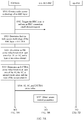
- FIG. 5A and FIG. 5B are a first interaction flowchart of a communication method according to this application.
- a first cause value is generated by a 5GS NAS and is sent to E-UTRA RRC.
- a specific execution process is as follows: S501:
- the 5GS NAS obtains a radio access technology of an RRC layer.
- a terminal has performed cell selection or cell reselection, and camps on a cell.
- the radio access technology of the RRC layer is a radio access technology used by the cell on which the terminal camps. For example, if the terminal camps on an E-UTRA cell, the radio access technology of the RRC layer is E-UTRA.
- the 5GS NAS is already in a working state, so that an RAN accessed by the terminal is an NG-RAN.
- the NG-RAN can provide two radio access technologies: NR and E-UTRA. Therefore, the 5GS NAS can learn that the radio access technology corresponding to the RRC layer is NR or E-UTRA. If a function of the 5GS NAS includes providing different parameters (for example, cause values) for NR RRC and E-UTRA RRC, the 5GS NAS needs to obtain whether the radio access technology of the RRC layer is NR or E-UTRA.
- the 5GS NAS does not need to further obtain whether the radio access technology of the RRC layer is NR or E-UTRA.
- S502 The 5GS NAS sends a request to the RRC layer, to trigger the RRC layer to establish an RRC connection.
- S503 The 5GS NAS determines that the radio access technology of the RRC layer is E-UTRA.
- the 5GS NAS determines an NR cause value (a second cause value) based on at least one of an AI, an AC, or a type of an access attempt.
- the 5GS NAS may determine the NR cause value according to the specific method in the embodiment shown in FIG. 4 .
- the 5GS NAS determines the second cause value according to Table 1.
- the 5GS NAS determines an E-UTRA cause value (the first cause value) based on at least one of the AI, the AC, the second cause value, or the type of the access attempt.
- the 5GS NAS may determine the E-UTRA cause value according to the specific method in the embodiment shown in FIG. 4 .
- the 5GS NAS determines the first cause value according to Table 2, Table 2-1, Table 3, or Table 3-1. It should be noted that S504 is an optional step. For example, if the 5GS NAS determines the first cause value based only on the AI and the AC, S504 does not need to be performed.
- the 5GS NAS sends the AI, the AC, and the E-UTRA cause value to an E-UTRA RRC layer.
- the E-UTRA RRC layer reads system information (System Information) of the camped cell, and obtains access control parameters in the system information.
- System Information System Information
- the access control parameters include an access ratio and a barring time that are related to the AC, and a bitmap (Bitmap) related to the AI.
- Bitmap bitmap
- the E-UTRA RRC layer determines, based on the AI, the AC, and the access control parameters, whether the cell is in a barred state (barred). If the cell is in the barred state, S509 is performed. If the cell is not in the barred state, S510 is performed.
- the E-UTRA RRC layer sends, to the 5GS NAS, indication information used to indicate NAS layer access barring.
- the E-UTRA RRC layer sends an RRC message to an ng-eNB.
- the RRC message is referred to as a message 3 (Message3, MSG3).
- the MSG3 carries the E-UTRA cause value, used to indicate, to the ng-eNB, a cause of initiating connection establishment or resume by the terminal.
- the ng-eNB receives the MSG3 and obtains the E-UTRA cause value in the MSG3.
- the ng-eNB determines whether access of the terminal is allowed, and returns a message 4 (Message4, MSG4). If the access is allowed, the MSG4 carries an RRC message indicating that the access is allowed, for example, the RRC message may be RRC connection setup or RRC connection resume.
- the MSG4 carries an RRC message indicating rejection, for example, the RRC message may be RRC connection reject or RRC connection resume reject.
- the ng-eNB sends the E-UTRA cause value to a network element (for example, an AMF) of a 5GC, to assist the 5GC in performing access control for the terminal.
- a network element for example, an AMF
- FIG. 6A and FIG. 6B are a second interaction flowchart of a communication method according to this application.
- a first cause value is generated by a 5GS NAS and is sent to E-UTRA RRC.
- a specific execution process is as follows:
- the 5GS NAS may determine the NR cause value according to the specific method in the embodiment shown in FIG. 4 .
- the 5GS NAS determines the second cause value according to Table 1.
- the 5GS NAS sends the AI, the AC, and the NR cause value to an E-UTRA RRC layer.
- S604 is an optional step. For example, if the E-UTRA RRC layer does not need to use the NR cause value to determine the first cause value, S504 does not need to be performed. In addition, in this step, the 5GS NAS does not need to send the NR cause value to the E-UTRA RRC layer either.
- the E-UTRA RRC layer reads system information (System Information) of the camped cell, and obtains access control parameters in the system information.
- System Information System Information
- the access control parameters include an access ratio and a barring time that are related to the AC, and a bitmap (Bitmap) related to the AI.
- Bitmap bitmap
- the E-UTRA RRC layer determines, based on the AI, the AC, and the access control parameters, whether the cell is in a barred state (barred). If the cell is in the barred state, S608 is performed. If the cell is not in the barred state, S609 and S610 are performed.
- the E-UTRA RRC layer sends, to the 5GS NAS, indication information used to indicate NAS layer access barring.
- step S609 The E-UTRA RRC layer determines an E-UTRA cause value based on at least one of the AI, the AC, the NR cause value, or the type of the access attempt.
- step S609 may be performed between step S605 and step S607.
- the E-UTRA RRC layer may determine the E-UTRA cause value according to the specific method in the embodiment shown in FIG. 4 .
- the E-UTRA RRC determines the first cause value according to Table 2, Table 2-1, Table 3, or Table 3-1.
- the E-UTRA RRC layer sends an RRC message to an ng-eNB.
- the RRC message is referred to as an MSG3.
- the MSG3 carries the E-UTRA cause value, used to indicate, to the ng-eNB, a cause of initiating RRC connection establishment or resume by the terminal.
- the ng-eNB receives the MSG3 and obtains the E-UTRA cause value in the MSG3.
- the ng-eNB determines whether access of the terminal is allowed, and returns an MSG4.
- the MSG4 carries an RRC message indicating that the access is allowed, for example, the RRC message may be RRC connection setup or RRC connection resume.
- the MSG4 carries an RRC message indicating rejection, for example, the RRC message may be RRC connection reject or RRC connection resume reject.
- the ng-eNB sends the E-UTRA cause value to a network element (for example, an AMF) of a 5GC, to assist the 5GC in performing access control for the terminal.
- a network element for example, an AMF
- the following describes a process in which the terminal accesses the 5GC through a gNB.
- FIG. 7 is a third interaction flowchart of a communication method according to this application.
- a specific process in which a terminal accesses a 5GC through a gNB is as follows: S701:
- a 5GS NAS obtains a radio access technology of an RRC layer.
- the terminal Before this step, the terminal has performed cell selection or cell reselection, and camps on a cell.
- the radio access technology of the RRC layer is a radio access technology used by the cell on which the terminal camps. For example, if the terminal camps on an E-UTRA cell, the radio access technology of the RRC layer is E-UTRA.
- the 5GS NAS is already in a working state, so that an RAN accessed by the terminal is an NG-RAN.
- the NG-RAN can provide two radio access technologies: NR and E-UTRA. Therefore, the 5GS NAS can learn that the radio access technology corresponding to the RRC layer is NR or E-UTRA. If a function of the 5GS NAS includes providing different parameters (for example, cause values) for NR RRC and E-UTRA RRC, the 5GS NAS needs to obtain whether the radio access technology of the RRC layer is NR or E-UTRA.
- the 5GS NAS does not need to further obtain whether the radio access technology of the RRC layer is NR or E-UTRA.
- the 5GS NAS sends a request to the RRC layer, to trigger the RRC layer to perform RRC connection establishment, RRC connection resume, or RRC connection reestablishment.
- the 5GS NAS determines an NR cause value based on at least one of an AI, an AC, or a type of an access attempt. For example, the 5GS NAS determines a second cause value according to Table 1.
- the 5GS NAS may determine the NR cause value according to the specific method in the embodiment shown in FIG. 4 .
- the 5GS NAS sends the AI, the AC, and the NR cause value to an NR RRC layer.
- the NR RRC layer reads system information (System Information) of the camped cell, and obtains access control parameters in the system information.
- System Information System Information
- the access control parameters include an access ratio and a barring time that are related to the AC, and a bitmap (Bitmap) related to the AI.
- Bitmap bitmap
- S706 The NR RRC layer determines, based on the AI, the AC, and the access control parameters, whether the cell is in a barred state (barred). If the cell is in the barred state, S707 is performed. If the cell is not in the barred state, S708 and S709 are performed.
- S707 The NR RRC layer sends, to the 5GS NAS, indication information used to indicate NAS layer access barring.
- the RRC message is referred to as an MSG3.
- the MSG3 carries the NR cause value, used to indicate, to the gNB, a cause of initiating connection establishment or resume by the terminal.
- the gNB receives the MSG3 and obtains the NR cause value in the MSG3.
- S710 The gNB determines whether access of the terminal is allowed, and returns an MSG4.
- the MSG4 carries an RRC message indicating that the access is allowed, for example, the RRC message may be RRC connection setup or RRC connection resume.
- the MSG4 carries an RRC message indicating rejection, for example, the RRC message may be RRC connection reject or RRC connection resume reject.
- the gNB sends the NR cause value to a network element (for example, an AMF) of the 5GC, to assist the 5GC in performing access control for the terminal.
- a network element for example, an AMF
- the embodiments shown in FIG. 5A and FIG. 5B , FIG. 6A and FIG. 6B , and FIG. 7 may be separately implemented in combination with the technical solution shown in FIG. 4 .
- the 5GS NAS may determine the NR cause value and the E-UTRA cause value by using the method shown in FIG. 4 .
- the 5GS NAS may determine the NAS cause value by using the method shown in FIG. 4
- the E-UTRA RRC layer may determine the E-UTRA cause value by using the method shown in FIG. 4 .
- different solutions may also be combined for implementation.
- the 5GS NAS may determine the first cause value based only on the AI or the AC, or the 5GS NAS may determine the first cause value based on both the AI and the AC.
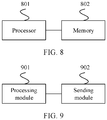
- FIG. 8 is an entity block diagram of a communications apparatus according to this application.
- the communications apparatus may be a terminal device, or may be some apparatuses in a terminal device, for example, a chip system in a terminal device.
- the chip system is configured to support a terminal device in implementing the functions in the foregoing method embodiments, for example, generating, receiving, sending, or processing the data and/or the information in the foregoing methods.
- the chip system further includes a memory.
- the memory is configured to store a program instruction and data that are necessary for a terminal device.
- the chip system includes a chip, and may further include another discrete device or circuit structure.
- the communications apparatus includes: a processor 801, where the processor 801 is configured to be coupled to a memory 802, and read and execute instructions in the memory 802, to implement:
- the processor 801 is further configured to: determine the first cause value based on a mapping relationship between the second cause value and the first cause value.
- the processor 801 is further configured to: determine the first cause value based on a mapping relationship between the AI and the first cause value. Further, the processor 801 is further configured to: determine the first cause value based on a mapping relationship between the AC and the first cause value.
- the processor 801 is further configured to: determine, at a first protocol layer, the first cause value based on the access information.
- processor 801 is further configured to:
- processor 801 is further configured to:
- the first radio access technology includes an E-UTRA technology
- the second radio access technology includes an NR technology
- the first protocol layer is a NAS
- the second protocol layer is an RRC layer.
- FIG. 9 is a structural diagram of modules of a communications apparatus according to this application. As shown in FIG. 9 , the apparatus includes:
- processing module 901 is further configured to: determine the first cause value based on a mapping relationship between the second cause value and the first cause value.
- processing module 901 is further configured to: determine the first cause value based on a mapping relationship between the AI and the first cause value.
- processing module 901 is further configured to: determine the first cause value based on a mapping relationship between the AC and the first cause value.
- processing module 901 is further configured to: determine, at a first protocol layer, the first cause value based on the access information.
- processing module 901 is further configured to:
- processing module 901 is further configured to:
- the first radio access technology includes an E-UTRA technology
- the second radio access technology includes an NR technology
- the first protocol layer is a NAS
- the second protocol layer is an RRC layer.
- the communications apparatus may further include a transceiver, configured to support the communications apparatus in sending and receiving data, signaling, or information in the foregoing method embodiments, for example, sending the first message.
- a transceiver configured to support the communications apparatus in sending and receiving data, signaling, or information in the foregoing method embodiments, for example, sending the first message.
- All or some of the foregoing embodiments may be implemented by using software, hardware, firmware, or any combination thereof.
- the embodiments may be implemented completely or partially in a form of a computer program product.
- the computer program product includes one or more computer instructions.
- the computer program instructions When the computer program instructions are loaded and executed on a computer, the procedure or functions according to the embodiments of the present invention are all or partially generated.
- the computer may be a general-purpose computer, a dedicated computer, a computer network, or other programmable apparatuses.
- the computer instructions may be stored in a computer-readable storage medium or may be transmitted from a computer-readable storage medium to another computer-readable storage medium.
- the computer instructions may be transmitted from a website, computer, server, or data center to another website, computer, server, or data center in a wired (for example, a coaxial cable, an optical fiber, or a digital subscriber line (DSL)) or wireless (for example, infrared, radio, or microwave) manner.
- the computer-readable storage medium may be any usable medium accessible by the computer, or a data storage device, such as a server or a data center, integrating one or more usable media.
- the usable medium may be a magnetic medium (for example, a floppy disk, a hard disk, or a magnetic tape), an optical medium (for example, a DVD), a semiconductor medium (for example, a solid-state drive Solid State Disk (SSD)), or the like.
- a magnetic medium for example, a floppy disk, a hard disk, or a magnetic tape
- an optical medium for example, a DVD
- a semiconductor medium for example, a solid-state drive Solid State Disk (SSD)
- this application may be provided as a method, a system, or a computer program product. Therefore, this application may use a form of hardware only embodiments, software only embodiments, or embodiments with a combination of software and hardware. Moreover, this application may use a form of a computer program product that is implemented on one or more computer-usable storage media (including but not limited to a magnetic disk memory, a CD-ROM, an optical memory, and the like) that include computer usable program code.
- a computer-usable storage media including but not limited to a magnetic disk memory, a CD-ROM, an optical memory, and the like
- These computer program instructions may be provided for a general-purpose computer, a dedicated computer, an embedded processor, or a processor of any other programmable data processing device to generate a machine, so that the instructions executed by a computer or a processor of any other programmable data processing device generate an apparatus configured to implement a specified function in one or more processes in the flowcharts and/or in one or more blocks in the block diagrams.
- These computer program instructions may also be stored in a computer-readable memory that can instruct the computer or any other programmable data processing device to work in a specific manner, so that the instructions stored in the computer-readable memory generate an artifact that includes instructions apparatus.
- the instruction apparatus implements a specified function in one or more processes in the flowcharts and/or in one or more blocks in the block diagrams.
- These computer program instructions may be loaded onto a computer or another programmable data processing device, so that a series of operations and steps are performed on the computer or the another programmable device, thereby generating computer-implemented processing. Therefore, the instructions executed on the computer or the another programmable device provide steps for implementing a specified function in one or more processes in the flowcharts and/or in one or more blocks in the block diagrams.
Landscapes
- Engineering & Computer Science (AREA)
- Computer Networks & Wireless Communication (AREA)
- Signal Processing (AREA)
- Computer Security & Cryptography (AREA)
- Mobile Radio Communication Systems (AREA)
Applications Claiming Priority (2)
| Application Number | Priority Date | Filing Date | Title |
|---|---|---|---|
| CN201810451436.0A CN110475314B (zh) | 2018-05-11 | 2018-05-11 | 通信方法及装置 |
| PCT/CN2019/086208 WO2019214683A1 (zh) | 2018-05-11 | 2019-05-09 | 通信方法及装置 |
Publications (3)
| Publication Number | Publication Date |
|---|---|
| EP3793263A1 true EP3793263A1 (de) | 2021-03-17 |
| EP3793263A4 EP3793263A4 (de) | 2021-07-14 |
| EP3793263B1 EP3793263B1 (de) | 2023-03-15 |
Family
ID=68467788
Family Applications (1)
| Application Number | Title | Priority Date | Filing Date |
|---|---|---|---|
| EP19799203.5A Active EP3793263B1 (de) | 2018-05-11 | 2019-05-09 | Kommunikationsverfahren und -vorrichtung |
Country Status (6)
| Country | Link |
|---|---|
| US (1) | US11425764B2 (de) |
| EP (1) | EP3793263B1 (de) |
| JP (1) | JP7127153B2 (de) |
| KR (1) | KR102435491B1 (de) |
| CN (2) | CN110475314B (de) |
| WO (1) | WO2019214683A1 (de) |
Families Citing this family (7)
| Publication number | Priority date | Publication date | Assignee | Title |
|---|---|---|---|---|
| CN110475314B (zh) * | 2018-05-11 | 2021-02-26 | 华为技术有限公司 | 通信方法及装置 |
| RU2763289C1 (ru) * | 2018-07-02 | 2021-12-28 | Нокиа Текнолоджиз Ой | Управление доступом для оборудования пользователя в подсоединенном режиме |
| WO2021128110A1 (zh) * | 2019-12-25 | 2021-07-01 | 华为技术有限公司 | 通信方法及装置 |
| CN113556829B (zh) * | 2020-04-23 | 2023-11-21 | 维沃移动通信有限公司 | 建立网络连接的方法和电子设备 |
| CN114584998B (zh) * | 2020-11-30 | 2024-03-22 | 中国移动通信有限公司研究院 | 无线资源控制实体的组件间的交互方法及设备 |
| CN113891391B (zh) * | 2021-09-14 | 2023-03-14 | 哲库科技(北京)有限公司 | 搜网方法、装置、终端设备及存储介质 |
| US20230362624A1 (en) * | 2022-05-04 | 2023-11-09 | Apple Inc. | User equipment aggregation |
Family Cites Families (14)
| Publication number | Priority date | Publication date | Assignee | Title |
|---|---|---|---|---|
| KR101913259B1 (ko) * | 2010-11-08 | 2018-10-30 | 엘지전자 주식회사 | 무선 통신 시스템에서 단말의 rrc 연결 방법 및 이를 위한 장치 |
| CN104770016B (zh) * | 2013-08-30 | 2019-03-08 | 华为技术有限公司 | 非接入层消息的处理方法、用户设备和网络侧设备 |
| US9860834B2 (en) * | 2013-09-13 | 2018-01-02 | Lg Electronics Inc. | Method for reselecting network node in charge of control plane |
| JP2018041996A (ja) * | 2015-01-28 | 2018-03-15 | シャープ株式会社 | 端末装置および方法 |
| WO2016144009A1 (ko) * | 2015-03-12 | 2016-09-15 | 엘지전자 주식회사 | 무선 통신 시스템에서 네트워크 트래픽을 제어하는 방법 및 단말 |
| US10790879B2 (en) * | 2016-03-28 | 2020-09-29 | Huawei Technologies Co., Ltd. | Method for routing data frame, near field communication controller, and terminal |
| CN109076437B (zh) * | 2016-03-30 | 2021-11-30 | Lg 电子株式会社 | 系统信息传输方法和基站、以及系统信息接收方法和用户设备 |
| CN109005127B (zh) * | 2017-02-03 | 2020-03-10 | 华为技术有限公司 | 一种QoS流处理方法、设备和通信系统 |
| CN109246720B (zh) * | 2017-05-11 | 2021-04-09 | 电信科学技术研究院 | 一种确定建立原因的方法和终端 |
| CN107969015A (zh) * | 2017-11-06 | 2018-04-27 | 江苏省邮电规划设计院有限责任公司 | 一种5g物联网电力数据采集终端接入控制方法 |
| CN111183665B (zh) * | 2017-11-13 | 2023-04-28 | 上海朗帛通信技术有限公司 | 一种被用于无线通信的用户设备、基站中的方法和装置 |
| CN111587606B (zh) | 2018-01-18 | 2023-09-08 | 瑞典爱立信有限公司 | 确定接入类别和/或建立原因的方法及相关装置 |
| CN110475314B (zh) * | 2018-05-11 | 2021-02-26 | 华为技术有限公司 | 通信方法及装置 |
| EP4055897B1 (de) * | 2019-11-07 | 2024-07-17 | Ofinno, LLC | Direktzugriff auf mehrere aktive protokollstapel |
-
2018
- 2018-05-11 CN CN201810451436.0A patent/CN110475314B/zh active Active
- 2018-05-11 CN CN202110247700.0A patent/CN113038574B/zh active Active
-
2019
- 2019-05-09 KR KR1020207034850A patent/KR102435491B1/ko active Active
- 2019-05-09 EP EP19799203.5A patent/EP3793263B1/de active Active
- 2019-05-09 WO PCT/CN2019/086208 patent/WO2019214683A1/zh not_active Ceased
- 2019-05-09 JP JP2020563718A patent/JP7127153B2/ja active Active
-
2020
- 2020-11-10 US US17/094,266 patent/US11425764B2/en active Active
Also Published As
| Publication number | Publication date |
|---|---|
| JP7127153B2 (ja) | 2022-08-29 |
| CN110475314A (zh) | 2019-11-19 |
| EP3793263A4 (de) | 2021-07-14 |
| CN113038574B (zh) | 2022-05-24 |
| US11425764B2 (en) | 2022-08-23 |
| WO2019214683A1 (zh) | 2019-11-14 |
| KR102435491B1 (ko) | 2022-08-24 |
| US20210058986A1 (en) | 2021-02-25 |
| CN110475314B (zh) | 2021-02-26 |
| KR20210002717A (ko) | 2021-01-08 |
| EP3793263B1 (de) | 2023-03-15 |
| CN113038574A (zh) | 2021-06-25 |
| JP2021522754A (ja) | 2021-08-30 |
Similar Documents
| Publication | Publication Date | Title |
|---|---|---|
| EP3793263B1 (de) | Kommunikationsverfahren und -vorrichtung | |
| US11032872B2 (en) | Apparatus and method for deleting session context | |
| EP3637943A1 (de) | Sitzungsverarbeitungsverfahren und -vorrichtung | |
| EP3820192A1 (de) | Kommunikationsverfahren, zugangsnetzwerkvorrichtung und endgerätevorrichtung | |
| EP3972332A1 (de) | Verfahren und vorrichtung zur überlastregelung | |
| EP3941118B1 (de) | Verfahren zur auswahl des zugangsnetztyps und vorrichtung | |
| EP3664516B1 (de) | Verfahren und vorrichtung zur steuerung der eingeschränkten ue-fähigkeit und computerspeichermedium | |
| EP3751899A1 (de) | Verfahren und vorrichtung zur bestimmung des ssc-modus | |
| WO2020135850A1 (zh) | 通信方法和装置 | |
| CN113676896A (zh) | 通信方法及相关设备 | |
| EP4093073A1 (de) | Ims-notdienstzustandsanzeigeverfahren und -vorrichtung | |
| EP3681182B1 (de) | Verfahren, gerät und vorrichtung zum bestimmen des zustands eines endgerätes | |
| EP3648512A1 (de) | Verfahren zur sitzungsverarbeitung in der drahtlosen kommunikation und endgerät | |
| EP4615022A2 (de) | Kommunikationsverfahren und -vorrichtungen | |
| WO2016177106A1 (zh) | 专用核心网的选择方法和装置 | |
| JP2023537739A (ja) | ネットワークの移行方法、端末及びネットワーク側機器 | |
| JP2020520187A (ja) | 確立理由を決定するための方法および端末 | |
| EP3800950A1 (de) | Verfahren und vorrichtung zur verwaltung von benutzerdaten | |
| EP3823387A1 (de) | Informationsanzeigeverfahren und -vorrichtung | |
| US20220303871A1 (en) | Access Barring for Radio Access Network Slicing | |
| EP3952598A1 (de) | Verwaltungsverfahren und vorrichtung für endgerät | |
| CN116420423A (zh) | 通信方法、装置和系统 | |
| CN115568010A (zh) | 公共陆地网络的优化方法、装置、用户设备及存储介质 | |
| CN117377065A (zh) | 无线通信方法、设备及存储介质 | |
| EP4550855A1 (de) | Messkonfigurationsverfahren, zugangsnetzwerkvorrichtung und endgerätevorrichtung |
Legal Events
| Date | Code | Title | Description |
|---|---|---|---|
| STAA | Information on the status of an ep patent application or granted ep patent |
Free format text: STATUS: THE INTERNATIONAL PUBLICATION HAS BEEN MADE |
|
| PUAI | Public reference made under article 153(3) epc to a published international application that has entered the european phase |
Free format text: ORIGINAL CODE: 0009012 |
|
| STAA | Information on the status of an ep patent application or granted ep patent |
Free format text: STATUS: REQUEST FOR EXAMINATION WAS MADE |
|
| 17P | Request for examination filed |
Effective date: 20201211 |
|
| AK | Designated contracting states |
Kind code of ref document: A1 Designated state(s): AL AT BE BG CH CY CZ DE DK EE ES FI FR GB GR HR HU IE IS IT LI LT LU LV MC MK MT NL NO PL PT RO RS SE SI SK SM TR |
|
| AX | Request for extension of the european patent |
Extension state: BA ME |
|
| A4 | Supplementary search report drawn up and despatched |
Effective date: 20210615 |
|
| RIC1 | Information provided on ipc code assigned before grant |
Ipc: H04W 48/16 20090101AFI20210609BHEP Ipc: H04W 76/10 20180101ALI20210609BHEP Ipc: H04W 76/27 20180101ALI20210609BHEP |
|
| DAV | Request for validation of the european patent (deleted) | ||
| DAX | Request for extension of the european patent (deleted) | ||
| STAA | Information on the status of an ep patent application or granted ep patent |
Free format text: STATUS: EXAMINATION IS IN PROGRESS |
|
| 17Q | First examination report despatched |
Effective date: 20220518 |
|
| GRAP | Despatch of communication of intention to grant a patent |
Free format text: ORIGINAL CODE: EPIDOSNIGR1 |
|
| STAA | Information on the status of an ep patent application or granted ep patent |
Free format text: STATUS: GRANT OF PATENT IS INTENDED |
|
| RIC1 | Information provided on ipc code assigned before grant |
Ipc: H04W 88/06 20090101ALN20220920BHEP Ipc: H04W 76/16 20180101ALN20220920BHEP Ipc: H04W 48/16 20090101AFI20220920BHEP |
|
| INTG | Intention to grant announced |
Effective date: 20221007 |
|
| GRAS | Grant fee paid |
Free format text: ORIGINAL CODE: EPIDOSNIGR3 |
|
| GRAA | (expected) grant |
Free format text: ORIGINAL CODE: 0009210 |
|
| STAA | Information on the status of an ep patent application or granted ep patent |
Free format text: STATUS: THE PATENT HAS BEEN GRANTED |
|
| AK | Designated contracting states |
Kind code of ref document: B1 Designated state(s): AL AT BE BG CH CY CZ DE DK EE ES FI FR GB GR HR HU IE IS IT LI LT LU LV MC MK MT NL NO PL PT RO RS SE SI SK SM TR |
|
| REG | Reference to a national code |
Ref country code: CH Ref legal event code: EP Ref country code: GB Ref legal event code: FG4D |
|
| REG | Reference to a national code |
Ref country code: NL Ref legal event code: FP |
|
| REG | Reference to a national code |
Ref country code: DE Ref legal event code: R096 Ref document number: 602019026475 Country of ref document: DE |
|
| REG | Reference to a national code |
Ref country code: IE Ref legal event code: FG4D |
|
| REG | Reference to a national code |
Ref country code: AT Ref legal event code: REF Ref document number: 1554678 Country of ref document: AT Kind code of ref document: T Effective date: 20230415 |
|
| P01 | Opt-out of the competence of the unified patent court (upc) registered |
Effective date: 20230524 |
|
| REG | Reference to a national code |
Ref country code: LT Ref legal event code: MG9D |
|
| PG25 | Lapsed in a contracting state [announced via postgrant information from national office to epo] |
Ref country code: RS Free format text: LAPSE BECAUSE OF FAILURE TO SUBMIT A TRANSLATION OF THE DESCRIPTION OR TO PAY THE FEE WITHIN THE PRESCRIBED TIME-LIMIT Effective date: 20230315 Ref country code: NO Free format text: LAPSE BECAUSE OF FAILURE TO SUBMIT A TRANSLATION OF THE DESCRIPTION OR TO PAY THE FEE WITHIN THE PRESCRIBED TIME-LIMIT Effective date: 20230615 Ref country code: LV Free format text: LAPSE BECAUSE OF FAILURE TO SUBMIT A TRANSLATION OF THE DESCRIPTION OR TO PAY THE FEE WITHIN THE PRESCRIBED TIME-LIMIT Effective date: 20230315 Ref country code: LT Free format text: LAPSE BECAUSE OF FAILURE TO SUBMIT A TRANSLATION OF THE DESCRIPTION OR TO PAY THE FEE WITHIN THE PRESCRIBED TIME-LIMIT Effective date: 20230315 Ref country code: HR Free format text: LAPSE BECAUSE OF FAILURE TO SUBMIT A TRANSLATION OF THE DESCRIPTION OR TO PAY THE FEE WITHIN THE PRESCRIBED TIME-LIMIT Effective date: 20230315 |
|
| REG | Reference to a national code |
Ref country code: AT Ref legal event code: MK05 Ref document number: 1554678 Country of ref document: AT Kind code of ref document: T Effective date: 20230315 |
|
| PG25 | Lapsed in a contracting state [announced via postgrant information from national office to epo] |
Ref country code: SE Free format text: LAPSE BECAUSE OF FAILURE TO SUBMIT A TRANSLATION OF THE DESCRIPTION OR TO PAY THE FEE WITHIN THE PRESCRIBED TIME-LIMIT Effective date: 20230315 Ref country code: GR Free format text: LAPSE BECAUSE OF FAILURE TO SUBMIT A TRANSLATION OF THE DESCRIPTION OR TO PAY THE FEE WITHIN THE PRESCRIBED TIME-LIMIT Effective date: 20230616 Ref country code: FI Free format text: LAPSE BECAUSE OF FAILURE TO SUBMIT A TRANSLATION OF THE DESCRIPTION OR TO PAY THE FEE WITHIN THE PRESCRIBED TIME-LIMIT Effective date: 20230315 |
|
| PG25 | Lapsed in a contracting state [announced via postgrant information from national office to epo] |
Ref country code: SM Free format text: LAPSE BECAUSE OF FAILURE TO SUBMIT A TRANSLATION OF THE DESCRIPTION OR TO PAY THE FEE WITHIN THE PRESCRIBED TIME-LIMIT Effective date: 20230315 Ref country code: RO Free format text: LAPSE BECAUSE OF FAILURE TO SUBMIT A TRANSLATION OF THE DESCRIPTION OR TO PAY THE FEE WITHIN THE PRESCRIBED TIME-LIMIT Effective date: 20230315 Ref country code: PT Free format text: LAPSE BECAUSE OF FAILURE TO SUBMIT A TRANSLATION OF THE DESCRIPTION OR TO PAY THE FEE WITHIN THE PRESCRIBED TIME-LIMIT Effective date: 20230717 Ref country code: ES Free format text: LAPSE BECAUSE OF FAILURE TO SUBMIT A TRANSLATION OF THE DESCRIPTION OR TO PAY THE FEE WITHIN THE PRESCRIBED TIME-LIMIT Effective date: 20230315 Ref country code: EE Free format text: LAPSE BECAUSE OF FAILURE TO SUBMIT A TRANSLATION OF THE DESCRIPTION OR TO PAY THE FEE WITHIN THE PRESCRIBED TIME-LIMIT Effective date: 20230315 Ref country code: CZ Free format text: LAPSE BECAUSE OF FAILURE TO SUBMIT A TRANSLATION OF THE DESCRIPTION OR TO PAY THE FEE WITHIN THE PRESCRIBED TIME-LIMIT Effective date: 20230315 Ref country code: AT Free format text: LAPSE BECAUSE OF FAILURE TO SUBMIT A TRANSLATION OF THE DESCRIPTION OR TO PAY THE FEE WITHIN THE PRESCRIBED TIME-LIMIT Effective date: 20230315 |
|
| PG25 | Lapsed in a contracting state [announced via postgrant information from national office to epo] |
Ref country code: SK Free format text: LAPSE BECAUSE OF FAILURE TO SUBMIT A TRANSLATION OF THE DESCRIPTION OR TO PAY THE FEE WITHIN THE PRESCRIBED TIME-LIMIT Effective date: 20230315 Ref country code: PL Free format text: LAPSE BECAUSE OF FAILURE TO SUBMIT A TRANSLATION OF THE DESCRIPTION OR TO PAY THE FEE WITHIN THE PRESCRIBED TIME-LIMIT Effective date: 20230315 Ref country code: IS Free format text: LAPSE BECAUSE OF FAILURE TO SUBMIT A TRANSLATION OF THE DESCRIPTION OR TO PAY THE FEE WITHIN THE PRESCRIBED TIME-LIMIT Effective date: 20230715 |
|
| REG | Reference to a national code |
Ref country code: DE Ref legal event code: R097 Ref document number: 602019026475 Country of ref document: DE |
|
| REG | Reference to a national code |
Ref country code: CH Ref legal event code: PL |
|
| PG25 | Lapsed in a contracting state [announced via postgrant information from national office to epo] |
Ref country code: MC Free format text: LAPSE BECAUSE OF FAILURE TO SUBMIT A TRANSLATION OF THE DESCRIPTION OR TO PAY THE FEE WITHIN THE PRESCRIBED TIME-LIMIT Effective date: 20230315 |
|
| PLBE | No opposition filed within time limit |
Free format text: ORIGINAL CODE: 0009261 |
|
| STAA | Information on the status of an ep patent application or granted ep patent |
Free format text: STATUS: NO OPPOSITION FILED WITHIN TIME LIMIT |
|
| REG | Reference to a national code |
Ref country code: BE Ref legal event code: MM Effective date: 20230531 |
|
| PG25 | Lapsed in a contracting state [announced via postgrant information from national office to epo] |
Ref country code: SI Free format text: LAPSE BECAUSE OF FAILURE TO SUBMIT A TRANSLATION OF THE DESCRIPTION OR TO PAY THE FEE WITHIN THE PRESCRIBED TIME-LIMIT Effective date: 20230315 Ref country code: MC Free format text: LAPSE BECAUSE OF FAILURE TO SUBMIT A TRANSLATION OF THE DESCRIPTION OR TO PAY THE FEE WITHIN THE PRESCRIBED TIME-LIMIT Effective date: 20230315 Ref country code: LU Free format text: LAPSE BECAUSE OF NON-PAYMENT OF DUE FEES Effective date: 20230509 Ref country code: LI Free format text: LAPSE BECAUSE OF NON-PAYMENT OF DUE FEES Effective date: 20230531 Ref country code: DK Free format text: LAPSE BECAUSE OF FAILURE TO SUBMIT A TRANSLATION OF THE DESCRIPTION OR TO PAY THE FEE WITHIN THE PRESCRIBED TIME-LIMIT Effective date: 20230315 Ref country code: CH Free format text: LAPSE BECAUSE OF NON-PAYMENT OF DUE FEES Effective date: 20230531 |
|
| 26N | No opposition filed |
Effective date: 20231218 |
|
| REG | Reference to a national code |
Ref country code: IE Ref legal event code: MM4A |
|
| PG25 | Lapsed in a contracting state [announced via postgrant information from national office to epo] |
Ref country code: IE Free format text: LAPSE BECAUSE OF NON-PAYMENT OF DUE FEES Effective date: 20230509 |
|
| PG25 | Lapsed in a contracting state [announced via postgrant information from national office to epo] |
Ref country code: IE Free format text: LAPSE BECAUSE OF NON-PAYMENT OF DUE FEES Effective date: 20230509 |
|
| PG25 | Lapsed in a contracting state [announced via postgrant information from national office to epo] |
Ref country code: IT Free format text: LAPSE BECAUSE OF FAILURE TO SUBMIT A TRANSLATION OF THE DESCRIPTION OR TO PAY THE FEE WITHIN THE PRESCRIBED TIME-LIMIT Effective date: 20230315 Ref country code: FR Free format text: LAPSE BECAUSE OF NON-PAYMENT OF DUE FEES Effective date: 20230515 Ref country code: BE Free format text: LAPSE BECAUSE OF NON-PAYMENT OF DUE FEES Effective date: 20230531 |
|
| PG25 | Lapsed in a contracting state [announced via postgrant information from national office to epo] |
Ref country code: BG Free format text: LAPSE BECAUSE OF FAILURE TO SUBMIT A TRANSLATION OF THE DESCRIPTION OR TO PAY THE FEE WITHIN THE PRESCRIBED TIME-LIMIT Effective date: 20230315 |
|
| PG25 | Lapsed in a contracting state [announced via postgrant information from national office to epo] |
Ref country code: BG Free format text: LAPSE BECAUSE OF FAILURE TO SUBMIT A TRANSLATION OF THE DESCRIPTION OR TO PAY THE FEE WITHIN THE PRESCRIBED TIME-LIMIT Effective date: 20230315 |
|
| PGFP | Annual fee paid to national office [announced via postgrant information from national office to epo] |
Ref country code: NL Payment date: 20250409 Year of fee payment: 7 |
|
| PGFP | Annual fee paid to national office [announced via postgrant information from national office to epo] |
Ref country code: DE Payment date: 20250402 Year of fee payment: 7 |
|
| PG25 | Lapsed in a contracting state [announced via postgrant information from national office to epo] |
Ref country code: CY Free format text: LAPSE BECAUSE OF FAILURE TO SUBMIT A TRANSLATION OF THE DESCRIPTION OR TO PAY THE FEE WITHIN THE PRESCRIBED TIME-LIMIT; INVALID AB INITIO Effective date: 20190509 |
|
| PG25 | Lapsed in a contracting state [announced via postgrant information from national office to epo] |
Ref country code: HU Free format text: LAPSE BECAUSE OF FAILURE TO SUBMIT A TRANSLATION OF THE DESCRIPTION OR TO PAY THE FEE WITHIN THE PRESCRIBED TIME-LIMIT; INVALID AB INITIO Effective date: 20190509 |
|
| PG25 | Lapsed in a contracting state [announced via postgrant information from national office to epo] |
Ref country code: TR Free format text: LAPSE BECAUSE OF FAILURE TO SUBMIT A TRANSLATION OF THE DESCRIPTION OR TO PAY THE FEE WITHIN THE PRESCRIBED TIME-LIMIT Effective date: 20230315 |
|
| PGFP | Annual fee paid to national office [announced via postgrant information from national office to epo] |
Ref country code: GB Payment date: 20260325 Year of fee payment: 8 |