EP3793272A1 - Procédé et appareil pour améliorer l'efficacité pour utilisateurs en bord de cellule et signaler des conditions de défaillance de liaison radio par porteuses composantes coopératives de liaison descendante - Google Patents
Procédé et appareil pour améliorer l'efficacité pour utilisateurs en bord de cellule et signaler des conditions de défaillance de liaison radio par porteuses composantes coopératives de liaison descendante Download PDFInfo
- Publication number
- EP3793272A1 EP3793272A1 EP20205604.0A EP20205604A EP3793272A1 EP 3793272 A1 EP3793272 A1 EP 3793272A1 EP 20205604 A EP20205604 A EP 20205604A EP 3793272 A1 EP3793272 A1 EP 3793272A1
- Authority
- EP
- European Patent Office
- Prior art keywords
- wtru
- site
- sites
- power
- enb
- Prior art date
- Legal status (The legal status is an assumption and is not a legal conclusion. Google has not performed a legal analysis and makes no representation as to the accuracy of the status listed.)
- Pending
Links
Images




Classifications
-
- H—ELECTRICITY
- H04—ELECTRIC COMMUNICATION TECHNIQUE
- H04L—TRANSMISSION OF DIGITAL INFORMATION, e.g. TELEGRAPHIC COMMUNICATION
- H04L5/00—Arrangements affording multiple use of the transmission path
- H04L5/0001—Arrangements for dividing the transmission path
- H04L5/0003—Two-dimensional division
- H04L5/0005—Time-frequency
- H04L5/0007—Time-frequency the frequencies being orthogonal, e.g. OFDM(A) or DMT
- H04L5/001—Time-frequency the frequencies being orthogonal, e.g. OFDM(A) or DMT the frequencies being arranged in component carriers
-
- H—ELECTRICITY
- H04—ELECTRIC COMMUNICATION TECHNIQUE
- H04L—TRANSMISSION OF DIGITAL INFORMATION, e.g. TELEGRAPHIC COMMUNICATION
- H04L5/00—Arrangements affording multiple use of the transmission path
- H04L5/003—Arrangements for allocating sub-channels of the transmission path
- H04L5/0032—Distributed allocation, i.e. involving a plurality of allocating devices, each making partial allocation
- H04L5/0035—Resource allocation in a cooperative multipoint environment
-
- H—ELECTRICITY
- H04—ELECTRIC COMMUNICATION TECHNIQUE
- H04L—TRANSMISSION OF DIGITAL INFORMATION, e.g. TELEGRAPHIC COMMUNICATION
- H04L5/00—Arrangements affording multiple use of the transmission path
- H04L5/003—Arrangements for allocating sub-channels of the transmission path
- H04L5/0053—Allocation of signalling, i.e. of overhead other than pilot signals
-
- H—ELECTRICITY
- H04—ELECTRIC COMMUNICATION TECHNIQUE
- H04L—TRANSMISSION OF DIGITAL INFORMATION, e.g. TELEGRAPHIC COMMUNICATION
- H04L5/00—Arrangements affording multiple use of the transmission path
- H04L5/003—Arrangements for allocating sub-channels of the transmission path
- H04L5/0058—Allocation criteria
- H04L5/0062—Avoidance of ingress interference, e.g. ham radio channels
-
- H—ELECTRICITY
- H04—ELECTRIC COMMUNICATION TECHNIQUE
- H04L—TRANSMISSION OF DIGITAL INFORMATION, e.g. TELEGRAPHIC COMMUNICATION
- H04L5/00—Arrangements affording multiple use of the transmission path
- H04L5/003—Arrangements for allocating sub-channels of the transmission path
- H04L5/0058—Allocation criteria
- H04L5/0073—Allocation arrangements that take into account other cell interferences
-
- H—ELECTRICITY
- H04—ELECTRIC COMMUNICATION TECHNIQUE
- H04W—WIRELESS COMMUNICATION NETWORKS
- H04W16/00—Network planning, e.g. coverage or traffic planning tools; Network deployment, e.g. resource partitioning or cells structures
- H04W16/02—Resource partitioning among network components, e.g. reuse partitioning
- H04W16/06—Hybrid resource partitioning, e.g. channel borrowing
- H04W16/08—Load shedding arrangements
-
- H—ELECTRICITY
- H04—ELECTRIC COMMUNICATION TECHNIQUE
- H04W—WIRELESS COMMUNICATION NETWORKS
- H04W36/00—Hand-off or reselection arrangements
- H04W36/06—Reselecting a communication resource in the serving access point
-
- H—ELECTRICITY
- H04—ELECTRIC COMMUNICATION TECHNIQUE
- H04W—WIRELESS COMMUNICATION NETWORKS
- H04W52/00—Power management, e.g. Transmission Power Control [TPC] or power classes
- H04W52/04—Transmission power control [TPC]
- H04W52/06—TPC algorithms
- H04W52/14—Separate analysis of uplink or downlink
- H04W52/146—Uplink power control
-
- H—ELECTRICITY
- H04—ELECTRIC COMMUNICATION TECHNIQUE
- H04W—WIRELESS COMMUNICATION NETWORKS
- H04W52/00—Power management, e.g. Transmission Power Control [TPC] or power classes
- H04W52/04—Transmission power control [TPC]
- H04W52/18—TPC being performed according to specific parameters
- H04W52/24—TPC being performed according to specific parameters using SIR [Signal to Interference Ratio] or other wireless path parameters
- H04W52/242—TPC being performed according to specific parameters using SIR [Signal to Interference Ratio] or other wireless path parameters taking into account path loss
-
- H—ELECTRICITY
- H04—ELECTRIC COMMUNICATION TECHNIQUE
- H04W—WIRELESS COMMUNICATION NETWORKS
- H04W52/00—Power management, e.g. Transmission Power Control [TPC] or power classes
- H04W52/04—Transmission power control [TPC]
- H04W52/30—Transmission power control [TPC] using constraints in the total amount of available transmission power
- H04W52/32—TPC of broadcast or control channels
- H04W52/325—Power control of control or pilot channels
-
- H—ELECTRICITY
- H04—ELECTRIC COMMUNICATION TECHNIQUE
- H04W—WIRELESS COMMUNICATION NETWORKS
- H04W52/00—Power management, e.g. Transmission Power Control [TPC] or power classes
- H04W52/04—Transmission power control [TPC]
- H04W52/30—Transmission power control [TPC] using constraints in the total amount of available transmission power
- H04W52/34—TPC management, i.e. sharing limited amount of power among users or channels or data types, e.g. cell loading
- H04W52/346—TPC management, i.e. sharing limited amount of power among users or channels or data types, e.g. cell loading distributing total power among users or channels
-
- H—ELECTRICITY
- H04—ELECTRIC COMMUNICATION TECHNIQUE
- H04W—WIRELESS COMMUNICATION NETWORKS
- H04W52/00—Power management, e.g. Transmission Power Control [TPC] or power classes
- H04W52/04—Transmission power control [TPC]
- H04W52/38—TPC being performed in particular situations
- H04W52/40—TPC being performed in particular situations during macro-diversity or soft handoff
-
- H—ELECTRICITY
- H04—ELECTRIC COMMUNICATION TECHNIQUE
- H04W—WIRELESS COMMUNICATION NETWORKS
- H04W72/00—Local resource management
- H04W72/04—Wireless resource allocation
- H04W72/044—Wireless resource allocation based on the type of the allocated resource
- H04W72/0453—Resources in frequency domain, e.g. a carrier in FDMA
-
- H—ELECTRICITY
- H04—ELECTRIC COMMUNICATION TECHNIQUE
- H04W—WIRELESS COMMUNICATION NETWORKS
- H04W72/00—Local resource management
- H04W72/20—Control channels or signalling for resource management
- H04W72/23—Control channels or signalling for resource management in the downlink direction of a wireless link, i.e. towards a terminal
-
- H—ELECTRICITY
- H04—ELECTRIC COMMUNICATION TECHNIQUE
- H04W—WIRELESS COMMUNICATION NETWORKS
- H04W24/00—Supervisory, monitoring or testing arrangements
- H04W24/08—Testing, supervising or monitoring using real traffic
-
- H—ELECTRICITY
- H04—ELECTRIC COMMUNICATION TECHNIQUE
- H04W—WIRELESS COMMUNICATION NETWORKS
- H04W36/00—Hand-off or reselection arrangements
- H04W36/0005—Control or signalling for completing the hand-off
- H04W36/0055—Transmission or use of information for re-establishing the radio link
- H04W36/0069—Transmission or use of information for re-establishing the radio link in case of dual connectivity, e.g. decoupled uplink/downlink
- H04W36/00692—Transmission or use of information for re-establishing the radio link in case of dual connectivity, e.g. decoupled uplink/downlink using simultaneous multiple data streams, e.g. cooperative multipoint [CoMP], carrier aggregation [CA] or multiple input multiple output [MIMO]
-
- H—ELECTRICITY
- H04—ELECTRIC COMMUNICATION TECHNIQUE
- H04W—WIRELESS COMMUNICATION NETWORKS
- H04W36/00—Hand-off or reselection arrangements
- H04W36/0005—Control or signalling for completing the hand-off
- H04W36/0083—Determination of parameters used for hand-off, e.g. generation or modification of neighbour cell lists
- H04W36/00835—Determination of neighbour cell lists
-
- H—ELECTRICITY
- H04—ELECTRIC COMMUNICATION TECHNIQUE
- H04W—WIRELESS COMMUNICATION NETWORKS
- H04W36/00—Hand-off or reselection arrangements
- H04W36/0005—Control or signalling for completing the hand-off
- H04W36/0083—Determination of parameters used for hand-off, e.g. generation or modification of neighbour cell lists
- H04W36/00837—Determination of triggering parameters for hand-off
-
- H—ELECTRICITY
- H04—ELECTRIC COMMUNICATION TECHNIQUE
- H04W—WIRELESS COMMUNICATION NETWORKS
- H04W36/00—Hand-off or reselection arrangements
- H04W36/0005—Control or signalling for completing the hand-off
- H04W36/0083—Determination of parameters used for hand-off, e.g. generation or modification of neighbour cell lists
- H04W36/0085—Hand-off measurements
-
- H—ELECTRICITY
- H04—ELECTRIC COMMUNICATION TECHNIQUE
- H04W—WIRELESS COMMUNICATION NETWORKS
- H04W52/00—Power management, e.g. Transmission Power Control [TPC] or power classes
- H04W52/04—Transmission power control [TPC]
- H04W52/06—TPC algorithms
- H04W52/14—Separate analysis of uplink or downlink
- H04W52/143—Downlink power control
-
- H—ELECTRICITY
- H04—ELECTRIC COMMUNICATION TECHNIQUE
- H04W—WIRELESS COMMUNICATION NETWORKS
- H04W52/00—Power management, e.g. Transmission Power Control [TPC] or power classes
- H04W52/04—Transmission power control [TPC]
- H04W52/18—TPC being performed according to specific parameters
- H04W52/28—TPC being performed according to specific parameters using user profile, e.g. mobile speed, priority or network state, e.g. standby, idle or non-transmission
- H04W52/281—TPC being performed according to specific parameters using user profile, e.g. mobile speed, priority or network state, e.g. standby, idle or non-transmission taking into account user or data type priority
-
- H—ELECTRICITY
- H04—ELECTRIC COMMUNICATION TECHNIQUE
- H04W—WIRELESS COMMUNICATION NETWORKS
- H04W52/00—Power management, e.g. Transmission Power Control [TPC] or power classes
- H04W52/04—Transmission power control [TPC]
- H04W52/18—TPC being performed according to specific parameters
- H04W52/28—TPC being performed according to specific parameters using user profile, e.g. mobile speed, priority or network state, e.g. standby, idle or non-transmission
- H04W52/283—Power depending on the position of the mobile
-
- H—ELECTRICITY
- H04—ELECTRIC COMMUNICATION TECHNIQUE
- H04W—WIRELESS COMMUNICATION NETWORKS
- H04W52/00—Power management, e.g. Transmission Power Control [TPC] or power classes
- H04W52/04—Transmission power control [TPC]
- H04W52/30—Transmission power control [TPC] using constraints in the total amount of available transmission power
-
- H—ELECTRICITY
- H04—ELECTRIC COMMUNICATION TECHNIQUE
- H04W—WIRELESS COMMUNICATION NETWORKS
- H04W52/00—Power management, e.g. Transmission Power Control [TPC] or power classes
- H04W52/04—Transmission power control [TPC]
- H04W52/30—Transmission power control [TPC] using constraints in the total amount of available transmission power
- H04W52/34—TPC management, i.e. sharing limited amount of power among users or channels or data types, e.g. cell loading
-
- H—ELECTRICITY
- H04—ELECTRIC COMMUNICATION TECHNIQUE
- H04W—WIRELESS COMMUNICATION NETWORKS
- H04W52/00—Power management, e.g. Transmission Power Control [TPC] or power classes
- H04W52/04—Transmission power control [TPC]
- H04W52/30—Transmission power control [TPC] using constraints in the total amount of available transmission power
- H04W52/34—TPC management, i.e. sharing limited amount of power among users or channels or data types, e.g. cell loading
- H04W52/343—TPC management, i.e. sharing limited amount of power among users or channels or data types, e.g. cell loading taking into account loading or congestion level
-
- H—ELECTRICITY
- H04—ELECTRIC COMMUNICATION TECHNIQUE
- H04W—WIRELESS COMMUNICATION NETWORKS
- H04W52/00—Power management, e.g. Transmission Power Control [TPC] or power classes
- H04W52/04—Transmission power control [TPC]
- H04W52/30—Transmission power control [TPC] using constraints in the total amount of available transmission power
- H04W52/36—Transmission power control [TPC] using constraints in the total amount of available transmission power with a discrete range or set of values, e.g. step size, ramping or offsets
- H04W52/367—Power values between minimum and maximum limits, e.g. dynamic range
-
- H—ELECTRICITY
- H04—ELECTRIC COMMUNICATION TECHNIQUE
- H04W—WIRELESS COMMUNICATION NETWORKS
- H04W72/00—Local resource management
- H04W72/20—Control channels or signalling for resource management
- H04W72/21—Control channels or signalling for resource management in the uplink direction of a wireless link, i.e. towards the network
-
- Y—GENERAL TAGGING OF NEW TECHNOLOGICAL DEVELOPMENTS; GENERAL TAGGING OF CROSS-SECTIONAL TECHNOLOGIES SPANNING OVER SEVERAL SECTIONS OF THE IPC; TECHNICAL SUBJECTS COVERED BY FORMER USPC CROSS-REFERENCE ART COLLECTIONS [XRACs] AND DIGESTS
- Y02—TECHNOLOGIES OR APPLICATIONS FOR MITIGATION OR ADAPTATION AGAINST CLIMATE CHANGE
- Y02D—CLIMATE CHANGE MITIGATION TECHNOLOGIES IN INFORMATION AND COMMUNICATION TECHNOLOGIES [ICT], I.E. INFORMATION AND COMMUNICATION TECHNOLOGIES AIMING AT THE REDUCTION OF THEIR OWN ENERGY USE
- Y02D30/00—Reducing energy consumption in communication networks
- Y02D30/70—Reducing energy consumption in communication networks in wireless communication networks
Definitions
- CA carrier aggregation
- eNB evolved Node-B
- WTRU wireless transmit/receive unit
- a wireless communication network and method are described for enhancing cell-edge performance of a wireless transmit/receive unit (WTRU).
- the WTRU may establish a connection with a plurality of sites via respective downlinks (DLs).
- Each DL may include at least one DL component carrier (CC) that operates on a frequency that is the same or different than one or more of the other DL CCs.
- the sites may manipulate their transmit power for a particular DL CC operating frequency such that the distance from a particular one of the sites to its cell boundary may become larger by increasing its transmit power on the particular DL CC operating frequency, and the distance from at least one of the other sites to its respective cell boundary may become smaller by decreasing its transmit power on the particular DL CC operating frequency.
- a coverage overlap between different CC frequencies may be created while maintaining a frequency reuse pattern of one.
- the WTRU may avoid the cell-edge of at least one CC frequency by performing a handover between different CC frequencies.
- the WTRU may achieve throughput performance improvement at the traditional cell-edge by selectively accessing multiple CCs from different sites that may not be near a cell-edge of a CC frequency.
- wireless transmit/receive unit includes but is not limited to a user equipment (WTRU), a mobile station, a fixed or mobile subscriber unit, a pager, a cellular telephone, a personal digital assistant (PDA), a computer, or any other type of user device capable of operating in a wireless environment.
- base station includes but is not limited to a Node-B, an evolved Node-B (eNB), a site controller, an access point (AP), or any other type of interfacing device capable of operating in a wireless environment.
- eNB evolved Node-B
- AP access point
- a wireless communication system supporting higher data rates and spectrum efficiency may use a DL transmission scheme that is based on an orthogonal frequency-division multiple access (OFDMA) air interface.
- OFDMA orthogonal frequency-division multiple access
- SC single-carrier
- DFT-S-OFDMA discrete Fourier transform-spread OFDMA
- PAPR peak-to-average power ratio
- OFDM orthogonal frequency division multiplexing
- each carrier may be aggregated in order to increase the maximum transmission bandwidth from 20 MHz up to 100 MHz, while supporting a flexible bandwidth arrangement feature.
- Each carrier i.e., component carrier (CC)
- CC component carrier
- CA is supported in the DL and the UL. Additionally, different CCs may have different coverage.
- CA wireless transmit/receive units
- RRC radio resource control
- An idle WTRU will access the network via a single UL and DL carrier pair.
- CA may be supported on a single evolved Node-B (eNB).
- eNB evolved Node-B
- a cell is identified by a unique evolved universal mobile telecommunications system (E-UMTS) terrestrial radio access network (E-UTRAN) cell global identity (ECGI), and the cell corresponds to the transmission of system information in one CC.
- E-UMTS evolved universal mobile telecommunications system
- E-UTRAN E-UTRAN
- ECGI cell global identity
- An anchor carrier is a carrier that provides system information, synchronization and paging for a certain cell.
- anchor carriers enable synchronization, camping, access and reliable control coverage in a heterogeneous network environment where interference coordination provides for at least one detectable (accessible) anchor carrier from a WTRU perspective.
- WTRU-specific anchor carriers may be considered to be a subset of the cell specific anchor carriers.
- a WTRU-specified anchor carrier may be used to carry multiple separate physical DL control channels (PDCCHs), each PDCCH corresponding to one CC.
- PDCCHs physical DL control channels
- the following three parameters may be signaled from higher layers to manage DL power allocation: Reference-signal-power, ⁇ A and ⁇ B . These parameters are used to determine cell specific DL reference signal (RS) energy per resource element (EPRE), the WTRU specific ratio of physical DL shared channel (PDSCH) EPRE over cell specific RS EPRE ( ⁇ A or ⁇ B ), and the cell-specific ratio ⁇ B / ⁇ A .
- the eNB may determine the DL transmit EPRE, and the WTRU may assume that DL cell-specific RS EPRE is constant across the DL system bandwidth and constant across all subframes until different cell-specific RS power information is received.
- the DL reference-signal EPRE may be derived from the DL reference-signal transmit power given by the parameter Reference-signal-power provided by higher layers.
- the DL reference-signal transmit power is defined as the linear average over the power contributions of all resource elements that carry cell-specific reference signals within the operating system bandwidth.
- the ratio of PDSCH EPRE to cell-specific RS EPRE among PDSCH resource elements (REs) for each OFDM symbol may be denoted by either ⁇ A or ⁇ B according to the OFDM symbol index which are functions of ⁇ A and ⁇ B .
- the Reference-signal-power, ⁇ A and ⁇ B parameters may be provided by RRC peer messages in a PDSCH-Config information element (IE).
- IE PDSCH-Config information element
- the WTRU may obtain the PDSCH-Config IE.
- the WTRU may retrieve the default radio bearer configuration that includes the PDSCH-Config from system information block 2 (SIB2) when camping onto a cell.
- SIB2 system information block 2
- the WTRU may use a stored default radio bearer configuration (including PDSCH-Config) to establish an initial RRC connection.
- an RRC Connection Reconfiguration message may be used by a network to provide the PDSCH-Config IE contained in a MobilityControlInfo IE to the WTRU.
- the PDSCH-Info may be provided along with physical cell ID and frequency, such that the network may control to where the WTRU may be connected during the active mode.
- the physical DL shared channel (PDSCH)-Config of a target eNB is obtained by the serving eNB via X2 signaling while preparing to perform the handover.
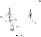
- FIG. 1 shows an example of a wireless communication system 100 including a WTRU 105 and two sites, (eNBs 110 and 115).
- the system 100 is configured such that the WTRU 105 may aggregate CC bandwidth to increase data transfer rate.
- the WTRU 105 communicates only with the eNB 110 via two separate CCs: CC 120 and CC 125.
- CQI channel quality indicator
- ACK positive acknowledgement
- NACK negative acknowledgement
- Figure 2 shows one possible wireless communication system configuration where two DL CCs may be configured. Each site transmits on a CC with a different power, (i.e., either full power or reduced power). All of the WTRUs experience an acceptable level of signal-to-interference plus noise ratio (SINR) on a given CC.
- SINR signal-to-interference plus noise ratio
- Figure 2 shows a scenario where the WTRU 105 is in the position of WTRU 1, where both CC 2 and CC3 may be accessible. If WTRU 105 is in the position of WTRU 3, both CC 1 and CC 4 may be accessible. When WTRU 105 is in the position of WTRU 2, only one of CC 1 or CC 2 is accessible.
- a network radio resource management (RRM) entity may determine whether or not a handover is to be performed to drop CC 2, in order to access CC 1 on Site 1, rather than taking full benefit of the data throughput increase by using multiple CCs from a different site.
- RRM radio resource management
- UC frequency 1 and UC frequency 2 For example, if there are two UL CC (UC) frequencies per site, UC frequency 1 and UC frequency 2, the path losses between WTRU 1 and Site 1 on each of these UL CC frequencies may be smaller than the path loss to Site 2. Similarly, for WTRU 3, the path loss to Site 2 may be more favorable. For WTRU 2, however, the UL channel quality may be different than the DL signal quality. Thus, it may be possible that the path losses on both UC frequency 1 and UC frequency 2 may be smaller to Site 1, even though the DL transmission on CC1 is received from Site 2 due to the increased transmission power on CC1 by Site 2.
- FIG. 3A shows an example communications system 300 in which one or more disclosed embodiments may be implemented.
- the communications system 300 may be a multiple access system that provides content, such as voice, data, video, messaging, broadcast, etc., to multiple wireless users.
- the communications system 300 may enable multiple wireless users to access such content through the sharing of system resources, including wireless bandwidth.
- the communications system 300 may employ one or more channel access methods, such as code division multiple access (CDMA), time division multiple access (TDMA), frequency division multiple access (FDMA), orthogonal FDMA (OFDMA), single-carrier FDMA (SC-FDMA), and the like.
- CDMA code division multiple access
- TDMA time division multiple access
- FDMA frequency division multiple access
- OFDMA orthogonal FDMA
- SC-FDMA single-carrier FDMA
- the communications system 300 may include WTRUs 302a, 302b, 302c, 302d, a radio access network (RAN) 304, a core network 306, a public switched telephone network (PSTN) 308, the Internet 310, and other networks 312, though it will be appreciated that the disclosed embodiments contemplate any number of WTRUs, base stations, networks, and/or network elements.
- Each of the WTRUs 302a, 302b, 302c, 302d may be any type of device configured to operate and/or communicate in a wireless environment.
- the WTRUs 302a, 302b, 302c, 302d may be configured to transmit and/or receive wireless signals and may include user equipment (UE), a mobile station, a fixed or mobile subscriber unit, a pager, a cellular telephone, a personal digital assistant (PDA), a smartphone, a laptop, a netbook, a personal computer, a wireless sensor, consumer electronics, and the like.
- UE user equipment
- PDA personal digital assistant
- smartphone a laptop
- netbook a personal computer
- a wireless sensor consumer electronics, and the like.
- the communications systems 300 may also include a base station 314a and a base station 314b.
- Each of the base stations 314a, 314b may be any type of device configured to wirelessly interface with at least one of the WTRUs 302a, 302b, 302c, 302d to facilitate access to one or more communication networks, such as the core network 306, the Internet 310, and/or the other networks 312.
- the base stations 314a, 314b may be a base transceiver station (BTS), a Node-B, an eNB, a Home Node-B (HNB), a Home eNB (HeNB), a site controller, an access point (AP), a wireless router, a remote radio head (RRH), and the like. While the base stations 314a, 314b are each depicted as a single element, it will be appreciated that the base stations 314a, 314b may include any number of interconnected base stations and/or network elements.
- the base station 314a may be part of the RAN 304, which may also include other base stations and/or network elements (not shown), such as a base station controller (BSC), a radio network controller (RNC), relay nodes, and the like.
- the base station 314a and/or the base station 314b may be configured to transmit and/or receive wireless signals within a particular geographic region, which may be referred to as a cell (not shown).
- the cell may further be divided into cell sectors.
- the cell associated with the base station 314a may be divided into three sectors.
- the base station 314a may include three transceivers, i.e., one for each sector of the cell.
- the base station 314a may employ multiple-input multiple-output (MIMO) technology and, therefore, may utilize multiple transceivers for each sector of the cell.
- MIMO multiple-input multiple-output
- the base stations 314a, 314b may communicate with one or more of the WTRUs 302a, 302b, 302c, 302d over an air interface 316, which may be any suitable wireless communication link (e.g., radio frequency (RF), microwave, infrared (IR), ultraviolet (UV), visible light, and the like).
- the air interface 316 may be established using any suitable radio access technology (RAT).
- RAT radio access technology
- the communications system 300 may be a multiple access system and may employ one or more channel access schemes, such as CDMA, TDMA, FDMA, OFDMA, SC-FDMA, and the like.
- the base station 314a in the RAN 304 and the WTRUs 302a, 302b, 302c may implement a radio technology such as universal mobile telecommunications system (UMTS) terrestrial radio access (UTRA), which may establish the air interface 316 using wideband CDMA (WCDMA).
- WCDMA may include communication protocols such as high-speed packet access (HSPA) and/or evolved HSPA (HSPA+).
- HSPA may include high-speed DL packet access (HSDPA) and/or high-speed UL packet access (HSUPA).
- the base station 314a and the WTRUs 302a, 302b, 302c may implement a radio technology such as evolved UTRA (E-UTRA), which may establish the air interface 316 using long term evolution (LTE) and/or LTE-Advanced (LTE-A).
- E-UTRA evolved UTRA
- LTE long term evolution
- LTE-A LTE-Advanced
- the base station 314a and the WTRUs 302a, 302b, 302c may implement radio technologies such as IEEE 802.16 (i.e., worldwide interoperability for microwave access (WiMAX)), CDMA2000, CDMA2000 1X, CDMA2000 evolution data optimized (EV-DO), Interim Standard 2000 (IS-2000), Interim Standard 95 (IS-95), Interim Standard 856 (IS-856), global system for mobile communications (GSM), enhanced data rates for GSM evolution (EDGE), GSM/EDGE RAN (GERAN), and the like.
- IEEE 802.16 i.e., worldwide interoperability for microwave access (WiMAX)
- the base station 314b in Figure 3A may be a wireless router, a Node B, a HNB, a combination of an RNC and Node-B, an eNB, a HeNB, an RRH with an associated base station, or an AP, for example, and may utilize any suitable RAT for facilitating wireless connectivity in a localized area, such as a place of business, a home, a vehicle, a campus, and the like.
- the base station 314b and the WTRUs 302c, 302d may implement a radio technology such as IEEE 802.11 to establish a wireless local area network (WLAN).
- WLAN wireless local area network
- the base station 314b and the WTRUs 302c, 302d may implement a radio technology such as IEEE 802.15 to establish a wireless personal area network (WPAN).
- the base station 314b and the WTRUs 302c, 302d may utilize a cellular-based RAT, (e.g., WCDMA, CDMA2000, GSM, LTE, LTE-A, and the like) to establish a picocell or femtocell.
- a cellular-based RAT e.g., WCDMA, CDMA2000, GSM, LTE, LTE-A, and the like
- the base station 314b may have a direct connection to the Internet 310.
- the base station 314b may not be needed to access the Internet 310 via the core network 306.
- the RAN 304 may be in communication with the core network 306, which may be any type of network configured to provide voice, data, applications, and/or voice over Internet protocol (VoIP) services to one or more of the WTRUs 302a, 302b, 302c, 302d.
- the core network 306 may provide call control, billing services, mobile location-based services, pre-paid calling, Internet connectivity, video distribution, and the like, and/or perform high-level security functions, such as user authentication.
- the RAN 304 and/or the core network 306 may be in direct or indirect communication with other RANs that employ the same RAT as the RAN 304 or a different RAT.
- the core network 306 may also be in communication with another RAN (not shown) employing a GSM radio technology.
- the core network 306 may also serve as a gateway for the WTRUs 302a, 302b, 302c, 302d to access the PSTN 308, the Internet 310, and/or other networks 312.
- the PSTN 308 may include circuit-switched telephone networks that provide plain old telephone service (POTS).
- POTS plain old telephone service
- the Internet 310 may include a global system of interconnected computer networks and devices that use common communication protocols, such as the transmission control protocol (TCP), user datagram protocol (UDP) and the Internet protocol (IP) in the TCP/IP suite.
- the networks 312 may include wired or wireless communications networks owned and/or operated by other service providers.
- the networks 312 may include another core network connected to one or more RANs, which may employ the same RAT as the RAN 304 or a different RAT.
- the WTRUs 302a, 302b, 302c, 302d in the communications system 300 may include multi-mode capabilities, i.e., the WTRUs 302a, 302b, 302c, 302d may include multiple transceivers for communicating with different wireless networks over different wireless links.
- the WTRU 302c shown in Figure 3A may be configured to communicate with the base station 314A, which may employ a cellular-based radio technology, and with the base station 314B, which may employ an IEEE 802 radio technology.
- FIG 3B shows an example WTRU 302 that may be used within the communication system 100 shown in Figure 3A .
- the WTRU 302 may include a processor 318, a transceiver 320, a transmit/receive element 322, (e.g., an antenna), a speaker/microphone 324, a keypad 326, a display/touchpad 328, a non-removable memory 330, a removable memory 332, a power source 334, a global positioning system (GPS) chipset 336, and peripherals 338.
- the WTRU 302 may include any sub-combination of the foregoing elements while remaining consistent with an embodiment.
- the processor 318 may be a general purpose processor, a special purpose processor, a conventional processor, a digital signal processor (DSP), a microprocessor, one or more microprocessors in association with a DSP core, a controller, a microcontroller, an application specific integrated circuit (ASIC), a field programmable gate array (FPGA) circuit, an integrated circuit (IC), a state machine, and the like.
- the processor 318 may perform signal coding, data processing, power control, input/output processing, and/or any other functionality that enables the WTRU 302 to operate in a wireless environment.
- the processor 318 may be coupled to the transceiver 320, which may be coupled to the transmit/receive element 322. While Figure 3B depicts the processor 318 and the transceiver 320 as separate components, the processor 318 and the transceiver 320 may be integrated together in an electronic package or chip.
- the transmit/receive element 322 may be configured to transmit signals to, or receive signals from, a base station (e.g., the base station 314a) over the air interface 316.
- a base station e.g., the base station 314a
- the transmit/receive element 322 may be an antenna configured to transmit and/or receive RF signals.
- the transmit/receive element 322 may be an emitter/detector configured to transmit and/or receive IR, UV, or visible light signals, for example.
- the transmit/receive element 322 may be configured to transmit and receive both RF and light signals.
- the transmit/receive element 322 may be configured to transmit and/or receive any combination of wireless signals.
- the WTRU 302 may include any number of transmit/receive elements 322. More specifically, the WTRU 302 may employ MIMO technology. Thus, in one embodiment, the WTRU 302 may include two or more transmit/receive elements 322 (e.g., multiple antennas) for transmitting and receiving wireless signals over the air interface 316.
- the transceiver 320 may be configured to modulate the signals that are to be transmitted by the transmit/receive element 322 and to demodulate the signals that are received by the transmit/receive element 322.
- the WTRU 302 may have multi-mode capabilities.
- the transceiver 320 may include multiple transceivers for enabling the WTRU 302 to communicate via multiple RATs, such as UTRA and IEEE 802.11, for example.
- the processor 318 of the WTRU 302 may be coupled to, and may receive user input data from, the speaker/microphone 324, the keypad 326, and/or the display/touchpad 328 (e.g., a liquid crystal display (LCD) display unit or organic light-emitting diode (OLED) display unit).
- the processor 318 may also output user data to the speaker/microphone 324, the keypad 326, and/or the display/touchpad 328.
- the processor 318 may access information from, and store data in, any type of suitable memory, such as the non-removable memory 330 and/or the removable memory 332.
- the non-removable memory 330 may include random-access memory (RAM), read-only memory (ROM), a hard disk, or any other type of memory storage device.
- the removable memory 332 may include a subscriber identity module (SIM) card, a memory stick, a secure digital (SD) memory card, and the like.
- SIM subscriber identity module
- SD secure digital
- the processor 318 may access information from, and store data in, memory that is not physically located on the WTRU 302, such as on a server or a home computer (not shown).
- Figure 3C shows an example RAN 304 and an example core network 306 that may be used within the communication system 100 shown in Figure 3A .
- the RAN 304 may employ an E-UTRA, a WCDMA or a GSM radio technology to communicate with the WTRUs 302a, 302b, 302c over the air interface 316.
- the RAN 304 may also be in communication with the core network 306.
- the RAN 304 may include eNBs 340a, 340b, 340c, though it will be appreciated that the RAN 304 may include any number of eNBs while remaining consistent with an embodiment.
- the eNBs 340a, 340b, 340c may each include one or more transceivers for communicating with the WTRUs 302a, 302b, 302c over the air interface 316.
- the eNBs 340a, 340b, 340c may implement MIMO technology.
- the eNB 340a for example, may use multiple antennas to transmit wireless signals to, and receive wireless signals from, the WTRU 302a.
- Each of the eNBs 340a, 340b, 340c may be associated with a particular cell (not shown) and may be configured to handle radio resource management decisions, handover decisions, scheduling of users in the UL and/or DL, and the like. As shown in Figure 3C , the eNBs 340a, 340b, 340c may communicate with one another over an X2 interface.
- the core network 306 shown in Figure 3C may include a mobility management gateway (MME) 342, a serving gateway (S-GW) 344, and a packet data network (PDN) gateway 346. While each of the foregoing elements are depicted as part of the core network 306, it will be appreciated that any one of these elements may be owned and/or operated by an entity other than the core network operator.
- MME mobility management gateway
- S-GW serving gateway
- PDN gateway 346 packet data network
- the MME 342 may be connected to each of the eNBs 342a, 342b, 342c in the RAN 304 via an S1 interface and may serve as a control node.
- the MME 342 may be responsible for authenticating, managing and storing contexts of users of the WTRUs 302a, 302b, 302c, bearer activation/deactivation, selecting a particular serving gateway during an initial attach of the WTRUs 302a, 302b, 302c, and the like.
- the MME 342 may also provide a control plane function for switching between the RAN 304 and other RANs (not shown) that employ other radio technologies, such as GSM or WCDMA.
- the MME 342 may be a gateway general packet radio service (GPRS) support node.
- the S-GW 344 may be connected to each of the eNBs 340a, 340b, 340c in the RAN 304 via the S1 interface.
- the S-GW 344 may generally route and forward user data packets to/from the WTRUs 302a, 302b, 302c.
- the S-GW 344 may also perform other functions, such as anchoring user planes during inter-eNB handovers, triggering paging when DL data is available for the WTRUs 302a, 302b, 302c.
- the S-GW 344 may be a serving general packet radio service (GPRS) support node (SGSN).
- GPRS general packet radio service
- the S-GW 344 may also be connected to the PDN gateway 346, which may provide the WTRUs 302a, 302b, 302c with access to packet-switched networks, such as the Internet 110, to facilitate communications between the WTRUs 302a, 302b, 302c and IP-enabled devices.
- PDN gateway 346 may provide the WTRUs 302a, 302b, 302c with access to packet-switched networks, such as the Internet 110, to facilitate communications between the WTRUs 302a, 302b, 302c and IP-enabled devices.
- the core network 306 may facilitate communications with other networks.
- the core network 306 may provide the WTRUs 302a, 302b, 302c with access to circuit-switched networks, such as the PSTN 308, to facilitate communications between the WTRUs 302a, 302b, 302c and traditional land-line communications devices.
- the core network 106 may include, or may communicate with, an IP gateway (e.g., an IP multimedia subsystem (IMS) server) that serves as an interface between the core network 306 and the PSTN 308.
- IMS IP multimedia subsystem
- the core network 306 may provide the WTRUs 302a, 302b, 302c with access to the networks 312, which may include other wired or wireless networks that are owned and/or operated by other service providers.
- certain wireless communication systems support scalable transmission bandwidths of either 1.4, 3, 5, 10, 15 or 20 MHz. These systems may operate in either frequency division duplex (FDD), time division duplex (TDD) or half-duplex FDD modes.
- FDD frequency division duplex
- TDD time division duplex
- each radio frame (10 ms) may consist of 10 equally sized sub-frames of one (1) ms each.
- Each sub-frame may consist of two equally sized timeslots of 0.5 ms each.
- the sub-carrier spacing for these systems may be 15 kHz.
- An alternative reduced sub-carrier spacing mode using 7.5 kHz is also possible.
- a resource element (RE) may correspond to one (1) sub-carrier during one (1) OFDM symbol interval.
- a DL carrier may consist of a scalable number of resource blocks (RBs), ranging from a minimum of 6 RBs up to a maximum of 100 RBs. This corresponds to an overall scalable transmission bandwidth of roughly one (1) MHz up to twenty (20) MHz. However, a set of common transmission bandwidths may be specified, (e.g., 1.4, 3, 5, 10 or 20 MHz).
- the basic time-domain unit for dynamic scheduling may be one sub-frame comprising two consecutive timeslots, (i.e., a resource-block pair). Certain sub-carriers on some OFDM symbols may be allocated to carry pilot signals in the time-frequency grid. A given number of sub-carriers at the edges of the transmission bandwidth may not be transmitted in order to comply with the spectral mask requirements.
- a WTRU may be allocated by the eNB to receive its data anywhere across the entire transmission bandwidth, e.g., an OFDMA scheme may be used.
- the DL may have an unused direct current (DC) offset sub-carrier in the center of the spectrum.
- DC direct current
- DL grants may be carried on a PDCCH.
- PDCCH coding e.g., a separate coding means that the PDCCH message for different CCs is encoded using a separate cyclic redundancy check (CRC) and a convolutional code
- CRC cyclic redundancy check
- convolutional code e.g., a separate coding means that the PDCCH message for different CCs is encoded using a separate cyclic redundancy check (CRC) and a convolutional code
- a WTRU may be used to monitor a set of PDCCH candidates for control information in every non-discontinuous reception (DRX) subframe, where monitoring implies attempting to decode each of the PDCCHs in the set according to various monitored DL control information (DCI) formats.
- DRX non-discontinuous reception
- DCI monitored DL control information
- the DCI formats a WTRU monitors may be divided into WTRU-specific search space and common search space.
- the WTRU may monitor DCI 0/1A and DCI, which may be semi-statically configured via RRC signaling, depending on the transmission mode.
- a PDCCH DL monitoring set may be defined, which comprises the DL CCs from the WTRU DL CC set on which a WTRU may be configured to receive scheduling assignments for cross-carrier scheduling.
- the WTRU may not have to perform blind decoding in DL CCs on which it is not configured to receive PDCCH, which reduces the probability of PDCCH false detection.
- the WTRU may have one RRC connection with the network.
- the addition and removal of CCs may be performed without an RRC connection HO, as long as in case of removal, the CC being removed is not a special cell.
- a special cell may be primary component carrier (PCC) or the carrier that provides the control plane signaling exchange for the WTRU.
- the CCs may exist in two states: 1) configured but deactivated; and 2) activated.
- the WTRU may not receive PDCCH or PDSCH on deactivated CCs.
- the WTRU may receive PDSCH, and PDCCH, if present. Further, the WTRU may not be used to perform CQI measurements on deactivated CCs.
- an explicit activation/deactivation procedure may not be introduced.
- the network may configure mobility measurements to support WTRU inter-site handover based on reference signal received power (RSRP) or reference signal received quality (RSRQ).
- RSRP reference signal received power
- RSRQ reference signal received quality
- the WTRU may be configured to measure neighbor cell power on event or periodic reporting basis.
- the network relies on these neighbor cell measurements from the WTRU to make decisions on when to handover a WTRU to a different site within a given CC set.
- the network configures the WTRU such that it monitors, (e.g., makes measurements on), neighbor cells/sites in supported CCs to move the WTRU onto a CC that maintains the delivered service quality in support of WTRU mobility.
- the periodic measurements or measurement events (1 ⁇ and 2 ⁇ ) may provide sufficient information to the network to select the appropriate CC that may be used to transmit data to a particular WTRU for each CC that may be used, and when such CC-specific (inter-site) handover (CSHO) occurs.
- CSHO CC-specific handover
- measurement events (1 ⁇ and 2 ⁇ ) may be applicable for a WTRU configured with CA. These measurement events may be able to identify an individual CC for inclusion in a handover.
- the WTRU data When data is sent to a WTRU from multiple sites, the WTRU data may be present at multiple sites. Generally, this creates additional strain on the backhaul if done in the same fashion as for coordinated multi-point (CoMP) transmission, where multiple transmission points/sites coordinate their transmissions.
- This coordination may take several different forms such as coordination in scheduling, jointly transmitting data to a WTRU, and the like.
- EPS evolved packet system
- RAB radio access bearer
- MAC medium access control
- data may be received at a serving eNB, and then copied and forwarded to all cooperating CCs/eNBs. This approximately doubles the backhaul loads per WTRU participating in CoMP joint transmissions involving two sites.
- the problem of cell-edge degradation due to interference limitations from neighboring cells in a frequency reuse 1 deployment may be alleviated by: 1) manipulating the locations of the cell-edges in each CC in the system; and/or 2) allowing the WTRU to receive data from multiple sites, (e.g., data may be received from Site A on carrier 1 and from Site B on carrier 2).
- the WTRU may be assigned to the site that provides the best throughput, (or other measure), for each CC that is in full aggregation of CCs, thereby creating the "fuzzy cell" concept where the notion of cell-edge does not apply as in a traditional cellular setting.
- a frequency reuse of one may be maintained.
- the WTRU may receive data on each available CC.
- the locations of the transmitting sites of the data for the WTRU may not be co-located in the system.
- the cell boundary may be determined in part by the ratio of the largest signal power from any site to the sum of the power in the other signals (interference) and noise received at a given location and in any CC.
- the signal and interference powers received may be determined in part by the pathloss, antenna gain, and transmit power from each cell to the WTRU location. The manipulation of the cell-edge locations may then be performed using several different techniques.
- the WTRU may establish a connection with a plurality of sites via respective DLs.
- the sites may include at least one of a Node-B, an eNB, a remote radio head (RRH) associated with a base station, or one of several sector transmit antennas of a Node-B or an eNB.
- Each DL may include at least one DL CC that operates on a frequency that is the same or different than one or more of the other DL CCs.
- the sites may manipulate their transmit power for a particular DL CC operating frequency, such that the distance from a particular one of the sites to its cell boundary becomes larger by increasing its transmit power on the particular operating frequency, and the distance from at least one of the other sites to its respective cell boundary becomes smaller by decreasing its transmit power on the particular operating frequency.
- a coverage overlap between different CC frequencies is created while maintaining a frequency reuse pattern of one.
- Figure 4 shows the SINR of each of two DL CCs 405 and 410 at each site.
- one CC is transmitted at a higher power than the other.
- Each of these CCs 405 and 410 may be considered a cell of its own with a different carrier frequency and potentially different coverage areas. The different coverage areas may result from differences in propagation conditions. However, certain system parameters may also be changed to intentionally change the DL coverage, such as transmit power, HO thresholds, sector antenna direction, and the like. This creates the opportunity for using CC to mitigate the DL cell-edge problem.
- the coverage area may be intentionally adjusted for different DL CCs so that there may not be a point in the system at which a WTRU may find itself at the cell-edge of every DL CC it is attached to.
- the WTRU may not be at the cell-edge in both the carrier frequencies, (e.g., when the WTRU is at the cell-edge in the one carrier, it may still have satisfactory performance in the other carrier, and when the WTRU is located near the midpoint between two eNBs, the carrier SINR may still be better than the SINR of the single carrier system).
- the sector antenna patterns may be adjusted, (e.g., beamwidth, broadside angle, or other beam pattern shaping), so that transmit power density at different angles is controlled.
- the cell-edge locations may thus be manipulated by antenna patterns in a similar fashion as when the total transmit power was adjusted, except that now there is an angular component to affect on the location of the cell-edges, (i.e., changing the total power may change the power density in all departure angles by the same amount, whereas changing the antenna patterns may selectively change the transmit power density at different departure angles).
- a 3-sector pattern having 120 degrees per sector may be maintained within each carrier frequency, but one set of sector antennas may be rotated relative to the other.
- the ellipses 505 may indicate sectors in the frequency of CC 405 in Figure 4
- the ellipses 510 may indicate sectors in the frequency of CC 410 in Figure 4 .
- the center of the sector beam in one CC frequency may be placed directly on top of the sector cell-edge in the other CC frequency. If the WTRU is able to connect to two CCs, it may effectively eliminate the perceived cell-edge in a substantial part of the system.
- the cell-edge locations may be configured to have large separations, (i.e., the cell-edge locations in one CC may be geographically separated from the cell-edge locations in at least one or more of the other CCs in the aggregation).
- each site may support all available CCs, whereby different CCs may use different transmit powers, as well as antenna patterns, so that the corresponding coverage may also be different per CC, (i.e., the cell-boundaries across all CCs may not be co-located).
- site numbers ⁇ 1, 2, 3, ... ⁇ may be assigned.
- a power usage pattern may be defined where all even numbered sites transmit at power P1 and all odd numbered sites transmit at power P2.
- a power usage pattern may be defined where all even numbered sites transmit at power P3 and all odd numbered sites transmit at power P4.
- Antenna usage patterns may also be defined.
- an antenna usage pattern may be defined where all even numbered sites transmit with pattern A1 and all odd numbered sites transmit with pattern A2.
- an antenna usage pattern may be defined where all even numbered sites transmit with pattern A3 and all odd numbered sites transmit with pattern A4.
- antenna gain may be larger pointing North in CC1 and pointing East in CC2
- antenna gain may be larger pointing South in CC1 and pointing West in CC2.
- the set of CCs used by a particular WTRU may originate from different transmission sites or cells.
- the WTRU may be assigned to receive data from the transmission point that has the best signal quality, (e.g., signal-to-interference ratio (SIR)) for that CC frequency).
- SIR signal-to-interference ratio
- the assigned CCs may originate from multiple transmission sites, (e.g., CC1 and CC2 from Site A, CC3 from Site B, and CC4 from site C).
- DL carrier frequency dlF1, dlF2...dlFn DL carrier frequency dlF1, dlF2...dlFn
- UL carrier frequency ulF1, ulF2...ulFn DL cooperative CCs DL-CCC1, DL-CCC2...DL-CCCn
- UL CCs UL-CC1, UL-CC2...UL-CCn sites S1, S2....Sn.
- a CC-specific handover (CSHO) mechanism may be implemented in addition to individual CC activation/deactivation and CC management. CSHO may also be implemented when a special cell has been changed. Alternatively, an individual CC activation or CC deactivation may be used instead of an RRC reconfiguration procedure. For example, as the WTRU moves about, it will encounter CC-specific cell edges at different locations. The quality (e.g., SINR) of only a subset of the CCs assigned to the WTRU will drop to a point that the transmitting site for that CC should be switched to another site to maintain a desired reception quality.
- SINR Quality of only a subset of the CCs assigned to the WTRU will drop to a point that the transmitting site for that CC should be switched to another site to maintain a desired reception quality.
- WTRU may be configured to report neighbor cells/sites in all CCs (or a subset of CCs) that are part of the candidate set of CCs involved in a CC cooperation network. This may be implemented via an explicit modification of a monitored neighbor cell list, or via an implicit handling of cells detected by the WTRU by adding an undesired cell to a black list, or a configuration of a measurement on a specific CC of a network to ensure selection of a CC in the CC cooperation network to maintain the delivered service quality in support of WTRU mobility.
- the network may have sufficient information to determine the appropriate site that may be used to transmit data to a particular WTRU for each CC that may be used, and determine when CSHO may occur.
- This scenario may be fundamentally different from the usual handover, in that the WTRU remains in continuous contact with all sites, except for those being handed over to a new site, (if the WTRU does not already have a connection to it via a different CC), or when all of the CC connections from a site to the WTRU is terminated. Furthermore, the WTRU may remain in continuous connection with at least one site at all times, (i.e., the handover may be seamless).
- Measurements performed on each CC may be scheduled, or triggers set up, such that the measurement overhead to support CSHO may be reduced based on the time when a CC-specific inter-site handover is beneficial in one CC, as well as when CSHO to another CC is not likely to be beneficial. Therefore, a method to define measurements independently on each CC may be defined so that measurements may be performed and signaled when they may actually be needed to support a CSHO.
- CSHO when the SINR in a particular CC drops below a threshold, (or the particular CC is otherwise determined to be a candidate for CSHO), a measurement to support the CSHO only in the particular CC is performed and reported to a network, and measurements in the other CCs may not be triggered unless they also are candidates for CSHO.
- CSHO in which a new site is not being added may already be connected to the site which is the target of the handover.
- the data flow may be split so that complete copies of the WTRU's data is not sent to all of the sites involved in the CC cooperation transmission. For example, the data flow may be split before reaching any of the sites, such that only the data ultimately transmitted from a particular site is present at that site. Data transmitted from Site A may not need to be present at any site other than Site A. This potentially yields the most efficient solution to the data flow from a backhaul bottleneck point of view.
- a full copy of the WTRU's data sent to a particular site (i.e., an anchor site, camping site, primary site, and the like), and then the particular site may only send a portion of the data to the remaining sites that will transmit data to the WTRU.
- a complete data flow is sent to Site A. From Site A, a portion of the data is sent to Site B. Site B transmits all such data to the WTRU and Site A transmits only the portion of data not previously sent to Site B. Site A may be chosen to be the site that will transmit the most data to minimize the total backhaul load. CoMP joint transmission techniques may also be used on the carrier used by Site B, since both sites may have this data.
- the CC cooperation concept may be a possible low cost alternative to CoMP. However, they both may be deployed together and benefit from certain synergies. Depending on the suitability of CoMP, such techniques may be applied within one or more CCs. For example, if a WTRU is connected to two sites using different CCs, (Site 1 for CC1 and Site 2 for CC2), and if Site 1 is the primary camping site, the DL data from Site 2 may be split from Site 1. If the signal on CC2 from Site 2 is a candidate for CoMP techniques, CoMP may be employed with no increase in backhaul loads, (e.g., CC2 from Site 1 may be used to improve the reliability of the data transmission from Site 2 under a CoMP framework).
- the CC cooperation takes place between Site 1 and Site 2, there is no need to copy the data from Site 2 to Site 1 again, since that data was originally forwarded from Site 1. If the CC cooperation takes place between Site 2 and one or more sites other than Site 1, (e.g., Site 3), then the data may be directly forwarded from Site 1 to Sites 2 and 3, or the data may be forwarded from Site 2 to Site 3 under a CoMP framework.
- While the CC cooperation network configuration may be deployed independent of CoMP, the CoMP set selection, (either the measurement set or the cooperating set, and the like), decisions may be influenced by the CCC set, on a condition that the camping site already has a full WTRU data set.
- An additional input to a CoMP set determining algorithm may be defined to permit CoMP set decisions to be performed with the knowledge of the CCC configuration.
- CC1 may be determined to be a CoMP candidate, and Sites 2 and 3 may both be satisfactory candidates to participate in CoMP transmissions.
- the choice of adding Site 2 or Site 3 to the CoMP set may normally not consider the CCC configuration, and either site may be chosen.
- Site 3 may be chosen rather than Site 2.
- Site 3 By creating the interface from the CCC configuration to the CoMP set determination algorithm, a better selection may be made.
- the configuration of a network with the CCC feature may be performed and adaptively changed by exchanging certain information among the cooperating sites.
- the cooperating sites may try to adjust the transmission parameters.
- the transmission parameters may be determined in a central controller after collecting all possible information from the cooperating transmission points.
- the central controller may be responsible for the configuration of the transmission parameters of a cluster of transmission points.
- the transmission parameters may be autonomously determined by the transmission points by using the information exchanged among these points. In this case, the decision processes used in the sites may go through several iterations until a stable set of parameters have been determined in each site.
- the WTRUs may need to feed back information to the serving transmission points, (e.g., the level of interference created by a neighbor transmission point on a CC, path losses and/or level of received power from the transmission points on each CC, and the like).
- some sites may employ a reuse factor of 3, (i.e., only transmit on one of the CCs of 1 ⁇ 3); while some sites may have a reuse factor of one, (i.e., transmit on all three CCs).
- the reuse scheme may be dynamic so that higher order schemes may be employed when traffic is light, or when there is a large number of high QoS users, such that when demand increases, the reuse factor may be reduced. This feature may reduce the power consumption of base stations when the system load requirement is not high by turning off power on some of the CCs.
- one transmission site may report the excessive interference level its WTRUs experience in one of the CCs, and may have the neighboring cells reduce the transmission power on that CC.
- Semi-static inter-CC interference coordination strategies may be required to allow adaptive update and configuration, and may include an extension of the standardized relative narrowband transmit power (RNTP) indicator, high interference indicator (HII) and overhead indicator (OI) for each CC.
- the RNTP indicator may indicate the maximum DL transmit power per physical resource block (PRB).
- PRB physical resource block
- HII and OI may inform neighboring eNBs of a UL usage plan and interference plus noise measurements, respectively.
- CCCs may be dynamically re-provisioned and/or added/removed to cover holes or mitigate interference based on these and other measurements and indicators.
- Other messages exchanged among the transmission sites may include measurements, (e.g., number of active WTRUs and the like), allow adaptive updates for load-balancing across CCs and switch on and off those CCs that are not needed for traffic for interference reduction purposes, (in particular if some CCs are used in home-eNBs).
- Mobility robustness improvements may be enabled by tracking number of radio link failures (RLFs) and HOs, power restrictions or preferred PRBs and the like.
- RLFs radio link failures
- RACH random access channel
- UL CC assignment for WTRUs in the range of a CCC may not be identical to DL CCC, and adaptive CCC configuration and UL association may need to consider RACH load, UL interference, and impact to RACH performance/usage in each cell.
- the DL EPRE per CC and per site may be varied in accordance with the surrounding environments.
- the WTRU may determine the DL Reference-signal-power, as well as ⁇ A and ⁇ B .
- ⁇ A and ⁇ B it may be required that these three parameters are provided per CC per site by the network.
- the WTRU Before a fuzzy cell WTRU establishes connections to multiple eNBs for DL data transmission, the WTRU may receive power control information from the SIB2 of a DL-SCH channel when an RRC connection is established, and from a mobility control information IE carried in a RRC reconfiguration message in a connection mode. During and after the WTRU sets up multi-eNB connections, it may continue to rely on mobility control information transmitted as a part of the RRC reconfiguration message to obtain multiple eNB and CC power control information.
- the DL power control parameters, along with associated cell information about one eNB, may either be transmitted via the eNB's RRC reconfiguration message, or it may be forwarded via X2 signaling to another eNB, and then signaled to the WTRU.
- the configuration information may designate a maximum number of sites that a WTRU may be connected to at any given time.
- a cross-carrier scheduling mode may be implemented, whereby a PDCCH may be located in the first n OFDM symbols with n less than or equal to four (4), and with the earliest data transmission start being at the same OFDM symbol as the control signaling ends.
- the physical control format indicator channel (PCFICH) may be used by the eNB to inform the WTRU about the number of OFDM symbols (1, 2, 3, or 4) used for the PDCCH in a sub-frame.
- This channel may comprise 32 bits, which may be cell-specific scrambled prior to modulation and mapping.
- An anchor carrier may be defined per site. If a WTRU is connected to more than one site, the WTRU may have multiple anchor carriers defined at any given instant.
- the definition of anchor carrier may be in addition to a primary CC (PCC).
- PCC primary CC
- One of the anchor carriers may be the PCC for the WTRU. All UL control channel feedback on a physical UL control channel (PUCCH) may only be defined for the UL anchor carrier for that site.
- PUCCH physical UL control channel
- an anchor carrier may denote the UL CC which carries all control channel feedback on the PUCCH for that site. All other secondary cells from that site may only support a shared data channel or physical UL shared channel (PUSCH).
- PUSCH physical UL shared channel
- a difference between the anchor carrier definition and the PCC may be that there is only one PCC where there may be as many anchor carriers as there are sites that the WTRU may be connected to. It may not always be required to define an anchor carrier per site, especially in scenarios where there is no UL CCC defined for that site.
- an anchor carrier may be the same CCC as the PCC.
- a WTRU operating in a cross-carrier scheduling mode may read a control format indicator (CFI) via a PCFICH on the anchor carrier for that site.
- CFI control format indicator
- RRC signalling may be used to configure CFI for cross-scheduled CCC originating from that site.
- the WTRU may read the CFI from a dedicated RRC signaling that is transmitted in the anchor carrier and determine the starting position of PDSCH reception in the corresponding cross scheduled CCC.
- a WTRU operating in cross-carrier scheduling mode may read the CFI via a PCFICH on the primary CC (PCC).
- PCC primary CC
- Cross-scheduling information for all CCCs from one or more eNBs may be sent to the eNB where the PCC is defined.
- RRC signaling may be used to configure CFI for all cross-scheduled CCCs.
- the WTRU may read CFI from dedicated RRC signalling that may be transmitted in the anchor carrier, and determine the starting position of PDSCH reception in the corresponding cross-scheduled CCCs.
- CCs may originate from the same eNB, introducing only a CI field may be sufficient in option 1b to indicate which CC the grant may be for.
- some of the WTRU's data may originate from one eNB, while other data may originate from other eNBs.
- the WTRU may know which eNB it is connected to for a particular CC, and the WTRU may not connect to more than one eNB simultaneously with that CC in a non-CoMP mode, (even in CoMP mode, there may be only one grant for one CoMP set), the CI field may be sufficient in the fuzzy cell by only indicating which CC the grant may be for, but the CI field may have to be transmitted from each anchor carrier of the WTRU, as opposed to a PCC.
- This type of cross-eNB grant transmission may include the transmission of a grant from one eNB via X2 signaling to another eNB, and may further include the transmission by that eNB's PDCCH channel.
- transmission of the grants from one eNB to another eNB may not occur due to the delay incurred over an X2 interface.
- DL grants may be transmitted via the PDCCH channels from the same eNB as the corresponding data channels on the corresponding anchor carrier.
- option 1b is implemented in a fuzzy cell context, the PDCCHs on a given carrier with separate coding may be used to schedule resources on multiple carriers from the same eNB anchor carrier, if cross-eNB grant transmission is prohibited due to a large X2 delay.
- a fuzzy cell capable WTRU may have at least one PDCCH per eNB from which it may receive data, and the actual configuration may depend on the CC types and system setup. For example, if a WTRU is connected to eNB 1 with CC1 and CC2, eNB 2 with CC3 and CC4, and the anchor carrier from eNB1 is CC1, and the anchor carrier from eNB2 is CC3, the following configurations for DL granting may be used.
- the WTRU may be configured to use option 1a, with each CC containing its own PDCCH for grant transmission.
- the WTRU may be configured to use option 1b, with one PDCCH (with separate coding) on its anchor carrier CC1 from eNB1 to carry grants for CC1 and CC2, and one PDCCH from eNB 2 on its anchor carrier CC3 to carry grants for CC3 and CC4.
- grants from one eNB may be forwarded via the X2 interface to another eNB, and then may be transmitted via that eNB's PDCCH channel using a PCC with option 1b by using a CI field.
- This may provide for more efficient scheduling in the network, along with better interference management opportunities.
- a new GPRS tunneling protocol (GTP) tunnel may be created on an X2 interface for this purpose.
- GTP GPRS tunneling protocol
- An X2 interface for a user plane may use a GTP
- an X2 interface for a control plane may use a stream control transmission protocol (SCTP).
- SCTP stream control transmission protocol
- the SCTP may be slower than the GTP, even though the SCTP may be a connection oriented protocol that transports data in independent streams, (as compared to TCP). It may be advantageous to use an X2 GTP tunnel in such scenarios. Any proprietary mechanisms may also be used to reduce latency on an eNB-eNB interface. Furthermore, since the WTRU may know which eNB a particular CC is connected to, it may not be necessary to specify the site information in a grant transmission.
- a WTRU may monitor a set of PDCCH candidates from the same site for control information in every non-DRX subframe, where monitoring may imply an attempt to decode each of the PDCCHs in the set according to all of the monitored DCI formats.
- a WTRU may be required to monitor multiple sets of PDCCH candidates for control information in every non-DRX subframe, (i.e., one set for each site the WTRU is going to receive data from).
- a DL PDCCH CC monitoring set may be extended across multiple sites, or the WTRU may maintain two PDCCH CC monitoring sets.
- a WTRU may monitor DCI 0/1A and a DCI which may be semi-statically configured via RRC signaling, depending on the transmission mode.
- the DCI formats in WTRU-specific search space from one site may either be directly signaled via RRC signaling from that site, or the information may initially be forwarded to the main serving site through X2 signaling, and then transmitted through the main serving site's RRC signaling.
- the deployment of the CCC concept in the UL signaling may occur, since there may be no equivalent CCC concept in the UL.
- the best UL CC to use in terms of quality of reception, (or required power to achieve particular UL quality) may not be influenced by the CCC configuration.
- the site that may best receive the UL control messages, (ACK/NACK, CQI, and the like) from the WTRU may be different than the site from which the WTRU received the corresponding DL data.
- ACK/NACK signals For example, the ACK/NACK may be signaled to the site that has the best pathloss, (or long term pathloss), with a UL power control appropriate for that site.
- the receiving site may then forward the ACK/NACK to the site transmitting the DL data so that retransmission may be scheduled.
- the UL Tx power may be adjusted so that the UL ACK/NACK may be monitored by the same site providing the DL data.
- the corresponding UL anchor carrier associated with the eNB may be used for sending UL control information (UCI) to each site.
- UCI UL control information
- all UCI may be sent using the PCC, and then relevant control information for each eNB may be forwarded from the eNB servicing the UL PCC using the X2 interface.
- the UL control information may be forwarded on an X2 interface based on the delay incurred over the X2 interface, and may be specific to X2 interface implementations.
- the WTRU may be assigned a UL CC to only one site. In such a scenario, all UCI may be sent on this UL CC and may be forwarded to the other site using an X2 interface. Furthermore, it may be desirable to use a GTP over the X2 interface, as opposed to an SCTP, or vice-versa, depending on implementations of the X2 interface.
- the CQI reporting schedules between sites participating in a CCC may be coordinated so that CQI transmission from a WTRU to multiple sites may occur on the same radio resources.
- the CQI information for the multiple sites (i.e., the multiple DL CCs), may be coded into a single message monitored by both sites.
- both sites may have increased SINR because the inter-cell interference for the CQI report may be reduced, and both sites may monitor the same message from a single WTRU, rather than having multiple UL messages, (possibly from different WTRUs), being transmitted in the same radio resources to multiple sites.
- the WTRU may not send a separate message to each site, these separate messages may not interfere with each other. Furthermore, since both sites may know each others CQI reports, any exchange of CQI messages between the sites using backhaul may not be needed, (e.g., to help manage data flow splitting).
- UCI may be piggybacked when a simultaneous configuration of a PUCCH and PUSCH is not implemented.
- UCI may be transmitted on each anchor carrier if the WTRU has a PUSCH transmission configured on the anchor carrier(s).
- all UCI may be sent on a UL PCC.
- the WTRU may transmit the UCI to each site on their corresponding secondary CCs (SCCs).
- SCCs secondary CCs
- Pairing or association between UL and DL carriers may be provided by the network as part of broadcast information or dedicated RRC signaling. If corresponding UL carrier frequency information is absent, such information may be derived from a default Tx channel, (carrier center frequency), to a receive (Rx) channel, (carrier center frequency), separation.
- the DL carrier frequency is dlF1, dlF2...dlFn
- the UL carrier frequency is ulF1,ulF2...ulFn
- the DL CCC is dlCCC1, dlCCC2...dlCCCn
- the UL CC is ulCC1, ulCC2...ulCCn
- the site is S1, S2...Sn.
- the default pairing of a DL CC and a UL CC may be based on the duplex distance, (i.e., Tx-Rx frequency separation for each operative frequency band).
- the network may have the ability to specifically signal a pairing of a DL CC and a UL CC in accordance with a different rule, whereby the difference between the DL CC and the UL CC is not the duplex distance. Since the duplex filter may be built with the specification of the duplex distance, a frequency distance between the DL and UL CCs of one pair may not cause filtering performance degradation.
- the pairing of a DL CC and a UL CC may dictate the DL and UL association of a range of operations.
- a pairing of dlCCC1 and ulCC1 may imply that the UL grant of ulCC1 may be transmitted in dlCCC1, an ACK/NACK associated with a hybrid automatic repeat request (HARQ) transmitted on dlCCC1 may be carried on ulCC1, and the like.
- HARQ hybrid automatic repeat request
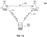
- Figures 6-12 show various operation scenarios for a WTRU that may communicate with two different sites (eNBs). Details presented below that are associated with Figure 6 may apply to all other scenarios unless alternate details are explicitly mentioned in each of the respective scenarios.
- FIG. 6 shows a wireless communication system 600 including a WTRU 605 and two Sites (eNBs) S1 and S2.
- the WTRU 605 may be connected with site S1 via a DL 610 (dlCCC1 on dlF1), and via a UL 615 (ulCC1 on ulF1).
- the same WTRU 605 may be connected with Site S2 via a DL 620 (dlCCC2 on dlF2), and via a UL 625 (ulCC2 on ulF2).
- An X2 interface 630 may allow Sites S1 and S2 to communicate with each other.
- the DL 610 may carry the pCell, and the UL 615 may be the primary UL CC where UCI may be transmitted via a PUCCH separately.
- the DL 620 may be configured as the sCell and the UL 625 may only carry PUSCH where UCI is piggybacked in a PUSCH.
- the UCI when simultaneous PUCCH and PUSCH are not configured, the UCI, (e.g., ACK/NACK and channel state information (CSI)), may be transmitted in a single UL carrier selected according to the following rules.
- the WTRU 605 When the WTRU 605 has a PUSCH transmission on the primary cell, the UCI may be transmitted over the primary cell.
- the WTRU 605 When the WTRU 605 has a PUSCH transmission on one or more secondary cells, but not on the primary cell, the UCI may be transmitted over one secondary cell.
- UCI for the DL 620 may be sent over the X2 interface 630.
- the decision of whether to send UCI either piggybacked on an sCell PUSCH, or to send it over the X2 interface 630, may depend on the implementation and may be influenced by several factors, such as delay over the X2 interface 630, whether cross-carrier scheduling may be performed in a pCell for an sCell to take advantage of better inter-cell interference management, and the like.
- the UL 615 may be the anchor carrier for Site S1 and the UL 625 may be the anchor carrier for Site S2.
- the UCI intended for Sites S1 and S2 may be sent on its respective anchor carrier.
- PL referenceSignalPower - higher layer filtered RSRP.
- a path loss estimate for each UL CC may be used.
- the path loss PL 0 on one of the DL CCs for example, a CC that was defined as the anchor may be estimated.
- the offset value may be used to offset the path loss difference due to the frequency separation between different UL CCs.
- a linear combination of the path losses estimated on several or all of the DL CCs may be used as PL 0 .
- the UL power control mechanism may depend on the power amplifier (PA) configuration of the WTRU 605, the number of UL CCs, and whether there is a single PA used for all UL CCs, or possibly one PA for each CC, or one PA for several CCs, the association of the DL CCs and/or the transmitting sites to the UL CCs and determination of the open loop component of the UL power control, the signaling from the network to manage the closed loop component of the UL power control, and the differences of power control mechanisms for data and control transmission.
- PA power amplifier
- the association of the UL CCs to the sites may be such that all UL CCs may or may not be associated with one site.
- a UL CC may be associated to a "virtual" site.
- transmission on different DL CCs may be generated on physically separated sites.
- the path losses from these sites (S1, S2) to the WTRU 605 may be significantly different. Therefore, a separate path loss may be estimated for each of the transmission sites.
- the path loss for a given transmission site may be estimated by using one of the DL CCs used by that site for transmission, for example, one that may have been defined as the anchor carrier for that transmission site.
- a linear combination of the path losses estimated on some or all of the DL CCs may be used by that site.
- the path loss estimate used in the UL power control for a specific UL CC may depend on the configuration of UL CCs.
- the association of the UL CCs to different transmission sites may be used to coordinate UL interference and/or for load balancing purposes.
- separate PDCCHs may be transmitted from transmission sites.
- a separate PDCCH per DL CC may be sent to schedule transmission resources on that carrier.
- a PDCCH transmitted on one DL CC may schedule resources on another DL CC with the use of a carrier indication field.
- an UL grant that allocates the resources for transmission on a specific UL CC may be transmitted by the transmission site which the UL CC is associated with. There may be an association with the UL CC to one of the DL CCs used for transmission by that site. This DL CC may be used to transmit the UL grant.
- the transmit power control (TPC) command may also be carried in the same component carrier as the UL grant.
- the ACK/NACK due to the UL transmission may be also carried on this DL CC.
- the UL grant for a UL CC may be transmitted by a different site than the site which the UL CC is associated with.
- the UL grant may include a UL CC, (and transmission site), indication field to indicate to the WTRU 605 which UL carrier the resource allocation information may be for.
- the TPC command may also be carried similarly.
- the transmission sites may need to exchange information, such as CSI parameters, (including CQI/precoding matrix indicator (PMI)/rank indicator (RI) and the like), power control parameters (e.g., TPC) and the like, so that scheduling decisions may be implemented.
- UL control data may include an ACK/NACK due to the DL transmission, channel state information (CSI) including CQI/PMI/RI, channel quantization information, and the like, which may be used for scheduling decisions, scheduling requests, and the like.
- CSI channel state information
- UL control data may be carried in a UL control channel (PUCCH) or PUSCH.
- the PUCCH may be mapped to one UL CC.
- This UL CC may be selected such that the path loss to the receiving site is the smallest among all possible sites/carriers.
- the PUCCH power control may be adjusted by using the parameters for this site, (e.g., the path loss, and the like).
- PUCCH information may be mapped to several UL CCs where each UL CC may be associated with a different transmission site.
- the PUCCH in one UL CC carries the control data for the corresponding transmission site. PUCCH power on a specific UL CC is adjusted such that PUCCH is reliably received at the corresponding transmission site.
- UL power control associated with CA may be implemented using various parameters that are specific to the DLs 610 and 620, each having a defined maximum power.
- the total UL power may be also restricted by a maximum power related to the WTRU class.
- the pathloss used by UL power control may be derived based on the configuration from the network in terms of which of the DLs 610 and 620 to measure, whether to apply offset per DL, and the like.
- TPC in a UL grant may be applied to a UL CC for which the grant applies, (i.e., a TPC sent in a UL grant from the DL 610 may be applied to the UL 615 in site S1.
- the TPC field in the UL grants configured with CIF may control the power of the PUSCH and SRS transmissions in the UL CC that may not be linked with the DL CC in which the grant is transmitted.
- the DL 610 may send TPC to regulate UL power of the UL 625 if necessary.
- any such joint-scheduling effort may require data exchange over the X2 interface 630.
- the benefit may be reducing overhead from signaling on the DL 620 as much as possible, and in utilizing the DL 620 for data use.
- the cross-carrier UL power control may become necessary.
- TPC in DL grant may be applied to a UL CC for which the ACK/NACK may be transmitted, (i.e., a TPC command sent in a DL grant from the DL 610 may be applied to the UL 615 in Site S1).
- TPC in DCI format 3/3A may be applied to the UL CC using a combination of a TPC index in RRC signaling and TPC-PUSCH-radio network temporary identifier (RNTI).
- RNTI radio network temporary identifier
- a power headroom report (PHR) may include CC-specific reports for PUCCH/ PUSCH. Since Type 2 PHR may only be valid for pCell, in this scenario, presuming the UL 615 is the primary cell (pCell) UL and the UL 625 is the secondary cell (sCell) UL, Type 1 PHR may be used for the UL 615 and Type 2 PHR may be used for the UL 625. Therefore, there may be instances that the WTRU 605 simultaneously transmits Type 1 and Type 2 PHRs.
- Maximum power scaling may be conducted per channel with priority on PUCCH power followed by PUSCH including UCI and then PUSCH.
- a new priority may be introduced that is related to the site configuration. For example, instead of applying the priority based on the channel, the UL connected to one site may be scaled down, regardless of what channels are carried. This may be a simple radio frequency (RF) attenuation on one frequency in this scenario, instead of going through the scaling calculation in baseband.
- RF radio frequency
- Figure 7 shows a wireless communication system 700 including a WTRU 705 and two Sites (eNBs) S1 and S2.
- the WTRU 705 may be connected with Site S1 via a DL 710 (dlCCC1 on dlF1), and via a UL 715 (ulCC1 on ulF1).
- the same WTRU 705 may be connected with Site S2 via a DL 720 (dlCCC2 on dlF1), and via a UL 725 (ulCC2 on ulF2).
- An X2 interface 730 may allow sites S1 and S2 to communicate with each other.
- a fuzzy cell configuration may implement a common scheduler that performs scheduling of resource of carriers belonging to different sites based on CSI reported with respect to each site and exchanged via the X2 interface 730 and consolidated at the common scheduler.
- the DLs 710 and 720 are both at the same frequency, if both carry a PDCCH, despite the orthogonality afforded by a physical cell identifier (PCI) scrambled at bit level, the performance blind decoding of the PDCCH on the DL 710 and 720 may be degraded.
- PCI physical cell identifier
- the common scheduler may insure that the RBs used for data transmission on the DL 710 may not be scheduled on the DL 720 to avoid interference.
- the DLs 610 and 620 may operate on two different frequencies in the system 600 of Figure 6 . Except for this restriction, the scenario of Figure 7 may be similar to the scenario of Figure 6 in terms of its UL aspects.
- FIG. 8 shows a wireless communication system 800 including a WTRU 805 and two Sites (eNBs) S1 and S2.
- the WTRU 805 may be connected with Site S1 via a DL 810 (dlCCC1 on dlF1), and via a UL 815 (ulCC1 on ulF1).
- the same WTRU 805 may be connected with Site S2 via a DL 820 (dlCCC2 on dlF2), and has no associated UL CC.
- An X2 interface 825 may allow Sites S1 and S2 to communicate with each other.
- All feedback and HARQ information corresponding to DL 820 may be multiplexed onto the UL 815, transmitted to Site S1 and subsequently forwarded to Site S2 via the X2 interface 820.
- Power control and timing advance may be regulated by Site S1 via the DL 810.
- the latency introduced by X2 interface information forwarding may not affect the HARQ/CSI time line, because the common scheduler is aware of in which sub-frame Site S2 may transmit a certain transport block (TB) in the DL 820, and instruct Site S1 to expect the associated ACK/NACK in the sub-frame that is four sub-frames later.
- the HARQ transmission on the DL 820 may initiate at Site S2 and terminate at Site S1.
- Site S1 may inform Site S2 regarding the retransmission in sufficient time so that the WTRU 805 receives the retransmission exactly eight sub-frames later.
- the multiplexing of ACK/NACK associated with both the DLs 810 and 820 onto the UL 815 may require additional signaling from Sites S1 to S2 in order for proper operation of the DL 820 over the X2 interface 825.
- the WTRU 805 may receive UL grants for the UL 815 from the DL 810.
- the common scheduler (likely residing at site S1 in Figure 8 ), may readily have CSI associated with both Sites S1 and S2, and may perform a common pool scheduling and apply cross-carrier scheduling in PDCCH using CIF for DL resource scheduling.
- Figure 9 shows a wireless communication system 900 including a WTRU 905 and two Sites (eNBs) S1 and S2.
- the WTRU 905 may be connected with Site S1 via a DL 910 (dlCCC1 on dlF1), and via a UL 915 (ulCC1 on ulF1).
- the same WTRU 905 may be connected with Site S2 via a DL 920 (dlCCC2 on dlF1), and may have no associated UL CC.
- An X2 interface 925 may allow Sites S1 and S2 to communicate with each other. This scenario may be similar to the system 800 of Figure 8 in terms of UL configuration, and may be similar to the system 700 of Figure 7 in terms of DL configuration.
- FIG. 10 shows a wireless communication system 1000 including a WTRU 1005 and two Sites (eNBs) S1 and S2.
- the WTRU 1005 may be connected with Site S1 via a DL 1010 (dlCCC1 on dlF1), and via a UL 1015 (ulCC1 on ulF1).
- the same WTRU 1005 may be connected with Site S2 via a DL 1020 (dlCCC2 on dlF2), and the UL 1015.
- An X2 interface 1025 may allow Sites S1 and S2 to communicate with each other.
- All feedback and HARQ information corresponding to the DL 1020 may be multiplexed onto the UL 1015.
- Site S2 may demodulate and decode the UL 1015 accordingly.
- the Site S2 may have the ability to aperiodically trigger a sounding reference signal (SRS) for UL channel estimation as Site S1 does, and also may have the ability to schedule CSI information separately from Site S1.
- SRS sounding reference signal
- the common scheduler may need to coordinate the UL resource allocation between Sites S1 and S2.
- two sets of power control and timing advance mechanisms may be employed at two sites intended for one WTRU, and either selectively or collectively this information may be evaluated and reconciled. For example, during the period where the Site S1 is subjected to a satisfactory UL SINR from the WTRU 1005, more RBs on the UL 1015 may be scheduled for the Site S1. This may selectively transmit to the Sites S1 or S2 in a different period mat equate to a type of time division multiplexing (TDM) applied to the UL 1015.
- TDM time division multiplexing
- the common scheduler may look for a type of balance between UL SINR at the Site S1 and the SINR at the Site S2, and may generate one common set of TPC bits accordingly.
- the sub-frame of the UL 1015 may arrive at the Sites S1 and S2 at different time instances and, in turn, may lead to two different timing advance values TA1 and TA2. Depending on the difference between TA1 from S1 and TA2 from S2, the selective and collective approaches may be applied.
- the usage of the UL 1015 may be optimized to reach Sites S1 and S2 simultaneously or alternatively.
- Figure 11 shows a wireless communication system 1100 including a WTRU 1105 and two Sites (eNBs) S1 and S2.
- the WTRU 1105 may be connected with Site S1 via a DL 1010 (dlCCC1 on dlF1), and via a UL 1115 (ulCC1 on ulF1).
- the same WTRU 1105 may be connected with Site S2 via a DL 1120 (dlCCC2 on dlF1), and the UL 1115.
- An X2 interface 1125 may allow Sites S1 and S2 to communicate with each other.
- This scenario may be similar to the system 1000 of Figure 10 in terms of UL configuration, and similar to the system 700 of Figure 7 in terms of DL configuration.
- Figure 12 shows a wireless communication system 1200 including a WTRU 1205 and two sites (eNBs) S1 and S2.
- the WTRU 1205 may be connected with Site S1 via a DL 1210 (dlCCC1 on dlF1) and may have no associated UL.
- the same WTRU 1205 may be connected with Site S2 via a UL 1215 (ulCC2 on ulF1), and may have no associated DL.
- An X2 interface 1220 may allow Sites S1 and S2 to communicate with each other.
- All information related to feedback, CSI, power control and timing advance may be exchanged between the Sites S1 and S2 via the X2 interface 1220.
- UL power control may only be used to estimate the path loss between the Site S1 and the WTRU 1205, while the TPC bits may be generated based on the UL SINR experienced at the Site S2.
- the impact of this mismatch may be mitigated by applying an offset to the path loss estimated at site S1 to approximate that the path loss is at the Site S2.
- the orthogonality of OFDM-based UL transmission may be maintained when signals from different WTRUs of the same sub-frame arrive roughly in an aligned fashion at the eNB in one cell. A misalignment exceeding the cyclic fix may cause interference.
- the timing advance may be considered a mechanism applied to a pair of associated DL and UL carriers.
- a dedicated timing advance may be applied on each CC, or a common timing advance may be sufficient for all CCs.
- Fuzzy cell scenarios imply further that the pair of associated DL and UL carriers used by one WTRU may be connected to two different sites. Also, one WTRU may have two UL carriers connected to two different sites. Therefore, a WTRU may need to administrate a set of timing advances, each specific to both CC and site, (two-dimensional index).
- One basic rule may be that a WTRU maintains separate TAs for each CC and site.
- TA tracking area
- the breaking of the paring of DL and UL carriers by a fuzzy cell between two different sites may cause various issues.
- the first issue may be that the timing advance may be determined by the eNB of one site based on the received timing measurement of UL data/control/reference signals in that particular cell. All WTRUs in a particular cell may time the transmission of the UL with a reference of the frame timing of the DL carrier in the particular cell. If a WTRU uses DL frame timing on one carrier from one site, yet applying a timing advance command received from another site, the WTRU DL and UL frame timing may not align in terms of HARQ timing.
- a WTRU may use CCC1-DL for DL data (PDSCH) and DL, (i.e., the associated UL CC1-UL is not active), from Site S1, and CCC2-DL for DL control (PDCCH) and the associated UL, CC2-UL, from Site S2.
- the reference DL frame timing of CC1-DL may be t1 and the reference DL frame timing of CC2-DL may be t2. Since the data originates from CC1-DL, the HARQ timing of this specific WTRU may be timed against t1. Meanwhile, all other WTRUs in Site 2 may time the UL transmission relative to the DL frame timing t2, and Site 2 may use all of these UL transmissions to generate a common timing advance.
- the timing advance command may indicate the change of the UL timing relative to the current UL timing as multiples of 16 ⁇ T s . If the difference between t1 and t2 is large, timing advance change may break the maximum of 0.67 ms limit, and as a result, the processing of UL ACK/NACK at this WTRU may not be completed when the associated UL transmission is due. If the WTRU has a safeguard against this anomaly and pulls the UL timing within the limit, Site S2 may find the WTRU UL misaligned with other WTRUs.
- the separation of an associated pair of DL and UL carrier to different sites may be involved with the HARQ timing, even without a timing advance impact. If both sites are synchronized, (i.e., t1 and t2 are close to each other), this issue may be alleviated.
- the UL ACK/NACK may be forwarded from Site S2 via the X2 interface to Site S1, the resulting delay may be considered. Since an X2 interface may be realized as a TCP/IP network, the delay may be so large that it cannot be compensated for.
- One solution may be to deploy an RF amplify-and-forward link between sites to forward a UL ACK/NACK timely.
- the ACK/NACK may be forwarded directly from Site S2 to Site S1 for processing via a radio link that may be in a different frequency band. Such a radio link may facilitate other timing-sensitive signal transfer between sites in fuzzy cell scenarios as well.
- An alternative approach for the scenario above is for Site S1 to directly listen to CC2-UL at the same time as site S2 directly listens to CC2-UL.
- the corresponding solution for a TA may be an ACK/NACK multiplexing in one UL CC corresponding to multiple DL CCs from different sites. Since each DL CC may have a UL ACK/NACK transmitted back to the same site, HARQ timing may not be an issue. Given that timing advance is on a per site basis in this case, it may be difficult to reconcile both timing advances on one UL carrier unless both CCs from these two sites are synchronized.
- a timing advance commands from two sites may be evaluated and applied according to the smallest TA amongst all TAs received from multiple sites intended for one UL CC may be applied on this UL CC. No excessive advancement in the UL timing may occur concerning the DL CC from the site where other TAs originate from.
- a timing misalignment may be caused by the timing difference between two sites, but given that the two sites are synchronized, this misalignment may not be significant.
- the base stations are divided into multiple clusters of the same shape with each of which consists of N cells. For example, if there are F CCs available, a power profile may be found for these F CCs in a cluster, and the same power profile may be reused for all of the other clusters. For one cluster, there may be a set of K test locations which may bee uniformly distributed.
- a WTRU may be connected to the BS with the maximum C/I, which may be denoted by SIR(k, f).
- SIR(k, f) the maximum C/I
- p_eq is the transmission power from each base station for each CC, assuming a uniform power profile over space and frequency.
- This constraint may be for fair comparison purposes based on the performance of a non-fuzzy cell scenario, (i.e., the uniform power allocation case).
- P_lb lower bound
- P_ub an upper bound by assuming that each CC has its own power amplifier at the BS.
- a different set of power constraints may be considered.
- a WTRU may require more than one CC, with CC1 connecting to Site A and CC2 connecting to Site B as specified in the previous fuzzy cell solution.
- AWGN rate additive white Gaussian noise
- C/I may be calculated for each location, and CCs, from which the sum rate R(k) may be obtained and then the corresponding transmit power (TP) CDF is obtained.
- a power profile that may improve a user's cell-edge performance may cause performance degradation for non cell-edge users.
- other constraints may be added as well to ensure that the non-cell-edge user's performance loss may be within a certain range.
- R50, R80 and R90 may be denoted as being the 50%-tile, 80%-tile and 90%-tile TP values, respectively.
- Equation (5) the bandwidth is fixed for each CC, and the system load is irrelevant, (i.e, the number of users that connect to the same BS using the same CC), which may not reflect the entire scenario, since with non-uniform power allocation, the BSs with different powers on a particular CC may have a different coverage area, and thus, the particular CC may have a different number of users. As a consequence, the bandwidth available for each user may also change when compared to the equal power case.
- the rate constraints may also be changed accordingly.
- MATLAB's genetic algorithm (GA) toolbox may be relied on to determine the local optimum.
- Some numerical results may be provided with the assumption that there are three sectors, (with 120 degree directed antennas), per site, and each cluster contains one site (3 cells).
- Three CCs may be available at each cell, and since there may be three cells in a cluster, there may be a total of nine (9) power parameters (three per CC) that may be adjusted.
- another constraint may be imposed on the nine parameters with the assumption that the power profile of the CCs are being reused by shifting.
- the optimized power profile may be [50.768, 16, 16] in dBm with a worst location's best C/I being 4.673 dB, compared to the equal power case's 1.56 dB. More than 3 dB's gain may be obtained by employing non-uniform power distribution.
- Solving Equations (6) and (7) with the assumption of V 3, (i.e., a WTRU may use all the three CCs), basically provides the same set of power profiles, and the BS may attempt to mimic a frequency reuse factor of three case.
- Figure 14 shows an optimized carrier-to-interference ratio (C/I) map for CC1 with a power profile [50.76, 16, 16] in dBm. As shown in Figure 14 , each different CC may try to cover a different area by boosting power in one sector and minimizing power in the other two sectors.
- C/I carrier-to-interference ratio
- Figure 15 shows that the cell-edge user performance may be significantly improved with un-equal power allocation when compared to the equal power case.
- Figure 16 is a graphical representation of a CDF of a normalized sum rate assuming each WTRU uses 3 CCs.
- the "reuse 3" curve may denote the normalized TP CDF with the power profile optimized with Equation (7), where a non-normalized TP may be used in calculating cost.
- Equation (9) the power profile [38, 47, 48] dBm may be obtained, whose CDF is also depicted in Figure 16.
- Figure 16 shows that by considering normalized sum rate, the solution of Equation (9) may provide approximately 15% cell-edge user performance improvement when compared to the equal power case. At the same time, the non-cell-edge user's performance loss may be kept under control.
- Equation (9) may be used to handle any type of scheduler, instead of the simple equal bandwidth sharing, as long as the CDF may be obtained with a given power profile. Also, the above framework may also be extended to the case by also allowing an antenna pattern to change.
- the cellular system may be inherently susceptible to error due to the nature of an underlying unsecured physical medium over the air.
- the support for user mobility in the cellular system may further increase the number of possible error scenarios.
- error handling may be performed in a CC cooperation network.
- a concept for enabling retention of working data flow for CA using a multi-site (eNB) when there is a communication error with a primary communication site (eNB) is described herein.
- eNB multi-site
- eNB primary communication site
- Various CC cooperation network-related RAN procedures that handle individual CC failure while a CC cooperation network including multiple sites is in use will also be described.
- a RLF is a procedure to restore a WTRU from an unrecoverable physical communication error condition to regain system access.
- Radio link quality may be measured as a hypothetical PDCCH error rate, considering PCFICH errors with an assumed transmission configuration.
- the WTRU may monitor a subcarrier reference signal for DL radio quality against quality thresholds Qin and Qout every frame or during a DRX active time, if a DRX configuration is applied.
- the physical layer may then provide in-sync and out-sync indications to the RRC entity when the quality thresholds are exceeded.
- RLF may be declared by a WTRU RRC upon reception of consecutive out-of sync indications, and may not receive consecutive in-sync indications for a subsequent duration.
- the WTRU may suspend current data traffic flow and then perform cell reselection. Upon a successful cell reselection, the WTRU may initiate an RRC connection reestablishment procedure to resume the data traffic transfer if access stratum (AS) security is activated. If the AS security is not activated, the WTRU may perform RRC connection release, (release all resources associated with established RB), and then the WTRU may enter an RRC_IDLE mode.
- AS access stratum
- a WTRU may be configured to receive on multiple CCs.
- CA may support deployments where the cells on the different CCs may have different coverage areas, while still originating from the same eNB. Therefore, PDCCH reception on a subset of the DL component configured for PDCCH reception may fail, while other CCs may still have an operational PDCCH reception. This may expand the possible failure scenarios to one or more CCs, and all CCs failing.
- An RLF procedure may be declared only for the scenario where all CCs fail.
- the eNB may consider explicit signaling or implicit eNB detection to remove failed CC links without using an RRC connection reestablishment procedure.
- only traffic channel associated with the affected carrier may be reset/redirected while the other carriers may continue to operate "as is”.
- the serving eNB may assign a UL radio resource to a WTRU with an active connection via a PDCCH in the form of either a semi-persistent-schedule (SPS), (i.e., an RRC connection message configuration), or the WTRU may have to request the eNB for a UL resource via a PUCCH channel.
- SPS semi-persistent-schedule
- Implicit RLF on the WTRU side may apply to the detection of a loss of a UL communication by a layer 2 (L2)/layer 3(L3) protocol.
- L2 layer 2
- L3 layer 3
- the MAC may revert to initiate a RACH procedure and, if a RACH procedure also fails, then the RRC may be informed to initiate an RRC connection reestablishment procedure, (RLF reporting).
- the WTRU may monitor HARQ ACK/NACK provided by the eNB on a PDCCH after receiving the transmission. If the eNB stops receiving UL data on an assigned SPS channel for up to eight (8) transmissions, the eNB may interpret the situation as an implicit WTRU release, and reconfigure (release) the resource. If a DL PDCCH is lost as well in this situation, no further RRC configuration, UL grant or UL ACK/NACK may be possible, which may lead to an HARQ failure, causing a UL radio link control (RLC) transmission failure, (since the release of a failed SPS-configured channel may not have been received by the WTRU for deactivation). Once the maximum number of RLC retransmissions has been reached, the WTRU RRC may be informed to initiate an RRC connection reestablishment procedure (RLF reporting).
- RLC radio link control
- the WTRU MAC and RLC mechanisms may be based on RACH transmission failures.
- the WTRU may be granted a maximum number of random access (RA) retries (preambleTransMax) from SIB2 of the active CC, or in the case of handover, may be included in the mobility control information IE of an RRCConnectionReconfiguration message.
- RA random access
- the RRC may be informed by the MAC when the maximum RA retries has been reached, or the MAC may signal the RRC when the maximum RA retries has been reached due to the introduction of CA, (i.e., signal when a CC is attempted or all available CCs are attempted).
- the RLC mechanism may only be applicable to an acknowledge mode (AM) channel based on an RLC transmission failure.
- the WTRU may be provided with a maximum number of retries (maxRetxThreshold) as part of a radio resource configuration in the RRC connection setup/reconfiguration/reestablishment message.
- the WTRU RRC may be informed by the RLC when a signaling radio bearer (SRB) or a data radio bearer (DRB) may has exceeded a maximum transmission threshold.
- SRB signaling radio bearer
- DRB data radio bearer
- the RLF procedure may cause the temporarily suspension of the data traffic, or in a worse case scenario, dropping a call. This behavior is not desirable for a WTRU using CA, for which normal data traffic on another CC may be unaffected by the RLF on a serving CC.
- Figure 17 shows an example radio link failure due to mobility in a CC cooperation network. It is desirable for a WTRU to signal an RLF condition to a network having two eNBs (eNB 1 and eNB 2) using a CC on different sites. As shown in Figure 17 , the WTRU may initially be configured to receive a high data throughput (1705) using CA from 2 CCs (CC A and CC B), both from eNB 1. A dedicated control channel (DCCH) may be established on CC A, which is a special cell. As the WTRU moves away from eNB 1 towards eNB 2, the WTRU may leave the eNB 1 coverage of CC B (1710).
- DCCH dedicated control channel
- a partial handover may reconnect the WTRU receive path on CC B to eNB 2 to regain the desired data throughput.
- the DCCH may remain on CC A.
- the WTRU may then move behind a skyscraper that creates shadowing leading to an RLF on the CC A link (1715). While the WTRU may continue to receive a satisfactory data stream on CC B from eNB 2, both the DCCH and the data path on CC A may be lost.
- the RLF procedure may trigger a re-establishment of an RRC connection, thus interrupting data transfer on both CCs.
- the reporting of partial RLF detected by the WTRU may be caused by a loss of synchronization to the eNB 1, or by some other means that stops communication with eNB 1, may still be sent to the eNB 2 on CC B.
- the partial RLF reporting without a special cell may use a different eNB processing procedure, depending on the RRC connection configuration at the time of detection.
- CC B may be the "special cell" and CC A may be part of the CC cooperation network.
- an RRC connection handover (during step 1710 or before the WTRU enters a shadowing position in step 1715), may cause an EPS bearer to be forwarded to the eNB 2.
- the WTRU context and signaling may be handled in the eNB 2. Therefore, the signaling of a partial RLF (CC B failure) notification to a special cell (on eNB 2), as well as recovery processing, (e.g., CC B release or reroute), may be performed.
- CC A may be the "special cell" and CC B may be part of the CC cooperation network.
- CC B may be reconfigured onto eNB 2 during step 1710.
- the responsibility to make decisions/commands to control the WTRU's behavior may remain with eNB 1.
- the signaling of a partial RLF notification when received on eNB 2 may need to be forwarded to the eNB 1 for further WTRU configuration. If this reporting is not delivered to the eNB 1, or forwarded after the eNB1 implicitly detects RLF, the eNB 1 may drop the active call if communication via CC A may not be restored.
- a WTRU notification of RLF on individual active CC(s) in the CC cooperation network to the serving eNB is described.
- the WTRU may explicitly signal a partial RLF to an eNB in a multiple-site CA configuration.
- the WTRU may use a PDCCH or PUSCH associated with the serving eNB to explicitly signal a partial RLF condition to the serving eNB.
- the WTRU may explicitly signal a partial RLF condition on another available CC.
- the reporting of a partial RLF to the eNB 1 may be beneficial in comparison to an implicit eNB 1 RLF detection, since this may enable the mechanism that may allow eNB 1 to initiate a seamless handover and use X2 data tunneling to minimize data packet losses during the transition.
- the direct notification of a partial RLF may be signaled over an X2 interface by a cooperating eNB to a serving eNB.
- a cooperating eNB may not able to communicate over an X2 interface
- communication over an S1-mobility management entity (MME) interface may be implemented.
- FIG. 18 shows an eNB access stratum (AS) protocol architecture 1800 including two WTRUs 1805 and 1810, and three eNBs 1815, 1820 and 1825.
- Each of the eNBs 1815, 1820 and 1825 may include an RRC 1830, an L2 entity 1835, a physical (PHY) layer entity 1840 and a radio resource management (RRM) unit 1845 for CC centric resource management.
- RRC radio resource management
- This architecture may maintain a one-to-one peer RRC entity relationship, and may ensure that there is only one terminating point for RRC signaling.
- the RRM units 1845 may communicate with each other via inter-node X2 application protocol (X2AP) interfaces 1850.
- X2AP inter-node X2 application protocol
- An X2 interface user plane protocol based on GPRS tunneling protocol 1855 may be used for in-band data traffic signaling between the L2 entities 1835 in eNBs 1815 and 1825.
- the RRM unit 1845 may be the functional entity on the eNB that may be responsible for managing the access stratum (AS) radio resources. There may be one master RRM 1845 on each of the eNBs 1815, 1820 and 1825 that may be responsible for allocation of eNB specific backhaul or air interface resources. The individual CC(s) on the eNBs 1815, 1820 and 1825 may be managed as part of a master RRM unit, (that may be taking input from sub-modules that monitor dedicated CCs).
- the RRC 1830 may be the functional entity responsible for tracking, (request and return), resources assigned to a dedicated WTRU, as well as processing signaling protocols responsible for signaling AS assignment to a single WTRU.
- the RRC 1830 may negotiate with the RRM unit 1845 to obtain required resources to provide user service(s) at requested quality of service (QoS).
- QoS quality of service
- the inter-eNB X2AP interfaces 1850 may be the signaling interfaces for the eNBs 1815, 1820 and 1825 in a cooperative active set.
- the eNB access stratum (AS) protocol architecture 1800 of Figure 18 may include two WTRUs 1805 and 1810 with an active connection to receive connection service from three eNBs 1815, 1820 and 1825.
- the WTRU 1805 may communicate with only eNB 1820.
- the WTRU 1810 may communicate with the eNB 1815 (the serving eNB) and the eNB 1825 (the cooperating eNB) using an RRC connection, where a RRC connection may be established or reconfigured at the eNB 1815 to include a CCC for data-splitting.
- the eNB 1815 may exchange system information configuration and radio environment information with the neighbor eNBs 1820 and 1825, which together may form the candidate "cooperative active set" for the WTRU (1805, 1810).
- the eNB 1815 may maintain the RRC context for the WTRU 1810 to facilitate mobility management and data routing.
- the eNB 1825 may maintain a partial RRC context to facilitate data-forwarding and control signaling for this WTRU 1810.
- the WTRU 1810 may perform measurements on the eNB 1820 as a candidate to join cooperative transmission.
- the eNB 1820 may not maintain the WTRU 1810 RRC until cooperative transmission from the eNB 1820 may be activated by the serving eNB 1815.
- a partial RLF report may be sent to a CC of a cooperating eNB 1825 by the WTRU 1810.
- the following embodiments are alternative WTRU reporting mechanisms, which may be categorized and described below in terms of "RRC based” or “non-RRC based” reporting.
- a UL path associated with an SRB may exist on the cooperating eNB. This may or may not be the case with the cooperating eNB 1825.
- a WTRU using a cooperating CC, for DL data transfer only may not be required to setup a UL transport channel.
- the types of RLF detections that may be reported based on this method are WTRU explicit/implicit RLF detections.
- non-RRC-based partial RLF reporting if a non-RRC-based signaling method is employed, modification to an existing X2 interface may be required for the cooperating eNB 1825 to provide this indication to the serving eNB 1815.
- the types of RLF detections that may be reported based on this method are based on WTRU implicit UL RLF detection by a MAC using a MAC control element (CE), or modifying a physical control channel header, (such as a PUCCH header), for information insertion as well as eNB RLF detections.
- CE MAC control element
- the cooperating eNB 1825 may forward a partial RLF report to the serving eNB 1815 for resource reassignment.
- One alternative eNB forwarding solution corresponding to various possible WTRU reporting mechanisms may include the use of an on-demand inter-eNB signaling configuration by establishing an X2 interface, or a common control channel (CCCH) or a dedicated control channel (DCCH), after reception of an RLF indication by the cooperating eNB 1825. Since only a CC with active data path is used to signal an RLF, the cooperating eNB 1825 may be aware of the WTRU context, and therefore may identify the location of the serving eNB 1815 to be forwarded to. A new X2 message may be created to forward an RLF signal as an encapsulated data or explicit indication. Alternatively, an X2 data plane interface may be modified to allow a special configuration in the tunneling protocol frame header to indicate that a CCCH/DCCH message for the WTRU 1810 is sent.
- CCCH common control channel
- DCCH dedicated control channel
- Another alternative eNB forwarding solution corresponding to various possible WTRU reporting mechanisms may include using a preconfigured CCCH/DCCH path to all cooperating eNBs and configure a transport channel associated with a DRB as well as an SRB on the cooperating eNB 1825.
- Inter-eNB communication may generally described in terms of the following two types: an X2AP message defined that may be used for communicating eNB/BS system relevant information, and an X2 data transport that may be used for in-band data traffic signaling.
- an X2AP message defined that may be used for communicating eNB/BS system relevant information
- an X2 data transport that may be used for in-band data traffic signaling.
- Configuring a CCCH/DCCH logical channel over an X2 interface on demand may be possible. However, this may require an X2AP exchange between two relevant eNBs to establish a new tunneling path. This may incur a delay which may render less desirable the establishment of a dynamic logical channel.
- explicit signaling over an X2 interface may be performed, since the coordinating eNB 1825 may be aware of the WTRU context, (setup on data-split), and the associated serving eNB 1815.
- Two possible approaches may include the creation of a new X2AP message to provide specific WTRU information.
- this new WTRU-specific X2AP message may be used to forward the RRC message, (received on a DCCH or a CCCH), to the serving eNB 1815 for delivery to its RRC 1830 for further processing.
- the X2 tunneling protocol data header may be modified to provide explicit in-band signaling over an X2 interface, since the cooperating eNB 1825 is already processing WTRU-specific data traffic on the X2 tunnel. There is some overhead expected on the X2 tunnel, since multiple DRBs are bundled on this tunnel. Therefore, the X2 tunnel overhead may be modified by adding a parameter bit field to distinguish if the pay load is DRB or SRB, (it not necessary to distinguish between SRB 0, 1, or 2 as the RRC 1830 may be able to decode this information as part of abstract syntax notation one (ASN.1) decoding).
- ASN.1 decoding abstract syntax notation one
- the X2 tunnel overhead may be modified by adding a bit field to identify the forwarding destination channel ID (depending on the data-split mode: packet data convergence protocol (PDCP)-split (RB ID), RLC-split (logical channel ID), and MAC-split (transport channel ID).
- PDCP packet data convergence protocol
- RB ID packet data convergence protocol
- RLC-split logical channel ID
- MAC-split transport channel ID
- notification of a RLF failure may be performed by adding a new MAC control element.
- the MAC CE reporting along with other implicit DL RLF detection performed on the eNB may be detected by the cooperating eNB 1825, depending on the method used to split the data.
- RLC packet data convergence protocol
- RLC level split When a packet data convergence protocol (PDCP)/RLC level split is performed, implicit detection (RLC or PHY sync failure) as well as MAC CE reporting may be terminated on the cooperating eNB 1825. However, the RLF indication may be forwarded to the RRC 1830 on the serving eNB 1815.
- PDCP packet data convergence protocol
- RLC level split When a packet data convergence protocol (PDCP)/RLC level split is performed, implicit detection (RLC or PHY sync failure) as well as MAC CE reporting may be terminated on the cooperating eNB 1825. However, the RLF indication may be forwarded to the RRC 1830 on the serving eNB 1815.
- a new X2AP message may be created for providing specific WTRU status.
- the information provided in the new X2AP message may include the radio link that failed and how the decision may have been obtained, (i.e., implicit detection (DL RLC unrecoverable error, or PHY sync failure), or MAC CE indication of partial RLF reporting from the WTRU).
- a special frame format may be added to the X2 tunneling protocol to provide the information provided in the new X2AP message.
- a MAC level split may be performed, whereby an implicit detection (PHY sync failure) and MAC CE reporting may be terminated on the cooperating eNB 1825.
- PHY sync failure PHY sync failure
- MAC CE reporting may be terminated on the cooperating eNB 1825.
- a solution similar to the PDCP/RLC level split may apply, except that the implicit RLC detection may occur on the serving eNB 1815, and therefore may not be needed in the possible data field.
- an additional configuration for an SRB from the serving eNB 1815 to the cooperating eNB 1825 during RRC connection reconfiguration may be implemented, (when a data-split path is configured).
- An active RRC connection may be security activated, and all RRC messages may be integrity protected and ciphered by a PDCP. Therefore, regardless of the proposed data-split model, (PDCP, RLC, or MAC), a logical control (CCCH/DCCH) channel establishment over an X2 interface that may be bundled with the data traffic may be sufficient to provide the necessary routing path for the cooperating eNB 1825 to forward the RRC message, (explicit partial RLF indication), to the serving eNB 1815.
- One assumption for reporting an RLF to the serving eNB 1815 over the X2 interface 1850 may be that this mechanism may trigger the serving eNB 1815 to initiate an RLF recovery before an implicit detection of the RLF leads to a dropped call, given that the RLF over the CC A interface may signify that communication with eNB 1 may be completely lost. Therefore, the only likely handling for serving eNB1 is to perform a handover to eNB 2 may be if the WTRU remains stationary in the RF shadow region.
- the S1-MME interface may be an alternative interface that may be modified to support this reporting.
- an S1-MME interface may be modified to support a procedure that enables the cooperating eNB 1825 to report RLF, and a procedure for an MME to initiate handover.
- These two procedures may be combined and streamlined into one "target cell requested handover" procedure initiated over an S1-MME interface by the cooperating eNB 1825.
- This mechanism may use the RRM 1845 on the cooperating eNB 1825 to access to sufficient WTRU data routing context and over-the-air (OTA) resource utilization to make an intelligent decision that handover may be the most logical recovery procedure as the result of a partial RLF.
- RRC communication with the S1-MME may be initiated from the cooperating eNB 1825, (on-demand or preconfigured).
- Some intelligence may be built into the system architecture 1800 or signaling protocol to ensure that only one "targeted cell requested handover" procedure initiated by the cooperating eNB 1825 may exist for a WTRU at a given time.
- ROM read only memory
- RAM random access memory
- register cache memory
- semiconductor memory devices magnetic media such as internal hard disks and removable disks, magneto-optical media, and optical media such as CD-ROM disks, and digital versatile disks (DVDs).
- a processor in association with software may be used to implement a radio frequency transceiver for use in a WTRU, WTRU, terminal, base station, RNC, or any host computer.
Landscapes
- Engineering & Computer Science (AREA)
- Signal Processing (AREA)
- Computer Networks & Wireless Communication (AREA)
- Mobile Radio Communication Systems (AREA)
Applications Claiming Priority (6)
| Application Number | Priority Date | Filing Date | Title |
|---|---|---|---|
| US30396710P | 2010-02-12 | 2010-02-12 | |
| US30421710P | 2010-02-12 | 2010-02-12 | |
| US30437110P | 2010-02-12 | 2010-02-12 | |
| EP19170500.3A EP3537782A3 (fr) | 2010-02-12 | 2011-02-14 | Procédé et appareil permettant d'améliorer la performance de pourtour de cellule et de signaler des conditions de défaillance de liaison radio par l'intermédiaire de porteuses de composants coopératives de liaison descendante |
| EP11706679A EP2534899A1 (fr) | 2010-02-12 | 2011-02-14 | Procédé et appareil pour améliorer l'efficacité pour utilisateurs en bord de cellule et signaler des conditions de défaillance de liaison radio par porteuses composantes coopératives de liaison descendante |
| PCT/US2011/024736 WO2011100673A1 (fr) | 2010-02-12 | 2011-02-14 | Procédé et appareil pour améliorer l'efficacité pour utilisateurs en bord de cellule et signaler des conditions de défaillance de liaison radio par porteuses composantes coopératives de liaison descendante |
Related Parent Applications (2)
| Application Number | Title | Priority Date | Filing Date |
|---|---|---|---|
| EP11706679A Division EP2534899A1 (fr) | 2010-02-12 | 2011-02-14 | Procédé et appareil pour améliorer l'efficacité pour utilisateurs en bord de cellule et signaler des conditions de défaillance de liaison radio par porteuses composantes coopératives de liaison descendante |
| EP19170500.3A Division EP3537782A3 (fr) | 2010-02-12 | 2011-02-14 | Procédé et appareil permettant d'améliorer la performance de pourtour de cellule et de signaler des conditions de défaillance de liaison radio par l'intermédiaire de porteuses de composants coopératives de liaison descendante |
Publications (1)
| Publication Number | Publication Date |
|---|---|
| EP3793272A1 true EP3793272A1 (fr) | 2021-03-17 |
Family
ID=43929182
Family Applications (3)
| Application Number | Title | Priority Date | Filing Date |
|---|---|---|---|
| EP11706679A Withdrawn EP2534899A1 (fr) | 2010-02-12 | 2011-02-14 | Procédé et appareil pour améliorer l'efficacité pour utilisateurs en bord de cellule et signaler des conditions de défaillance de liaison radio par porteuses composantes coopératives de liaison descendante |
| EP20205604.0A Pending EP3793272A1 (fr) | 2010-02-12 | 2011-02-14 | Procédé et appareil pour améliorer l'efficacité pour utilisateurs en bord de cellule et signaler des conditions de défaillance de liaison radio par porteuses composantes coopératives de liaison descendante |
| EP19170500.3A Withdrawn EP3537782A3 (fr) | 2010-02-12 | 2011-02-14 | Procédé et appareil permettant d'améliorer la performance de pourtour de cellule et de signaler des conditions de défaillance de liaison radio par l'intermédiaire de porteuses de composants coopératives de liaison descendante |
Family Applications Before (1)
| Application Number | Title | Priority Date | Filing Date |
|---|---|---|---|
| EP11706679A Withdrawn EP2534899A1 (fr) | 2010-02-12 | 2011-02-14 | Procédé et appareil pour améliorer l'efficacité pour utilisateurs en bord de cellule et signaler des conditions de défaillance de liaison radio par porteuses composantes coopératives de liaison descendante |
Family Applications After (1)
| Application Number | Title | Priority Date | Filing Date |
|---|---|---|---|
| EP19170500.3A Withdrawn EP3537782A3 (fr) | 2010-02-12 | 2011-02-14 | Procédé et appareil permettant d'améliorer la performance de pourtour de cellule et de signaler des conditions de défaillance de liaison radio par l'intermédiaire de porteuses de composants coopératives de liaison descendante |
Country Status (6)
| Country | Link |
|---|---|
| US (6) | US9706505B2 (fr) |
| EP (3) | EP2534899A1 (fr) |
| JP (5) | JP2013520108A (fr) |
| KR (4) | KR20130006603A (fr) |
| CN (3) | CN102754496A (fr) |
| WO (1) | WO2011100673A1 (fr) |
Cited By (1)
| Publication number | Priority date | Publication date | Assignee | Title |
|---|---|---|---|---|
| US12245159B2 (en) | 2019-11-08 | 2025-03-04 | Zte Corporation | Transmission parameter determining method, electronic apparatus, device, and medium |
Families Citing this family (173)
| Publication number | Priority date | Publication date | Assignee | Title |
|---|---|---|---|---|
| JP2013520108A (ja) | 2010-02-12 | 2013-05-30 | インターデイジタル パテント ホールディングス インコーポレイテッド | ダウンリンク協調コンポーネントキャリアを介してセルエッジユーザパフォーマンスを向上させるため、および無線リンク障害条件をシグナリングするための方法および装置 |
| US9392515B2 (en) | 2010-02-12 | 2016-07-12 | Interdigital Technology Corporation | Data split between multiple sites |
| US10135595B2 (en) * | 2010-06-21 | 2018-11-20 | Telefonaktiebolaget L M Ericsson (Publ) | Uplink control information (UCI) mapping indicator for long term evolution (LTE) carrier aggregation |
| WO2012011704A2 (fr) * | 2010-07-19 | 2012-01-26 | 엘지전자 주식회사 | Procédé et dispositif permettant de transmettre un signal de réaction dans un système multinoeud |
| FI3319395T3 (fi) | 2010-12-03 | 2023-08-01 | Interdigital Patent Holdings Inc | Menetelmä ja laite moniradioliityntätekniikan kantoaaltojen yhdistämisen suorittamiseksi |
| US9137702B2 (en) | 2011-01-17 | 2015-09-15 | Telefonaktiebolaget L M Ericsson (Publ) | Methods and devices for multipoint transmission |
| EP2687051A1 (fr) * | 2011-03-17 | 2014-01-22 | Nokia Solutions and Networks Oy | Procédé et appareil de détermination de puissance d'émission |
| EP2695361B1 (fr) | 2011-04-07 | 2016-01-06 | Interdigital Patent Holdings, Inc. | Procédé et appareil de mise en cache de données locales |
| US20140023015A1 (en) * | 2011-04-07 | 2014-01-23 | Nokia Siemens Networks Oy | Functional Split for a Multi-Node Carrier Aggregation Transmission Scheme |
| US8792924B2 (en) * | 2011-05-06 | 2014-07-29 | Futurewei Technologies, Inc. | System and method for multi-cell access |
| WO2012152298A1 (fr) * | 2011-05-10 | 2012-11-15 | Deutsche Telekom Ag | Procédé, système, point d'accès et progiciel pour l'amélioration de bande passante utilisable entre un réseau de télécommunications et un équipement utilisateur |
| US20140198744A1 (en) | 2011-05-17 | 2014-07-17 | Interdigital Patent Holdings, Inc. | Method and apparatus for data-splitting transmission from multiple sites |
| EP2715966B1 (fr) * | 2011-06-01 | 2019-04-10 | Nokia Solutions and Networks Oy | Agencement de signalisation pour agrégation de porteuses inter-sites ayant uniquement une porteuse à une seule composante dans la direction de liaison ascendante |
| KR101556174B1 (ko) * | 2011-06-10 | 2015-10-13 | 엘지전자 주식회사 | 제어 정보를 전송하는 방법 및 이를 위한 장치 |
| KR101748107B1 (ko) * | 2011-07-29 | 2017-06-15 | 후지쯔 가부시끼가이샤 | 파워 제어 방법 및 단말 장치 |
| EP2737768A1 (fr) | 2011-07-29 | 2014-06-04 | Interdigital Patent Holdings, Inc. | Procédé et appareil pour la gestion de ressources radio dans des systèmes de communication sans fil à technologies d'accès radio multiples |
| JP5908080B2 (ja) | 2011-08-10 | 2016-04-26 | インターデイジタル パテント ホールディングス インコーポレイテッド | マルチサイトスケジューリングに対するアップリンクフィードバック |
| CN103733697B (zh) | 2011-08-12 | 2018-01-12 | 交互数字专利控股公司 | 用于功率控制和定时提前的方法和装置 |
| KR102092579B1 (ko) | 2011-08-22 | 2020-03-24 | 삼성전자 주식회사 | 이동통신 시스템에서 복수 개의 주파수 밴드 지원 방법 및 장치 |
| WO2013026818A1 (fr) * | 2011-08-24 | 2013-02-28 | Nokia Siemens Networks Oy | Amélioration de réseau d'accès radio dans le traitement et l'acheminement de données de plan utilisateur entre points d'accès |
| JP5779055B2 (ja) * | 2011-09-09 | 2015-09-16 | 株式会社Nttドコモ | 基地局及び無線通信方法 |
| KR101301302B1 (ko) * | 2011-10-31 | 2013-08-28 | 주식회사 케이티 | 신호 처리 시스템 및 신호 처리 방법 |
| CN114245444B (zh) * | 2011-11-04 | 2024-08-30 | 交互数字专利控股公司 | 用于在与多个定时提前关联的多个分量载波上无线传输的功率控制的方法和装置 |
| US20140329554A1 (en) * | 2011-11-21 | 2014-11-06 | Telefonaktiebolaget L M Ericsson (Publ) | Telecommunications System, Base Station, User Equipment and Method for Ensuring High Quality Connections |
| EP2793500B1 (fr) * | 2011-11-25 | 2017-09-13 | Kyocera Corporation | Procédé de contrôle de communication et station relais |
| CN102437993B (zh) * | 2011-12-15 | 2014-06-18 | 上海交通大学 | 基于遗传算法的prt集位置搜索方法 |
| CN104137600B (zh) | 2012-01-09 | 2018-10-12 | 三星电子株式会社 | 用于记录的方法和装置 |
| CN103200662B (zh) * | 2012-01-09 | 2016-03-09 | 华为技术有限公司 | 上行发送功率确定方法及用户设备 |
| CN104126281B (zh) * | 2012-01-11 | 2018-06-15 | 诺基亚通信公司 | 用于站间载波聚合的辅小区准备的方法和装置 |
| KR101974900B1 (ko) | 2012-01-19 | 2019-05-07 | 삼성전자주식회사 | 통신 시스템에서 하이브리드 자동 재전송 요청 방법 및 장치 |
| WO2013112021A1 (fr) | 2012-01-27 | 2013-08-01 | 삼성전자 주식회사 | Procédé et appareil d'émission et de réception de données au moyen de plusieurs porteuses dans des systèmes de communications mobiles |
| WO2013137545A1 (fr) * | 2012-03-13 | 2013-09-19 | Lg Electronics Inc. | Programme de commande de puissance d'émission d'ue dans un système de communication sans fil et appareil correspondant |
| US9178680B2 (en) * | 2012-03-23 | 2015-11-03 | Alcatel Lucent | Control signaling for downlink coordinated multipoint wireless communication |
| US9788251B2 (en) | 2012-03-30 | 2017-10-10 | Nokia Solutions And Networks Oy | Devices, methods and computer program products for an improved handover in inter-site carrier aggregation scenarios |
| JP5942319B2 (ja) * | 2012-04-12 | 2016-06-29 | シャープ株式会社 | 無線通信システム、無線通信方法、移動局装置および基地局装置 |
| JP5785517B2 (ja) * | 2012-04-19 | 2015-09-30 | 株式会社Nttドコモ | 無線通信システムおよびネットワーク |
| KR102041429B1 (ko) | 2012-05-07 | 2019-11-27 | 삼성전자 주식회사 | 이동통신 시스템에서 복수의 캐리어를 이용해서 데이터를 송수신하는 방법 및 장치 |
| EP2849357B1 (fr) | 2012-05-09 | 2021-09-08 | Samsung Electronics Co., Ltd. | Procédé et appareil pour transmettre et recevoir des données à l'aide d'une pluralité de porteuses dans un système de communication mobile |
| US9806873B2 (en) | 2012-05-09 | 2017-10-31 | Samsung Electronics Co., Ltd. | Method and apparatus for controlling discontinuous reception in mobile communication system |
| WO2013176473A1 (fr) | 2012-05-21 | 2013-11-28 | 삼성전자 주식회사 | Procédé et dispositif d'émission et de réception de données dans un système de communication mobile |
| KR101956195B1 (ko) | 2012-05-31 | 2019-03-08 | 삼성전자 주식회사 | 기지국간 반송파 결합을 지원하는 통신 시스템에서 물리채널의 송수신 방법 및 장치 |
| US9485683B2 (en) * | 2012-05-31 | 2016-11-01 | Interdigital Patent Holdings, Inc. | Sensing measurement configuration and reporting in a long term evolution system operating over license exempt bands |
| US9750021B2 (en) | 2012-06-18 | 2017-08-29 | Sharp Kabushiki Kaisha | Wireless communication system, wireless communication method, mobile station device, base station device, program, and recording medium |
| CN102740428B (zh) | 2012-06-20 | 2015-04-15 | 华为技术有限公司 | 调控发射功率的方法及无线路由设备 |
| US20140022988A1 (en) * | 2012-07-20 | 2014-01-23 | Alexei Davydov | User equipment and method for antenna port quasi co-location signaling in coordinated multi-point operations |
| CN107820266B (zh) * | 2012-07-31 | 2020-11-06 | 华为技术有限公司 | 链路失败的恢复方法及装置 |
| CN103581941B (zh) * | 2012-07-31 | 2017-11-21 | 电信科学技术研究院 | 一种无线链路失败rlf的处理方法及系统 |
| CN103581942B (zh) * | 2012-07-31 | 2017-08-11 | 电信科学技术研究院 | 一种无线链路失败的处理方法、装置及系统 |
| WO2014019168A1 (fr) * | 2012-08-01 | 2014-02-06 | 华为技术有限公司 | Procédé de mesure coordonné multipoint, station de base et équipement utilisateur |
| TWI632823B (zh) | 2012-08-23 | 2018-08-11 | 內數位專利控股公司 | 在無線系統中多層操作之實體層操作 |
| RU2603626C2 (ru) | 2012-08-23 | 2016-11-27 | Интердиджитал Пэйтент Холдингз, Инк. | Работа с множеством планировщиков в беспроводной системе |
| CN103634847B (zh) * | 2012-08-29 | 2019-11-19 | 中兴通讯股份有限公司 | Hsdpa多流的基站间分流的数据均衡方法及系统 |
| HK1207784A1 (en) * | 2012-09-10 | 2016-02-05 | 美国博通公司 | Uplink configuration and transmission control in inter-site carrier aggregation |
| CN104813693B (zh) | 2012-09-28 | 2018-10-12 | 英特尔公司 | 对蜂窝设备的参考信号接收功率(rsrp)移动状态评估 |
| EP3122149B1 (fr) | 2012-09-28 | 2025-06-11 | Apple Inc. | Porteuse permanente pour petits transferts de données dans des systèmes lte |
| ES2720423T3 (es) | 2012-09-28 | 2019-07-22 | Intel Corp | Mejoras en recepción discontinua (DRX) en sistemas LTE |
| KR101800707B1 (ko) | 2012-09-28 | 2017-11-23 | 인텔 코포레이션 | 강화된 물리 다운링크 제어 채널을 이용한 동적 복합 자동 반복 요청-긍정응답(harq-ack) 송신 |
| CN110461029B (zh) * | 2012-11-02 | 2022-07-08 | 北京三星通信技术研究有限公司 | 一种异构网络下的数据传输方法及系统 |
| WO2014074832A1 (fr) * | 2012-11-09 | 2014-05-15 | Interdigital Patent Holdings, Inc. | Procédé et appareil pour accès à canal orthogonal coordonné (coca) |
| MX344890B (es) * | 2012-11-13 | 2017-01-10 | Huawei Tech Co Ltd | Metodo, estacion base y equipo de usuario de transmision de datos. |
| WO2014086042A1 (fr) * | 2012-12-07 | 2014-06-12 | Alcatel Lucent | Procédé et appareil destinés à être utilisés dans un équipement utilisateur configuré avec un epdcch pour fournir une condition de liaison radio descendante |
| US9832717B2 (en) | 2012-12-19 | 2017-11-28 | Blackberry Limited | Method and apparatus for layer 3 configuration in a heterogeneous network |
| US20140177555A1 (en) * | 2012-12-21 | 2014-06-26 | Samsung Electronics Co., Ltd | Inter-enb coordination methods to support inter-enb carrier aggregation for lte-advanced |
| CN103338518B (zh) | 2012-12-31 | 2016-12-28 | 上海华为技术有限公司 | 一种发送rrc信令的方法、基站和系统 |
| US9647818B2 (en) | 2013-01-03 | 2017-05-09 | Intel IP Corporation | Apparatus and method for single-tone device discovery in wireless communication networks |
| CN103916948A (zh) * | 2013-01-08 | 2014-07-09 | 株式会社Ntt都科摩 | 一种功率控制的方法和装置 |
| US9876620B2 (en) * | 2013-01-10 | 2018-01-23 | Samsung Electronics Co., Ltd. | Uplink control information transmissions/receptions in wireless networks |
| JP6071571B2 (ja) * | 2013-01-17 | 2017-02-01 | Kddi株式会社 | 基地局装置、通信システム及び通信方法 |
| US9144091B2 (en) * | 2013-01-17 | 2015-09-22 | Sharp Kabushiki Kaisha | Devices for establishing multiple connections |
| WO2014110813A1 (fr) * | 2013-01-18 | 2014-07-24 | Mediatek Inc. | Procédé de gestion de rlf dans des réseaux de petites cellules |
| EP3975617B1 (fr) | 2013-01-18 | 2025-04-30 | Telefonaktiebolaget LM Ericsson (publ) | Adaption d'un réseau mobile |
| US11005613B2 (en) | 2013-01-24 | 2021-05-11 | Qualcomm Incorporated | Multiple power control and timing advance loops during wireless communication |
| WO2014126512A1 (fr) * | 2013-02-13 | 2014-08-21 | Telefonaktiebolaget L M Ericsson (Publ) | Station de base radio et procédé réalisé sur celle-ci pour envoyer une configuration d'alignement temporel à un équipement d'utilisateur |
| US9225396B2 (en) * | 2013-02-15 | 2015-12-29 | Intel Corporation | Apparatus, system and method of transmit power control for wireless communication |
| JP6162973B2 (ja) | 2013-02-18 | 2017-07-12 | 株式会社Nttドコモ | ユーザ装置、基地局及び方法 |
| CN105103594A (zh) * | 2013-02-28 | 2015-11-25 | 日本电气株式会社 | 无线电通信系统、无线电站、无线电终端、通信控制方法和非瞬时计算机可读介质 |
| WO2014154254A1 (fr) * | 2013-03-26 | 2014-10-02 | Nokia Solutions And Networks Oy | Méthode et appareil |
| CN104080102B (zh) * | 2013-03-26 | 2018-03-27 | 电信科学技术研究院 | 一种针对无线链路失败的网络优化方法、装置及系统 |
| WO2014153738A1 (fr) * | 2013-03-27 | 2014-10-02 | Telefonaktiebolaget L M Ericsson (Publ) | Procédé de sélection des blocs consécutifs de ressources et station de base associée |
| EP2981140A4 (fr) * | 2013-03-27 | 2016-12-07 | Kyocera Corp | Système de communication mobile, station de base et terminal utilisateur |
| CN105103634B (zh) | 2013-03-29 | 2019-03-22 | 英特尔Ip公司 | 无线通信网络中的扩展型呼叫非连续接收(drx)周期 |
| US9160515B2 (en) | 2013-04-04 | 2015-10-13 | Intel IP Corporation | User equipment and methods for handover enhancement using scaled time-to-trigger and time-of-stay |
| US9445338B2 (en) | 2013-04-04 | 2016-09-13 | Intel IP Corporation | Reconfiguration control channel resource mapping collision avoidance |
| US9191178B2 (en) | 2013-04-04 | 2015-11-17 | Intel IP Corporation | Enhanced node B and method for RRC connection establishment for small data transfers |
| PL3223470T3 (pl) | 2013-04-05 | 2019-05-31 | Alcatel Lucent | Sieć podwójnej łączności |
| EP2797364B1 (fr) * | 2013-04-22 | 2016-04-13 | Alcatel Lucent | Procédé d'attribution de ressources de fréquence de différents opérateurs à des terminaux d'utilisateur, station de base et terminal utilisateur correspondant |
| US10277453B2 (en) | 2013-06-28 | 2019-04-30 | Nokia Solutions And Networks Oy | Master base station-controlled response to detected failure of radio link between secondary base station and mobile station in dual connectivity wireless networks |
| CN109510697B (zh) | 2013-07-04 | 2021-07-06 | 韩国电子通信研究院 | 处理无线电链路故障的方法 |
| EP2824986B1 (fr) * | 2013-07-11 | 2023-03-22 | Fujitsu Limited | Rapport d'état de tampon dans des réseaux à petites cellules |
| KR20150010560A (ko) * | 2013-07-19 | 2015-01-28 | 삼성전자주식회사 | 무선 통신 시스템의 협력 통신 방법 및 장치 |
| WO2015020605A1 (fr) * | 2013-08-09 | 2015-02-12 | Telefonaktiebolaget L M Ericsson (Publ) | Affectation de ressources pour terminal mobile configuré pour une double connectivité |
| EP2836012B1 (fr) * | 2013-08-09 | 2016-03-30 | Alcatel Lucent | Procédé et système pour l'établissement ou la modification de flux de données, noeud primaire, noeud secondaire, UE et produit de programme informatique |
| US9930589B2 (en) | 2013-09-09 | 2018-03-27 | Nokia Technologies Oy | Detection and recovery from loss of small cell connection |
| US20150089382A1 (en) | 2013-09-26 | 2015-03-26 | Wu-chi Feng | Application context migration framework and protocol |
| US9450809B2 (en) | 2013-10-28 | 2016-09-20 | Industrial Technology Research Institute | Method of handling uplink transmission and related communication device |
| US20150133122A1 (en) * | 2013-11-08 | 2015-05-14 | Industrial Technology Research Institute | Method of Handling Radio Link Failure |
| CN104735801A (zh) * | 2013-12-20 | 2015-06-24 | 中国石油天然气集团公司 | 一种上行半静态调度业务资源释放方法 |
| US9900844B2 (en) * | 2014-01-13 | 2018-02-20 | Samsung Electronics Co., Ltd. | Uplink transmissions for dual connectivity |
| GB2522846B (en) | 2014-02-04 | 2016-08-03 | Keysight Tech Singapore (Holdings)Pte Ltd | Carrier aggregation |
| CN103889005B (zh) * | 2014-03-03 | 2017-03-01 | 大唐移动通信设备有限公司 | 一种协作多点传输调度方法及装置 |
| CN104918334A (zh) * | 2014-03-14 | 2015-09-16 | 中兴通讯股份有限公司 | 一种调整业务传输的方法和装置 |
| JP6228872B2 (ja) * | 2014-03-17 | 2017-11-08 | Kddi株式会社 | 通信装置、通信方法、および、プログラム |
| WO2016019541A1 (fr) * | 2014-08-07 | 2016-02-11 | Nokia Solutions And Networks Oy | Réseau d'auto-optimisation (son) pour double connectivité |
| US9992746B2 (en) * | 2014-10-28 | 2018-06-05 | Qualcomm Incorporated | Uplink power control in multi-user unlicensed wireless networks |
| JP5992984B2 (ja) * | 2014-12-04 | 2016-09-14 | ソフトバンク株式会社 | 基地局装置 |
| US10182406B2 (en) | 2015-03-09 | 2019-01-15 | Comcast Cable Communications, Llc | Power headroom report for a wireless device and a base station |
| CN107637116B (zh) * | 2015-04-18 | 2021-06-08 | Lg 电子株式会社 | 为lte-wlan聚合系统分配用于wlan网络的小区索引的方法及其设备 |
| US20180192366A1 (en) * | 2015-07-22 | 2018-07-05 | Telefonaktiebolaget Lm Ericsson (Publ) | Inter-cell power coordination for energy efficient cellular network |
| CN107852269B (zh) * | 2015-08-07 | 2020-02-14 | 华为技术有限公司 | 传输数据的方法和设备 |
| WO2017032701A1 (fr) * | 2015-08-24 | 2017-03-02 | Telefonaktiebolaget Lm Ericsson (Publ) | Procédé d'adaptation de ressources radio, dispositif, et programme informatique |
| US11051259B2 (en) | 2015-11-02 | 2021-06-29 | Qualcomm Incorporated | Methods and apparatuses for an access procedure |
| KR102460350B1 (ko) * | 2015-11-06 | 2022-10-28 | 삼성전자주식회사 | 통신 시스템에서 데이터 송수신 방법 및 장치 |
| TWI767306B (zh) * | 2015-11-10 | 2022-06-11 | 美商Idac控股公司 | 波束成形系統下行控制頻道設計及傳訊 |
| CN105592512B (zh) * | 2016-03-08 | 2019-04-09 | 中国联合网络通信集团有限公司 | Rrc连接建立方法、终端和基站 |
| JP7169874B2 (ja) * | 2016-03-24 | 2022-11-11 | 株式会社Nttドコモ | 無線基地局及び通信制御方法 |
| US11012880B2 (en) | 2016-04-06 | 2021-05-18 | Sony Corporation | Wireless communication devices, network connection nodes, systems and methods |
| JP6216995B2 (ja) * | 2016-04-27 | 2017-10-25 | シャープ株式会社 | 無線通信システム、制御方法、移動局装置および基地局装置 |
| US10367677B2 (en) | 2016-05-13 | 2019-07-30 | Telefonaktiebolaget Lm Ericsson (Publ) | Network architecture, methods, and devices for a wireless communications network |
| US10630410B2 (en) | 2016-05-13 | 2020-04-21 | Telefonaktiebolaget Lm Ericsson (Publ) | Network architecture, methods, and devices for a wireless communications network |
| CN105848278B (zh) * | 2016-06-21 | 2019-03-08 | 重庆邮电大学 | 第三方仪表监听lte-a系统时处理多终端上行不同步的方法 |
| US10057209B2 (en) * | 2016-07-28 | 2018-08-21 | Qualcomm Incorporated | Time-sequenced multi-device address assignment |
| EP3484225A4 (fr) * | 2016-08-09 | 2020-02-26 | Samsung Electronics Co., Ltd. | Procédé et dispositif de transmission de canal dans un système de communication cellulaire sans fil |
| EP3300411B1 (fr) * | 2016-09-21 | 2018-12-12 | Swisscom AG | Méthode d'optimisation de planification de déploiement basée sur les données |
| CN109952728B (zh) * | 2016-09-28 | 2022-06-14 | Idac控股公司 | 用于新无线电的控制信道 |
| US11224039B2 (en) * | 2016-10-31 | 2022-01-11 | Telefonaktiebolaget Lm Ericsson (Publ) | Systems and methods of sharing channel information between co-located radio nodes |
| US10638431B2 (en) * | 2017-01-20 | 2020-04-28 | Qualcomm Incorporated | Power control for coordinated multipoint joint transmission |
| CN110612751B (zh) * | 2017-03-22 | 2023-02-21 | Idac控股公司 | 用于在新型无线电(nr)系统中执行功率控制的方法 |
| CN108632968B (zh) * | 2017-03-24 | 2021-01-29 | 华为技术有限公司 | 用于上行功率控制的方法和装置 |
| EP3596984B1 (fr) | 2017-04-17 | 2022-07-20 | Samsung Electronics Co., Ltd. | Procédé et dispositif de régulation de puissance de liaison montante |
| KR102383385B1 (ko) | 2017-04-17 | 2022-04-08 | 삼성전자 주식회사 | 업링크 전력 제어를 위한 방법 및 장치 |
| RU2019141040A (ru) * | 2017-06-14 | 2021-06-15 | Идак Холдингз, Инк. | Надежная сигнализация управления |
| CN107294575B (zh) * | 2017-06-16 | 2020-06-02 | 东南大学 | 一种大规模mimo波束域安全通信方法 |
| CN109151896B (zh) * | 2017-06-16 | 2023-10-10 | 华为技术有限公司 | 传输速率控制方法和装置 |
| EP3442304B1 (fr) * | 2017-08-07 | 2020-09-23 | HTC Corporation | Procédé de manipulation d'une liaison radio défaillante et dispositif de communication associé |
| US11272546B2 (en) * | 2017-08-08 | 2022-03-08 | Samsung Electronics Co., Ltd. | Methods and apparatus for transmitting and receiving uplink control information and for requesting random access in wireless communication system |
| JP6478195B2 (ja) * | 2017-09-07 | 2019-03-06 | ▲ホア▼▲ウェイ▼技術有限公司Huawei Technologies Co.,Ltd. | リンク障害復旧方法および装置 |
| US10582454B2 (en) * | 2017-09-27 | 2020-03-03 | Ofinno, Llc | Power control for uplink control channel |
| US10873938B2 (en) * | 2017-10-09 | 2020-12-22 | Qualcomm Incorporated | Rate matching for broadcast channels |
| MX2020004961A (es) | 2017-11-15 | 2020-09-25 | Idac Holdings Inc | Métodos para el acceso de enlace ascendente suplementario en sistemas inalámbricos. |
| WO2019116076A1 (fr) * | 2017-12-12 | 2019-06-20 | Telefonaktiebolaget Lm Ericsson (Publ) | Accès hybride à un équipement de locaux utilisant à la fois des communications en ligne fixe et radio |
| US10674518B2 (en) * | 2017-12-27 | 2020-06-02 | Comcast Cable Communications, Llc | Dynamic management of interference and coverage in wireless communications |
| CN109982246B (zh) * | 2017-12-27 | 2020-12-01 | 中国移动通信集团北京有限公司 | 一种蜂窝小区功率的调整方法、装置及介质 |
| CN109661831B (zh) * | 2017-12-28 | 2020-04-21 | Oppo广东移动通信有限公司 | 数据复制传输功能的控制方法和设备 |
| BR112020013936A2 (pt) | 2018-01-11 | 2020-12-01 | Telefonaktiebolaget Lm Ericsson (Publ) | métodos para tratamento de falhas em enlace de rádio e implementado em um sistema de comunicação, equipamento de usuário, estação base, e, sistema de comunicação |
| CN110710255B (zh) * | 2018-01-31 | 2021-03-02 | Oppo广东移动通信有限公司 | 一种终端设备触发数据停止传输的方法及终端设备 |
| KR102528856B1 (ko) * | 2018-03-07 | 2023-05-04 | 삼성전자주식회사 | 무선 통신 시스템에서 동기 회복을 위한 장치 및 방법 |
| US10736046B2 (en) * | 2018-04-05 | 2020-08-04 | Lenovo (Singapore) Pte Ltd | Power headroom report for multiple uplink carriers |
| CN110474730A (zh) | 2018-05-11 | 2019-11-19 | 中兴通讯股份有限公司 | 信道配置、功控方法和装置、用户设备、基站及存储介质 |
| KR102544861B1 (ko) * | 2018-05-24 | 2023-06-19 | 삼성전자 주식회사 | 무선 통신 시스템에서 단말의 전력 소모 감소 방법 및 장치 |
| US11228931B2 (en) * | 2018-08-10 | 2022-01-18 | Qualcomm Incorporated | On-demand physical layer reporting by a UE |
| CN111147203B (zh) | 2018-11-02 | 2021-08-27 | 上海朗帛通信技术有限公司 | 一种被用于无线通信的用户设备、基站中的方法和装置 |
| KR102662176B1 (ko) * | 2019-01-08 | 2024-04-29 | 지티이 코포레이션 | 무선 링크 복구 |
| WO2020149980A1 (fr) * | 2019-01-15 | 2020-07-23 | Mediatek Singapore Pte. Ltd. | Procédé et appareil de communication |
| US11778569B2 (en) * | 2019-01-21 | 2023-10-03 | Qualcomm Incorporated | Physical uplink shared channel (PUSCH) power scaling factor reporting |
| EP3915197A1 (fr) * | 2019-02-20 | 2021-12-01 | Google LLC | Amélioration de la performance de liaisons descendantes entre un équipement d'utilisateur et des ensembles de coordination actifs |
| US11470669B2 (en) * | 2019-03-28 | 2022-10-11 | Lg Electronics Inc. | Method of operating transmitting UE in relation to RLF reporting in wireless communication system |
| WO2020200446A1 (fr) * | 2019-04-03 | 2020-10-08 | Telefonaktiebolaget Lm Ericsson (Publ) | Technique de communication d'un bilan de qualité radio |
| CN111866904A (zh) * | 2019-04-26 | 2020-10-30 | 深圳先进技术研究院 | 中继网络能量效率最优分配方法、装置、终端及存储介质 |
| EP4521818A3 (fr) * | 2019-10-03 | 2025-05-14 | InterDigital Patent Holdings, Inc. | Procédés, appareils et systèmes destinés à une analyse de données de qualité d'expérience pour de multiples unités d'émission et de réception sans fil |
| KR20210085456A (ko) * | 2019-12-30 | 2021-07-08 | 삼성전자주식회사 | 무선 통신 시스템에서 상향링크 제어 및 데이터 채널 송수신 방법 및 장치 |
| JP7418591B2 (ja) * | 2020-02-04 | 2024-01-19 | テレフオンアクチーボラゲット エルエム エリクソン(パブル) | ピーク電力対平均電力比制御 |
| US11743890B2 (en) * | 2020-02-04 | 2023-08-29 | Qualcomm Incorporated | Simultaneous PUCCH-PUSCH with different priorities |
| US12200548B2 (en) * | 2020-02-14 | 2025-01-14 | Nokia Technologies Oy | Enhanced measurement report for conditional handover procedure |
| CN115413407A (zh) * | 2020-03-06 | 2022-11-29 | Idac控股公司 | 针对无线传输/接收单元(wtru)发起的活动感测的方法、架构、装置和系统 |
| KR20220163981A (ko) * | 2020-04-03 | 2022-12-12 | 엘지전자 주식회사 | 무선 통신 시스템에서 ue가 제1 반송파 및 제2 반송파를 통한 반송파 집성을 수행하는 방법 및 이를 위한 장치 |
| CN111683351A (zh) * | 2020-06-09 | 2020-09-18 | 重庆邮电大学 | 基于分组接收概率的三维车载自组织网络路由选择方法 |
| US20220210825A1 (en) * | 2020-12-28 | 2022-06-30 | Samsung Electronics Co., Ltd. | Method and apparatus of uplink timing adjustment |
| CN115696235A (zh) * | 2021-07-28 | 2023-02-03 | 上海朗帛通信技术有限公司 | 一种被用于无线通信的方法和设备 |
| CN113411877B (zh) * | 2021-08-20 | 2021-12-21 | 北京智联安科技有限公司 | 下行窄带参考信号的接收功率的确定方法、装置及介质 |
| US11937185B2 (en) | 2021-08-26 | 2024-03-19 | Qualcomm Incorporated | Shared transmit power control for uplink shared and control channels |
| US12058539B2 (en) | 2022-01-14 | 2024-08-06 | T-Mobile Usa, Inc. | Dynamic telecommunications network outage recovery based on predictive models |
| WO2026004130A1 (fr) * | 2024-06-28 | 2026-01-02 | 株式会社Nttドコモ | Terminal, système de communication sans fil, et procédé de communication sans fil |
| CN118646444B (zh) * | 2024-08-13 | 2024-11-12 | 杭州协能科技股份有限公司 | 储能电池的通信系统及其通信方法、车辆 |
Citations (3)
| Publication number | Priority date | Publication date | Assignee | Title |
|---|---|---|---|---|
| WO2010091425A2 (fr) * | 2009-02-09 | 2010-08-12 | Interdigital Patent Holdings, Inc. | Appareil et procédé de commande de puissance de liaison montante pour une unité de réception/émission sans fil utilisant des porteuses multiples |
| EP2553986A1 (fr) * | 2010-04-01 | 2013-02-06 | Panasonic Corporation | Commande de puissance de transmission pour des canaux d'accès aléatoire physiques |
| EP2567580A1 (fr) * | 2010-05-07 | 2013-03-13 | Qualcomm Incorporated | Commande de puissance de liaison montante dans des systèmes de communication à porteuses agrégées |
Family Cites Families (53)
| Publication number | Priority date | Publication date | Assignee | Title |
|---|---|---|---|---|
| EP0639035B1 (fr) * | 1993-08-12 | 2002-10-23 | Nortel Networks Limited | Dispositif d'antenne pour station de base |
| EP0938208A1 (fr) | 1998-02-22 | 1999-08-25 | Sony International (Europe) GmbH | Transmission multiporteuse, compatible au système GSM existant |
| US6204375B1 (en) * | 1998-07-31 | 2001-03-20 | Ambion, Inc. | Methods and reagents for preserving RNA in cell and tissue samples |
| US6499128B1 (en) | 1999-02-18 | 2002-12-24 | Cisco Technology, Inc. | Iterated soft-decision decoding of block codes |
| JP2002077042A (ja) * | 2000-08-31 | 2002-03-15 | Matsushita Electric Ind Co Ltd | 送信電力制御機能を有する移動体通信システム及び移動体通信システムにおける送信電力制御方法 |
| JP4423836B2 (ja) * | 2002-04-03 | 2010-03-03 | 日本電気株式会社 | セルラシステム、通信制御方法及び移動局 |
| US6973320B2 (en) * | 2002-04-29 | 2005-12-06 | Motorola, Inc. | Method and apparatus for locating a remote unit within a communication system |
| US7363039B2 (en) | 2002-08-08 | 2008-04-22 | Qualcomm Incorporated | Method of creating and utilizing diversity in multiple carrier communication system |
| US8169981B2 (en) * | 2002-10-31 | 2012-05-01 | Motorola Mobility, Inc. | Method and mobile station for controlling communication via a radio link |
| JP4299270B2 (ja) * | 2004-06-09 | 2009-07-22 | 三星電子株式会社 | 向上した上りリンクサービスを支援する移動通信システムにおけるデータ送信のための方法及び装置 |
| KR101049904B1 (ko) * | 2004-06-14 | 2011-07-15 | 엘지전자 주식회사 | Mbms 서비스 수신방법 |
| US7961700B2 (en) * | 2005-04-28 | 2011-06-14 | Qualcomm Incorporated | Multi-carrier operation in data transmission systems |
| US7983674B2 (en) * | 2005-06-16 | 2011-07-19 | Qualcomm Incorporated | Serving base station selection in a wireless communication system |
| JP4580317B2 (ja) | 2005-09-16 | 2010-11-10 | 日本放送協会 | 音声合成装置および音声合成プログラム |
| JP2009525670A (ja) | 2006-02-03 | 2009-07-09 | エルジー エレクトロニクス インコーポレイティド | セルエッジ領域で性能を向上させる方法 |
| JP4858690B2 (ja) * | 2006-06-14 | 2012-01-18 | 日本電気株式会社 | 移動体通信システムおよびハンドオーバ時のデータ伝送方法 |
| US7738907B2 (en) | 2006-06-20 | 2010-06-15 | Motorola, Inc. | Method and apparatus for uplink power control in a frequency division multiple access communication system |
| US8295243B2 (en) * | 2006-08-21 | 2012-10-23 | Qualcomm Incorporated | Method and apparatus for random access in an orthogonal multiple-access communication system |
| EP2080329A2 (fr) * | 2006-09-29 | 2009-07-22 | Interdigital Technology Corporation | Procédé et appareil pour faire fonctionner une unité d'émission-réception sans fil dans des cellules de services de multidiffusion et de diffusion générale multimédia consacrées |
| CN101843143A (zh) * | 2007-10-31 | 2010-09-22 | 三菱电机株式会社 | 移动通信系统、基站、移动站、以及基站设置方法 |
| KR101507839B1 (ko) | 2008-03-14 | 2015-04-03 | 엘지전자 주식회사 | 무선접속 시스템에서 채널할당방법 |
| ES2440695T3 (es) | 2008-03-25 | 2014-01-30 | Telefonaktiebolaget L M Ericsson (Publ) | Selección de portadora de anclaje en red inalámbrica de portadoras múltiples |
| EP2286616A2 (fr) | 2008-04-25 | 2011-02-23 | Interdigital Patent Holdings, Inc. | Wtru multicellules configurées pour réaliser des procédures de mobilité et procédés |
| US9532288B2 (en) * | 2008-06-19 | 2016-12-27 | Interdigital Patent Holdings, Inc. | Optimized serving dual cell change |
| US20110105048A1 (en) | 2008-07-15 | 2011-05-05 | Panasonic Corporation | Radio receiving apparatus, and extra-use-unit-band reference signal measurement method |
| US8537802B2 (en) * | 2008-07-23 | 2013-09-17 | Marvell World Trade Ltd. | Channel measurements in aggregated-spectrum wireless systems |
| US8942165B2 (en) * | 2008-08-01 | 2015-01-27 | Qualcomm Incorporated | System and method for distributed multiple-input multiple-output (MIMO) in a wireless communication system |
| KR101638900B1 (ko) * | 2008-08-05 | 2016-07-12 | 엘지전자 주식회사 | 무선 통신 시스템에서 하향링크 멀티 캐리어에 대한 제어정보를 전송하는 방법 |
| KR101216156B1 (ko) | 2008-08-08 | 2012-12-27 | 노키아 지멘스 네트웍스 오와이 | 이동국의 전력을 제어하기 위한 방법 및 장치 |
| US8687545B2 (en) * | 2008-08-11 | 2014-04-01 | Qualcomm Incorporated | Anchor carrier in a multiple carrier wireless communication system |
| KR101306614B1 (ko) | 2008-08-11 | 2013-09-11 | 알까뗄 루슨트 | 무선 통신 네트워크에서 핸드오버 방법 및 장치 |
| CN101404526B (zh) * | 2008-11-03 | 2013-05-01 | 中兴通讯股份有限公司 | 下行控制信息处理方法 |
| EP2194751B1 (fr) * | 2008-12-02 | 2013-01-23 | Samsung Electronics Co., Ltd. | Transmission d'attributions de programmation dans de multiples bandes d' opération |
| KR20100083440A (ko) * | 2009-01-13 | 2010-07-22 | 삼성전자주식회사 | 다중 반송파 전송 방식을 사용하는 무선 통신 시스템에서의상향링크 제어 정보 송신 장치 및 방법 |
| US8305986B2 (en) * | 2009-03-09 | 2012-11-06 | Samsung Electronics Co., Ltd. | Method and apparatus for uplink transmissions and CQI reports with carrier aggregation |
| US8711709B2 (en) | 2009-03-12 | 2014-04-29 | Interdigital Patent Holdings, Inc. | Method and apparatus for monitoring for a radio link failure |
| TWI578811B (zh) | 2009-03-12 | 2017-04-11 | 內數位專利控股公司 | 執行分量載波特定再配置方法及裝置 |
| PL2409532T3 (pl) * | 2009-03-17 | 2019-04-30 | Samsung Electronics Co Ltd | Sterowanie mocą nadawczą łącza wysyłania w systemach łączności o wielu nośnych |
| US20100302951A1 (en) * | 2009-05-26 | 2010-12-02 | Ou Meng-Hui | Method and Apparatus for Handling Radio Link Failure |
| US9491648B2 (en) * | 2009-07-21 | 2016-11-08 | Lg Electronics Inc. | Apparatus and method for transmitting channel state information in a wireless communication system |
| US8761074B2 (en) * | 2009-08-27 | 2014-06-24 | Futurewei Technologies, Inc. | Relay backhaul in wireless communication |
| CN102577291B (zh) * | 2009-09-18 | 2015-08-12 | Lg电子株式会社 | 在多载波无线通信系统中收发调度信号的方法和装置 |
| CN105721132B (zh) | 2009-09-25 | 2019-03-26 | 黑莓有限公司 | 用于多载波网络操作的系统和方法 |
| KR101893460B1 (ko) * | 2009-09-28 | 2018-08-31 | 삼성전자주식회사 | 물리 하향링크 제어 채널의 확장 |
| US9059749B2 (en) * | 2009-10-02 | 2015-06-16 | Sharp Kabushiki Kaisha | Antenna port mode and transmission mode transitions |
| US11012947B2 (en) * | 2009-10-21 | 2021-05-18 | Qualcomm Incorporated | Uplink multi-power amplifier/antenna operation and channel prioritization |
| JP2011097443A (ja) * | 2009-10-30 | 2011-05-12 | Sony Corp | ハンドオーバのための方法、端末装置、基地局及び無線通信システム |
| US8804633B2 (en) * | 2009-11-05 | 2014-08-12 | Innovative Sonic Corporation | Method and apparatus to trigger a random access procedure for carrier aggregation in a wireless communication network |
| JP2013520108A (ja) * | 2010-02-12 | 2013-05-30 | インターデイジタル パテント ホールディングス インコーポレイテッド | ダウンリンク協調コンポーネントキャリアを介してセルエッジユーザパフォーマンスを向上させるため、および無線リンク障害条件をシグナリングするための方法および装置 |
| US9392515B2 (en) | 2010-02-12 | 2016-07-12 | Interdigital Technology Corporation | Data split between multiple sites |
| CA2793703C (fr) | 2010-04-01 | 2020-06-30 | Sun Patent Trust | Commande de puissance de transmission pour des canaux d'acces aleatoire physiques |
| EP2578034B1 (fr) * | 2010-06-01 | 2019-11-27 | Nokia Solutions and Networks Oy | Appareil et procédé de fourniture d'informations de porteuse |
| CA2808148C (fr) * | 2010-08-13 | 2017-01-17 | Research In Motion Limited | Estimation de puissance restante totale dans une agregation de porteuses |
-
2011
- 2011-02-14 JP JP2012553074A patent/JP2013520108A/ja active Pending
- 2011-02-14 WO PCT/US2011/024736 patent/WO2011100673A1/fr not_active Ceased
- 2011-02-14 EP EP11706679A patent/EP2534899A1/fr not_active Withdrawn
- 2011-02-14 KR KR1020127022690A patent/KR20130006603A/ko not_active Ceased
- 2011-02-14 CN CN2011800093496A patent/CN102754496A/zh active Pending
- 2011-02-14 KR KR1020207024395A patent/KR102309346B1/ko active Active
- 2011-02-14 CN CN201610591592.8A patent/CN106160992B/zh active Active
- 2011-02-14 EP EP20205604.0A patent/EP3793272A1/fr active Pending
- 2011-02-14 CN CN201510191147.8A patent/CN104868986A/zh active Pending
- 2011-02-14 KR KR1020197021852A patent/KR20190090089A/ko not_active Ceased
- 2011-02-14 KR KR1020177032646A patent/KR20170127577A/ko not_active Ceased
- 2011-02-14 EP EP19170500.3A patent/EP3537782A3/fr not_active Withdrawn
-
2014
- 2014-09-29 JP JP2014198381A patent/JP2015039205A/ja active Pending
-
2015
- 2015-04-13 US US14/684,931 patent/US9706505B2/en active Active
-
2017
- 2017-06-02 US US15/612,646 patent/US10499347B2/en active Active
- 2017-07-28 JP JP2017146995A patent/JP6482612B2/ja active Active
-
2019
- 2019-02-12 JP JP2019022500A patent/JP2019097201A/ja active Pending
- 2019-12-02 US US16/700,425 patent/US11218978B2/en active Active
-
2020
- 2020-12-11 JP JP2020206084A patent/JP7299208B2/ja active Active
-
2022
- 2022-01-03 US US17/567,614 patent/US11792744B2/en active Active
-
2023
- 2023-09-12 US US18/465,476 patent/US12356382B2/en active Active
-
2025
- 2025-06-16 US US19/239,516 patent/US20250317917A1/en active Pending
Patent Citations (3)
| Publication number | Priority date | Publication date | Assignee | Title |
|---|---|---|---|---|
| WO2010091425A2 (fr) * | 2009-02-09 | 2010-08-12 | Interdigital Patent Holdings, Inc. | Appareil et procédé de commande de puissance de liaison montante pour une unité de réception/émission sans fil utilisant des porteuses multiples |
| EP2553986A1 (fr) * | 2010-04-01 | 2013-02-06 | Panasonic Corporation | Commande de puissance de transmission pour des canaux d'accès aléatoire physiques |
| EP2567580A1 (fr) * | 2010-05-07 | 2013-03-13 | Qualcomm Incorporated | Commande de puissance de liaison montante dans des systèmes de communication à porteuses agrégées |
Cited By (1)
| Publication number | Priority date | Publication date | Assignee | Title |
|---|---|---|---|---|
| US12245159B2 (en) | 2019-11-08 | 2025-03-04 | Zte Corporation | Transmission parameter determining method, electronic apparatus, device, and medium |
Also Published As
| Publication number | Publication date |
|---|---|
| US12356382B2 (en) | 2025-07-08 |
| US20220124637A1 (en) | 2022-04-21 |
| JP2019097201A (ja) | 2019-06-20 |
| JP6482612B2 (ja) | 2019-03-13 |
| CN104868986A (zh) | 2015-08-26 |
| JP2013520108A (ja) | 2013-05-30 |
| EP3537782A2 (fr) | 2019-09-11 |
| KR20130006603A (ko) | 2013-01-17 |
| WO2011100673A1 (fr) | 2011-08-18 |
| CN106160992B (zh) | 2020-07-03 |
| US20170273036A1 (en) | 2017-09-21 |
| US20200107276A1 (en) | 2020-04-02 |
| CN106160992A (zh) | 2016-11-23 |
| EP2534899A1 (fr) | 2012-12-19 |
| JP2017208854A (ja) | 2017-11-24 |
| US9706505B2 (en) | 2017-07-11 |
| KR20170127577A (ko) | 2017-11-21 |
| KR20200104425A (ko) | 2020-09-03 |
| US20150223178A1 (en) | 2015-08-06 |
| JP7299208B2 (ja) | 2023-06-27 |
| KR20190090089A (ko) | 2019-07-31 |
| US11792744B2 (en) | 2023-10-17 |
| JP2021052417A (ja) | 2021-04-01 |
| US10499347B2 (en) | 2019-12-03 |
| CN102754496A (zh) | 2012-10-24 |
| US11218978B2 (en) | 2022-01-04 |
| US20240007969A1 (en) | 2024-01-04 |
| KR102309346B1 (ko) | 2021-10-08 |
| EP3537782A3 (fr) | 2019-11-06 |
| JP2015039205A (ja) | 2015-02-26 |
| US20250317917A1 (en) | 2025-10-09 |
Similar Documents
| Publication | Publication Date | Title |
|---|---|---|
| US12356382B2 (en) | Method and apparatus for enhancing cell-edge user performance and signaling radio link failure conditions via downlink cooperative component carriers | |
| US20130153298A1 (en) | Method and apparatus for enhancing cell-edge user performance and signaling radio link failure conditions via downlink cooperative component carriers | |
| US12177787B2 (en) | Method and apparatus for data-splitting transmission from multiple sites | |
| KR102327037B1 (ko) | 듀얼 접속을 위한 셀 온-오프 절차 | |
| JP2022550371A (ja) | 通信チャネル障害検出および復旧 | |
| CA3215124A1 (fr) | Traitement d~une configuration de cellule candidate | |
| HK1177373A (en) | Method and apparatus for enhancing cell-edge user performance and signaling radio link failure conditions via downlink cooperative component carriers |
Legal Events
| Date | Code | Title | Description |
|---|---|---|---|
| PUAI | Public reference made under article 153(3) epc to a published international application that has entered the european phase |
Free format text: ORIGINAL CODE: 0009012 |
|
| STAA | Information on the status of an ep patent application or granted ep patent |
Free format text: STATUS: THE APPLICATION HAS BEEN PUBLISHED |
|
| AC | Divisional application: reference to earlier application |
Ref document number: 2534899 Country of ref document: EP Kind code of ref document: P Ref document number: 3537782 Country of ref document: EP Kind code of ref document: P |
|
| AK | Designated contracting states |
Kind code of ref document: A1 Designated state(s): AL AT BE BG CH CY CZ DE DK EE ES FI FR GB GR HR HU IE IS IT LI LT LU LV MC MK MT NL NO PL PT RO RS SE SI SK SM TR |
|
| STAA | Information on the status of an ep patent application or granted ep patent |
Free format text: STATUS: REQUEST FOR EXAMINATION WAS MADE |
|
| 17P | Request for examination filed |
Effective date: 20210915 |
|
| RBV | Designated contracting states (corrected) |
Designated state(s): AL AT BE BG CH CY CZ DE DK EE ES FI FR GB GR HR HU IE IS IT LI LT LU LV MC MK MT NL NO PL PT RO RS SE SI SK SM TR |
|
| RAP3 | Party data changed (applicant data changed or rights of an application transferred) |
Owner name: INTERDIGITAL PATENT HOLDINGS, INC. |
|
| STAA | Information on the status of an ep patent application or granted ep patent |
Free format text: STATUS: EXAMINATION IS IN PROGRESS |
|
| 17Q | First examination report despatched |
Effective date: 20240405 |