EP3793324B1 - Einstellung der länge einer nicht vorhersagbaren periode - Google Patents
Einstellung der länge einer nicht vorhersagbaren periode Download PDFInfo
- Publication number
- EP3793324B1 EP3793324B1 EP19799418.9A EP19799418A EP3793324B1 EP 3793324 B1 EP3793324 B1 EP 3793324B1 EP 19799418 A EP19799418 A EP 19799418A EP 3793324 B1 EP3793324 B1 EP 3793324B1
- Authority
- EP
- European Patent Office
- Prior art keywords
- terminal
- time
- determining
- csi
- current time
- Prior art date
- Legal status (The legal status is an assumption and is not a legal conclusion. Google has not performed a legal analysis and makes no representation as to the accuracy of the status listed.)
- Active
Links
Images


Classifications
-
- H—ELECTRICITY
- H04—ELECTRIC COMMUNICATION TECHNIQUE
- H04W—WIRELESS COMMUNICATION NETWORKS
- H04W72/00—Local resource management
- H04W72/20—Control channels or signalling for resource management
- H04W72/23—Control channels or signalling for resource management in the downlink direction of a wireless link, i.e. towards a terminal
-
- H—ELECTRICITY
- H04—ELECTRIC COMMUNICATION TECHNIQUE
- H04W—WIRELESS COMMUNICATION NETWORKS
- H04W72/00—Local resource management
- H04W72/20—Control channels or signalling for resource management
-
- H—ELECTRICITY
- H04—ELECTRIC COMMUNICATION TECHNIQUE
- H04W—WIRELESS COMMUNICATION NETWORKS
- H04W72/00—Local resource management
- H04W72/20—Control channels or signalling for resource management
- H04W72/23—Control channels or signalling for resource management in the downlink direction of a wireless link, i.e. towards a terminal
- H04W72/232—Control channels or signalling for resource management in the downlink direction of a wireless link, i.e. towards a terminal the control data signalling from the physical layer, e.g. DCI signalling
-
- H—ELECTRICITY
- H04—ELECTRIC COMMUNICATION TECHNIQUE
- H04B—TRANSMISSION
- H04B7/00—Radio transmission systems, i.e. using radiation field
- H04B7/02—Diversity systems; Multi-antenna system, i.e. transmission or reception using multiple antennas
- H04B7/04—Diversity systems; Multi-antenna system, i.e. transmission or reception using multiple antennas using two or more spaced independent antennas
- H04B7/06—Diversity systems; Multi-antenna system, i.e. transmission or reception using multiple antennas using two or more spaced independent antennas at the transmitting station
- H04B7/0613—Diversity systems; Multi-antenna system, i.e. transmission or reception using multiple antennas using two or more spaced independent antennas at the transmitting station using simultaneous transmission
- H04B7/0615—Diversity systems; Multi-antenna system, i.e. transmission or reception using multiple antennas using two or more spaced independent antennas at the transmitting station using simultaneous transmission of weighted versions of same signal
- H04B7/0619—Diversity systems; Multi-antenna system, i.e. transmission or reception using multiple antennas using two or more spaced independent antennas at the transmitting station using simultaneous transmission of weighted versions of same signal using feedback from receiving side
- H04B7/0621—Feedback content
- H04B7/0626—Channel coefficients, e.g. channel state information [CSI]
-
- H—ELECTRICITY
- H04—ELECTRIC COMMUNICATION TECHNIQUE
- H04L—TRANSMISSION OF DIGITAL INFORMATION, e.g. TELEGRAPHIC COMMUNICATION
- H04L1/00—Arrangements for detecting or preventing errors in the information received
- H04L1/12—Arrangements for detecting or preventing errors in the information received by using return channel
- H04L1/16—Arrangements for detecting or preventing errors in the information received by using return channel in which the return channel carries supervisory signals, e.g. repetition request signals
- H04L1/18—Automatic repetition systems, e.g. Van Duuren systems
- H04L1/1812—Hybrid protocols; Hybrid automatic repeat request [HARQ]
-
- H—ELECTRICITY
- H04—ELECTRIC COMMUNICATION TECHNIQUE
- H04L—TRANSMISSION OF DIGITAL INFORMATION, e.g. TELEGRAPHIC COMMUNICATION
- H04L5/00—Arrangements affording multiple use of the transmission path
- H04L5/003—Arrangements for allocating sub-channels of the transmission path
- H04L5/0053—Allocation of signalling, i.e. of overhead other than pilot signals
- H04L5/0055—Physical resource allocation for ACK/NACK
-
- H—ELECTRICITY
- H04—ELECTRIC COMMUNICATION TECHNIQUE
- H04L—TRANSMISSION OF DIGITAL INFORMATION, e.g. TELEGRAPHIC COMMUNICATION
- H04L5/00—Arrangements affording multiple use of the transmission path
- H04L5/003—Arrangements for allocating sub-channels of the transmission path
- H04L5/0053—Allocation of signalling, i.e. of overhead other than pilot signals
- H04L5/0057—Physical resource allocation for CQI
-
- H—ELECTRICITY
- H04—ELECTRIC COMMUNICATION TECHNIQUE
- H04W—WIRELESS COMMUNICATION NETWORKS
- H04W52/00—Power management, e.g. Transmission Power Control [TPC] or power classes
- H04W52/02—Power saving arrangements
- H04W52/0209—Power saving arrangements in terminal devices
- H04W52/0225—Power saving arrangements in terminal devices using monitoring of external events, e.g. the presence of a signal
- H04W52/0229—Power saving arrangements in terminal devices using monitoring of external events, e.g. the presence of a signal where the received signal is a wanted signal
-
- H—ELECTRICITY
- H04—ELECTRIC COMMUNICATION TECHNIQUE
- H04W—WIRELESS COMMUNICATION NETWORKS
- H04W72/00—Local resource management
- H04W72/04—Wireless resource allocation
- H04W72/044—Wireless resource allocation based on the type of the allocated resource
- H04W72/0446—Resources in time domain, e.g. slots or frames
-
- H—ELECTRICITY
- H04—ELECTRIC COMMUNICATION TECHNIQUE
- H04W—WIRELESS COMMUNICATION NETWORKS
- H04W72/00—Local resource management
- H04W72/12—Wireless traffic scheduling
- H04W72/1263—Mapping of traffic onto schedule, e.g. scheduled allocation or multiplexing of flows
- H04W72/1273—Mapping of traffic onto schedule, e.g. scheduled allocation or multiplexing of flows of downlink data flows
-
- H—ELECTRICITY
- H04—ELECTRIC COMMUNICATION TECHNIQUE
- H04W—WIRELESS COMMUNICATION NETWORKS
- H04W72/00—Local resource management
- H04W72/50—Allocation or scheduling criteria for wireless resources
- H04W72/535—Allocation or scheduling criteria for wireless resources based on resource usage policies
-
- H—ELECTRICITY
- H04—ELECTRIC COMMUNICATION TECHNIQUE
- H04W—WIRELESS COMMUNICATION NETWORKS
- H04W72/00—Local resource management
- H04W72/50—Allocation or scheduling criteria for wireless resources
- H04W72/54—Allocation or scheduling criteria for wireless resources based on quality criteria
-
- H—ELECTRICITY
- H04—ELECTRIC COMMUNICATION TECHNIQUE
- H04W—WIRELESS COMMUNICATION NETWORKS
- H04W76/00—Connection management
- H04W76/20—Manipulation of established connections
- H04W76/27—Transitions between radio resource control [RRC] states
-
- H—ELECTRICITY
- H04—ELECTRIC COMMUNICATION TECHNIQUE
- H04W—WIRELESS COMMUNICATION NETWORKS
- H04W76/00—Connection management
- H04W76/20—Manipulation of established connections
- H04W76/28—Discontinuous transmission [DTX]; Discontinuous reception [DRX]
-
- H—ELECTRICITY
- H04—ELECTRIC COMMUNICATION TECHNIQUE
- H04W—WIRELESS COMMUNICATION NETWORKS
- H04W80/00—Wireless network protocols or protocol adaptations to wireless operation
- H04W80/02—Data link layer protocols
-
- H—ELECTRICITY
- H04—ELECTRIC COMMUNICATION TECHNIQUE
- H04L—TRANSMISSION OF DIGITAL INFORMATION, e.g. TELEGRAPHIC COMMUNICATION
- H04L5/00—Arrangements affording multiple use of the transmission path
- H04L5/0001—Arrangements for dividing the transmission path
- H04L5/0003—Two-dimensional division
- H04L5/0005—Time-frequency
- H04L5/0007—Time-frequency the frequencies being orthogonal, e.g. OFDM(A) or DMT
- H04L5/001—Time-frequency the frequencies being orthogonal, e.g. OFDM(A) or DMT the frequencies being arranged in component carriers
-
- H—ELECTRICITY
- H04—ELECTRIC COMMUNICATION TECHNIQUE
- H04L—TRANSMISSION OF DIGITAL INFORMATION, e.g. TELEGRAPHIC COMMUNICATION
- H04L5/00—Arrangements affording multiple use of the transmission path
- H04L5/003—Arrangements for allocating sub-channels of the transmission path
- H04L5/0048—Allocation of pilot signals, i.e. of signals known to the receiver
-
- Y—GENERAL TAGGING OF NEW TECHNOLOGICAL DEVELOPMENTS; GENERAL TAGGING OF CROSS-SECTIONAL TECHNOLOGIES SPANNING OVER SEVERAL SECTIONS OF THE IPC; TECHNICAL SUBJECTS COVERED BY FORMER USPC CROSS-REFERENCE ART COLLECTIONS [XRACs] AND DIGESTS
- Y02—TECHNOLOGIES OR APPLICATIONS FOR MITIGATION OR ADAPTATION AGAINST CLIMATE CHANGE
- Y02D—CLIMATE CHANGE MITIGATION TECHNOLOGIES IN INFORMATION AND COMMUNICATION TECHNOLOGIES [ICT], I.E. INFORMATION AND COMMUNICATION TECHNOLOGIES AIMING AT THE REDUCTION OF THEIR OWN ENERGY USE
- Y02D30/00—Reducing energy consumption in communication networks
- Y02D30/70—Reducing energy consumption in communication networks in wireless communication networks
Definitions
- the present disclosure relates to the field of communications technologies, and in particular, to determining an ambiguous period.
- the wireless communication system introduces a Discontinuous Reception (DRX) mechanism, in which the terminal does not continuously monitor the control channel, but monitors the control channel for a part of time, where the time for monitoring the control channel may be referred to as an Active Time.
- DRX Discontinuous Reception
- a plurality of timers may be started, for example: an On duration Timer, an Uplink discontinuous reception Retransmission Timer (UL drx-Retransmission Timer), a Downlink discontinuous reception Retransmission Timer (DL drx-Retransmission Timer), and a discontinuous reception Inactivity Timer (drx-Inactivity Timer), where when any one of the timers is running, the terminal monitors a control channel.
- UL drx-Retransmission Timer Uplink discontinuous reception Retransmission Timer
- DL drx-Retransmission Timer Downlink discontinuous reception Retransmission Timer
- drx-Inactivity Timer discontinuous reception Inactivity Timer
- a network-side device and a terminal have a problem of an ambiguous period for an Active Time of the terminal, where the ambiguous period is a duration in which the network-side device and the terminal do not understand consistently whether the terminal is in the Active Time at the present, so that the network-side device cannot determine whether the terminal will send Channel State Information (CSI), a Sounding Reference Signal (or may be referred to as a pilot Signal, SRS), and a CSI and a HARQ Acknowledgement (ACK)/Negative Acknowledgement (NACK) transmission mode that the terminal uses in a case that the terminal has CSI and HARQ Acknowledgement (ACK)/NACK transmission mode at the same Time.
- CSI Channel State Information
- SRS Sounding Reference Signal
- NACK HARQ Acknowledgement
- NACK HARQ Acknowledgement
- the network-side device may perform a blind detection on whether the terminal CSI/SRS is transmitted and perform a blind detection on whether the CSI and the HARQ ACK/NACK are multiplexed, so the communication performance of the wireless communication system is relatively poor.
- the E-EUTRA MAC protocol is specified in document " 3rd Generation Partnership Project; Technical specification Group Radio Access Network; Evolved U ⁇ niversal Terrestrial Radio Access (E-UTRA); Medium Access Control (MAC) protocol specification (Release 11)", 3GPP DRAFT, DRAFT_36321-B30, 23 June 2013 . Furthermore, document by INTEL CORPORATION, "C-DRX enhancement in NR”, 3GPP DRAFT, R2-1708791, vol. RAN WG2, no. Berlin, Germany, 20 August 2017 , discusses the issue of using multiple DRX configurations at the same time and the necessity of switching of the DRX configurations.
- the present invention is aimed to solving the problem of poor communication performance of a wireless communication system.
- the invention is carried out according to the appended independent claims.
- Optional features of the invention are carried out according to the dependent claims.
- the present invention provides a method of determining an ambiguous period according to claim 1 and further detailed in the dependent claims referring back to this claim.
- a corresponding terminal is provided in claim 7.
- the present invention provides a method of determining an ambiguous period according to claim 4 and further detailed in the dependent claims referring back to this claim.
- a corresponding network-side device is provided in claim 8.
- the present invention provides a method of determining an ambiguous period according to claim 9 and further detailed in the dependent claims referring back to this claim.
- a corresponding terminal is provided in claim 13.
- the present invention provides a method of determining an ambiguous period according to claim 11 and further detailed in the dependent claims referring back to this claim.
- a corresponding terminal is provided in claim 14.
- a terminal determines an ambiguous period, where the ambiguous period corresponds to a processing time for a Physical Downlink Control Channel (PDCCH), or the ambiguous period corresponds to a processing time for a Media Access Control Control Unit (MAC CE); and the terminal determines whether uplink signal transmission is carried out at the current time according to the control message which is received, where the difference between the receiving time of the control message and the current time is greater than or equal to the ambiguous period. Therefore, whether the uplink message is sent may be determined according to the ambiguous period, so that transmission errors between the network-side device and the terminal are reduced, the communication performance of the wireless communication system is improved, and the unnecessary blind detection of the network-side device may be avoided.
- PDCCH Physical Downlink Control Channel
- MAC CE Media Access Control Control Unit
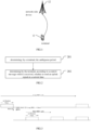
- the network structure includes a terminal 11 and a network-side device 12, where the terminal 11 may be a User Equipment (UE) or other terminal devices, for example: terminal side devices such as a Mobile phone, a Tablet Personal Computer (Tablet Personal Computer), a Laptop Computer (Laptop Computer), a Personal Digital Assistant (PDA), a Mobile Internet Device (MID), or a Wearable Device (Wearable Device) are not limited to specific types of terminals in the embodiments of the present disclosure.
- UE User Equipment
- terminal side devices such as a Mobile phone, a Tablet Personal Computer (Tablet Personal Computer), a Laptop Computer (Laptop Computer), a Personal Digital Assistant (PDA), a Mobile Internet Device (MID), or a Wearable Device (Wearable Device) are not limited to specific types of terminals in the embodiments of the present disclosure.
- the network-side device 12 may be a base station, for example: macro station, LTE eNB, 5G NR NB, and the like; the network-side device may also be a small station, such as a Low Power Node (LPN), pico, femto, or the network-side device may be an Access Point (AP); the base station may also be a network node composed of a Central Unit (CU) and a plurality of Transmission Reception Points (TRPs) whose management is and controls. It should be noted that, in the embodiment of the present disclosure, the specific type of the network-side device is not limited.
- LPN Low Power Node
- AP Access Point
- CU Central Unit
- TRPs Transmission Reception Points
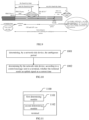
- FIG. 2 is a flowchart of a method of determining an ambiguous period in an embodiment of the present disclosure, as shown in FIG. 2 , the method includes the following steps:
- 201 determining, by a terminal, the ambiguous period, where the ambiguous period corresponds to a processing time for a PDCCH, or the ambiguous period corresponds to a processing time for an MAC CE;
- 202 determining by the terminal, according to a control message which is received, whether to send an uplink signal at a current time, where a difference between a receiving time of the control message and the current time is greater than or equal to the ambiguous period.
- the ambiguous period corresponds to a processing time for a Physical Downlink Control Channel, PDCCH, or the ambiguous period is based on at least a processing time for a Media Access Control Control Element, MAC CE and a K1, wherein the K1 is a time interval between a Physical Downlink Shared Channel, PDSCH, and a Hybrid Automatic Repeat reQuest, HARQ, feedback corresponding to the PDSCH.
- the ambiguous period may refer to a duration during in the network-side device and the terminal understand inconsistently whether the terminal is currently in Active Time.
- the processing time for PDCCH may be the time required for the terminal to process the PDCCH, for example: the processing time for PDCCH includes a parsing time of the PDCCH.
- the processing time for PDCCH may be configured in advance by the terminal, or defined in the protocol, or configured by the network-side device for the terminal in advance, and the like, which is not limited herein.
- the correspondence between the ambiguous period and the processing time for the PDCCH may be understood as that there is a certain relationship between the ambiguous period and the processing time for the PDCCH, for example: in some embodiments, the ambiguous period is equal to the processing time for the PDCCH, thereby avoiding the inconsistent understanding of the network-side device and the terminal for the Active Time of the terminal due to the processing time for the PDCCH, avoiding the unnecessary blind detection of the network-side device, and the improving the communication performance of the wireless communication system.
- the processing time for the MAC CE may be a time taken for the terminal to process the MAC CE, for example: the processing time for the MAC CE includes a parsing time of the MAC CE. It should be noted that, in the embodiment of the present disclosure, the processing time for the MAC CE may be a fixed value, for example: 0.5ms or 0ms, and specifically, in a case that the terminal is able to complete the analysis of the MAC CE within the time interval between the PDSCH and the HARQ feedback corresponding thereto, it may be determined that the processing time for the MAC CE is 0ms, because the terminal does not need to occupy additional time for processing the MAC CE in this case.
- the correspondence between the ambiguous period and the processing time for the MAC CE can be understood as that there is a correspondence between the ambiguous period and the processing time for the MAC CE, for example: the ambiguous period is equal to the sum of the processing time for the MAC CE and a fixed value, or the ambiguous period is equal to the sum of K0, K1 and the processing time for the MAC CE, where K0 is the time interval between a PDCCH and a PDSCH scheduled by the PDCCH, and K1 is the time interval between the PDSCH and a HARQ feedback corresponding thereto.
- the ambiguous period corresponds to the processing time for the MAC CE, thereby avoiding the inconsistent understanding of the network-side device and the terminal for the Active Time of the terminal, avoiding the unnecessary blind detection of the network-side device, and the improving the communication performance of the wireless communication system.
- the terminal determining whether to send the uplink signal transmission at the current time according to the control message which is received by the terminal may include: at a time N, determining whether to send the uplink signal transmission according to the control message received before subtracting the ambiguous period from the time N, where the time N is the current time and may also be understood as the performing time of step 202.
- the ambiguous period is 10ms
- whether to send the uplink signal is determined according to the control message received 10ms before the time N.
- control message includes:
- the DRX MAC CE may include a conventional DRX MAC CE or a long DRX MAC CE, which is not limited herein, for example: it may also be a short DRX MAC CE.
- the uplink message may also include other messages, such as: HARQ Acknowledgement (ACK)/Negative Acknowledgement (NACK), and the like.
- ACK HARQ Acknowledgement
- NACK Negative Acknowledgement
- the determining by the terminal, according to the claimed invention and according to the control message which is received, whether to send the uplink signal at the current time includes:
- whether CSI or SRS is sent at the current time is determined according to the control message received before subtracting the ambiguous period from the time N, so that it is able to avoid the inconsistent understanding of the network-side device and the terminal for whether the terminal sends the CSI or SRS, thereby realizing an accurate transmission of CSI and SRS between the network-side device and the terminal, avoiding the unnecessary blind detection of the network-side device, and improving the communication performance of the wireless communication system.
- the inconsistent understanding of the network-side device and the terminal for the Active Time of the terminal may be avoided through steps 201 and 202, so that uplink message transmission is performed according to the result determined in step 202, thereby ensuring that the CSI, SRS, ACK, or NACK messages may be correctly transmitted between the network-side device and the terminal, and also avoiding unnecessary blind detection, saving the power consumption.
- the determining by the terminal the ambiguous period includes: determining the ambiguous period by the terminal, according to at least one of a content carried by the PDCCH and a Channel State Information (CSI) masking configuration.
- CSI Channel State Information
- the content carried by the PDCCH may be PDCCH scheduling content, for example: UL grant or downlink scheduling
- the CSI masking configuration may be a terminal CSI masking configuration, for example: the terminal is configured with the CSI masking, or the terminal is not configured with the CSI masking.
- determining the ambiguous period according to at least one of the content carried by the PDCCH and the CSI masking configuration is understood as determining the ambiguous period according to the content carried by the PDCCH or the CSI masking configuration, and determines the ambiguous period according to the content carried by the PDCCH and the CSI masking configuration .
- the ambiguous period is determined according to at least one of the content carried by the PDCCH and the CSI masking configuration, it is able to determine different ambiguous periods for different scenarios, thereby improving the accuracy of the ambiguous period.
- the determining the ambiguous period by the terminal according to at least one of the content carried by the PDCCH and the CSI masking configuration includes:
- the time interval between the PDCCH and a PDSCH scheduled by the PDCCH may also be referred to as the timing relationship between the PDCCH of DL assignment and the PDSCH scheduled by the PDCCH, and the time interval between the PDSCH and a HARQ feedback corresponding to the PDSCH may also be referred to as the timing relationship between the PDSCH and the HARQ ACK/HARQ NACK feedback corresponding to the PDSCH.
- the ambiguous period is determined to be equal to the processing time for the PDCCH, thereby avoiding the inconsistent understanding of the network-side device and the terminal for the Active Time of the terminal due to the processing time for the PDCCH, ensuring that the uplink messages such as CSI, SRS, ACK, NACK may be correctly transmitted between the network-side device and the terminal, and also avoiding unnecessary blind detection, saving the power consumption.
- the ambiguous period is determined to be equal to the sum of K0, K1 and the processing time for the MAC CE, that is, in this case, the ambiguous period is equal to K0+ K1+ processing time for the MAC CE, thereby avoiding the inconsistent understanding of the network-side device and the terminal for the Active Time of the terminal due to the receiving time of the PDSCH and the processing time for the MAC CE, ensuring that the uplink messages such as CSI, SRS, ACK, NACK may be correctly transmitted between the network-side device and the terminal, and also avoiding unnecessary blind detection, saving the power consumption.
- the ambiguous period is determined to be equal to the sum of K1 and the processing time for the MAC CE. That is, the terminal is configured with the CSI masking, and regardless of the content scheduled by the PDCCH, the ambiguous period is equal to K1+ processing time for the MAC CE.
- the uplink messages such as CSI, SRS, ACK, NACK may be correctly transmitted between the network-side device and the terminal, and also avoid unnecessary blind detection, save the power consumption.
- the determining by the terminal the ambiguous period includes:
- the ambiguous period may be fixed to the sum of K0, K1 and the processing time for the MAC CE, that is, regardless of the content carried by the PUCCH and whether the terminal is configured with the CSI masking, the ambiguous period is always equal to K0+ K1+ processing time for the MAC CE, thereby avoiding the inconsistent understanding of the network-side device and the terminal for the Active Time of the terminal, ensuring that the uplink messages such as CSI, SRS, ACK, NACK may be correctly transmitted between the network-side device and the terminal, and also avoiding unnecessary blind detection, saving the power consumption.
- a value of the K0 is a maximum value of the K0 allowed by a Radio Resource Control (RRC) signaling configuration, or the value of the K0 is a fixed value which is a duration required by a Bandwidth Part (BWP) change.
- RRC Radio Resource Control
- BWP Bandwidth Part
- the K0 is the dration (e.g. 2ms) required by the BWP change, thereby at least avoiding the inconsistent understanding of the network-side device and the terminal for the Active Time of the terminal due to the BWP change.
- the K1 is a maximum K1 value allowed by RRC configuration signaling configuration, or the K1 is a fixed value.
- the maximum K1 value allowed by the RRC configuration signaling configuration is used, thereby avoiding the inconsistent understanding of the network-side device and the terminal for the Active Time of the terminal.
- the fixed value may be 1ms, or other fixed values defined in the protocol, and since the value K1 may be a fixed value, the complexity of determining the ambiguous period may be reduced to some extent.
- the processing time for the MAC CE value is a fixed value.
- the processing time for the MAC CE is a fixed value other than zero, for example: 0.5 ms.
- the processing time for the MAC CE is 0 ms.
- the processing time for the MAC CE is a fixed value (for example, if the MAC CE In this embodiment cannot be completed within the K1, the processing time for the MAC CE is a fixed value other than zero, and conversely, is 0 ms), thereby avoiding the inconsistent understanding of the network-side device and the terminal for the Active Time of the terminal due to the processing time for the MAC CE.
- a terminal determines an ambiguous period, wherein the ambiguous period corresponds to a processing time for a PDCCH, or the ambiguous period corresponds to a processing time for an MAC CE; and the terminal determines whether to send the uplink signal at the current time according to the control message which is received, where the difference between the receiving time of the control message and the current time is greater than or equal to the ambiguous period. Therefore, whether the uplink message is sent may be determined according to the ambiguous period, so that transmission errors between the network-side device and the terminal may be reduced, the communication performance of the wireless communication system may be improved, and unnecessary blind detection of the network-side device may be avoided.
- Example 1 the terminal is not configured with the CSI masking.
- the PDCCH is received before the on duration timer ends, and a DRX MAC CE is scheduled to allow the terminal to switch from long DRX to short DRX.
- the K1 value can be obtained by the following methods:
- the MAC CE value can be obtained by the following methods:
- the ambiguous period diagram is as shown in FIG. 4 , the PDCCH transmits a Cell Radio Network Temporary identity (C-RNTI), the on duration timer is stopped by a timer expiry, wherein the ambiguous period is equal to the processing time for the PDCCH (PDCCH processing time), after the ambiguous period expires, it is determined whether to perform a New uplink transmission, if so, a Start drx-Inactivity Timer (Start _ Inactivity) is started, so that CSI and a/N are clear (CSI and a/N: no ambiguity) in a time interval of K1 and a part of K0 (minus the ambiguous period), where A represents ACK and N represents NACK.
- C-RNTI Cell Radio Network Temporary identity
- Start drx-Inactivity Timer Start drx-Inactivity Timer
- Fig. 5 shows a schematic view of the ambiguous period in other cases, and the ambiguous period is divided into two segments: one segment is the processing time for the PDCCH, the other is the time after the drx-inactivity timer times out until the MAC CE is parsed, but for simplicity, the PDCCH may be unified for a period of time, the starting point thereof is the PDCCH receiving time, and the end point thereof is the time when the MAC CE is successfully parsed.
- the downlink shared channel transmission (DL-SCH 1st Tx) is performed, and the drx-Inactivity Timer (Stop drx-Inactivity Timer) is stopped.
- the network side cannot determine the transmission format used for HARQ ACK/NACK and CSI transmission.
- Example 2 the terminal is configured with the CSI masking.
- the PDCCH is received before the on duration Timer ends, and the DRX MAC CE is scheduled to switch the terminal from long DRX to short DRX.
- the ambiguous period T3 is equal to K1+ processing time for the MAC CE.
- the calculation mode of each parameter value is as follows: the K1 value can be taken as follows:
- the terminal does not report the CSI during the on duration, and there is no inconsistent understanding between the base station and the terminal for whether CSI is reported, and it is only needed to consider whether ACK/NACK is ambiguous, where the starting point of the ambiguous period is the PDSCH receiving time and the ending point is the time when the MAC CE is successfully parsed.
- Example 3 fixed length of ambiguous period
- the PDCCH is received before the on duration Timer ends, and a DRX MAC CE is scheduled to switch the terminal from long DRX to short DRX.
- the ambiguous periods are all set to K0+ K1+ processing time for the MAC CE.
- the calculation mode of each parameter value is as follows: the K0 value can be taken as follows:
- FIG. 9 a schematic view of the ambiguous period is shown in FIG. 9 , where the ambiguous period is divided into two segments: one segment is the processing time for the PDCCH, the other segment is the time after the drx-inactivity timer times out until the MAC CE is parsed, but for simplicity, the PDCCH can be unified for a period of time, the starting point is the PDCCH receiving time, and the end point is the time when the MAC CE is successfully parsed.
- FIG. 10 is another flowchart of a method of determining an ambiguous period in an embodiment of the present disclosure, as shown in FIG. 10 , the method includes the following steps:
- the determining by the network-side device the ambiguous period includes: determining the ambiguous period by the network-side device, according to at least one of a content carried by the PDCCH and a Channel State Information (CSI) masking configuration.
- CSI Channel State Information
- the determining the ambiguous period by the network-side device according to at least one of the content carried by the PDCCH and the CSI masking configuration includes:
- the determining by the network-side device the ambiguous period includes:
- a value of the K0 is a maximum value of the K0 allowed by a Radio Resource Control (RRC) signaling configuration, or the value of the K0 is a fixed value which is a duration required by a Bandwidth Part (BWP) change;
- RRC Radio Resource Control
- BWP Bandwidth Part
- control message includes:
- the determining by the network-side device, according to the control message sent to the terminal, whether the terminal sends the uplink signal at the current time includes:
- the above embodiment is used as an the embodiment of the network-side device corresponding to the embodiment shown in FIG. 2 , and specific embodiment thereof may refer to relevant descriptions of the embodiment shown in FIG. 2 , so in order to avoid repeated descriptions, this embodiment is not described again, and the same beneficial effects may also be achieved.
- FIG. 11 is a structural diagram of a terminal in an embodiment of the present disclosure, and as shown in FIG. 11 , a terminal 1100 includes:
- the first determining module 1101 is configured to determine the ambiguous period, according to at least one of a content carried by the PDCCH and a Channel State Information (CSI) masking configuration.
- CSI Channel State Information
- the first determining module 1101 is configured to:
- the first determining module 1101 is configured to determine that the ambiguous period is equal to a sum of K0, K1 and the processing time for the MAC CE; where the K0 is a time interval between the PDCCH and a PDSCH scheduled by the PDCCH, and the K1 is a time interval between the PDSCH and a HARQ feedback corresponding to the PDSCH.
- a value of the K0 is a maximum value of the K0 allowed by a Radio Resource Control (RRC) signaling configuration, or the value of the K0 is a fixed value which is a duration required by a Bandwidth Part (BWP) change;
- RRC Radio Resource Control
- BWP Bandwidth Part
- control message includes:
- the second determining module 1102 is configured to
- the terminal 1100 may be any terminal in the method embodiment in the embodiment of the present disclosure, and any embodiment of the terminal in the method embodiment in the embodiment of the present disclosure may be implemented by the terminal 1100 in this embodiment to achieve the same beneficial effect, and details thereof are not repeated here.
- FIG. 12 is a structural diagram of a network-side device in an embodiment of the present disclosure, and as shown in FIG. 12 , a network-side device 1200 includes:
- the first determining module 1201 is configured to determine the ambiguous period, according to at least one of a content carried by the PDCCH and a Channel State Information (CSI) masking configuration.
- CSI Channel State Information
- the first determining module 1201 is configured to:
- the first determining module 1201 is configured to determine that the ambiguous period is equal to a sum of K0, K1 and the processing time for the MAC CE; where the K0 is a time interval between the PDCCH and a PDSCH scheduled by the PDCCH, and the K1 is a time interval between the PDSCH and a HARQ feedback corresponding to the PDSCH.
- a value of the K0 is a maximum value of the K0 allowed by a Radio Resource Control (RRC) signaling configuration, or the value of the K0 is a fixed value which is a duration required by a Bandwidth Part (BWP) change;
- RRC Radio Resource Control
- BWP Bandwidth Part
- control message includes:
- the second determining module 1202 is configured to:
- the network-side device 1200 may be any network-side device in the method embodiment in the embodiment of the present disclosure, and any embodiment of the network-side device in the method embodiment in the embodiment of the present disclosure may be implemented by the network-side device 1200 in this embodiment to achieve the same beneficial effect, and details thereof are not repeated here.
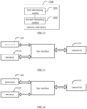
- FIG. 13 is a another structural diagram of a terminal in an embodiment of the present disclosure, and as shown in FIG. 13 , the terminal includes: a transceiver 1310, a memory 1320, a processor 1300, and a program stored in the memory 1320 and executable on the processor 1200, the processor 1300 is configured to read the program in the memory 1320 to perform:
- the transceiver 1310 is configured to to receive and transmit data under the control of the processor 1300.
- the bus architecture may include any number of interconnected buses and bridges, with various circuits representing one or more processors, in particular processor 1300, and memory, in particular memory 1320.
- the bus architecture may also link together various other circuits such as peripherals, voltage regulators, power management circuits, and the like, which are well known in the art, and therefore, will not be described any further herein.
- the bus interface provides an interface.
- the transceiver 1310 can be a number of elements including a transmitter and receiver that provide a means for communicating with various other apparatus over a transmission medium.
- the processor 1300 is responsible for managing the bus architecture and general processing, and the memory 1320 may store data used by the processor 1300 in performing operations.
- the memory 1320 is not limited to being implemented on a terminal, and the memory 1320 and the processor 1300 may be separated and located in different geographical locations.
- the determining the ambiguous period includes: determining the ambiguous period, according to at least one of a content carried by the PDCCH and a Channel State Information (CSI) masking configuration.
- CSI Channel State Information
- the determining the ambiguous period according to at least one of the content carried by the PDCCH and the CSI masking configuration includes:
- the determining the ambiguous period includes:
- a value of the K0 is a maximum value of the K0 allowed by a Radio Resource Control (RRC) signaling configuration, or the value of the K0 is a fixed value which is a duration required by a Bandwidth Part (BWP) change;
- RRC Radio Resource Control
- BWP Bandwidth Part
- control message includes:
- the determining, according to the control message which is received, whether to send the uplink signal at the current time includes:
- the terminal may be any terminal in the method embodiment in the embodiment of the present disclosure, and any embodiment of the terminal in the method embodiment in the embodiment of the present disclosure may be implemented by the terminal in this embodiment to achieve the same beneficial effect, and details thereof are not repeated here.
- FIG. 7 is another schematic view of an ambiguous period in an embodiment of the present disclosure, and as shown in FIG. 7 , the network-side device includes: a transceiver 710, a memory 720, a processor 700, and a program stored in the memory 720 and executable on the processor, the processor 1400 is configured to read the program in the memory 1420 to perform:
- the transceiver 710 is configured to receive and transmit data under the control of the processor 700.
- the bus architecture may include any number of interconnected buses and bridges, with various circuits being linked together, in particular, one or more processors, represented by processor 700, and memory, represented by memory 720.
- the bus architecture may also link together various other circuits such as peripherals, voltage regulators, power management circuits, and the like, which are well known in the art, and therefore, will not be described any further herein.
- the bus interface provides an interface.
- the transceiver 710 may be a plurality of elements including a transmitter and a receiver that provide a means for communicating with various other apparatus over a transmission medium.
- the processor 700 is responsible for managing the bus architecture and general processing, and the memory 720 may store data used by the processor 700 in performing operations.
- the memory 720 is not limited to be on the network-side device, and the memory 720 and the processor 700 may be separated and located in different geographical locations.
- the determining the ambiguous period includes: determining the ambiguous period, according to at least one of a content carried by the PDCCH and a Channel State Information (CSI) masking configuration.
- CSI Channel State Information
- the determining the ambiguous period according to at least one of the content carried by the PDCCH and the CSI masking configuration includes:
- the determining the ambiguous period includes:
- a value of the K0 is a maximum value of the K0 allowed by a Radio Resource Control (RRC) signaling configuration, or the value of the K0 is a fixed value which is a duration required by a Bandwidth Part (BWP) change;
- RRC Radio Resource Control
- BWP Bandwidth Part
- control message includes:
- the determining, according to the control message sent to the terminal, whether the terminal sends the uplink signal at the current time includes:
- the network-side device may be any network-side device in the method embodiment in the embodiment of the present disclosure, and any embodiment of the network-side device in the method embodiment in the embodiment of the present disclosure may be implemented by the network-side device in this embodiment to achieve the same beneficial effect, and details thereof are not repeated here.
- a computer-readable storage medium is further in an embodiment of the present disclosure, where a computer program is stored in the computer-readable storage medium, where the program is executed by a processor to perform the method of determining the ambiguous period at the terminal side, or the program is executed by the processor to perform the method of determining the ambiguous period at the network-side device side.
- the disclosed method and apparatus may be implemented in other manners.
- the above-described apparatus embodiments are merely illustrative, and for example, the division of the units is only one type of logical functional division, and other divisions may be realized in practice, for example, multiple units or components may be combined or integrated into another system, or some features may be omitted, or not executed.
- the shown or discussed mutual coupling or direct coupling or communication connection may be an indirect coupling or communication connection through some interfaces, devices or units, and may be in an electrical, mechanical or other form.
- functional units in the embodiments of the present disclosure may be integrated into one processing unit, or each unit may be separately and physically included, or two or more units may be integrated into one unit.
- the integrated unit may be implemented in the form of hardware, or in the form of hardware plus a software functional unit.
- the integrated unit implemented in the form of a software functional unit may be stored in a computer-readable storage medium.
- the software functional unit is stored in a storage medium and includes several instructions to enable a computer device (which may be a personal computer, a server, or a network device, etc.) to execute some steps of the method of processing the information data block according to various embodiments of the present disclosure.
- the aforementioned storage medium includes: a U-disk, a portable hard disk, a Read-Only Memory (ROM), a Random Access Memory (RAM), a magnetic disk or an optical disk, and other media capable of storing program codes.
Landscapes
- Engineering & Computer Science (AREA)
- Signal Processing (AREA)
- Computer Networks & Wireless Communication (AREA)
- Quality & Reliability (AREA)
- Mobile Radio Communication Systems (AREA)
Claims (14)
- Verfahren zur Bestimmung einer mehrdeutigen Periode, dadurch gekennzeichnet, dass das Verfahren umfasst:Bestimmen (201) der mehrdeutigen Periode durch ein Endgerät, wobei die mehrdeutige Periode einer Verarbeitungszeit für einen Physikalischen Downlink Steuerkanal, PDCCH, entspricht oder die mehrdeutige Periode auf mindestens einer Verarbeitungszeit für ein Medienzugangssteuerung-Steuerelement, MAC CE, und einem K1 basiert, wobei der K1 ein Zeitintervall zwischen einem Physikalischen Downlink Shared Kanal, PDSCH, und einer Hybriden Automatischen Wiederholungsanfrage, HARQ, Rückmeldung entsprechend dem PDSCH ist; undBestimmen (202) durch das Endgerät gemäß einer empfangenen Steuermeldung, ob ein Uplink-Signal derzeit zu senden ist, wobei eine Differenz zwischen einer Empfangszeit der Steuermeldung und der aktuellen Zeit größer oder gleich der mehrdeutigen Periode ist;wobei die Steuermeldung umfasst:mindestens eines von einer Downlink-Scheduling-Signalisierung, einer Uplink-Scheduling-Signalisierung, einer Scheduling-Anfrage und einem Diskontinuierlichen Empfang, DRX, MAC CE;das Uplink-Signal mindestens eines von CSI und einem Sounding Referenzsignal, SRS, umfasst;wobei das Bestimmen (202) durch das Endgerät gemäß der empfangenen Steuermeldung, ob das Uplink-Signal derzeitig zu senden ist, umfasst:Bestimmen durch das Endgerät gemäß der empfangenen Steuermeldung, ob die aktuelle Zeit eine DRX-Aktivzeit ist, und Nicht-Senden der SRS durch das Endgerät in dem Fall, dass die aktuelle Zeit nicht die DRX-Aktivzeit ist; oderin einem Fall, dass das Endgerät mit einer CSI-Maskierung konfiguriert ist, Bestimmen durch das Endgerät gemäß der empfangenen Steuermeldung, ob ein Dauer-Zeitgeber derzeit läuft, und Nicht-Senden der CSI durch das Endgerät in einem Fall, dass der Dauer-Zeitgeber nicht läuft; oderin einem Fall, dass das Endgerät nicht mit der CSI-Maskierung konfiguriert ist, Bestimmen durch das Endgerät gemäß der empfangenen Steuermeldung, ob die aktuelle Zeit die DRX-Aktivzeit ist, und Nicht-Senden der CSI durch das Endgerät in dem Fall, dass die aktuelle Zeit nicht die DRX-Aktivzeit ist;wobei das Bestimmen (201) der mehrdeutigen Periode durch das Endgerät umfasst:
Bestimmen der mehrdeutigen Periode durch das Endgerät gemäß mindestens einem von einem Inhalt, der von der PDCCH übertragen wird, und einer Kanalzustandsinformation, CSI, die die Konfiguration maskiert. - Verfahren nach Anspruch 1, wobei das Bestimmen der mehrdeutigen Periode durch das Endgerät gemäß mindestens einem von einem Inhalt, der durch den PDCCH übertragen wird, und der CSI-Maskierungskonfiguration umfasst:in einem Fall, dass das Endgerät nicht mit der CSI-Maskierung konfiguriert ist und der vom PDCCH übertragene Inhalt ein Uplink, UL, Gewährung ist, Bestimmen durch das Endgerät, dass die mehrdeutige Periode gleich der Verarbeitungszeit für den PDCCH ist; oderin dem Fall, dass das Endgerät nicht mit der CSI-Maskierung konfiguriert ist und der von der PDCCH übertragene Inhalt eine Downlink-, DL-, Zuweisung ist, Bestimmen durch das Endgerät, dass die mehrdeutige Periode gleich einer Summe eines K0, des K1 und der Verarbeitungszeit für den MAC CE ist; oderin einem Fall, dass das Endgerät mit der CSI-Maskierung konfiguriert ist, Bestimmen durch das Endgerät, dass die mehrdeutige Periode gleich einer Summe des K1 und der Verarbeitungszeit für den MAC CE ist;wobei K0 ein Zeitintervall zwischen dem PDCCH und dem vom PDCCH festgelegten PDSCH ist.
- Verfahren nach Anspruch 2, wobei ein Wert des K0 ein Maximalwert des K0 ist, der durch eine Funkressourcensteuerung-RRC-Signalisierungskonfiguration erlaubt ist, oder der Wert des K0 ein Festwert ist, der eine durch einen Bandbreitenteil erforderliche Dauer ist;wobei ein Wert des K1 ein Maximalwert des K1 ist, der durch die RRC-Signalisierungskonfiguration erlaubt ist, oder der K1 ein Festwert ist;ein Wert der Verarbeitungszeit für den MAC CE ein Festwert ist.
- Verfahren zur Bestimmung einer mehrdeutigen Periode, dadurch gekennzeichnet, dass das Verfahren umfasst:Bestimmen (1001) der mehrdeutigen Periode durch eine netzseitige Vorrichtung, wobei die mehrdeutige Periode einer Verarbeitungszeit für einen Physikalischen Downlink Steuerkanal, PDCCH, entspricht oder die mehrdeutige Periode auf mindestens einer Verarbeitungszeit für ein Medienzugangssteuerung-Steuerelement, MAC CE, und einem K1 basiert, wobei der K1 ein Zeitintervall zwischen einem Physikalischen Downlink Shared Kanal, PDSCH, und einer Hybriden Automatischen Wiederholungsanfrage, HARQ, Rückmeldung entsprechend dem PDSCH ist; undBestimmen (1002) durch die netzseitige Vorrichtung gemäß einer an ein Endgerät gesendeten Steuermeldung, ob das Endgerät ein Uplink-Signal derzeit sendet, wobei eine Differenz zwischen einer Empfangszeit der Steuermeldung und der aktuellen Zeit größer oder gleich der mehrdeutigen Periode ist;wobei die Steuermeldung umfasst:mindestens eines von einer Downlink-Scheduling-Signalisierung, einer Uplink-Scheduling-Signalisierung, einer Scheduling-Anfrage und einem Diskontinuierlichen Empfang, DRX, MAC CE;das Uplink-Signal mindestens eines von CSI und einem Sounding Referenzsignal, SRS, umfasst;wobei das Bestimmen (1002) durch die netzseitige Vorrichtung gemäß der an das Endgerät gesendeten Steuermeldung, ob das Endgerät das Uplink-Signal derzeit sendet, umfasst:Bestimmen durch die netzseitige Vorrichtung, gemäß der an das Endgerät gesendeten Steuermeldung, ob die aktuelle Zeit eine DRX-Aktivzeit ist, und Bestimmen durch die netzseitige Vorrichtung, dass das Endgerät die SRS in einem Fall, dass die aktuelle Zeit nicht die DRX-Aktivzeit ist, nicht sendet; oderin einem Fall, dass das Endgerät mit einer CSI-Maskierung konfiguriert ist, Bestimmen durch die netzseitige Vorrichtung gemäß der an das Endgerät gesendeten Steuermeldung, ob ein Dauer-Zeitgeber derzeit läuft, und Bestimmen durch die netzseitige Vorrichtung, dass das Endgerät die CSI, in einem Fall, dass der Dauer-Zeitgeber nicht läuft, nicht sendet; oderin einem Fall, dass das Endgerät nicht mit der CSI-Maskierung konfiguriert ist, Bestimmen durch die netzseitige Vorrichtung gemäß der an das Endgerät gesendeten Steuermeldung, ob die aktuelle Zeit die DRX-Aktivzeit ist, und Bestimmen durch die netzseitige Vorrichtung, dass das Endgerät die CSI, in dem Fall, dass die aktuelle Zeit nicht die DRX-Aktivzeit ist, nicht sendet;wobei das Bestimmen (1001) der mehrdeutigen Periode durch die netzseitige Vorrichtung umfasst:
Bestimmen der mehrdeutigen Periode durch die netzseitige Vorrichtung gemäß mindestens einem von einem Inhalt, der von der PDCCH übertragen wird, und einer Kanalzustandsinformation, CSI, und einer Maskierungskonfiguration. - Verfahren nach Anspruch 4, wobei das Bestimmen der mehrdeutigen Periode durch die netzseitige Vorrichtung gemäß mindestens einem von dem Inhalt, der von dem PDCCH übertragen wird, und der CSI-Maskierungskonfiguration umfasst:in einem Fall, dass das Endgerät nicht mit der CSI-Maskierung konfiguriert ist und der vom PDCCH übertragene Inhalt ein Uplink, UL, Gewährung ist, Bestimmen durch die netzseitige Vorrichtung, dass die mehrdeutige Periode gleich der Verarbeitungszeit für den PDCCH ist; oderin dem Fall, dass das Endgerät nicht mit der CSI-Maskierung konfiguriert ist und der vom PDCCH übertragene Inhalt eine Downlink-, DL-, Zuweisung ist, Bestimmen durch die netzseitige Vorrichtung, dass die mehrdeutige Periode gleich einer Summe eines K0, des K1 und der Verarbeitungszeit für den MAC CE ist; oderin einem Fall, dass das Endgerät mit der CSI-Maskierung konfiguriert ist, Bestimmen durch die netzseitige Vorrichtung, dass die mehrdeutige Periode gleich einer Summe des K1 und der Verarbeitungszeit für den MAC CE ist;wobei K0 ein Zeitintervall zwischen dem PDCCH und dem vom PDCCH festgelegten PDSCH ist.
- Verfahren nach Anspruch 5, wobei ein Wert des K0 ein Maximalwert des K0 ist, der durch eine Funkressourcensteuerung-RRC-Signalisierungskonfiguration erlaubt ist, oder der Wert des K0 ein Festwert ist, der eine durch einen Bandbreitenteil erforderliche Dauer ist;wobei ein Wert des K1 ein Maximalwert des K1 ist, der durch die RRC-Signalisierungskonfiguration erlaubt ist, oder der K1 ein Festwert ist;ein Wert der Verarbeitungszeit für den MAC CE ein Festwert ist.
- Endgerät (1100), dadurch gekennzeichnet, dass das Endgerät (1100) umfasst:ein erstes Bestimmungsmodul (1101), das konfiguriert ist, um eine mehrdeutige Periode zu bestimmen, wobei die mehrdeutige Periode einer Verarbeitungszeit für einen Physikalischen Downlink Steuerkanal, PDCCH, entspricht oder die mehrdeutige Periode auf mindestens einer Verarbeitungszeit für ein Medienzugangssteuerung Steuerelement, MAC CE, und einem K1 basiert, wobei das K1 ein Zeitintervall zwischen einem Physikalischen Downlink Shared Kanal, PDSCH, und einer Hybriden Automatischen Wiederholungsanfrage, HARQ, Rückmeldung entsprechend dem PDSCH ist; undein zweites Bestimmungsmodul (1102), das konfiguriert ist, um gemäß einer empfangenen Steuermeldung zu bestimmen, ob ein Uplink-Signal derzeit zu senden ist, wobei eine Differenz zwischen einer Empfangszeit der Steuermeldung und der aktuellen Zeit größer oder gleich der mehrdeutigen Periode ist;wobei die Steuermeldung umfasst:mindestens eines von einer Downlink-Scheduling-Signalisierung, einer Uplink-Scheduling-Signalisierung, einer Scheduling-Anfrage und einem Diskontinuierlichen Empfang, DRX, MAC CE;das Uplink-Signal mindestens eines von CSI und einem Sounding Referenzsignal, SRS, umfasst;wobei das zweite Bestimmungsmodul (1102) ferner konfiguriert ist, um:gemäß der empfangenen Steuermeldung zu bestimmen, ob die aktuelle Zeit eine DRX-Aktivzeit ist, und die SRS nicht zu senden, wenn die aktuelle Zeit nicht die DRX-Aktivzeit ist; oderin einem Fall, dass das Endgerät mit einer CSI-Maskierung konfiguriert ist, gemäß der empfangenen Steuermeldung zu bestimmen, ob ein Dauer-Zeitgeber derzeit läuft, und die CSI nicht zu senden, wenn der Dauer-Zeitgeber nicht läuft; oderin einem Fall, dass das Endgerät nicht mit der CSI-Maskierung konfiguriert ist, gemäß der empfangenen Steuermeldung zu bestimmen, ob die aktuelle Zeit die DRX-Aktivzeit ist, und die CSI, nicht zu senden, wenn die aktuelle Zeit nicht die DRX-Aktivzeit ist;wobei das erste Bestimmungsmodul (1101) konfiguriert ist, um:
der mehrdeutigen Periode gemäß mindestens einem von einem Inhalt, der vom PDCCH übertragen wird, und einer Kanalzustandsinformation, CSI, als Maskierungskonfiguration zu bestimmen. - Netzseitige Vorrichtung (1200), dadurch gekennzeichnet, dass die netzseitige Vorrichtung (1200) umfasst:ein erstes Bestimmungsmodul (1201), das konfiguriert ist, um eine mehrdeutige Periode zu bestimmen, wobei die mehrdeutige Periode einer Verarbeitungszeit für einen Physikalischen Downlink Steuerkanal, PDCCH, entspricht oder die mehrdeutige Periode auf mindestens einer Verarbeitungszeit für ein Medienzugangssteuerung Steuerelement, MAC CE, und einem K1 basiert, wobei das K1 ein Zeitintervall zwischen einem Physikalischen Downlink Shared Kanal, PDSCH, und einer Hybriden Automatischen Wiederholungsanfrage, HARQ, Rückmeldung entsprechend dem PDSCH ist; undein zweites Bestimmungsmodul (1202), das konfiguriert ist, um gemäß einer an ein Endgerät gesendeten Steuermeldung zu bestimmen, ob das Endgerät ein Uplink-Signal derzeit sendet, wobei eine Differenz zwischen einer Empfangszeit der Steuermeldung und der aktuellen Zeit größer oder gleich der mehrdeutigen Periode ist;wobei die Steuermeldung umfasst:mindestens eines von einer Downlink-Scheduling-Signalisierung, einer Uplink-Scheduling-Signalisierung, einer Scheduling-Anfrage und einem Diskontinuierlichen Empfang, DRX, MAC CE;das Uplink-Signal mindestens eines von CSI und einem Sounding Referenzsignal, SRS, umfasst;wobei das zweite Bestimmungsmodul (1202) ferner konfiguriert ist, um:gemäß der an das Endgerät gesendeten Steuermeldung zu bestimmen, ob die aktuelle Zeit eine DRX-Aktivzeit ist, und zu bestimmen, dass das Endgerät die SRS in einem Fall, dass die aktuelle Zeit nicht die DRX-Aktivzeit ist, nicht sendet; oderin einem Fall, dass das Endgerät mit einer CSI-Maskierung konfiguriert ist, gemäß der an das Endgerät gesendeten Steuermeldung zu bestimmen, ob ein Dauer-Zeitgeber derzeit läuft, und zu bestimmen, dass das Endgerät die CSI in einem Fall, dass der Dauer-Zeitgeber nicht läuft, nicht sendet; oderin einem Fall, dass das Endgerät nicht mit der CSI-Maskierung konfiguriert ist, gemäß der an das Endgerät gesendeten Steuermeldung zu bestimmen, ob die aktuelle Zeit die DRX-Aktivzeit ist, und zu bestimmen, dass das Endgerät die CSI in einem Fall, dass die aktuelle Zeit nicht die DRX-Aktivzeit ist, nicht sendet;wobei das erste Bestimmungsmodul (1201) so konfiguriert ist, um:
der mehrdeutigen Periode gemäß mindestens einem von einem Inhalt, der vom PDCCH übertragen wird, und einer Kanalzustandsinformation, CSI, als Maskierungskonfiguration zu bestimmen. - Verfahren zur Bestimmung einer mehrdeutigen Periode, dadurch gekennzeichnet, dass das Verfahren umfasst:Bestimmen (201) der mehrdeutigen Periode durch ein Endgerät, wobei die mehrdeutige Periode einer Verarbeitungszeit für einen Physikalischen Downlink Steuerkanal, PDCCH, entspricht oder die mehrdeutige Periode auf mindestens einer Verarbeitungszeit für ein Medienzugangssteuerung-Steuerelement, MAC CE, und einem K1 basiert, wobei der K1 ein Zeitintervall zwischen einem Physikalischen Downlink Shared Kanal, PDSCH, und einer Hybriden Automatischen Wiederholungsanfrage, HARQ, Rückmeldung entsprechend dem PDSCH ist; undBestimmen (202) durch das Endgerät gemäß einer empfangenen Steuermeldung, ob ein Uplink-Signal derzeit zu senden ist, wobei eine Differenz zwischen einer Empfangszeit der Steuermeldung und der aktuellen Zeit größer oder gleich der mehrdeutigen Periode ist;wobei die Steuermeldung umfasst:mindestens eines von einer Downlink-Scheduling-Signalisierung, einer Uplink-Scheduling-Signalisierung, einer Scheduling-Anfrage und einem Diskontinuierlichen Empfang, DRX, MAC CE;das Uplink-Signal mindestens eines von CSI und einem Sounding Referenzsignal, SRS, umfasst;wobei das Bestimmen (202) durch das Endgerät gemäß der empfangenen Steuermeldung, ob das Uplink-Signal derzeitig zu senden ist, umfasst:Bestimmen durch das Endgerät gemäß der empfangenen Steuermeldung, ob die aktuelle Zeit eine DRX-Aktivzeit ist, und Nicht-Senden der SRS durch das Endgerät in dem Fall, dass die aktuelle Zeit nicht die DRX-Aktivzeit ist; oderin einem Fall, dass das Endgerät mit einer CSI-Maskierung konfiguriert ist, Bestimmen durch das Endgerät gemäß der empfangenen Steuermeldung, ob ein Dauer-Zeitgeber derzeit läuft, und Nicht-Senden der CSI durch das Endgerät in einem Fall, dass der Dauer-Zeitgeber nicht läuft; oderin einem Fall, dass das Endgerät nicht mit der CSI-Maskierung konfiguriert ist, Bestimmen durch das Endgerät gemäß der empfangenen Steuermeldung, ob die aktuelle Zeit die DRX-Aktivzeit ist, und Nicht-Senden der CSI durch das Endgerät in dem Fall, dass die aktuelle Zeit nicht die DRX-Aktivzeit ist;wobei das Bestimmen (201) der mehrdeutigen Periode durch das Endgerät umfasst:Bestimmen durch das Endgerät, dass die mehrdeutige Periode gleich einer Summe eines K0, des K1 und der Verarbeitungszeit für den MAC CE ist;wobei K0 ein Zeitintervall zwischen dem PDCCH und dem vom PDCCH festgelegten PDSCH ist.
- Verfahren nach Anspruch 9, wobei ein Wert des K0 ein Maximalwert des K0 ist, der durch eine Funkressourcensteuerung-RRC-Signalisierungskonfiguration erlaubt ist, oder der Wert des K0 ein Festwert ist, der eine durch einen Bandbreitenteil erforderliche Dauer ist;wobei ein Wert des K1 ein Maximalwert des K1 ist, der durch die RRC-Signalisierungskonfiguration erlaubt ist, oder der K1 ein Festwert ist;ein Wert der Verarbeitungszeit für den MAC CE ein Festwert ist.
- Verfahren zur Bestimmung einer mehrdeutigen Periode, dadurch gekennzeichnet, dass das Verfahren umfasst:Bestimmen (1001) der mehrdeutigen Periode durch eine netzseitige Vorrichtung, wobei die mehrdeutige Periode einer Verarbeitungszeit für einen Physikalischen Downlink Steuerkanal, PDCCH, entspricht oder die mehrdeutige Periode auf mindestens einer Verarbeitungszeit für ein Medienzugangssteuerung-Steuerelement, MAC CE, und einem K1 basiert, wobei der K1 ein Zeitintervall zwischen einem Physikalischen Downlink Shared Kanal, PDSCH, und einer Hybriden Automatischen Wiederholungsanfrage, HARQ, Rückmeldung entsprechend dem PDSCH ist; undBestimmen (1002) durch die netzseitige Vorrichtung gemäß einer an ein Endgerät gesendeten Steuermeldung, ob das Endgerät ein Uplink-Signal derzeit sendet, wobei eine Differenz zwischen einer Empfangszeit der Steuermeldung und der aktuellen Zeit größer oder gleich der mehrdeutigen Periode ist;wobei die Steuermeldung umfasst:mindestens eines von einer Downlink-Scheduling-Signalisierung, einer Uplink-Scheduling-Signalisierung, einer Scheduling-Anfrage und einem Diskontinuierlichen Empfang, DRX, MAC CE;das Uplink-Signal mindestens eines von CSI und einem Sounding Referenzsignal, SRS, umfasst;wobei das Bestimmen (1002) durch die netzseitige Vorrichtung gemäß der an das Endgerät gesendeten Steuermeldung, ob das Endgerät das Uplink-Signal derzeit sendet, umfasst:Bestimmen durch die netzseitige Vorrichtung, gemäß der an das Endgerät gesendeten Steuermeldung, ob die aktuelle Zeit eine DRX-Aktivzeit ist, und Bestimmen durch die netzseitige Vorrichtung, dass das Endgerät die SRS in einem Fall, dass die aktuelle Zeit nicht die DRX-Aktivzeit ist, nicht sendet; oderin einem Fall, dass das Endgerät mit einer CSI-Maskierung konfiguriert ist, Bestimmen durch die netzseitige Vorrichtung gemäß der an das Endgerät gesendeten Steuermeldung, ob ein Dauer-Zeitgeber derzeit läuft, und Bestimmen durch die netzseitige Vorrichtung, dass das Endgerät die CSI, in einem Fall, dass der Dauer-Zeitgeber nicht läuft, nicht sendet; oderin einem Fall, dass das Endgerät nicht mit der CSI-Maskierung konfiguriert ist, Bestimmen durch die netzseitige Vorrichtung gemäß der an das Endgerät gesendeten Steuermeldung, ob die aktuelle Zeit die DRX-Aktivzeit ist, und Bestimmen durch die netzseitige Vorrichtung, dass das Endgerät die CSI, in dem Fall, dass die aktuelle Zeit nicht die DRX-Aktivzeit ist, nicht sendet;Das Bestimmen (1001) der mehrdeutigen Periode durch die netzseitige Vorrichtung umfasst:Bestimmen durch die netzseitige Vorrichtung, dass die mehrdeutige Periode gleich einer Summe von einem K0, des K1 und der Verarbeitungszeit für den MAC CE ist;wobei K0 ein Zeitintervall zwischen dem PDCCH und dem vom PDCCH festgelegten PDSCH ist.
- Verfahren nach Anspruch 11, wobei ein Wert des K0 ein Maximalwert des K0 ist, der durch eine Funkressourcensteuerung-RRC-Signalisierungskonfiguration erlaubt ist, oder der Wert des K0 ein Festwert ist, der eine durch einen Bandbreitenteil erforderliche Dauer ist;wobei ein Wert des K1 ein Maximalwert des K1 ist, der durch die RRC-Signalisierungskonfiguration erlaubt ist, oder der K1 ein Festwert ist;ein Wert der Verarbeitungszeit für den MAC CE ein Festwert ist.
- Endgerät (1100), dadurch gekennzeichnet, dass das Endgerät (1100) umfasst:ein erstes Bestimmungsmodul (1101), das konfiguriert ist, um eine mehrdeutige Periode zu bestimmen, wobei die mehrdeutige Periode einer Verarbeitungszeit für einen Physikalischen Downlink Steuerkanal, PDCCH, entspricht oder die mehrdeutige Periode auf mindestens einer Verarbeitungszeit für ein Medienzugangssteuerung Steuerelement, MAC CE, und einem K1 basiert, wobei das K1 ein Zeitintervall zwischen einem Physikalischen Downlink Shared Kanal, PDSCH, und einer Hybriden Automatischen Wiederholungsanfrage, HARQ, Rückmeldung entsprechend dem PDSCH ist; undein zweites Bestimmungsmodul (1102), das konfiguriert ist, um gemäß einer empfangenen Steuermeldung zu bestimmen, ob ein Uplink-Signal derzeit zu senden ist, wobei eine Differenz zwischen einer Empfangszeit der Steuermeldung und der aktuellen Zeit größer oder gleich der mehrdeutigen Periode ist;wobei die Steuermeldung umfasst:mindestens eines von einer Downlink-Scheduling-Signalisierung, einer Uplink-Scheduling-Signalisierung, einer Scheduling-Anfrage und einem Diskontinuierlichen Empfang, DRX, MAC CE;das Uplink-Signal mindestens eines von CSI und einem Sounding Referenzsignal, SRS, umfasst;wobei das zweite Bestimmungsmodul (1102) ferner konfiguriert ist, um:gemäß der empfangenen Steuermeldung zu bestimmen, ob die aktuelle Zeit eine DRX-Aktivzeit ist, und die SRS nicht zu senden, wenn die aktuelle Zeit nicht die DRX-Aktivzeit ist; oderin einem Fall, dass das Endgerät mit einer CSI-Maskierung konfiguriert ist, gemäß der empfangenen Steuermeldung zu bestimmen, ob ein Dauer-Zeitgeber derzeit läuft, und die CSI nicht zu senden, wenn der Dauer-Zeitgeber nicht läuft; oderin einem Fall, dass das Endgerät nicht mit der CSI-Maskierung konfiguriert ist, gemäß der empfangenen Steuermeldung zu bestimmen, ob die aktuelle Zeit die DRX-Aktivzeit ist, und die CSI, nicht zu senden, wenn die aktuelle Zeit nicht die DRX-Aktivzeit ist;wobei das erste Bestimmungsmodul (1101) konfiguriert ist, um:Festzustellen, dass die mehrdeutige Periode gleich der Summe von einem K0, des K1 und der Verarbeitungszeit für den MAC CE ist;wobei K0 ein Zeitintervall zwischen dem PDCCH und dem vom PDCCH festgelegten PDSCH ist.
- Netzseitige Vorrichtung (1200), dadurch gekennzeichnet, dass die netzseitige Vorrichtung (1200) umfasst:ein erstes Bestimmungsmodul (1201), das konfiguriert ist, um eine mehrdeutige Periode zu bestimmen, wobei die mehrdeutige Periode einer Verarbeitungszeit für einen Physikalischen Downlink Steuerkanal, PDCCH, entspricht oder die mehrdeutige Periode auf mindestens einer Verarbeitungszeit für ein Medienzugangssteuerung Steuerelement, MAC CE, und einem K1 basiert, wobei das K1 ein Zeitintervall zwischen einem Physikalischen Downlink Shared Kanal, PDSCH, und einer Hybriden Automatischen Wiederholungsanfrage, HARQ, Rückmeldung entsprechend dem PDSCH ist; undein zweites Bestimmungsmodul (1202), das konfiguriert ist, um gemäß einer an ein Endgerät gesendeten Steuermeldung zu bestimmen, ob das Endgerät ein Uplink-Signal derzeit sendet, wobei eine Differenz zwischen einer Empfangszeit der Steuermeldung und der aktuellen Zeit größer oder gleich der mehrdeutigen Periode ist;wobei die Steuermeldung umfasst:mindestens eines von einer Downlink-Scheduling-Signalisierung, einer Uplink-Scheduling-Signalisierung, einer Scheduling-Anfrage und einem Diskontinuierlichen Empfang, DRX, MAC CE;das Uplink-Signal mindestens eines von CSI und einem Sounding Referenzsignal, SRS, umfasst;wobei das zweite Bestimmungsmodul (1202) ferner konfiguriert ist, um:gemäß der an das Endgerät gesendeten Steuermeldung zu bestimmen, ob die aktuelle Zeit eine DRX-Aktivzeit ist, und zu bestimmen, dass das Endgerät die SRS in einem Fall, dass die aktuelle Zeit nicht die DRX-Aktivzeit ist, nicht sendet; oderin einem Fall, dass das Endgerät mit einer CSI-Maskierung konfiguriert ist, gemäß der an das Endgerät gesendeten Steuermeldung zu bestimmen, ob ein Dauer-Zeitgeber derzeit läuft, und zu bestimmen, dass das Endgerät die CSI in einem Fall, dass der Dauer-Zeitgeber nicht läuft, nicht sendet; oderin einem Fall, dass das Endgerät nicht mit der CSI-Maskierung konfiguriert ist, gemäß der an das Endgerät gesendeten Steuermeldung zu bestimmen, ob die aktuelle Zeit die DRX-Aktivzeit ist, und zu bestimmen, dass das Endgerät die CSI in einem Fall, dass die aktuelle Zeit nicht die DRX-Aktivzeit ist, nicht sendet;wobei das erste Bestimmungsmodul (1201) konfiguriert ist, um:Festzustellen, dass die mehrdeutige Periode gleich der Summe von einem K0, des K1 und der Verarbeitungszeit für den MAC CE ist;wobei K0 ein Zeitintervall zwischen dem PDCCH und dem vom PDCCH festgelegten PDSCH ist.
Applications Claiming Priority (2)
| Application Number | Priority Date | Filing Date | Title |
|---|---|---|---|
| CN201810464472.0A CN110475392B (zh) | 2018-05-09 | 2018-05-09 | 一种模糊期长度确定方法、终端和网络侧设备 |
| PCT/CN2019/084507 WO2019214460A1 (zh) | 2018-05-09 | 2019-04-26 | 模糊期长度确定方法、终端和网络侧设备 |
Publications (3)
| Publication Number | Publication Date |
|---|---|
| EP3793324A1 EP3793324A1 (de) | 2021-03-17 |
| EP3793324A4 EP3793324A4 (de) | 2021-06-23 |
| EP3793324B1 true EP3793324B1 (de) | 2024-02-14 |
Family
ID=68467779
Family Applications (1)
| Application Number | Title | Priority Date | Filing Date |
|---|---|---|---|
| EP19799418.9A Active EP3793324B1 (de) | 2018-05-09 | 2019-04-26 | Einstellung der länge einer nicht vorhersagbaren periode |
Country Status (6)
| Country | Link |
|---|---|
| US (1) | US11284430B2 (de) |
| EP (1) | EP3793324B1 (de) |
| JP (1) | JP7216745B2 (de) |
| KR (2) | KR20230030031A (de) |
| CN (1) | CN110475392B (de) |
| WO (1) | WO2019214460A1 (de) |
Families Citing this family (2)
| Publication number | Priority date | Publication date | Assignee | Title |
|---|---|---|---|---|
| CN114124313A (zh) * | 2020-08-26 | 2022-03-01 | 华为技术有限公司 | 一种上报、接收csi的方法及对应装置 |
| WO2022099494A1 (en) * | 2020-11-11 | 2022-05-19 | Qualcomm Incorporated | Timeline-based transmission of sounding reference signal (srs) resources |
Family Cites Families (10)
| Publication number | Priority date | Publication date | Assignee | Title |
|---|---|---|---|---|
| CN102255696B (zh) | 2010-04-07 | 2016-03-30 | 华为技术有限公司 | 一种传输上行控制信息的方法、用户设备和基站 |
| CN102469506B (zh) | 2010-11-08 | 2014-06-11 | 华为技术有限公司 | 应答信息的传输方法、装置及系统 |
| CN105722195B (zh) * | 2011-01-28 | 2019-12-24 | 华为技术有限公司 | 一种非连续接收的方法和装置 |
| CN102740477B (zh) | 2011-03-31 | 2016-03-02 | 华为技术有限公司 | 时分双工系统中子帧配置的方法、基站及用户设备 |
| CN104080179B (zh) | 2013-03-29 | 2018-02-23 | 中国移动通信集团公司 | 长期演进时分双工系统中的业务传输方法、装置及系统 |
| WO2017221202A1 (en) * | 2016-06-23 | 2017-12-28 | Nokia Technologies Oy | Beam change |
| CN109952807B (zh) * | 2016-09-24 | 2020-07-10 | 欧芬诺有限责任公司 | 无线设备和无线网络中的非连续接收 |
| CN109586881B (zh) * | 2017-09-29 | 2021-11-12 | 株式会社Kt | 用于在新无线电中切换带宽部分的方法和装置 |
| CN110351056B (zh) * | 2018-04-04 | 2021-07-09 | 大唐移动通信设备有限公司 | 一种harq-ack消息的传输方法、终端及基站 |
| CN112737740A (zh) * | 2018-04-04 | 2021-04-30 | 华为技术有限公司 | 一种控制定时器的方法和装置 |
-
2018
- 2018-05-09 CN CN201810464472.0A patent/CN110475392B/zh active Active
-
2019
- 2019-04-26 KR KR1020237005807A patent/KR20230030031A/ko not_active Withdrawn
- 2019-04-26 EP EP19799418.9A patent/EP3793324B1/de active Active
- 2019-04-26 WO PCT/CN2019/084507 patent/WO2019214460A1/zh not_active Ceased
- 2019-04-26 US US17/054,110 patent/US11284430B2/en active Active
- 2019-04-26 KR KR1020207034897A patent/KR102502757B1/ko active Active
- 2019-04-26 JP JP2020562641A patent/JP7216745B2/ja active Active
Also Published As
| Publication number | Publication date |
|---|---|
| CN110475392B (zh) | 2021-06-15 |
| KR20210002720A (ko) | 2021-01-08 |
| JP2021521729A (ja) | 2021-08-26 |
| US11284430B2 (en) | 2022-03-22 |
| JP7216745B2 (ja) | 2023-02-01 |
| KR102502757B1 (ko) | 2023-02-21 |
| US20210250976A1 (en) | 2021-08-12 |
| CN110475392A (zh) | 2019-11-19 |
| WO2019214460A1 (zh) | 2019-11-14 |
| KR20230030031A (ko) | 2023-03-03 |
| EP3793324A4 (de) | 2021-06-23 |
| EP3793324A1 (de) | 2021-03-17 |
Similar Documents
| Publication | Publication Date | Title |
|---|---|---|
| US12250637B2 (en) | Methods for communication, terminal device, network device, and computer readable media | |
| US9668207B2 (en) | Deciding whether to send uplink control signaling based on the active time status of a user equipment configured with discontinuous reception (DRX) | |
| EP3298832B1 (de) | Aktivierung von drx-parametern | |
| EP4149191B1 (de) | Verfahren und vorrichtungen zur zeitbestimmung, chip und computerlesbares speichermedium | |
| WO2019137378A1 (zh) | 通信方法、通信设备和网络设备 | |
| CN106533633A (zh) | 信息处理方法、用户设备及基站 | |
| US11228933B2 (en) | Method for transmitting information and terminal device | |
| WO2017197949A1 (zh) | 一种数据传输的控制方法及相关设备 | |
| CN113950164B (zh) | 控制多个无线电接口上的非连续接收行为的方法和设备 | |
| EP4615063A1 (de) | Energiesparanweisungsverfahren und -vorrichtung | |
| EP3793324B1 (de) | Einstellung der länge einer nicht vorhersagbaren periode | |
| CN116709544A (zh) | 一种drx传输方法及相关设备 | |
| JPWO2020261461A5 (de) | ||
| EP4278699B1 (de) | Aktivierung einer frühen pdcch-reihenfolge zur pucch-scell-aktivierung | |
| EP4040860A1 (de) | Energiesparendes informationsübertragungsverfahren, endgerät und netzseitige vorrichtung | |
| WO2024065529A1 (en) | Methods and apparatuses for a pdcch monitoring enhancement mechanism for xr traffic | |
| CN111757377B (zh) | 一种直通链路监测方法和终端 | |
| CN120752994A (zh) | 非连续接收模式配置 | |
| WO2022078695A1 (en) | Method for fast scheduling of retransmission | |
| CN120548763A (zh) | 在小区不连续发送/不连续接收下的用户装备行为 |
Legal Events
| Date | Code | Title | Description |
|---|---|---|---|
| STAA | Information on the status of an ep patent application or granted ep patent |
Free format text: STATUS: THE INTERNATIONAL PUBLICATION HAS BEEN MADE |
|
| PUAI | Public reference made under article 153(3) epc to a published international application that has entered the european phase |
Free format text: ORIGINAL CODE: 0009012 |
|
| STAA | Information on the status of an ep patent application or granted ep patent |
Free format text: STATUS: REQUEST FOR EXAMINATION WAS MADE |
|
| 17P | Request for examination filed |
Effective date: 20201124 |
|
| AK | Designated contracting states |
Kind code of ref document: A1 Designated state(s): AL AT BE BG CH CY CZ DE DK EE ES FI FR GB GR HR HU IE IS IT LI LT LU LV MC MK MT NL NO PL PT RO RS SE SI SK SM TR |
|
| AX | Request for extension of the european patent |
Extension state: BA ME |
|
| A4 | Supplementary search report drawn up and despatched |
Effective date: 20210520 |
|
| RIC1 | Information provided on ipc code assigned before grant |
Ipc: H04W 76/28 20180101AFI20210514BHEP |
|
| DAV | Request for validation of the european patent (deleted) | ||
| DAX | Request for extension of the european patent (deleted) | ||
| STAA | Information on the status of an ep patent application or granted ep patent |
Free format text: STATUS: EXAMINATION IS IN PROGRESS |
|
| 17Q | First examination report despatched |
Effective date: 20220211 |
|
| REG | Reference to a national code |
Ref country code: DE Ref legal event code: R079 Free format text: PREVIOUS MAIN CLASS: H04W0076280000 Ipc: H04W0052020000 Ref country code: DE Ref legal event code: R079 Ref document number: 602019046589 Country of ref document: DE Free format text: PREVIOUS MAIN CLASS: H04W0076280000 Ipc: H04W0052020000 |
|
| GRAP | Despatch of communication of intention to grant a patent |
Free format text: ORIGINAL CODE: EPIDOSNIGR1 |
|
| STAA | Information on the status of an ep patent application or granted ep patent |
Free format text: STATUS: GRANT OF PATENT IS INTENDED |
|
| RIC1 | Information provided on ipc code assigned before grant |
Ipc: H04L 5/00 20060101ALN20230721BHEP Ipc: H04W 52/02 20090101AFI20230721BHEP |
|
| INTG | Intention to grant announced |
Effective date: 20230822 |
|
| GRAS | Grant fee paid |
Free format text: ORIGINAL CODE: EPIDOSNIGR3 |
|
| GRAA | (expected) grant |
Free format text: ORIGINAL CODE: 0009210 |
|
| STAA | Information on the status of an ep patent application or granted ep patent |
Free format text: STATUS: THE PATENT HAS BEEN GRANTED |
|
| AK | Designated contracting states |
Kind code of ref document: B1 Designated state(s): AL AT BE BG CH CY CZ DE DK EE ES FI FR GB GR HR HU IE IS IT LI LT LU LV MC MK MT NL NO PL PT RO RS SE SI SK SM TR |
|
| REG | Reference to a national code |
Ref country code: GB Ref legal event code: FG4D |
|
| REG | Reference to a national code |
Ref country code: CH Ref legal event code: EP |
|
| REG | Reference to a national code |
Ref country code: DE Ref legal event code: R096 Ref document number: 602019046589 Country of ref document: DE |
|
| REG | Reference to a national code |
Ref country code: IE Ref legal event code: FG4D |
|
| REG | Reference to a national code |
Ref country code: LT Ref legal event code: MG9D |
|
| REG | Reference to a national code |
Ref country code: NL Ref legal event code: MP Effective date: 20240214 |
|
| PG25 | Lapsed in a contracting state [announced via postgrant information from national office to epo] |
Ref country code: IS Free format text: LAPSE BECAUSE OF FAILURE TO SUBMIT A TRANSLATION OF THE DESCRIPTION OR TO PAY THE FEE WITHIN THE PRESCRIBED TIME-LIMIT Effective date: 20240614 |
|
| PG25 | Lapsed in a contracting state [announced via postgrant information from national office to epo] |
Ref country code: LT Free format text: LAPSE BECAUSE OF FAILURE TO SUBMIT A TRANSLATION OF THE DESCRIPTION OR TO PAY THE FEE WITHIN THE PRESCRIBED TIME-LIMIT Effective date: 20240214 |
|
| PG25 | Lapsed in a contracting state [announced via postgrant information from national office to epo] |
Ref country code: GR Free format text: LAPSE BECAUSE OF FAILURE TO SUBMIT A TRANSLATION OF THE DESCRIPTION OR TO PAY THE FEE WITHIN THE PRESCRIBED TIME-LIMIT Effective date: 20240515 |
|
| REG | Reference to a national code |
Ref country code: AT Ref legal event code: MK05 Ref document number: 1658133 Country of ref document: AT Kind code of ref document: T Effective date: 20240214 |
|
| PG25 | Lapsed in a contracting state [announced via postgrant information from national office to epo] |
Ref country code: NL Free format text: LAPSE BECAUSE OF FAILURE TO SUBMIT A TRANSLATION OF THE DESCRIPTION OR TO PAY THE FEE WITHIN THE PRESCRIBED TIME-LIMIT Effective date: 20240214 Ref country code: RS Free format text: LAPSE BECAUSE OF FAILURE TO SUBMIT A TRANSLATION OF THE DESCRIPTION OR TO PAY THE FEE WITHIN THE PRESCRIBED TIME-LIMIT Effective date: 20240514 Ref country code: HR Free format text: LAPSE BECAUSE OF FAILURE TO SUBMIT A TRANSLATION OF THE DESCRIPTION OR TO PAY THE FEE WITHIN THE PRESCRIBED TIME-LIMIT Effective date: 20240214 |
|
| PG25 | Lapsed in a contracting state [announced via postgrant information from national office to epo] |
Ref country code: ES Free format text: LAPSE BECAUSE OF FAILURE TO SUBMIT A TRANSLATION OF THE DESCRIPTION OR TO PAY THE FEE WITHIN THE PRESCRIBED TIME-LIMIT Effective date: 20240214 |
|
| PG25 | Lapsed in a contracting state [announced via postgrant information from national office to epo] |
Ref country code: AT Free format text: LAPSE BECAUSE OF FAILURE TO SUBMIT A TRANSLATION OF THE DESCRIPTION OR TO PAY THE FEE WITHIN THE PRESCRIBED TIME-LIMIT Effective date: 20240214 |
|
| PG25 | Lapsed in a contracting state [announced via postgrant information from national office to epo] |
Ref country code: RS Free format text: LAPSE BECAUSE OF FAILURE TO SUBMIT A TRANSLATION OF THE DESCRIPTION OR TO PAY THE FEE WITHIN THE PRESCRIBED TIME-LIMIT Effective date: 20240514 Ref country code: NO Free format text: LAPSE BECAUSE OF FAILURE TO SUBMIT A TRANSLATION OF THE DESCRIPTION OR TO PAY THE FEE WITHIN THE PRESCRIBED TIME-LIMIT Effective date: 20240514 Ref country code: NL Free format text: LAPSE BECAUSE OF FAILURE TO SUBMIT A TRANSLATION OF THE DESCRIPTION OR TO PAY THE FEE WITHIN THE PRESCRIBED TIME-LIMIT Effective date: 20240214 Ref country code: LT Free format text: LAPSE BECAUSE OF FAILURE TO SUBMIT A TRANSLATION OF THE DESCRIPTION OR TO PAY THE FEE WITHIN THE PRESCRIBED TIME-LIMIT Effective date: 20240214 Ref country code: IS Free format text: LAPSE BECAUSE OF FAILURE TO SUBMIT A TRANSLATION OF THE DESCRIPTION OR TO PAY THE FEE WITHIN THE PRESCRIBED TIME-LIMIT Effective date: 20240614 Ref country code: HR Free format text: LAPSE BECAUSE OF FAILURE TO SUBMIT A TRANSLATION OF THE DESCRIPTION OR TO PAY THE FEE WITHIN THE PRESCRIBED TIME-LIMIT Effective date: 20240214 Ref country code: GR Free format text: LAPSE BECAUSE OF FAILURE TO SUBMIT A TRANSLATION OF THE DESCRIPTION OR TO PAY THE FEE WITHIN THE PRESCRIBED TIME-LIMIT Effective date: 20240515 Ref country code: FI Free format text: LAPSE BECAUSE OF FAILURE TO SUBMIT A TRANSLATION OF THE DESCRIPTION OR TO PAY THE FEE WITHIN THE PRESCRIBED TIME-LIMIT Effective date: 20240214 Ref country code: ES Free format text: LAPSE BECAUSE OF FAILURE TO SUBMIT A TRANSLATION OF THE DESCRIPTION OR TO PAY THE FEE WITHIN THE PRESCRIBED TIME-LIMIT Effective date: 20240214 Ref country code: BG Free format text: LAPSE BECAUSE OF FAILURE TO SUBMIT A TRANSLATION OF THE DESCRIPTION OR TO PAY THE FEE WITHIN THE PRESCRIBED TIME-LIMIT Effective date: 20240214 Ref country code: AT Free format text: LAPSE BECAUSE OF FAILURE TO SUBMIT A TRANSLATION OF THE DESCRIPTION OR TO PAY THE FEE WITHIN THE PRESCRIBED TIME-LIMIT Effective date: 20240214 |
|
| PG25 | Lapsed in a contracting state [announced via postgrant information from national office to epo] |
Ref country code: PL Free format text: LAPSE BECAUSE OF FAILURE TO SUBMIT A TRANSLATION OF THE DESCRIPTION OR TO PAY THE FEE WITHIN THE PRESCRIBED TIME-LIMIT Effective date: 20240214 Ref country code: PT Free format text: LAPSE BECAUSE OF FAILURE TO SUBMIT A TRANSLATION OF THE DESCRIPTION OR TO PAY THE FEE WITHIN THE PRESCRIBED TIME-LIMIT Effective date: 20240614 |
|
| PG25 | Lapsed in a contracting state [announced via postgrant information from national office to epo] |
Ref country code: SE Free format text: LAPSE BECAUSE OF FAILURE TO SUBMIT A TRANSLATION OF THE DESCRIPTION OR TO PAY THE FEE WITHIN THE PRESCRIBED TIME-LIMIT Effective date: 20240214 Ref country code: PT Free format text: LAPSE BECAUSE OF FAILURE TO SUBMIT A TRANSLATION OF THE DESCRIPTION OR TO PAY THE FEE WITHIN THE PRESCRIBED TIME-LIMIT Effective date: 20240614 Ref country code: PL Free format text: LAPSE BECAUSE OF FAILURE TO SUBMIT A TRANSLATION OF THE DESCRIPTION OR TO PAY THE FEE WITHIN THE PRESCRIBED TIME-LIMIT Effective date: 20240214 Ref country code: LV Free format text: LAPSE BECAUSE OF FAILURE TO SUBMIT A TRANSLATION OF THE DESCRIPTION OR TO PAY THE FEE WITHIN THE PRESCRIBED TIME-LIMIT Effective date: 20240214 |
|
| PG25 | Lapsed in a contracting state [announced via postgrant information from national office to epo] |
Ref country code: DK Free format text: LAPSE BECAUSE OF FAILURE TO SUBMIT A TRANSLATION OF THE DESCRIPTION OR TO PAY THE FEE WITHIN THE PRESCRIBED TIME-LIMIT Effective date: 20240214 |
|
| PG25 | Lapsed in a contracting state [announced via postgrant information from national office to epo] |
Ref country code: SM Free format text: LAPSE BECAUSE OF FAILURE TO SUBMIT A TRANSLATION OF THE DESCRIPTION OR TO PAY THE FEE WITHIN THE PRESCRIBED TIME-LIMIT Effective date: 20240214 |
|
| PG25 | Lapsed in a contracting state [announced via postgrant information from national office to epo] |
Ref country code: CZ Free format text: LAPSE BECAUSE OF FAILURE TO SUBMIT A TRANSLATION OF THE DESCRIPTION OR TO PAY THE FEE WITHIN THE PRESCRIBED TIME-LIMIT Effective date: 20240214 Ref country code: EE Free format text: LAPSE BECAUSE OF FAILURE TO SUBMIT A TRANSLATION OF THE DESCRIPTION OR TO PAY THE FEE WITHIN THE PRESCRIBED TIME-LIMIT Effective date: 20240214 |
|
| PG25 | Lapsed in a contracting state [announced via postgrant information from national office to epo] |
Ref country code: SK Free format text: LAPSE BECAUSE OF FAILURE TO SUBMIT A TRANSLATION OF THE DESCRIPTION OR TO PAY THE FEE WITHIN THE PRESCRIBED TIME-LIMIT Effective date: 20240214 |
|
| PG25 | Lapsed in a contracting state [announced via postgrant information from national office to epo] |
Ref country code: SM Free format text: LAPSE BECAUSE OF FAILURE TO SUBMIT A TRANSLATION OF THE DESCRIPTION OR TO PAY THE FEE WITHIN THE PRESCRIBED TIME-LIMIT Effective date: 20240214 Ref country code: SK Free format text: LAPSE BECAUSE OF FAILURE TO SUBMIT A TRANSLATION OF THE DESCRIPTION OR TO PAY THE FEE WITHIN THE PRESCRIBED TIME-LIMIT Effective date: 20240214 Ref country code: RO Free format text: LAPSE BECAUSE OF FAILURE TO SUBMIT A TRANSLATION OF THE DESCRIPTION OR TO PAY THE FEE WITHIN THE PRESCRIBED TIME-LIMIT Effective date: 20240214 Ref country code: EE Free format text: LAPSE BECAUSE OF FAILURE TO SUBMIT A TRANSLATION OF THE DESCRIPTION OR TO PAY THE FEE WITHIN THE PRESCRIBED TIME-LIMIT Effective date: 20240214 Ref country code: DK Free format text: LAPSE BECAUSE OF FAILURE TO SUBMIT A TRANSLATION OF THE DESCRIPTION OR TO PAY THE FEE WITHIN THE PRESCRIBED TIME-LIMIT Effective date: 20240214 Ref country code: CZ Free format text: LAPSE BECAUSE OF FAILURE TO SUBMIT A TRANSLATION OF THE DESCRIPTION OR TO PAY THE FEE WITHIN THE PRESCRIBED TIME-LIMIT Effective date: 20240214 |
|
| REG | Reference to a national code |
Ref country code: DE Ref legal event code: R097 Ref document number: 602019046589 Country of ref document: DE |
|
| PG25 | Lapsed in a contracting state [announced via postgrant information from national office to epo] |
Ref country code: MC Free format text: LAPSE BECAUSE OF FAILURE TO SUBMIT A TRANSLATION OF THE DESCRIPTION OR TO PAY THE FEE WITHIN THE PRESCRIBED TIME-LIMIT Effective date: 20240214 |
|
| PG25 | Lapsed in a contracting state [announced via postgrant information from national office to epo] |
Ref country code: MC Free format text: LAPSE BECAUSE OF FAILURE TO SUBMIT A TRANSLATION OF THE DESCRIPTION OR TO PAY THE FEE WITHIN THE PRESCRIBED TIME-LIMIT Effective date: 20240214 |
|
| REG | Reference to a national code |
Ref country code: CH Ref legal event code: PL |
|
| PG25 | Lapsed in a contracting state [announced via postgrant information from national office to epo] |
Ref country code: IT Free format text: LAPSE BECAUSE OF FAILURE TO SUBMIT A TRANSLATION OF THE DESCRIPTION OR TO PAY THE FEE WITHIN THE PRESCRIBED TIME-LIMIT Effective date: 20240214 |
|
| PG25 | Lapsed in a contracting state [announced via postgrant information from national office to epo] |
Ref country code: LU Free format text: LAPSE BECAUSE OF NON-PAYMENT OF DUE FEES Effective date: 20240426 |
|
| PLBE | No opposition filed within time limit |
Free format text: ORIGINAL CODE: 0009261 |
|
| STAA | Information on the status of an ep patent application or granted ep patent |
Free format text: STATUS: NO OPPOSITION FILED WITHIN TIME LIMIT |
|
| REG | Reference to a national code |
Ref country code: BE Ref legal event code: MM Effective date: 20240430 |
|
| PG25 | Lapsed in a contracting state [announced via postgrant information from national office to epo] |
Ref country code: LU Free format text: LAPSE BECAUSE OF NON-PAYMENT OF DUE FEES Effective date: 20240426 Ref country code: IT Free format text: LAPSE BECAUSE OF FAILURE TO SUBMIT A TRANSLATION OF THE DESCRIPTION OR TO PAY THE FEE WITHIN THE PRESCRIBED TIME-LIMIT Effective date: 20240214 |
|
| PG25 | Lapsed in a contracting state [announced via postgrant information from national office to epo] |
Ref country code: BE Free format text: LAPSE BECAUSE OF NON-PAYMENT OF DUE FEES Effective date: 20240430 |
|
| 26N | No opposition filed |
Effective date: 20241115 |
|
| PG25 | Lapsed in a contracting state [announced via postgrant information from national office to epo] |
Ref country code: BE Free format text: LAPSE BECAUSE OF NON-PAYMENT OF DUE FEES Effective date: 20240430 Ref country code: CH Free format text: LAPSE BECAUSE OF NON-PAYMENT OF DUE FEES Effective date: 20240430 |
|
| PG25 | Lapsed in a contracting state [announced via postgrant information from national office to epo] |
Ref country code: IE Free format text: LAPSE BECAUSE OF NON-PAYMENT OF DUE FEES Effective date: 20240426 |
|
| PG25 | Lapsed in a contracting state [announced via postgrant information from national office to epo] |
Ref country code: SI Free format text: LAPSE BECAUSE OF FAILURE TO SUBMIT A TRANSLATION OF THE DESCRIPTION OR TO PAY THE FEE WITHIN THE PRESCRIBED TIME-LIMIT Effective date: 20240214 |
|
| PGFP | Annual fee paid to national office [announced via postgrant information from national office to epo] |
Ref country code: DE Payment date: 20250422 Year of fee payment: 7 |
|
| PGFP | Annual fee paid to national office [announced via postgrant information from national office to epo] |
Ref country code: GB Payment date: 20250423 Year of fee payment: 7 |
|
| PGFP | Annual fee paid to national office [announced via postgrant information from national office to epo] |
Ref country code: FR Payment date: 20250425 Year of fee payment: 7 |
|
| PG25 | Lapsed in a contracting state [announced via postgrant information from national office to epo] |
Ref country code: CY Free format text: LAPSE BECAUSE OF FAILURE TO SUBMIT A TRANSLATION OF THE DESCRIPTION OR TO PAY THE FEE WITHIN THE PRESCRIBED TIME-LIMIT; INVALID AB INITIO Effective date: 20190426 |
|
| PG25 | Lapsed in a contracting state [announced via postgrant information from national office to epo] |
Ref country code: HU Free format text: LAPSE BECAUSE OF FAILURE TO SUBMIT A TRANSLATION OF THE DESCRIPTION OR TO PAY THE FEE WITHIN THE PRESCRIBED TIME-LIMIT; INVALID AB INITIO Effective date: 20190426 |