EP3793504B1 - Verbinder zum verbinden einer medizinischen injektionsvorrichtung mit einem behälter - Google Patents
Verbinder zum verbinden einer medizinischen injektionsvorrichtung mit einem behälter Download PDFInfo
- Publication number
- EP3793504B1 EP3793504B1 EP19722051.0A EP19722051A EP3793504B1 EP 3793504 B1 EP3793504 B1 EP 3793504B1 EP 19722051 A EP19722051 A EP 19722051A EP 3793504 B1 EP3793504 B1 EP 3793504B1
- Authority
- EP
- European Patent Office
- Prior art keywords
- container
- spike
- connector
- injection device
- sealing cap
- Prior art date
- Legal status (The legal status is an assumption and is not a legal conclusion. Google has not performed a legal analysis and makes no representation as to the accuracy of the status listed.)
- Active
Links
Images





Classifications
-
- A—HUMAN NECESSITIES
- A61—MEDICAL OR VETERINARY SCIENCE; HYGIENE
- A61J—CONTAINERS SPECIALLY ADAPTED FOR MEDICAL OR PHARMACEUTICAL PURPOSES; DEVICES OR METHODS SPECIALLY ADAPTED FOR BRINGING PHARMACEUTICAL PRODUCTS INTO PARTICULAR PHYSICAL OR ADMINISTERING FORMS; DEVICES FOR ADMINISTERING FOOD OR MEDICINES ORALLY; BABY COMFORTERS; DEVICES FOR RECEIVING SPITTLE
- A61J1/00—Containers specially adapted for medical or pharmaceutical purposes
- A61J1/14—Details; Accessories therefor
- A61J1/20—Arrangements for transferring or mixing fluids, e.g. from vial to syringe
- A61J1/2096—Combination of a vial and a syringe for transferring or mixing their contents
-
- A—HUMAN NECESSITIES
- A61—MEDICAL OR VETERINARY SCIENCE; HYGIENE
- A61J—CONTAINERS SPECIALLY ADAPTED FOR MEDICAL OR PHARMACEUTICAL PURPOSES; DEVICES OR METHODS SPECIALLY ADAPTED FOR BRINGING PHARMACEUTICAL PRODUCTS INTO PARTICULAR PHYSICAL OR ADMINISTERING FORMS; DEVICES FOR ADMINISTERING FOOD OR MEDICINES ORALLY; BABY COMFORTERS; DEVICES FOR RECEIVING SPITTLE
- A61J1/00—Containers specially adapted for medical or pharmaceutical purposes
- A61J1/14—Details; Accessories therefor
- A61J1/1412—Containers with closing means, e.g. caps
-
- A—HUMAN NECESSITIES
- A61—MEDICAL OR VETERINARY SCIENCE; HYGIENE
- A61J—CONTAINERS SPECIALLY ADAPTED FOR MEDICAL OR PHARMACEUTICAL PURPOSES; DEVICES OR METHODS SPECIALLY ADAPTED FOR BRINGING PHARMACEUTICAL PRODUCTS INTO PARTICULAR PHYSICAL OR ADMINISTERING FORMS; DEVICES FOR ADMINISTERING FOOD OR MEDICINES ORALLY; BABY COMFORTERS; DEVICES FOR RECEIVING SPITTLE
- A61J1/00—Containers specially adapted for medical or pharmaceutical purposes
- A61J1/14—Details; Accessories therefor
- A61J1/20—Arrangements for transferring or mixing fluids, e.g. from vial to syringe
- A61J1/2003—Accessories used in combination with means for transfer or mixing of fluids, e.g. for activating fluid flow, separating fluids, filtering fluid or venting
- A61J1/2006—Piercing means
- A61J1/201—Piercing means having one piercing end
-
- A—HUMAN NECESSITIES
- A61—MEDICAL OR VETERINARY SCIENCE; HYGIENE
- A61J—CONTAINERS SPECIALLY ADAPTED FOR MEDICAL OR PHARMACEUTICAL PURPOSES; DEVICES OR METHODS SPECIALLY ADAPTED FOR BRINGING PHARMACEUTICAL PRODUCTS INTO PARTICULAR PHYSICAL OR ADMINISTERING FORMS; DEVICES FOR ADMINISTERING FOOD OR MEDICINES ORALLY; BABY COMFORTERS; DEVICES FOR RECEIVING SPITTLE
- A61J1/00—Containers specially adapted for medical or pharmaceutical purposes
- A61J1/14—Details; Accessories therefor
- A61J1/20—Arrangements for transferring or mixing fluids, e.g. from vial to syringe
- A61J1/2003—Accessories used in combination with means for transfer or mixing of fluids, e.g. for activating fluid flow, separating fluids, filtering fluid or venting
- A61J1/202—Separating means
- A61J1/2027—Separating means having frangible parts
-
- A—HUMAN NECESSITIES
- A61—MEDICAL OR VETERINARY SCIENCE; HYGIENE
- A61J—CONTAINERS SPECIALLY ADAPTED FOR MEDICAL OR PHARMACEUTICAL PURPOSES; DEVICES OR METHODS SPECIALLY ADAPTED FOR BRINGING PHARMACEUTICAL PRODUCTS INTO PARTICULAR PHYSICAL OR ADMINISTERING FORMS; DEVICES FOR ADMINISTERING FOOD OR MEDICINES ORALLY; BABY COMFORTERS; DEVICES FOR RECEIVING SPITTLE
- A61J1/00—Containers specially adapted for medical or pharmaceutical purposes
- A61J1/14—Details; Accessories therefor
- A61J1/20—Arrangements for transferring or mixing fluids, e.g. from vial to syringe
- A61J1/2003—Accessories used in combination with means for transfer or mixing of fluids, e.g. for activating fluid flow, separating fluids, filtering fluid or venting
- A61J1/2048—Connecting means
-
- A—HUMAN NECESSITIES
- A61—MEDICAL OR VETERINARY SCIENCE; HYGIENE
- A61J—CONTAINERS SPECIALLY ADAPTED FOR MEDICAL OR PHARMACEUTICAL PURPOSES; DEVICES OR METHODS SPECIALLY ADAPTED FOR BRINGING PHARMACEUTICAL PRODUCTS INTO PARTICULAR PHYSICAL OR ADMINISTERING FORMS; DEVICES FOR ADMINISTERING FOOD OR MEDICINES ORALLY; BABY COMFORTERS; DEVICES FOR RECEIVING SPITTLE
- A61J1/00—Containers specially adapted for medical or pharmaceutical purposes
- A61J1/14—Details; Accessories therefor
- A61J1/20—Arrangements for transferring or mixing fluids, e.g. from vial to syringe
- A61J1/2003—Accessories used in combination with means for transfer or mixing of fluids, e.g. for activating fluid flow, separating fluids, filtering fluid or venting
- A61J1/2048—Connecting means
- A61J1/2055—Connecting means having gripping means
Definitions
- the invention relates to a connector for connecting a medical injection device to a container.
- the invention also relates to a method for filling a medical injection device with a composition contained in a container by connecting said injection device to the container with the connector.
- a vial In the field of medicament packaging, it is known to store a drug content, in the form for example of a lyophilized drug, a power drug or an active substance of a drug, in a medical container usually referred to as a "vial".
- a vial is typically made of glass and is sealed by an elastomer septum that is crimped by an aluminum cap.
- a portion of elastomer at the center of the septum is covered by plastic part or aluminum part which can be removed by the healthcare professional prior reconstitution procedure so that the healthcare professional can access to a center portion in rubber that can be pierced by a needle of an injection device such as a syringe.
- the user uses usually a disposable plastic syringe to transfer the diluent from an ampoule or a vial into the vial containing the lyophilized drug or power drug.
- a disposable plastic syringe to transfer the diluent from an ampoule or a vial into the vial containing the lyophilized drug or power drug.
- the healthcare professional transfers the diluent directly from the syringe to the vial containing the lyophilized drug or power drug.
- the healthcare professional uses for this transfer a needle to pierce the rubber septum of the vial.
- the needle tip may be damaged due to the removal of the needle shield, piercing of the septum of the vial, and/or misalignment during insertion of the needle.
- a damaged or bent needle may lead to injuries of the patient during the injection of the drug.
- Another major drawback of the known processes is that, during the reconstitution process, the needle of the syringe is left free and unprotected. This represents a high risk of accident for the user as well as for the patient or any person around who were to come into contact with the needle, and may lead to needle stick injuries.
- the user when the user withdraws the reconstituted drug from the vial through the needle, the user needs to adjust the length of the portion of the needle that is inserted in the vial as the amount of drug in the vial decreases. In a practical way, the user needs to slowly draw the needle back from the container by pulling the syringe away from the vial, so that the opening of the needle constantly remains in contact with the drug, in other terms, below the surface of the drug.
- connection device that comprises a subassembly including a plug intended to be connected to a medical container, a needle extending from the plug, a sealing sleeve arranged around the needle, and a base with a penetrating member.
- the base defines an inner volume that is configured to accommodate the subassembly.
- the penetrating member is configured to pierce the septum of a vial, defines an inner volume adapted to accommodate the needle, and comprises an opening for transferring a composition from the medical container connected to the needle to the vial, for reconstituting a drug contained in the vial.
- connection device cannot be connected to a prefilled syringe filled with diluent for a long-term storage, only designed as a disposable device for extemporaneous storage. Indeed, the needle is not sealed when the connection device is connected to the syringe. Thus, the sterility of the content of the syringe cannot be ensured.
- the penetrating member is exposed, which represents a risk of injury to the user or any person around the device.
- WO 2015/134777 discloses a connector for connecting a medical injection device to a container, and comprising a hollow spike with a sealing cap.
- the invention aims to provide a connector that overcomes the drawbacks detailed previously.
- the invention aims to provide a connector for connecting a prefilled medical injection device, such as a syringe or the like, to a container, such as a vial or the like, that is more intuitive to use and to set up, comprises a reduced number of constitutive parts and reduces the overall number of steps to transfer the reconstitute the drug.
- the invention discloses a connector for connecting a medical injection device having a distal tip and a sleeve extending around the tip, the sleeve being provided with an inner threaded portion, to a container closed by a pierceable septum, said connector comprising:
- the sealing of the hollow spike is thus optimal and the skirt ensures a tight and reliable connection between the connector and the container.
- the threaded portions of the sleeve and the proximal portion ensure a tight, reliable, and sealed connection between the injection device and the connector that prevents any leak of a composition flowing between the injection device and the connector, which is especially important for long term storage pre-filled syringes. Moreover, screwing and unscrewing the connector to the injection device is easy, fast, and does not require physical strength, contrary to, for example, a snap-in connection.
- the sealing cap is put on the spike before use of the connector, typically during storage.
- the connector is connected to the injection device previously filled with a composition, and the sealing cap is put on the spike so as to cover it.
- the sealing cap sealingly isolates the spike, and in particular the opening of the spike, from the outside, which reduces the risk of contamination of the composition.
- the sealing cap covers the pointed end of the spike, thereby preventing the user from pricking himself or any person around with the spike and the needle enclosed herein.
- the sealing cap also enables to close the spike and then the pre-filled syringe.
- proximal part, the distal part, and the spike of the connector are made in a single piece of material, which makes the connector readily usable with no pre-assembling requirement.
- the sealing cap consists of another piece configured to be mounted on the spike.
- Another object of the invention is an assembly comprising:
- This assembly has the significant advantage to allow long term storage.
- Another object of the invention is a method for transferring a composition from a container sealed by a pierceable septum, to a medical injection device, the method comprising the following steps:
- Reducing the number of steps during reconstitution enables to decrease potential contamination risk and needle stick injuries risk.
- Another connector for connecting a medical injection device having a distal tip and a sleeve extending around the tip, to a container closed by a pierceable septum, comprises:
- the injection device and the connector are sealingly connected to each other, which prevents any leak of a composition flowing between the injection device and the connector. This is especially important for long term storage pre-filled syringes.
- the sealing cap is put on the spike before use of the connector, typically during storage.
- the connector is connected to the injection device previously filled with a composition, and the sealing cap is put on the spike so as to cover it.
- the sealing cap sealingly isolates the spike, and in particular the opening of the spike, from the outside, which reduces the risk of contamination of the composition.
- the sealing cap covers the pointed end of the spike, thereby preventing the user from pricking himself or any person around with the spike and the needle enclosed herein.
- the sealing cap also enables to close the spike and then the pre-filled syringe.
- Another example is an assembly comprising:
- This assembly has the significant advantage to allow long term storage.
- Another method for transferring a composition from a container sealed by a pierceable septum, to a medical injection device comprises the following steps:
- Reducing the number of steps during reconstitution enables to decrease potential contamination risk and needle stick injuries risk.
- a first object of the invention is a connector for connecting a medical injection device to a container closed by a pierceable septum.
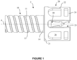
- An embodiment of the connector is represented in figure 1 .
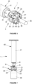
- the connector and the injection device connected to each other form an assembly, a first and a second embodiment of which are represented in figures 2 and 3 .
- the connector 2 is connected to an injection device 40 provided with a needle 47.
- the injection device is preferably a pre-filled syringe.
- the connector 2 is connected to an injection device 40 with no needle.
- the injection device is preferably a pre-filled syringe.
- a separate needle 70 is removably connected to the injection device 40 only after separating said injection device from the connector, as explained further.
- the connector 2 extends along a longitudinal axis A.
- the connector 2 comprises a proximal part 10 configured to be connected to the tip 42 of the injection device 40, a distal part 20 configured to be connected to a container 60, and a hollow spike 30 configured to pierce the septum 63 of the container when the distal part 20 is connected to the container.
- the container 60 is preferably a vial.
- the tip 42 of the injection device extends distally from the barrel 41 and is advantageously of a cylindrical or frustoconical shape.
- a sleeve 44 extends around and at a distance from the tip in the radial direction, thereby defining a housing 46 between the tip and the sleeve.
- the sleeve 44 comprises an inner surface provided with a threaded portion 45 that faces the outer surface 43 of the tip.
- Such a combination of the tip and the sleeve may be known as a Luer lock TM connection, although the invention is not limited to a connection sold under this designation.
- the barrel, tip and sleeve are made as a single part, by plastic injection molding.
- the barrel is made in glass, whereas the tip and sleeve are made in plastic.
- the proximal part 10 of the connector comprises a body 11 that encloses a hollow inner volume 12.
- the outer surface of the body is provided with a threaded portion 13 which is configured to be screwed to the corresponding threaded portion 45 of the inner surface of the sleeve 44.
- the inner surface of the body has a shape complementary to the outer surface of the tip to ensure a tight connection with the tip.
- the connector 2 is connected to the injection device 40 by inserting the body 11 of the connector in the housing 46 between the tip and the sleeve, by screwing the threaded portions 13, 45 of the body 11 and the sleeve 44.
- the tip 42 of the injection device is inserted in the inner volume 12 of the proximal part up to a distal region 14 of the proximal part.
- Figure 4 shows the alignment of the connector 2 and the injection device 40 along the axis A before connection, and a general side view of the resulting assembly 1 is represented in figure 5 .
- the screwing of the proximal part 10 of the connector to the sleeve 44 of the injection device ensures a tight and sealed connection between the connector 2 and the injection device 40, preventing any movement of the connector and the injection device relative to each other, and preventing any leakage from the assembly 1 to the outside of said assembly.
- the distal part 20 of the connector comprises a flange 21 which extends radially outwardly from the distal region 14 of the proximal part 10, and a skirt 22 which extends from the flange in the distal direction.
- the skirt 22 is adapted to be connected to the collar 62 of the container.
- the skirt has a substantially cylindrical shape that matches the shape of the collar.
- the skirt encloses the collar of the container.
- the skirt 22 may comprise at least one rim 25 that extends radially inwardly.
- Such rim 25 is configured to abut against a recess 64 of the collar 62 of the container 60 when the skirt 22 is connected to the container, thereby preventing the connector 2 from being pulled away in a proximal direction from the container 60.
- such rim prevents accidental removal of the connector during storage.
- the skirt 22 comprises a plurality of flexible tabs 24 separated from each other by recesses 23, said tabs being adapted to deflect radially outwardly for connecting the skirt to the container.
- the skirt thereby further fits to the dimensions of the collar, making the connection of the skirt to the container easier.
- the tabs 24 are provided at their distal end with borders 25 that extend radially inwardly.
- borders 25 that extend radially inwardly.
- the tabs 24 comprise hollow portions 26.
- the presence of the hollow portions facilitates the demolding of the connector during the manufacture, and further increase the ability of deflection of the tabs. In addition, the weight of the connector is reduced.
- the hollow spike 30 has a cylindrical shape delimited by an outer surface 37, and extends distally in the inner space 27 of the skirt 22 along the axis A from the flange 21.
- the distal end of the hollow spike 30 is provided with a pointed end 35 configured to perforate the pierceable septum 63 of the container when the connector 2 is connected to the container 60.
- the internal volume 32 of the spike is in fluidic communication with the inner volume 12 of the proximal part of the connector.
- the hollow spike 30 is completely covered by the skirt 22.
- the skirt acts as a rigid cover that reduces the risk of a user pricking himself or any person around.
- the skirt enables to auto-center the spike towards the pierceable septum 63 and thus eases the pricking of the pierceable septum 63 by the spike.
- the skirt protrudes 1 mm from the pointed end 35 of the hollow spike 30.
- the skirt 22 extends more distally than the spike 30.
- the spike 30 comprises a tapered pipe 33 that tapers away from said proximal part and a straight pipe 31 that extends further distally up to its pointed end 35.
- the spike 30 comprises an opening 34 close to the pointed end 35.
- the opening 34 creates a fluidic connection between the medical injection device 40 and the container 60 when connected thereto.
- the connector 2 is advantageously made in a single piece.
- the proximal part 10, the distal part 20, and the hollow spike 30 are formed in a single piece of material, such as a plastic material.
- An example of appropriate material is polypropylene.
- the assembly 1 further comprises a hollow sealing cap 50.
- a first embodiment of the sealing cap 50 is illustrated in figures 2 to 6
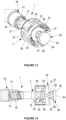
- a second embodiment is illustrated in figures 13 to 16 .
- the sealing cap comprises a closed distal part 52, a proximal part 53 provided with an opening 54, and a hollow body 51 that extends from the opening towards the distal part.
- the sealing cap is positioned on the spike 30 before connecting the connector 2 with the container 60, in particular during storage of the connector.
- the sealing cap 50 sealingly covers the spike 30, and in particular covers at least the opening 34 of said spike.
- the sealing cap 50 thus prevents any injury to a person at the vicinity of the assembly.
- the sealing cap is preferably made in a flexible material, such as elastomeric material, for example rubber or thermoplastic elastomer.
- the sealing cap 50 prevents any contamination of the spike from the external environment during storage.
- the hollow body 51 of the sealing cap has a shape that matches that of the spike so as to allow the insertion of the spike 30 in the hollow body of the sealing cap.
- the hollow body of the sealing cap has a cylindrical shape that tapers distally so as to match the pointed end of the spike.
- the proximal part 53 of the sealing cap is configured to be sealingly inserted into the flange 21 of the connector 2.
- the proximal end 55 of the sealing cap is inserted into a groove 16 provided in the flange 21 around the base 38 of the spike 30. This is clearly visible in figure 15 .
- the proximal end 55 of the sealing cap is griped in the groove 16 and radially abuts the flange 21 of the connector.
- the flange 21 may comprise a rim 15 that extends distally therefrom, around the base 38 of the spike.
- This abutment maintains the proximal part 53 of the sealing cap onto the spike 30, as well as ensuring an optimal sealing of said spike.
- This abutment is particularly useful when the sealing cap is made in a flexible material, wherein the proximal end 55 of the sealing cap is prone to extend radially outwardly due to the nature of the material.
- the sealing cap further preferably comprises a ring 58 that protrudes radially from and around the sealing cap 30.
- the ring 58 is preferably integral with the sealing cap.
- the ring 58 and the sealing cap are preferably made in the same material.
- the ring 58 is configured to abut the rim 25 of the skirt 22 when the sealing cap 50 is mounted on the hollow spike 30. This abutment prevents the sealing cap 30 from being pulled off during sterilization, handling, and/or transportation of the connector.
- the distal part 52 of the sealing cap 50 comprises a grip portion 80 configured to protrude distally away from the skirt when the sealing cap 50 is mounted on the hollow spike 30.
- the grip portion 80 is preferably integral with the sealing cap.
- the grip portion 80 and the sealing cap are preferably made in the same material.
- the grip portion 80 is configured to be handled by a user for mounting or removing the sealing cap 50 from the hollow spike 30.
- the grip portion 80 preferably comprises a stem 81 that extends in the distal direction, parallel to the longitudinal axis A, from the rest of the sealing cap.
- the stem 81 extends distally from the ring and protrudes sufficiently from the skirt to be gripped by the user without the fingers of the user contacting the skirt 22, thereby preventing contamination of the skirt by the user.
- the outer surface 82 of the stem may be advantageously be provided with grip marks that improve the grip of the fingers of the user onto said surface 82, thereby facilitating the positioning and the removal of the sealing cap.
- the grip portion 80 further comprises a flange 83 that is substantially perpendicular to the stem 81.
- the flange 83 acts as a handle the user may grip to manipulate the sealing cap easily.
- the thumb of the user may abut the distal surface 84 of the flange 83 and the index and middle finger of the user may abut the proximal surface 85 of the flange, which facilitates the removal of the sealing cap by helping him overcoming the resistance caused by the abutment of the ring 58 against the rim 25 of the skirt 22.
- the sealing cap 50 may be provided with an umbrella 86, preferably substantially circular, which extends radially outwardly from the stem 81 of the grip portion 80.
- the umbrella 86 comprises a proximal face 87 that faces the skirt 22, and a distal face 88 opposite the proximal face.
- the umbrella 86 is preferably configured to abut the skirt 22 when the sealing cap is pushed in the proximal direction toward the skirt.
- the diameter of the umbrella 86 is advantageously substantially equal to or greater than the diameter of the skirt 22 so as to cover said skirt when the connector is observed from the distal face 88 of the umbrella 86.
- the umbrella When removing the sealing cap 50 from the spike 30, the umbrella prevents the fingers of the user from contacting the skirt 22, thereby preventing contamination of said skirt by the user when removing the sealing cap 50.
- the sealing cap 50 may of course be mounted onto an injection device with no needle.
- a method for transferring a composition from the container sealed by a pierceable septum to the medical injection device will now be described in the following, in reference to the figures 4 to 12 .
- the connector 2 is connected to the injection device 40, by screwing the proximal part of the connector to the tip 42 of the injection device.
- the body 11 of the proximal part is inserted in the housing 46 and rotated to ensure screwing of the respective threaded portions 13, 45 of the connector and the injection device.
- the tip 42 of the injection device is inserted in the inner volume of the proximal part and the needle 47, when present, is enclosed in the spike 30.
- the assembly 1 obtained is represented in figure 5 .
- the spike 30 encloses a portion of the needle.
- the needle 47 extends along the axis A, from the tip 42 of the injection device, along the inner volume 32 of the spike, and further distally up to the distal end of the spike.
- the needle 47 may be staked in the tip 42.
- the injection outlet 49 of the needle preferably faces the opening 34 of the spike in an oblique or substantially radial direction.
- the connector 2 is then connected to the container 60.
- the distal part 20 of the connector engages the container 60, and the pointed end 35 of the spike perforates the septum 63 of the container.
- the skirt 22 of the connector is firmly attached to the collar 62 of the container and encloses said collar.
- the flange 21 of the distal part 20 abuts the collar 62 of the container, so that the spike 30 cannot go further distally inside the container.
- a portion 36 of the spike of a determined length including a portion 48 of the needle enclosed therein when present, is located in the container.
- the length of this portion 36 of spike depends on the length of the spike itself and the structure of the distal portion 20, and may be adjusted when the connector is being designed.
- the skirt 22 contacts the container, and the tabs 24 cover the collar 62.
- the tabs 24 may advantageously deflect radially outwardly to facilitate the connection.
- the borders 25 of the tabs abut against the recess 64 of the collar, thereby preventing the connector 2 from being separated from the container.
- the container 60 is thus maintained in a fixed position to the connector 2.
- the spike 30 extends along the axis A in the inner space 27 of the skirt and said skirt encloses the collar of the container, the spike 30 is centered relative to the top surface 65 of the septum 63 of the container. This allows the insertion of the spike, and the needle enclosed herein when present, at the center of said top surface 65 of the septum, the spike 30 piercing the center portion 66 of the septum typically made of elastomer that is not covered by aluminum. Since the needle 47 is protected by the spike 30, it does not contact the septum or the wall of the container, and any deformation of the needle 47 is thus prevented.
- the skirt 22 When the skirt 22 extends more distally than the spike 30, the skirt 22 begins engaging the collar 62 of the container as the spike is proximally remote from the septum. Hence, thanks to the skirt, the spike is centered relative to the top surface 65 of the septum 63 and guided to the center portion 66 of the septum until full engagement of the connector onto the container.
- the connector 2 is configured so that when the spike 30 is inserted in the septum 63 of the container, the opening 34 of the spike is located slightly distally relative to the septum, in the vicinity of the septum.
- a first composition, contained in the injection device, is then transferred into the container prefilled with a second composition.
- the user pushes the plunger rod (not represented) of the injection device in the distal direction.
- the composition flows along the needle 47, passes through the outlet 49 of the needle, and is expelled from the spike 30 via the opening 34 and transferred into the container 60.
- the first composition passes directly from the outlet of the needle to the opening of the spike, which limits the contact of said first composition with the inner volume of the spike and limits pressure losses.
- the composition flows along the spike 30 in contact with the inner wall of the spike, and is expelled from the spike via the opening 34 and transferred into the container 60.
- the first composition is then mixed with the second composition.
- the user may handle both the assembly 1 and the container 60, and shake them gently so as to allow the mixing.
- the mixed compositions are then drawn back to the injection device.
- the assembly 1 and the container 60 are turned upside down, and the user pulls the plunger rod of the injection device, thereby creating a suction effect through the spike.
- the opening 34 of the spike remains immersed in the mixed compositions regardless the amount of compositions remaining in the container. Therefore, complete withdrawal can be achieved with no need to adjust the length of the portion 36 of the spike inserted in the container.
- the user does not need to move the needle relative to the container as in the prior art for keeping the needle immersed in the mixed compositions as long as the withdrawal goes. This saves the user from having to perform complicated and imprecise manipulations in order to adjust the length of the portion of needle inserted in the container, and makes the transfer between the injection device and the container much faster and easier.
- the suction effect is also created in the needle 47.
- the mixed compositions flow from the container 60 into the needle 47 via the opening 34 of the spike and the outlet 49 of the needle, and is then transferred into the barrel 61 of the injection device.
- the mixed compositions pass directly from the opening 34 of the spike to the outlet 49 of the needle, which limits the contact of said composition with the inner wall of the spike and limits pressure losses.
- the mixed compositions flow from the container 60 into the inner volume 32 of the spike via the opening 34 of the spike, and is then transferred into the barrel 61 of the injection device.
- connection between the proximal part of the connector and the tip and sleeve of the injection device ensures the sealing of the assembly and prevents any leak from the assembly to the outside of said assembly.
- the injection device 40 is then separated from the connector 2.
- the body 11 of the proximal part is rotated to cause unscrewing of the respective threaded portions 13, 45 of the connector and the injection device.
- the tip 42 of the injection device disengages the inner volume of the proximal part, and the needle 47, when present, is removed from the spike 30.
- the connector 2 remains connected to the container 60 and may be further disposed of.
- the injection device containing the mixed compositions is then ready to be used.
- a needle 70 is removably mounted on the tip 42 of the injection device after separating the injection device from the container, as illustrated in figures 11 and 12 .
- the needle 70 is fixed to the injection device via its fitting 71 which is inserted in the housing 46 between the tip 42 and the sleeve 44 of the injection device, preferably by screwing onto the sleeve.
- the method described above is related to the reconstitution of a drug, wherein the first composition is a diluent and the second composition is a drug content, such as for example a lyophilized drug or an active substance of a drug.
Landscapes
- Health & Medical Sciences (AREA)
- Pharmacology & Pharmacy (AREA)
- Life Sciences & Earth Sciences (AREA)
- Animal Behavior & Ethology (AREA)
- General Health & Medical Sciences (AREA)
- Public Health (AREA)
- Veterinary Medicine (AREA)
- Physics & Mathematics (AREA)
- Fluid Mechanics (AREA)
- Infusion, Injection, And Reservoir Apparatuses (AREA)
Claims (19)
- Verbinder (2) zum Verbinden einer medizinischen Injektionsvorrichtung (40), die eine distale Spitze (42) und eine Hülse (44) aufweist, die sich um die Spitze herum erstreckt, wobei die Hülse (44) mit einem Abschnitt (45) mit Innengewinde versehen ist, mit einem Behälter (60), der durch eine durchstechbare Scheidewand (63) geschlossen ist, wobei der Verbinder (2) umfasst:- einen proximalen Teil (10), der dazu ausgestaltet ist, dichtend mit der Spitze (42) der Injektionsvorrichtung (40) ineinanderzugreifen, wobei der proximale Teil (10) einen Abschnitt (13) mit Außengewinde umfasst, der dazu ausgestaltet ist, abnehmbar an den Abschnitt (45) mit Innengewinde der Hülse geschraubt zu werden,- einen distalen Teil (20), der dazu ausgestaltet ist, mit dem Behälter (60) verbunden zu werden,- einen hohlen Dorn (30), der sich distal von dem proximalen Teil (10) erstreckt und ein Innenvolumen (32) aufweist, das dazu ausgestaltet ist, mit der Injektionsvorrichtung (40) in Fluidverbindung zu stehen, wobei der Dorn (30) dazu ausgestaltet ist, die durchstechbare Scheidewand (63) des Behälters (60) zu perforieren, wenn der distale Teil (20) mit dem Behälter verbunden wird, wobei der Dorn (30) eine Öffnung (34) in einem distalen Ende umfasst, wobei die Öffnung (34) dazu ausgestaltet ist, eine Fluidverbindung zwischen der medizinischen Injektionsvorrichtung (40) und dem Behälter (60) zu schaffen, und- eine Dichtungskappe (50), die derart an dem hohlen Dorn (30) montiert ist, dass mindestens die Öffnung (34) des hohlen Dorns (30) dichtend umschlossen wird,wobei der distale Teil (20) eine Schürze (22) umfasst, die sich um den hohlen Dorn (30) herum erstreckt, wobei die Schürze (22) angepasst ist, um mindestens den Hals (62) des Behälters (60) zu umschließen, wenn sie mit dem Behälter verbunden ist,wobei die Schürze (22) einen Flansch (21) umfasst, die Dichtungskappe (50) einen geschlossenen distalen Teil (52), einen proximalen Teil (53), der mit einer Öffnung (54) versehen ist, und einen hohlen Körper (51) umfasst, der sich von der Öffnung hin zum distalen Teil erstreckt, wobei der hohle Körper (51) dazu ausgestaltet ist, mit dem hohlen Dorn (30) dichtend ineinanderzugreifen, dadurch gekennzeichnet, dassder proximale Teil (53) der Dichtungskappe dazu ausgestaltet ist, dichtend und zumindest teilweise in eine Nut (16) eingesetzt zu sein, die in dem Flansch (21) bereitgestellt ist, derart dass der proximale Teil (53) der Dichtungskappe radial an eine innere Oberfläche der Nut (16) anstößt.
- Verbinder nach Anspruch 1, wobei die Schürze (22) mindestens eine Einfassung (25) umfasst, die sich radial nach innen erstreckt, wobei die Einfassung (25) dazu ausgestaltet ist, mit einer Aussparung (64) des Halses (62) des Behälters (60) ineinanderzugreifen, wenn die Schürze (22) mit dem Behälter (60) verbunden ist.
- Verbinder nach Anspruch 1, wobei die Schürze (22) angepasst ist, sich radial nach außen zu biegen, wenn sie mit dem Behälter (60) verbunden wird.
- Verbinder nach Anspruch 1, wobei die Schürze (22) mit einer Vielzahl von biegsamen Laschen (24) versehen ist, die durch Aussparungen (23) voneinander getrennt sind, wobei die biegsamen Laschen (24) dazu ausgestaltet sind, sich radial nach außen zu biegen, wenn die Schürze (22) mit dem Behälter (60) verbunden wird.
- Verbinder nach einem der vorhergehenden Ansprüche, wobei die Schürze (22) sich distaler erstreckt als der Dorn (30).
- Verbinder nach einem der vorhergehenden Ansprüche, wobei das Innenvolumen (32) des hohlen Dorns (30) dazu ausgestaltet ist, eine Nadel (47) der Injektionsvorrichtung (40) aufzunehmen, die an der Spitze (42) der Injektionsvorrichtung befestigt ist.
- Verbinder nach einem der vorhergehenden Ansprüche, wobei die Dichtungskappe ferner einen Ring (58) umfasst, der von dem hohlen Körper (51) radial nach außen hervorsteht, wobei der Ring (58) dazu ausgestaltet ist, an die Schürze (22) anzustoßen, wenn die Dichtungskappe (50) an dem hohlen Dorn (30) montiert ist, derart dass die Dichtungskappe (50) an dem hohlen Dorn (30) zurückgehalten wird.
- Verbinder nach Anspruch 10 in Kombination mit Anspruch 2, wobei der Ring (58) dazu ausgestaltet ist, an die Einfassung (25) der Schürze (22) anzustoßen, wenn die Dichtungskappe (50) an dem hohlen Dorn (30) montiert ist.
- Verbinder nach einem von Anspruch 7 oder Anspruch 8, wobei der Ring (58) einteilig mit der Dichtungskappe (50) ist.
- Verbinder nach einem der vorhergehenden Ansprüche, wobei der distale Teil (52) der Dichtungskappe (50) einen Greifabschnitt (80) umfasst, der dazu ausgestaltet ist, von der Schürze (22) weg distal hervorzustehen, wenn die Dichtungskappe (50) an dem hohlen Dorn (30) montiert ist, und dazu ausgestaltet ist, durch einen Benutzer zum Montieren oder Entfernen der Dichtungskappe (50) an bzw. von dem hohlen Dorn (30) gehandhabt zu werden.
- Verbinder nach Anspruch 10, wobei der Greifabschnitt (80) einen Stamm (81), der von der Schürze (22) hervorsteht, und einen Flansch (83) umfasst, der im Wesentlichen senkrecht zu dem Stamm (81) ist und als ein Griff wirkt, der dazu ausgestaltet ist, zwischen den Fingern eines Benutzers gegriffen zu werden, um die Dichtungskappe zu manipulieren.
- Anordnung (1), die umfasst:- eine medizinische Injektionsvorrichtung (40), die einen Zylinder (41), eine Spitze (42), die sich distal von dem Zylinder erstreckt, und eine Hülse (44) umfasst, die sich um die Spitze herum erstreckt, wobei die Hülse (44) mit einem Abschnitt mit Innengewinde versehen ist, und- einen Verbinder (2) nach einem der vorhergehenden Ansprüche,wobei der proximale Teil (10) des Verbinders (2) sich in Gewindeeingriff mit dem Gewindeabschnitt (45) der Hülse (44) befindet und dichtend mit der Spitze (42) der medizinischen Injektionsvorrichtung (40) ineinandergreift.
- Anordnung nach Anspruch 12, wobei die medizinische Injektionsvorrichtung (40) eine Nadel (47) umfasst, die in der Spitze (42) eingesetzt ist, wobei die Nadel sich in den hohlen Dorn (30) des Verbinders (2) erstreckt.
- Anordnung nach Anspruch 13, wobei die Nadel (47) sich bis zur Öffnung (34) des Dorns in den hohlen Dorn (30) erstreckt.
- Anordnung nach Anspruch 14, wobei ein Injektionsauslass (49) der Nadel (47) und die Öffnung (34) des Dorns (30) einander in einer radialen Richtung zugewandt sind.
- Anordnung nach einem der Ansprüche 12 bis 14, wobei der Zylinder, die Spitze und die Hülse einteilig als ein einziges Stück gebildet sind.
- Anordnung nach einem der Ansprüche 12 bis 16, wobei die medizinische Injektionsvorrichtung (40) eine vorgefüllte Spritze ist, und wobei der Verbinder ein Verbinder nach einem der Ansprüche 1 bis 11 ist, wobei die Dichtungskappe auf den hohlen Dorn (30) montiert ist.
- Verfahren zum Übertragen einer Zusammensetzung von einem Behälter (60), der durch eine durchstechbare Scheidewand (63) abgedichtet ist, zu einer medizinischen Injektionsvorrichtung (40), wobei das Verfahren die folgenden Schritte umfasst:- Bereitstellen einer vorgefüllten medizinischen Injektionsvorrichtung (40) mit einer Spitze (42) und einer Hülse (44), die sich um die Spitze herum erstreckt, wobei die Hülse (44) mit einem Gewindeabschnitt (45) versehen ist, und eines Verbinders (2) nach einem der Ansprüche 1 bis 11, der über den Gewindeabschnitt (45) der Hülse (44) an die Spitze (42) geschraubt wird,- Verbinden des Verbinders (2) mit dem Behälter (60) durch Ineingriffbringen des distalen Teils (20) des Verbinders mit dem Behälter, wobei der hohle Dorn (30) dadurch die Scheidewand (63) des Behälters (60) perforiert,- Übertragen einer ersten Zusammensetzung, die in der Injektionsvorrichtung (40) enthalten ist, durch das Innenvolumen (32) des Dorns (30) in den Behälter (60),- Mischen der ersten Zusammensetzung mit einer zweiten Zusammensetzung, die in dem Behälter (60) enthalten ist,- Ziehen der gemischten Zusammensetzungen von dem Behälter (60) zurück zur Injektionsvorrichtung (40),- Abschrauben der Injektionsvorrichtung (40) von dem Verbinder (2).
- Verfahren nach Anspruch 18, wobei vor dem Verbinden des Verbinders (2) mit dem Behälter (60) die Dichtungskappe (50) von dem Dorn (30) entfernt wird, um den Dorn (30) und die Öffnung (34) freizulegen.
Applications Claiming Priority (2)
| Application Number | Priority Date | Filing Date | Title |
|---|---|---|---|
| EP18305609 | 2018-05-17 | ||
| PCT/EP2019/061102 WO2019219383A1 (en) | 2018-05-17 | 2019-04-30 | Connector for connecting a medical injection device to a container |
Publications (3)
| Publication Number | Publication Date |
|---|---|
| EP3793504A1 EP3793504A1 (de) | 2021-03-24 |
| EP3793504B1 true EP3793504B1 (de) | 2024-03-13 |
| EP3793504C0 EP3793504C0 (de) | 2024-03-13 |
Family
ID=62386317
Family Applications (1)
| Application Number | Title | Priority Date | Filing Date |
|---|---|---|---|
| EP19722051.0A Active EP3793504B1 (de) | 2018-05-17 | 2019-04-30 | Verbinder zum verbinden einer medizinischen injektionsvorrichtung mit einem behälter |
Country Status (6)
| Country | Link |
|---|---|
| US (1) | US11992463B2 (de) |
| EP (1) | EP3793504B1 (de) |
| JP (1) | JP7270646B2 (de) |
| CN (1) | CN112105328B (de) |
| ES (1) | ES2974449T3 (de) |
| WO (1) | WO2019219383A1 (de) |
Families Citing this family (6)
| Publication number | Priority date | Publication date | Assignee | Title |
|---|---|---|---|---|
| CN113208916B (zh) | 2020-01-21 | 2024-12-13 | 贝克顿·迪金森公司 | 药瓶适配器装置 |
| CN114939062A (zh) | 2021-02-14 | 2022-08-26 | 贝克顿·迪金森公司 | 鼻喷雾剂重配系统 |
| EP4049708B1 (de) | 2021-02-26 | 2026-01-21 | Becton Dickinson Holdings Pte. Ltd. | Konnektoranordnung und verfahren zur herstellung derselben |
| ES2995474T3 (en) | 2022-01-18 | 2025-02-10 | Becton Dickinson France | Vial adaptor providing audible feedback and connector assembly for medical injection device including vial adaptor |
| ES3015511T3 (en) | 2022-01-18 | 2025-05-06 | Becton Dickinson France | Connector assembly for medical injection device |
| AU2024214954A1 (en) * | 2023-02-01 | 2025-07-24 | Equashield Medical Ltd | Adaptor for use in a fluid transfer system |
Citations (1)
| Publication number | Priority date | Publication date | Assignee | Title |
|---|---|---|---|---|
| US20100179506A1 (en) * | 2009-01-15 | 2010-07-15 | Eli Shemesh | Vial adapter element |
Family Cites Families (21)
| Publication number | Priority date | Publication date | Assignee | Title |
|---|---|---|---|---|
| EP0692235A1 (de) * | 1994-07-14 | 1996-01-17 | International Medication Systems (U.K.) Ltd. | Vorrichtung zum Mengen und Abgeben |
| US5893397A (en) * | 1996-01-12 | 1999-04-13 | Bioject Inc. | Medication vial/syringe liquid-transfer apparatus |
| JP4277241B2 (ja) * | 1998-12-24 | 2009-06-10 | Smc株式会社 | 流体圧機器の管体接続構造 |
| US6875205B2 (en) * | 2002-02-08 | 2005-04-05 | Alaris Medical Systems, Inc. | Vial adapter having a needle-free valve for use with vial closures of different sizes |
| US8454573B2 (en) * | 2008-05-06 | 2013-06-04 | Philip Wyatt | Medicament administration apparatus |
| DK1919432T3 (da) * | 2005-08-11 | 2012-01-30 | Medimop Medical Projects Ltd | Overføringsindretninger for flydende medikamenter til fejlsikker korrekt rasteforbindelse på medicinske ampuller |
| US20120199096A1 (en) * | 2009-10-13 | 2012-08-09 | Honda Motor Co., Ltd. | Cover member fastening method and fastening structure for a head cover |
| EP2347750A1 (de) * | 2010-01-26 | 2011-07-27 | Fresenius Kabi Deutschland GmbH | Konnektor für medizinischen Wirkstoff enthaltende Behälter |
| US8721612B2 (en) * | 2010-12-17 | 2014-05-13 | Hospira, Inc. | System and method for intermixing the contents of two containers |
| FR2975896B1 (fr) | 2011-06-06 | 2014-06-06 | Biocorp Rech Et Dev | Dispositif de connexion entre un recipient et un contenant, procede d'assemblage et d'utilisation d'un tel dispositif |
| SG192312A1 (en) * | 2012-02-02 | 2013-08-30 | Becton Dickinson Holdings Pte Ltd | Adaptor for coupling to a medical container |
| US9144646B2 (en) * | 2012-04-25 | 2015-09-29 | Fresenius Medical Care Holdings, Inc. | Vial spiking devices and related assemblies and methods |
| CN202886861U (zh) * | 2012-09-03 | 2013-04-17 | 深圳市宝亚莱科技有限公司 | 防水手表 |
| TWI580451B (zh) * | 2013-03-15 | 2017-05-01 | 安美基公司 | 用於注射器之匣盒及使用具有自動注射器及匣盒之自動注射器設備之方法 |
| BR112015027555B1 (pt) | 2013-05-10 | 2022-02-01 | Medimop Medical Projects Ltd | Dispositivo médico para uso com uma seringa sem agulha, um frasco e um veículo líquido para preencher a seringa sem agulha com uma solução de injeção para injeção em um paciente |
| EP2826519A1 (de) * | 2013-07-15 | 2015-01-21 | Becton Dickinson France | Adapter für Arzneimittelabgabevorrichtung und Verfahren zur Montage des besagten Adapters daran |
| US9925343B2 (en) * | 2013-08-07 | 2018-03-27 | Unitract Syringe Pty Ltd | Luer connection adapters for syringes |
| EP3034118B1 (de) | 2013-08-14 | 2019-09-18 | Terumo Kabushiki Kaisha | Spritze |
| US10813837B2 (en) * | 2014-03-05 | 2020-10-27 | Yukon Medical, Llc | Pre-filled diluent syringe vial adapter |
| US10137237B2 (en) * | 2014-04-03 | 2018-11-27 | Novo Nordisk A/S | Needle arrangement |
| EP3747421B1 (de) * | 2019-06-06 | 2026-02-18 | Fresenius Kabi Deutschland GmbH | Als infusionsbeutel ausgebildete medizinische verpackung |
-
2019
- 2019-04-30 EP EP19722051.0A patent/EP3793504B1/de active Active
- 2019-04-30 WO PCT/EP2019/061102 patent/WO2019219383A1/en not_active Ceased
- 2019-04-30 JP JP2020562196A patent/JP7270646B2/ja active Active
- 2019-04-30 US US17/055,674 patent/US11992463B2/en active Active
- 2019-04-30 ES ES19722051T patent/ES2974449T3/es active Active
- 2019-04-30 CN CN201980031378.9A patent/CN112105328B/zh active Active
Patent Citations (1)
| Publication number | Priority date | Publication date | Assignee | Title |
|---|---|---|---|---|
| US20100179506A1 (en) * | 2009-01-15 | 2010-07-15 | Eli Shemesh | Vial adapter element |
Also Published As
| Publication number | Publication date |
|---|---|
| US20210186814A1 (en) | 2021-06-24 |
| US11992463B2 (en) | 2024-05-28 |
| EP3793504C0 (de) | 2024-03-13 |
| JP2021522909A (ja) | 2021-09-02 |
| CN112105328B (zh) | 2024-03-01 |
| ES2974449T3 (es) | 2024-06-27 |
| WO2019219383A1 (en) | 2019-11-21 |
| EP3793504A1 (de) | 2021-03-24 |
| JP7270646B2 (ja) | 2023-05-10 |
| CN112105328A (zh) | 2020-12-18 |
Similar Documents
| Publication | Publication Date | Title |
|---|---|---|
| US11992463B2 (en) | Connector for connecting a medical injection device to a container | |
| EP0637443B1 (de) | Einrichtung zur Ermöglichung des Zugriffs auf Medikamente in Ampullen | |
| JP2988661B2 (ja) | バイアル及びアンプルからの流体にアクセスする流体移送装置及びその装置を使用して流体を移送する方法 | |
| EP0888794B1 (de) | Verfahren zum Befüllen von Spritzen | |
| US4969883A (en) | Medicament vial end cap membrane piercing device | |
| US20180369491A1 (en) | Medical delivery device | |
| JP2013514113A (ja) | 注射器 | |
| US11357929B2 (en) | Needle storage magazine assembly | |
| EP0820779B1 (de) | Vorrichtung zum Befüllen und zum Verabreichen des Inhalts von Spritzen | |
| US20170014579A1 (en) | Blunt cannula needle device | |
| US12551630B2 (en) | Connector for connecting a medical injection device to a container and assembly comprising said connector and medical injection device | |
| WO2017189909A1 (en) | Needle storage magazine assembly | |
| US3890972A (en) | Syringe injector with pop-top cap | |
| KR102181488B1 (ko) | 의료용 주입기용 t자 형상의 캡 | |
| EP4190304B1 (de) | Verfahren zum befüllen einer medizinischen injektionsvorrichtung mit einer zusammensetzung | |
| JP3294537B2 (ja) | バイアル及びアンプルからの流体にアクセスする流体移送装置及びその装置を使用して流体を移送する方法 | |
| CA2022166A1 (en) | Medicament vial end cap membrane piercing device |
Legal Events
| Date | Code | Title | Description |
|---|---|---|---|
| STAA | Information on the status of an ep patent application or granted ep patent |
Free format text: STATUS: UNKNOWN |
|
| STAA | Information on the status of an ep patent application or granted ep patent |
Free format text: STATUS: THE INTERNATIONAL PUBLICATION HAS BEEN MADE |
|
| PUAI | Public reference made under article 153(3) epc to a published international application that has entered the european phase |
Free format text: ORIGINAL CODE: 0009012 |
|
| STAA | Information on the status of an ep patent application or granted ep patent |
Free format text: STATUS: REQUEST FOR EXAMINATION WAS MADE |
|
| 17P | Request for examination filed |
Effective date: 20201203 |
|
| AK | Designated contracting states |
Kind code of ref document: A1 Designated state(s): AL AT BE BG CH CY CZ DE DK EE ES FI FR GB GR HR HU IE IS IT LI LT LU LV MC MK MT NL NO PL PT RO RS SE SI SK SM TR |
|
| AX | Request for extension of the european patent |
Extension state: BA ME |
|
| RIN1 | Information on inventor provided before grant (corrected) |
Inventor name: YAN, BO Inventor name: HAMEL, JEAN-BERNARD Inventor name: HUANG, LONGXIANG |
|
| DAV | Request for validation of the european patent (deleted) | ||
| DAX | Request for extension of the european patent (deleted) | ||
| GRAP | Despatch of communication of intention to grant a patent |
Free format text: ORIGINAL CODE: EPIDOSNIGR1 |
|
| STAA | Information on the status of an ep patent application or granted ep patent |
Free format text: STATUS: GRANT OF PATENT IS INTENDED |
|
| INTG | Intention to grant announced |
Effective date: 20231027 |
|
| GRAS | Grant fee paid |
Free format text: ORIGINAL CODE: EPIDOSNIGR3 |
|
| GRAA | (expected) grant |
Free format text: ORIGINAL CODE: 0009210 |
|
| STAA | Information on the status of an ep patent application or granted ep patent |
Free format text: STATUS: THE PATENT HAS BEEN GRANTED |
|
| AK | Designated contracting states |
Kind code of ref document: B1 Designated state(s): AL AT BE BG CH CY CZ DE DK EE ES FI FR GB GR HR HU IE IS IT LI LT LU LV MC MK MT NL NO PL PT RO RS SE SI SK SM TR |
|
| REG | Reference to a national code |
Ref country code: GB Ref legal event code: FG4D |
|
| REG | Reference to a national code |
Ref country code: CH Ref legal event code: EP |
|
| REG | Reference to a national code |
Ref country code: DE Ref legal event code: R096 Ref document number: 602019048186 Country of ref document: DE |
|
| REG | Reference to a national code |
Ref country code: IE Ref legal event code: FG4D |
|
| U01 | Request for unitary effect filed |
Effective date: 20240409 |
|
| U07 | Unitary effect registered |
Designated state(s): AT BE BG DE DK EE FI FR IT LT LU LV MT NL PT SE SI Effective date: 20240416 |
|
| U20 | Renewal fee for the european patent with unitary effect paid |
Year of fee payment: 6 Effective date: 20240426 |
|
| REG | Reference to a national code |
Ref country code: ES Ref legal event code: FG2A Ref document number: 2974449 Country of ref document: ES Kind code of ref document: T3 Effective date: 20240627 |
|
| PG25 | Lapsed in a contracting state [announced via postgrant information from national office to epo] |
Ref country code: GR Free format text: LAPSE BECAUSE OF FAILURE TO SUBMIT A TRANSLATION OF THE DESCRIPTION OR TO PAY THE FEE WITHIN THE PRESCRIBED TIME-LIMIT Effective date: 20240614 |
|
| PG25 | Lapsed in a contracting state [announced via postgrant information from national office to epo] |
Ref country code: HR Free format text: LAPSE BECAUSE OF FAILURE TO SUBMIT A TRANSLATION OF THE DESCRIPTION OR TO PAY THE FEE WITHIN THE PRESCRIBED TIME-LIMIT Effective date: 20240313 Ref country code: RS Free format text: LAPSE BECAUSE OF FAILURE TO SUBMIT A TRANSLATION OF THE DESCRIPTION OR TO PAY THE FEE WITHIN THE PRESCRIBED TIME-LIMIT Effective date: 20240613 |
|
| PG25 | Lapsed in a contracting state [announced via postgrant information from national office to epo] |
Ref country code: RS Free format text: LAPSE BECAUSE OF FAILURE TO SUBMIT A TRANSLATION OF THE DESCRIPTION OR TO PAY THE FEE WITHIN THE PRESCRIBED TIME-LIMIT Effective date: 20240613 Ref country code: NO Free format text: LAPSE BECAUSE OF FAILURE TO SUBMIT A TRANSLATION OF THE DESCRIPTION OR TO PAY THE FEE WITHIN THE PRESCRIBED TIME-LIMIT Effective date: 20240613 Ref country code: HR Free format text: LAPSE BECAUSE OF FAILURE TO SUBMIT A TRANSLATION OF THE DESCRIPTION OR TO PAY THE FEE WITHIN THE PRESCRIBED TIME-LIMIT Effective date: 20240313 Ref country code: GR Free format text: LAPSE BECAUSE OF FAILURE TO SUBMIT A TRANSLATION OF THE DESCRIPTION OR TO PAY THE FEE WITHIN THE PRESCRIBED TIME-LIMIT Effective date: 20240614 |
|
| PG25 | Lapsed in a contracting state [announced via postgrant information from national office to epo] |
Ref country code: IS Free format text: LAPSE BECAUSE OF FAILURE TO SUBMIT A TRANSLATION OF THE DESCRIPTION OR TO PAY THE FEE WITHIN THE PRESCRIBED TIME-LIMIT Effective date: 20240713 |
|
| PG25 | Lapsed in a contracting state [announced via postgrant information from national office to epo] |
Ref country code: SM Free format text: LAPSE BECAUSE OF FAILURE TO SUBMIT A TRANSLATION OF THE DESCRIPTION OR TO PAY THE FEE WITHIN THE PRESCRIBED TIME-LIMIT Effective date: 20240313 |
|
| PG25 | Lapsed in a contracting state [announced via postgrant information from national office to epo] |
Ref country code: CZ Free format text: LAPSE BECAUSE OF FAILURE TO SUBMIT A TRANSLATION OF THE DESCRIPTION OR TO PAY THE FEE WITHIN THE PRESCRIBED TIME-LIMIT Effective date: 20240313 |
|
| PG25 | Lapsed in a contracting state [announced via postgrant information from national office to epo] |
Ref country code: PL Free format text: LAPSE BECAUSE OF FAILURE TO SUBMIT A TRANSLATION OF THE DESCRIPTION OR TO PAY THE FEE WITHIN THE PRESCRIBED TIME-LIMIT Effective date: 20240313 |
|
| PG25 | Lapsed in a contracting state [announced via postgrant information from national office to epo] |
Ref country code: SK Free format text: LAPSE BECAUSE OF FAILURE TO SUBMIT A TRANSLATION OF THE DESCRIPTION OR TO PAY THE FEE WITHIN THE PRESCRIBED TIME-LIMIT Effective date: 20240313 |
|
| PG25 | Lapsed in a contracting state [announced via postgrant information from national office to epo] |
Ref country code: SM Free format text: LAPSE BECAUSE OF FAILURE TO SUBMIT A TRANSLATION OF THE DESCRIPTION OR TO PAY THE FEE WITHIN THE PRESCRIBED TIME-LIMIT Effective date: 20240313 Ref country code: SK Free format text: LAPSE BECAUSE OF FAILURE TO SUBMIT A TRANSLATION OF THE DESCRIPTION OR TO PAY THE FEE WITHIN THE PRESCRIBED TIME-LIMIT Effective date: 20240313 Ref country code: RO Free format text: LAPSE BECAUSE OF FAILURE TO SUBMIT A TRANSLATION OF THE DESCRIPTION OR TO PAY THE FEE WITHIN THE PRESCRIBED TIME-LIMIT Effective date: 20240313 Ref country code: PL Free format text: LAPSE BECAUSE OF FAILURE TO SUBMIT A TRANSLATION OF THE DESCRIPTION OR TO PAY THE FEE WITHIN THE PRESCRIBED TIME-LIMIT Effective date: 20240313 Ref country code: IS Free format text: LAPSE BECAUSE OF FAILURE TO SUBMIT A TRANSLATION OF THE DESCRIPTION OR TO PAY THE FEE WITHIN THE PRESCRIBED TIME-LIMIT Effective date: 20240713 Ref country code: CZ Free format text: LAPSE BECAUSE OF FAILURE TO SUBMIT A TRANSLATION OF THE DESCRIPTION OR TO PAY THE FEE WITHIN THE PRESCRIBED TIME-LIMIT Effective date: 20240313 |
|
| REG | Reference to a national code |
Ref country code: DE Ref legal event code: R097 Ref document number: 602019048186 Country of ref document: DE |
|
| PG25 | Lapsed in a contracting state [announced via postgrant information from national office to epo] |
Ref country code: MC Free format text: LAPSE BECAUSE OF FAILURE TO SUBMIT A TRANSLATION OF THE DESCRIPTION OR TO PAY THE FEE WITHIN THE PRESCRIBED TIME-LIMIT Effective date: 20240313 |
|
| PLBE | No opposition filed within time limit |
Free format text: ORIGINAL CODE: 0009261 |
|
| STAA | Information on the status of an ep patent application or granted ep patent |
Free format text: STATUS: NO OPPOSITION FILED WITHIN TIME LIMIT |
|
| PG25 | Lapsed in a contracting state [announced via postgrant information from national office to epo] |
Ref country code: MC Free format text: LAPSE BECAUSE OF FAILURE TO SUBMIT A TRANSLATION OF THE DESCRIPTION OR TO PAY THE FEE WITHIN THE PRESCRIBED TIME-LIMIT Effective date: 20240313 |
|
| 26N | No opposition filed |
Effective date: 20241216 |
|
| PG25 | Lapsed in a contracting state [announced via postgrant information from national office to epo] |
Ref country code: IE Free format text: LAPSE BECAUSE OF NON-PAYMENT OF DUE FEES Effective date: 20240430 |
|
| U20 | Renewal fee for the european patent with unitary effect paid |
Year of fee payment: 7 Effective date: 20250319 |
|
| PGFP | Annual fee paid to national office [announced via postgrant information from national office to epo] |
Ref country code: ES Payment date: 20250502 Year of fee payment: 7 |
|
| PGFP | Annual fee paid to national office [announced via postgrant information from national office to epo] |
Ref country code: CH Payment date: 20250501 Year of fee payment: 7 |
|
| PG25 | Lapsed in a contracting state [announced via postgrant information from national office to epo] |
Ref country code: CY Free format text: LAPSE BECAUSE OF FAILURE TO SUBMIT A TRANSLATION OF THE DESCRIPTION OR TO PAY THE FEE WITHIN THE PRESCRIBED TIME-LIMIT; INVALID AB INITIO Effective date: 20190430 |
|
| PG25 | Lapsed in a contracting state [announced via postgrant information from national office to epo] |
Ref country code: HU Free format text: LAPSE BECAUSE OF FAILURE TO SUBMIT A TRANSLATION OF THE DESCRIPTION OR TO PAY THE FEE WITHIN THE PRESCRIBED TIME-LIMIT; INVALID AB INITIO Effective date: 20190430 |
|
| PGFP | Annual fee paid to national office [announced via postgrant information from national office to epo] |
Ref country code: GB Payment date: 20260319 Year of fee payment: 8 |
|
| U20 | Renewal fee for the european patent with unitary effect paid |
Year of fee payment: 8 Effective date: 20260319 |
|
| REG | Reference to a national code |
Ref country code: CH Ref legal event code: U11 Free format text: ST27 STATUS EVENT CODE: U-0-0-U10-U11 (AS PROVIDED BY THE NATIONAL OFFICE) Effective date: 20260501 |