EP3793832B1 - System und verfahren zum betrieb eines industriellen druckers - Google Patents
System und verfahren zum betrieb eines industriellen druckers Download PDFInfo
- Publication number
- EP3793832B1 EP3793832B1 EP19803719.4A EP19803719A EP3793832B1 EP 3793832 B1 EP3793832 B1 EP 3793832B1 EP 19803719 A EP19803719 A EP 19803719A EP 3793832 B1 EP3793832 B1 EP 3793832B1
- Authority
- EP
- European Patent Office
- Prior art keywords
- ink
- printer
- coo
- consumption
- solvent
- Prior art date
- Legal status (The legal status is an assumption and is not a legal conclusion. Google has not performed a legal analysis and makes no representation as to the accuracy of the status listed.)
- Active
Links
Images







Classifications
-
- G—PHYSICS
- G06—COMPUTING OR CALCULATING; COUNTING
- G06F—ELECTRIC DIGITAL DATA PROCESSING
- G06F3/00—Input arrangements for transferring data to be processed into a form capable of being handled by the computer; Output arrangements for transferring data from processing unit to output unit, e.g. interface arrangements
- G06F3/12—Digital output to print unit, e.g. line printer, chain printer
- G06F3/1201—Dedicated interfaces to print systems
- G06F3/1202—Dedicated interfaces to print systems specifically adapted to achieve a particular effect
- G06F3/1203—Improving or facilitating administration, e.g. print management
- G06F3/1204—Improving or facilitating administration, e.g. print management resulting in reduced user or operator actions, e.g. presetting, automatic actions, using hardware token storing data
-
- B—PERFORMING OPERATIONS; TRANSPORTING
- B41—PRINTING; LINING MACHINES; TYPEWRITERS; STAMPS
- B41J—TYPEWRITERS; SELECTIVE PRINTING MECHANISMS, i.e. MECHANISMS PRINTING OTHERWISE THAN FROM A FORME; CORRECTION OF TYPOGRAPHICAL ERRORS
- B41J2/00—Typewriters or selective printing mechanisms characterised by the printing or marking process for which they are designed
- B41J2/005—Typewriters or selective printing mechanisms characterised by the printing or marking process for which they are designed characterised by bringing liquid or particles selectively into contact with a printing material
- B41J2/01—Ink jet
- B41J2/015—Ink jet characterised by the jet generation process
- B41J2/02—Ink jet characterised by the jet generation process generating a continuous ink jet
-
- B—PERFORMING OPERATIONS; TRANSPORTING
- B41—PRINTING; LINING MACHINES; TYPEWRITERS; STAMPS
- B41J—TYPEWRITERS; SELECTIVE PRINTING MECHANISMS, i.e. MECHANISMS PRINTING OTHERWISE THAN FROM A FORME; CORRECTION OF TYPOGRAPHICAL ERRORS
- B41J29/00—Details of, or accessories for, typewriters or selective printing mechanisms not otherwise provided for
- B41J29/38—Drives, motors, controls or automatic cut-off devices for the entire printing mechanism
- B41J29/393—Devices for controlling or analysing the entire machine ; Controlling or analysing mechanical parameters involving printing of test patterns
-
- G—PHYSICS
- G06—COMPUTING OR CALCULATING; COUNTING
- G06F—ELECTRIC DIGITAL DATA PROCESSING
- G06F3/00—Input arrangements for transferring data to be processed into a form capable of being handled by the computer; Output arrangements for transferring data from processing unit to output unit, e.g. interface arrangements
- G06F3/12—Digital output to print unit, e.g. line printer, chain printer
- G06F3/1201—Dedicated interfaces to print systems
- G06F3/1202—Dedicated interfaces to print systems specifically adapted to achieve a particular effect
- G06F3/1218—Reducing or saving of used resources, e.g. avoiding waste of consumables or improving usage of hardware resources
- G06F3/1219—Reducing or saving of used resources, e.g. avoiding waste of consumables or improving usage of hardware resources with regard to consumables, e.g. ink, toner, paper
-
- G—PHYSICS
- G06—COMPUTING OR CALCULATING; COUNTING
- G06F—ELECTRIC DIGITAL DATA PROCESSING
- G06F3/00—Input arrangements for transferring data to be processed into a form capable of being handled by the computer; Output arrangements for transferring data from processing unit to output unit, e.g. interface arrangements
- G06F3/12—Digital output to print unit, e.g. line printer, chain printer
- G06F3/1201—Dedicated interfaces to print systems
- G06F3/1223—Dedicated interfaces to print systems specifically adapted to use a particular technique
- G06F3/1229—Printer resources management or printer maintenance, e.g. device status, power levels
-
- G—PHYSICS
- G06—COMPUTING OR CALCULATING; COUNTING
- G06F—ELECTRIC DIGITAL DATA PROCESSING
- G06F3/00—Input arrangements for transferring data to be processed into a form capable of being handled by the computer; Output arrangements for transferring data from processing unit to output unit, e.g. interface arrangements
- G06F3/12—Digital output to print unit, e.g. line printer, chain printer
- G06F3/1201—Dedicated interfaces to print systems
- G06F3/1223—Dedicated interfaces to print systems specifically adapted to use a particular technique
- G06F3/1237—Print job management
- G06F3/1253—Configuration of print job parameters, e.g. using UI at the client
- G06F3/1257—Configuration of print job parameters, e.g. using UI at the client by using pre-stored settings, e.g. job templates, presets, print styles
-
- G—PHYSICS
- G06—COMPUTING OR CALCULATING; COUNTING
- G06Q—INFORMATION AND COMMUNICATION TECHNOLOGY [ICT] SPECIALLY ADAPTED FOR ADMINISTRATIVE, COMMERCIAL, FINANCIAL, MANAGERIAL OR SUPERVISORY PURPOSES; SYSTEMS OR METHODS SPECIALLY ADAPTED FOR ADMINISTRATIVE, COMMERCIAL, FINANCIAL, MANAGERIAL OR SUPERVISORY PURPOSES, NOT OTHERWISE PROVIDED FOR
- G06Q10/00—Administration; Management
- G06Q10/06—Resources, workflows, human or project management; Enterprise or organisation planning; Enterprise or organisation modelling
- G06Q10/063—Operations research, analysis or management
- G06Q10/0631—Resource planning, allocation, distributing or scheduling for enterprises or organisations
- G06Q10/06313—Resource planning in a project environment
-
- B—PERFORMING OPERATIONS; TRANSPORTING
- B41—PRINTING; LINING MACHINES; TYPEWRITERS; STAMPS
- B41J—TYPEWRITERS; SELECTIVE PRINTING MECHANISMS, i.e. MECHANISMS PRINTING OTHERWISE THAN FROM A FORME; CORRECTION OF TYPOGRAPHICAL ERRORS
- B41J2/00—Typewriters or selective printing mechanisms characterised by the printing or marking process for which they are designed
- B41J2/005—Typewriters or selective printing mechanisms characterised by the printing or marking process for which they are designed characterised by bringing liquid or particles selectively into contact with a printing material
- B41J2/01—Ink jet
- B41J2/015—Ink jet characterised by the jet generation process
- B41J2/02—Ink jet characterised by the jet generation process generating a continuous ink jet
- B41J2002/022—Control methods or devices for continuous ink jet
-
- G—PHYSICS
- G06—COMPUTING OR CALCULATING; COUNTING
- G06F—ELECTRIC DIGITAL DATA PROCESSING
- G06F3/00—Input arrangements for transferring data to be processed into a form capable of being handled by the computer; Output arrangements for transferring data from processing unit to output unit, e.g. interface arrangements
- G06F3/12—Digital output to print unit, e.g. line printer, chain printer
- G06F3/1201—Dedicated interfaces to print systems
- G06F3/1202—Dedicated interfaces to print systems specifically adapted to achieve a particular effect
- G06F3/1218—Reducing or saving of used resources, e.g. avoiding waste of consumables or improving usage of hardware resources
- G06F3/1221—Reducing or saving of used resources, e.g. avoiding waste of consumables or improving usage of hardware resources with regard to power consumption
-
- G—PHYSICS
- G06—COMPUTING OR CALCULATING; COUNTING
- G06F—ELECTRIC DIGITAL DATA PROCESSING
- G06F3/00—Input arrangements for transferring data to be processed into a form capable of being handled by the computer; Output arrangements for transferring data from processing unit to output unit, e.g. interface arrangements
- G06F3/12—Digital output to print unit, e.g. line printer, chain printer
- G06F3/1201—Dedicated interfaces to print systems
- G06F3/1223—Dedicated interfaces to print systems specifically adapted to use a particular technique
- G06F3/1237—Print job management
- G06F3/1253—Configuration of print job parameters, e.g. using UI at the client
-
- G—PHYSICS
- G06—COMPUTING OR CALCULATING; COUNTING
- G06F—ELECTRIC DIGITAL DATA PROCESSING
- G06F3/00—Input arrangements for transferring data to be processed into a form capable of being handled by the computer; Output arrangements for transferring data from processing unit to output unit, e.g. interface arrangements
- G06F3/12—Digital output to print unit, e.g. line printer, chain printer
- G06F3/1201—Dedicated interfaces to print systems
- G06F3/1278—Dedicated interfaces to print systems specifically adapted to adopt a particular infrastructure
- G06F3/1282—High volume printer device
-
- G—PHYSICS
- G06—COMPUTING OR CALCULATING; COUNTING
- G06Q—INFORMATION AND COMMUNICATION TECHNOLOGY [ICT] SPECIALLY ADAPTED FOR ADMINISTRATIVE, COMMERCIAL, FINANCIAL, MANAGERIAL OR SUPERVISORY PURPOSES; SYSTEMS OR METHODS SPECIALLY ADAPTED FOR ADMINISTRATIVE, COMMERCIAL, FINANCIAL, MANAGERIAL OR SUPERVISORY PURPOSES, NOT OTHERWISE PROVIDED FOR
- G06Q40/00—Finance; Insurance; Tax strategies; Processing of corporate or income taxes
- G06Q40/12—Accounting
-
- Y—GENERAL TAGGING OF NEW TECHNOLOGICAL DEVELOPMENTS; GENERAL TAGGING OF CROSS-SECTIONAL TECHNOLOGIES SPANNING OVER SEVERAL SECTIONS OF THE IPC; TECHNICAL SUBJECTS COVERED BY FORMER USPC CROSS-REFERENCE ART COLLECTIONS [XRACs] AND DIGESTS
- Y02—TECHNOLOGIES OR APPLICATIONS FOR MITIGATION OR ADAPTATION AGAINST CLIMATE CHANGE
- Y02D—CLIMATE CHANGE MITIGATION TECHNOLOGIES IN INFORMATION AND COMMUNICATION TECHNOLOGIES [ICT], I.E. INFORMATION AND COMMUNICATION TECHNOLOGIES AIMING AT THE REDUCTION OF THEIR OWN ENERGY USE
- Y02D10/00—Energy efficient computing, e.g. low power processors, power management or thermal management
Definitions
- Continuous inkjet printers are used in production line printing to mark products or product packaging with information related to the product. These printers are sophisticated devices with many components.
- continuous inkjet printers include components to charge an ink solvent mixture and other components apply electric fields in order to control movement of droplets of the ink-solvent mixture to form desired patterns on the product or product packaging.
- Industrial printers may include various sensors to monitor parameters associated with the operation of the printer or one or more components of the printer.
- sensors at the print head may be used to monitor the temperature at the print head or monitor the temperature of components of the print head. Temperatures exceeding a desired print head temperature may result in over consumption of solvent which directly affects the viscosity of the ink.
- sensors at the ink supply of the printer may monitor the viscosity of the ink.
- ink level sensing or detection means may be provided to monitor the level of ink remaining in an ink supply tank or an ink make-up tank.
- a printer controller may be configured to generate alerts or warnings based on output generated by the sensors or detection means.
- user interface data and event data is generated for some printers.
- user interface data may include print enable/print disable data, which may include the date and time a printer was enabled and then subsequently disabled by an operator, or the date and time of one or more print head cleaning operations.
- Other data used by some industrial printers include values for user set parameters, such as production line speed, image dimensions and resolution, distance a substrate is from a print head, and actual print head temperature.
- US2009/322808A1 and US6430711B1 each disclose a printing system configured to monitor ink usage.
- total cost of ownership (TCO) of equipment such as an industrial printer
- TCO total cost of ownership
- equipment such as an industrial printer
- a periodic basis e.g. weekly, monthly, quarterly etc.
- the elements of TCO related to ongoing operations of an industrial printer are provided dynamically in real time so that operation of the printer can be improved beyond what could be achieved previously. More specifically, information related to TCO is displayed in real time so that so that TCO and below reference COO parameters and COO parameter values can be evaluated in real time to improve and maximize printer operations.
- cost of operation (COO) parameters are parameters related to ongoing printer operations of an industrial printer that are considered in deriving values associated with TCO.
- COO parameters of consequence at least with respect to a continuous inkjet printer, include, for example, ink consumption and solvent consumption.
- solvent is used herein may be used interchangeably with the term “makeup”.
- a third COO parameter referred to herein is "system", "system operations” or “power consumption”, which encompasses a plurality of parameters associated with the operation of a printer that may, or may not, affect ink consumption or solvent consumption and may alone or in some combination directly or indirectly result in incurring costs.
- parameters may include for example, power consumption, downtime, non-printing jetting time (also referred to as "jetting efficiency'), ambient temperature and/or component operating temperatures among other parameters that are related to printer operations.
- the COO parameter of system operations or power consumption thus ma includes power consumption data and data associated therewith.
- a processor may be provided that is dedicated to processing data that is generated by one or more sensors and other data collection mechanisms, wherein the data is indicative of, or associated with COO parameters of an industrial printer.
- the processor is configured to execute instructions to generate an output that includes COO parameter values, which may include, for example, numeric values associated with the COO parameters such as values associated with ink consumption, solvent consumption, power consumption, jetting efficiency, ink temperature and downtime, or any combination thereof. These numeric values may take the form of integers, graphs, pie charts or any other numeric or graphic display of values.
- Examples of COO parameter values may include total ink consumption and total solvent consumption over a selected time period, rates of ink consumption and solvent consumption over a selected time period, ink consumption per print code, amounts of solvent consumption relative ambient temperatures over a selected time period.
- the output including COO parameter values may also comprise, for example, calculated or estimated values associated with waste (also referred to as "COO waste values") relative to ink consumption, solvent consumption and power, which may be based on consumption of these components during printing operations and downtime and/or non-printing jetting time.
- COO waste values may comprise for example the percentage of unused ink or unused solvent remaining in a removed cartridge relative to the amount of ink or solvent in a cartridge when fitted for printing. Waste values may also identify amounts of power or solvent consumed when a printer is activated and not performing printer operations.
- the processor is configured to generate output information or data relative to at least the COO parameter values and /or COO waste values dynamically on a real-time basis and the printer includes one or more graphical user interfaces to graphically display this output dynamically on a real-time basis.
- the output or COO parameter values and the graphic display thereof may be associated with a selected time period over which COO parameter data is collected and the COO parameters values are determined.
- the processor may be configured to execute instructions to produce, dynamically on a real-time basis, recommendations for actions to be taken to minimize any waste that is identified, or otherwise maximize efficiency of the printer operations to avoid waste and reduce costs of operations.
- COO parameters such as ambient temperature, component operating temperatures (which may contribute to ambient temperature), downtime, non-printing jetting time, may be considered relative to ink consumption, solvent consumption and power consumption to identify during which non-printing time periods waste occurs.
- an aspect of the invention includes a method for operating an industrial printer comprising causing an industrial printer to report, to a processor, sensor data and/or component data, or combinations thereof, associated with COO parameters selected from the group comprising ink consumption, solvent consumption and/or printer operations (also referred to as "power consumption") or any combination thereof.
- the method comprises storing on a computer-readable medium accessible by the processor the sensor data and/or component data or combinations thereof; and deriving, based on the sensor data and/or component data, one or more COO parameter values associated with ink consumption, solvent consumption and/or printer operations, wherein the derivation of the COO values occurs dynamically on a real-time basis.
- aspects of the invention are directed to an industrial printer that comprises one or more ink cartridges containing ink in fluid communication with an ink reservoir for printing; one or more make-up cartridges containing solvent in fluid communication with the ink reservoir to supply solvent to the ink reservoir for printing; and, one or more power supplies associated with the industrial printer for operation of the printer.
- one or more sensors and/or one or more data collection modules, or combinations thereof are provided that generate sensor data and/or component data associated with COO parameters including parameters selected from the group of ink consumption, solvent consumption and printer operations, or any combination thereof.
- the industrial printer further comprises, at least one processor and at least one memory including one or more sequences of instructions.
- the one or more sensors and one or more data collection modules are in signal communication with the at least one memory, and the at least one memory and the one or more sequences of instructions are configured to, with the at least one processor, to cause the industrial printer to perform at least the following:
- the processor and graphical user interface are configured to generate and display cost saving recommendations based on the derived COO parameter values, including COO waste values, wherein the recommendations are provided or updated on a real-time basis.
- the cost saving recommendations may include, for example, recommendations of action items to take to adjust COO printer operations, which will minimize wasteful consumption of ink, solvent and/or power.
- printer settings may be modified such that the printer is automatically turned off in the event that it is activated and printer (ink ejected from the nozzle and print head) for a predetermined time such as five (5) seconds. This can avoid the waste of solvent and power during non-printing jetting.
- the sensor data and/or component data is processed in the module 120 and/or control processor 180 (or a combination thereof) to determine values (e.g. COO parameter values including COO waste values) for one or more COO parameters that indicate operational costs, or some combination.
- the values of the COO parameters are displayed on one or more COO GUI 122 that are each configured to present one or more active areas relating to one or more values of one or more COO parameters. Active areas are configured to accept user input, as described in more detail below.
- the GUI 122 is presented or displayed on a built-in display, such as touch screen 182 on a display device 115.
- the display device 115 may include a touch screen being sensitive to receive a touch from a user's finger or stylus.
- the module 120 is configured as a client process; and, the GUI 122 can be presented on a separate device, such as a hand-held computing device 15 ( FIG. 12 ), such as a smart phone, notebook computer, laptop computer, personal computer, or tablet computer, or any other computing device that is in network communication with the printer 110 and is remotely operably relative to the printer 110.
- the separate device may include a touch sensitive display unit having a display screen configured to display the GUI 122. As the user interacts with the GUI 122 via the touch sensitive display unit, by way of selective selection of controls on the GUI 122, causes navigation and/or control of one or more control functions of the printer 110.
- COO parameters and/or COO parameter values to be displayed and sensor data and/or component data used for determining these values may be selected in any manner, such as: being received by a manual entry from a user in response to a prompt presented at a user interface, such as a graphical user interface; found included in the programming instructions; retrieved from a data structure on the local host or another host on a network, such as from one or more databases; received in a message from another host, either unsolicited or in response to a query; or some combination.
- ink consumption is calculated as follows.
- the number of characters in each font size in the job is calculated.
- total average drops for the job contributed by text is calculated.
- Table 2. Average drops per characters for different fonts. Font Size Average Drops per Character 5 high 9.65 5 high narrow 8.97 7 high 11.71 7 high narrow 10.63 9 high 16.41 12 high 20.88 16 high 52.97 24 high 86.78 34 high 222.74
- an estimation of average drops for barcodes (50%) and logos (bitmaps). The final total is added as a time-stamped data point from the print job components, as soon as that job commences printing.
- makeup/solvent consumption is determined as follows. Make-up is drawn from a make-up cartridge in standard amounts called a gulp (e.g., 100 ml unless a cartridge becomes empty mid-process); however the rate at which this happens is variable. Each gulp is recorded and time tagged to track make-up usage.
- a gulp e.g. 100 ml unless a cartridge becomes empty mid-process
- ink and make-up/solvent cartridge wastes are calculated as follows. Cartridges have expiry dates held within their Smartchips, which can be considered as either a sensor or legacy component of the printing system. When the cartridge is fitted to its stall, an embedded Smartchip in the cartridge makes contact with reader pads in the stall ("Service Module"), the Smartchip is authenticated, and, if genuine, the time/date is recorded as 'Inserted Date.' If a cartridge expires before it is naturally emptied, the printer will not use the remaining fluid (computed as the difference between cartridge capacity and the ink or make-up usage computed as described above). The difference between computed usage and cartridge capacity is logged as cartridge waste (e.g., in ml).
- a customer might remove a cartridge prematurely before it becomes empty or reaches it expiry date.
- a cartridge may not have sufficient remaining fluid for a planned print job run. Because the customer would rather not return to the printer during the run; the customer removes the old cartridge(s) and uses new cartridge(s). The remaining fluid in a prematurely removed cartridge is recorded as 'waste.'
- the cartridge is subsequently refitted (e.g., as determined by querying the Smartchip for the cartridge serial number)
- the waste is recovered, at least in part. Installed cartridges are polled frequently and if the software becomes aware that the cartridge has been pulled, that becomes its removed date (until/unless it is refitted later).
- power consumption and jetting waste are computed as follows. Logs are maintained for when the printer was powered-up which can be compared against 'jet running times' and 'printing times' in order to determine that a given printer may be switched on (and consuming power), or running a jet, for far longer than the printer is actually printing. The power and jetting used during such non printing times is used to determine power consumption waste or jetting waste.
- the industrial printer 110 including the control module 120, control processor 180 and a GUI 122, or combinations thereof, are configured to generate and display on the GUI one or more cost saving recommendations relative to industrial printer operations and based, at least in part, on the determined COO parameter values and COO waste values.
- cost saving suggestions are preferably provided on a real-time basis as the derived COO parameter values and COO waste values are provided. Examples of cost saving suggestions are provided below in the far right column of Table 3. Table 3. Rules Based Suggestions Automatically Produced.
- Ambient temperature always or nearly always high Ambient sensor > 35C for >50% time within the last 50 hrs of jet running Makeup consumption higher than at lower temperatures Move to lower temperature area or lower temperature, e.g., change AC settings Ambient temperature spikes at certain points Ambient sensor > 35C for > accumulated 1hr within the last 50 hrs of jet running Makeup consumption higher than at lower temperatures
- the make-up consumption may be higher when the printer operates at high temperatures. Consider moving the printer to a cooler area or reducing the overall temperature of the environment.
- Ambient temperature low Ambient sensor ⁇ 0C for >10% time within the last 50 hrs of jet running Makeup consumption higher than at lower temperatures Relocate printer to a warmer area Ink cabinet temperature somewhat above ambient Ambient sensor > 5C hotter than synthesized ambient based on head heater drive power for >10% time within the last 50 hrs of jet running Printer is being used below specified operating temperature, this may cause reduced uptime Time to change/clean main inlet filter soon Ink cabinet temperature much higher than ambient Ambient sensor > 10C hotter than synthesized ambient based on head heater drive power for >10% time within the last 50 hrs of jet running Dirty/clogged filter is driving higher makeup consumption Time to change/clean main inlet filter now Cartridges expiring (or expired when inserted) Unused fluid due to expiry from last 3 cartridges exceeds 100 ml Dirty/clogged filter is driving higher makeup consumption Re-examine stock and ordering practices to make sure not ordering more than need at one time and always using the oldest fluids first Cartridges removed before empty Residual fluid from last
- Ink and makeup tanks provide enough reserve fluid to avoid any downtime while replacing cartridges.
- font > 7 then suggest "Reduce font size, if possible” Red if 34 font or Bold on Otherwise Green If bold is on the suggest "switch off bold” otherwise suggest reducing characters in code (i.e. month abbreviations) Printer powered on but not printing for long periods of time Power on time - Printing time > 5hr within the last 50 hrs of jet running Printer on during no productions Suggest auto-off (power save).
- Link to settings to configure Ambient temperature high and solvent type is high-evaporation (i.e. acetone) Ambient temperature measurement and knowledge of fluid volatility based on solvent type. e.g. MEK, Acetone etc.
- Makeup consumption higher than at lower temperatures Forcefully suggest lowering operating temperatures Ink/usage/code is high for specific jobs, or certain jobs use more ink Ink usage greater than one standard deviation above mean usage Fonts with high drop-counts per character are being used which are more expensive to print in terms of ink used to express a piece of data.
- the cost saving recommendations may be provided with respect one of more of the monitored COO parameters and are displayed in response to selection or commands input by a user in response to active areas displayed on the GUI.
- the derived COO parameter values and COO waste values may be evaluated over a selected time period during which sensor data and component data associated with COO printer operation parameters is collected.
- COO parameter values, including COO waste values may be compared to data indicative of ambient temperatures, components downtime, power consumption, non-printing jetting time etc. over the selected time period in order to determine a source or cause of the derived COO parameters values and COO waste values.
- Data may be provided in the form of a database look up table (e.g. Table 3) that includes cost saving recommendations when certain criteria are met.
- This data may be historical data collected relative to the industrial printer in operation and/or like industrial printers that perform similar printing operations in similar operating environments.
- the cost saving suggestions may be based on predictive analysis in the sense that certain COO parameter values are expected for a selected time period given a certain set of COO printer operations are maintained or met.
- the control module 120 and/or control processor 180 may be configured with appropriate algorithms to predict COO parameter values, including COO waste values, if the COO printer operations continue. Accordingly, cost saving suggestions may be provided on a real-time basis based on this historical data.
- FIG. 2 is a block diagram that illustrates an example graphical user interface (GUI) screen for presenting COO graphics based on sensor measurements or component data, according to an embodiment.
- GUI graphical user interface
- FIG. 2 is a diagram that illustrates an example screen on the built-in touch screen GUI control panel 116 or a display device of a terminal networked system, such as a site terminal, central terminal and mobile terminal.
- the screen includes one or more active areas that allow a user to input data to operate the printer COO module 120.
- the screen is generated as a Web page. Although areas, active areas, windows and tool bars are depicted in FIG.
- one or more screens, windows or active areas, or portions thereof, are arranged in a different order, are of different types, or one or more are omitted, or additional areas are included or the user interfaces are changed in some combination of ways
- the navigation panel includes one or more active areas 312a, 312b, 312c, 312d among others indicated by ellipses, collectively referenced hereinafter as navigation active areas 312, and an optional export area 319.
- the navigation active areas 312 hold graphics that indicate other COO screens or pages for various COO parameters or summaries.
- the screen 300 is replaced by a different screen of the COO set of GUI screens.
- Export area 319 is an active area that allows a user to export data presented on the screen 300 to another computer application program, such as a spreadsheet or slide show or word processing program or to print the screen. In some embodiments, export area 319 is omitted.
- Each graphics panel 320a, 320b presents a graph that provides COO context for the printer, by showing a trace or dial or bar chart or pie chart, among others, alone or in some combination, for the subject printer identified in area 301, either against time or against normal operations for printers of the same type or against historical values for the subject printer or against any other classes or categories.
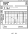
- Example graphics panels 320 are depicted for an example embodiment below with reference to Fig. 4 through FIG. 10D .
- FIG. 3 is a block diagram that illustrates an example set 600 of COO GUIs, according to an embodiment.
- FIG. 3 represents a site map for the web pages that make up the set 600 of GUIs.
- GUI 601 for a COO software application (COO app) landing page an example of which is depicted in FIG. 4 .
- GUIs 610, 620 and 630 for the three categories of COO parameters: ink, make-up and printer operation ("system", "power consumption”), respectively -- examples of which are depicted in FIG. 5 , FIG. 7 and FIG. 9 , respectively. All these GUIs are understood to include at least one of a printer ID area or date/time range area, or both; but, those areas are not shown in the following example GUIs of FIG. 5 through FIG. 10D to avoid clutter in those drawings.
- a user can navigate to a total ink usage (consumption) GUI 611 ( FIG. 8A ), a per code ink usage (consumption) GUI 612 ( FIG. 8B ), an ink cartridge waste GUI 613 ( FIG. 8C ) and ink recommendations GUI 614B ( FIG. 8D ).
- the reference to 614 in FIG. 3 includes 614A, 614B and 614C, which may be the same page, but the recommendations or suggestions are different according to the different COO parameter. Examples of an ink summary, total ink usage (including average use per hour), ink usage per code and ink cartridge waste are provided in FIGS. 7 , and 8A through FIG.
- a printer setting GUI 690 that is part of the control processor GUI 186 can be opened, to set one or more printer operation parameters to make use of the suggested cost reduction presented in ink suggestions GUI 614 (last.
- the recommendations block 614 may be configured to provide recommendations related to ink consumption, make-up consumption and printer operations. In other embodiments, the recommendations block 614 may display recommendations unique to each COO parameter.
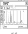
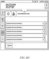
- a user can navigate to a make-up usage (consumption) versus ambient temperature over time GUI 621 ( FIG. 6A ), a make-up usage versus time GUI 622 ( FIG. 6B ), make-up waste per cartridge GUI 623 ( FIG. 6C ) and make-up recommendations GUI 614A ( FIG. 6D ).
- the printer setting GUI 690 can be opened, as described above for the ink recommendations GUI 614.
- Selecting an active area in panel 820b will cause the second level make-up usage over a selected time or average use over time GUI 622 to be presented, described below with reference to FIG. 6B .
- Graphic panel 820c indicates a summary of make-up cartridge waste, e.g., using characters indicating percentage remaining. Selecting an active area in panel 820c will cause the second level make-up cartridge waste GUI 623 to be presented, described below with reference to FIG. 6C .
- Graphic panel 820d indicates make-up COO suggestions, e.g., using a light bulb or checkmark bubble graphic. Selecting an active area in panel 820d will cause the second level make-up suggestions GUI 614 to be presented, described below with reference to FIG. 6D .
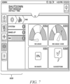
- FIG. 7 is a block diagram that illustrates an example first level COO GUI 610 for ink, according to an embodiment.
- There are navigation active areas 1020 including active areas for the top level and other first level GUI.
- the active area for the current first level GUI, ink is highlighted.
- Graphic panel 1020a indicates a summary of total ink usage, using a gas gauge dial graphic. Selecting an active area in panel 1020a will cause the second level total ink usage GUI 611 to be presented, described below with reference to FIG. 8A .
- Graphic panel 1020b indicates a summary of ink usage per code, e.g., using a gas gauge dial graphic for at least one code, such as the code associated with the most usage.
- Selecting an active area in panel 1020b will cause the second level per code ink usage GUI 612 to be presented, described below with reference to FIG. 8B .
- Graphic panel 1020c indicates a summary of ink cartridge waste, e.g., using characters indicating percentage remaining. Selecting an active area in panel 1020c will cause the second level ink cartridge waste GUI 613 to be presented. This GUI presented below in reference to FIG. 8C .
- Graphic panel 1020d indicates ink COO recommendations, e.g., using a light bulb or checkmark in balloon graphic. Selecting an active area in panel 1020d will cause the second level ink recommendations GUI 614 to be presented. This GUI is not presented below but is similar to the GUI described above with reference to FIG. 6D , but for ink suggestions.
- FIG. 8A through FIG. 8D are block diagrams that illustrate example second level (drill down) COO GUI for ink details, according to an embodiment.
- FIG. 8A is a block diagram of total ink usage GUI 611.
- a graphics panel includes a plot with a horizontal axis indicating time (within a range specified in a time/date range area 303 as provided in FIG. 2 ), and a vertical axis indicating ink usage. This plot is provided because a cost of operations is proportional to the ink used.
- a trace is plotted to indicate the usage history of the ink based on sensor and component data.
- FIG. 8B is a block diagram of per code ink usage GUI 612.
- a graphics panel includes a plot with a horizontal axis indicating code, and a vertical axis indicating ink usage (within a time range specified in a time/date range area 303, as specified in FIG. 2 ).
- a code is defined as a job within the printer - whatever set of information is to be printed onto each product.
- the ink usage is calculated based on the number of ink drops required to print that message, based on the length of the message, the current character height and width selected, and whether normal or bold, e.g., as described above with reference to Table 3.
- FIG. 8C is a block diagram of ink cartridge waste GUI 613.
- a graphics panel includes a table for cartridges used within the time range specified in a time/date range area 303 (as provide in FIG. 2 ).
- the first column holds text that indicates a serial number for the ink cartridge.
- the second column holds text that indicates the date the cartridge was inserted into the printer (date fitted).
- the third column holds text that indicates the date the cartridge was removed.
- the fourth column holds text that indicates the percent fill at the removal time. Since this amount was discarded with the cartridge, it represents make-up fluid wastage and contributes to a possibly avoidable cost of operation.
- Ink waste in this example may be the result of reaching the expiration date before the ink is entirely consumed, or a cartridge that is otherwise removed from the printer before it is entirely consumed, for example.
- FIG. 8D is a block diagram of make-up recommendations GUI 614 (B).
- a graphics panel includes one or more text entry active areas where a user can read or input recommendations on how to modify printer settings or other printer operation procedures to save costs associated with the ink fluid.
- the navigation panel includes an active area indicated by a gears icon to call up the printer setting GUI 690, as described above, so that the user can implement a recommendation.
- Selecting an active area in panel 1220b will cause the second level jetting waste GUI 632 to be presented, described below with reference to FIG. 10B .
- Graphic panel 1220c indicates a summary of downtime, e.g., using a gas gauge dial graphic or text box indicating downtime as a percentage of planned run time. Selecting an active area in panel 1220c will cause the second level downtime GUI 633 to be presented, described below with reference to FIG. 10C .
- Graphic panel 1220d indicates a summary of maintenance, e.g., using a thermometer to indicate temperature differences associated with filter replacement maintenance. Selecting an active area in panel 1220d will cause the second level maintenance GUI 634 to be presented, described below with reference to FIG. 10D .
- FIG. 10E is a block diagram of print operation recommendations GUI 614 C.
- a graphics panel includes one or more text entry active areas where a user can read or input recommendations on how to modify printer settings or other printer operation procedures to save costs associated with the print operations as defined herein.
- the navigation panel includes an active area indicated by a gears icon to call up the printer setting GUI 690, as described above, so that the user can implement a recommendation.
- another graphics panel (not shown) indicates printer operation suggestions, e.g., using a light bulb graphic or checkmark in balloon graphic. Selecting an active area in such a panel will cause the second level printer operation suggestion GUI 635 to be presented.
- FIG. 10A through FIG. 10D are block diagrams that illustrate example second level (drill down) COO GUI for printer operation details, according to an embodiment.
- FIG. 10A is a block diagram of power consumption GUI 631.
- a graphics panel includes a plot with a horizontal axis indicating time (within a range specified in a time/date range area 303, not shown), and a vertical axis indicating percentage of hours per day of power use. Two traces are plotted. Trace 1316 indicates how much of this time the printer is actually printing. Trace 1317 indicates wasted power, when the power is on but no printing is occurring. This plot is provided because excess cost of operations is proportional to the wasted power used, and the amount of wasted power used depends on when the power is on without actually printing.
- FIG. 10B is a block diagram of jetting waste or jetting efficiency GUI 632.
- a graphics panel includes a plot with a horizontal axis indicating time (within a range specified in a time/date range area 303, not shown), and a vertical axis indicating percentage of hours per day of power use. Two traces are plotted. Trace 1326 represents time spent printing. Trace 1327 represents wasteful running of the jet defined as "jet running but not actually printing.” This metric is important because running ink through ink jets causes solvent to evaporate off from the ink, and the printer needs to gulp make-up to replace that evaporated solvent. Thus, there is a cost to running jets. A user who runs the jets for periods of time when they are not printing therefore is consuming fluid that could be saved if the jets were turned off: - - a potential for cost savings.
- FIG. 10C is a block diagram of downtime GUI 633.
- a graphics panel includes a plot with a horizontal axis indicating a downtime type (e.g., cause by cartridge change, component repair/replace, sensor repair/replace, processor error, human error, etc.) and a vertical axis indicating hours lost (within a time range specified in a time/date range area 303, as provided in FIG. 2 ).
- a trace or bar graph is plotted to indicate the ink down time per type of incident based on sensor data. If within the time range, there are several occurrences (incidents) due to the same cause, those are distinguished by lines or color changes on each bar.
- Examples of incidents causing downtime may be high voltage (EHT) trips, gutter faults and charge errors, which may be the result of improper or lack of cleaning of the print head.
- EHT high voltage
- This plot is provided because a cost of operations is proportional to downtime and identifying causes that are associated with the most downtime can suggest where costs can be saved.
- a maintenance GUI is presented, not shown.
- a graphics panel includes a plot with a horizontal axis indicating time and a vertical axis indicating hours lost (within a time range specified in a time/date range area, not shown) due to maintenance activities, e.g., due to changing a filter because high pressure changes upstream and downstream of filter, or changing other components, or setting due to excessive ink temperatures. This plot is provided because a cost of operations is proportional to downtime for maintenance versus expense of equipment failure due to lack of maintenance.
- FIG. 10D is a block diagram of ink or cabinet temperature GUI 634.
- a graphics panel includes a plot with a horizontal axis indicating time and a vertical axis indicating temperature differences. This chart compares ink cabinet temperature to ambient temperature. If the temperature inside the ink cabinet is greater than the ambient temperature, then the main inlet [air] filter is clogged and needs attention. This is important for COO because higher-than-normal ink cabinet temperature will accelerate make-up consumption due to increased evaporation. So, the cost of downtime to perform maintenance, e.g., change filter, has to be weighed against the cost of lost make-up/solvent.
- an industrial printer While the above-described embodiments of an industrial printer have been described as a stand-alone printer with embedded software and controls, the invention may also be incorporated into communication networks for purposes of remote servicing of the industrial.
- An example of an industrial printer that is integrated with remote servicing technology that discloses the transmission of sensor to a remote processor to evaluate the condition of an industrial is disclosed in U.S. Patent No 9,524,132 , which is incorporated herein by reference.
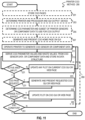
- the method 200 is performed by printer COO module 120, control process 180, one or more servers, or databases, or some combination. Although steps are depicted in FIG. 11 as integral steps in a particular order for purposes of illustration, in other embodiments, one or more steps, or portions thereof, are performed in a different order, or overlapping in time, in series or in parallel, or are omitted, or one or more additional steps are added, or the method is changed in some combination of ways.
- an active area is a portion of a display to which a user can point using a pointing device (such as a cursor and cursor movement device, or a touch screen) to cause an action to be initiated by the device that includes the display.
- a pointing device such as a cursor and cursor movement device, or a touch screen
- active areas are standalone buttons, radio buttons, check lists, pull down menus, scrolling lists, and text boxes, among others.
- the module 120 automatically determines the printer and processor and GUI output device that will interact with the module 120.
- the processor on which the module 120 executes is the only processor, but in some embodiments, the module 120 is operating on or interacting with a separate server at the facility or at a central site, and these other processors are identified during step 203.
- the module can be operating on a processor that is not built into a printer and the printer to be characterized by the module 120 is determined during step 203.
- the GUI can be displayed on an intended device that is not built into a printer and the device to display the GUI produced by the module 120 is determined during step 203.
- the values for the printer, processor and display device may be determined in any manner, such as: being received by a manual entry from a user in response to a prompt presented at a user interface, such as a graphical user interface; found included in the programming instructions; retrieved from a data structure on the local host or another host on a network, such as from one or more databases; received in a message from another host, either unsolicited or in response to a query; or some combination.
- step 205 the COO parameters and printer associated sensor data or components to use to generate CCO parameter values therefore are determined.
- the data indicating the COO parameter and sensor data and/or component data may be determined in any manner, such as: being received by a manual entry from a user in response to a prompt presented at a user interface, such as a graphical user interface; found included in the programming instructions; retrieved from a data structure on the local host or another host on a network, such as from one or more databases; received in a message from another host, either unsolicited or in response to a query; or some combination.
- the COO parameter values of interest to be derived from the printer sensor data and/or computer data include: ink usage per code, total ink usage, ink cartridge waste, make-up/solvent temperature, make up/solvent usage, make-up/solvent cartridge waste, power consumption, jetting waste, downtime, ink temperature, printer settings, or expert system suggestions for cost saving operations.
- _Ink usage is related to COO because ink is an ongoing cost of running a printer; reducing the quantity of ink used will reduce the cost of operating (COO) for running that piece of equipment.
- Make-up usage (also known as solvent usage) is related in the same way, and make-up temperature also impacts operating cost because solvent evaporates more rapidly at higher temperatures, so the printer must consume more make-up at higher temperatures to balance ink viscosity.
- Power consumption and jetting waste are related to COO because they involve the printer idling in an active state where it uses power and make-up for jetting even though it is not printing (jetting waste is a second cause of makeup/solvent waste), much like a car that is parked but not turned off wastes gasoline.
- jetting waste is a second cause of makeup/solvent waste
- the COO parameters of interest to be derived from the printer sensor data and/or computer data include: ink usage per code, total ink usage, ink cartridge waste, make-up/solvent temperature, make up/solvent usage, make-up/solvent cartridge waste, power consumption, jetting waste, downtime, ink temperature, printer settings, or expert system suggestions for cost saving operations.
- Ink usage is related to COO because ink is an ongoing cost of running a printer; reducing the quantity of ink used will reduce the cost of operating (COO) for running that piece of equipment.
- Make-up usage (also known as solvent usage) is related in the same way, and make-up temperature also impacts operating cost because solvent evaporates more rapidly at higher temperatures, so the printer must consume more make-up at higher temperatures to balance ink viscosity.
- Power consumption and jetting waste are related to COO because they involve the printer idling in an active state where it uses power and make-up for jetting even though it is not printing (jetting waste is a second cause of makeup/solvent waste), much like a car that is parked but not turned off wastes gasoline.
- jetting waste is a second cause of makeup/solvent waste
- the printer is operated to report one or more CCO parameter values derived from sensor data or component data.
- sensor data and/or component data is transmitted to the COO module 120 for processing by the module 120 and/or control processor 180.
- the COO module 120 and/or control processor 180 are configured to derive the COO parameter values, including COO waste values, based on the transmitted sensor data and/or component data that is indicative of the monitored COO parameters.
- COO parameters may include ink consumption, solvent consumption and printer operations (e.g. power consumption, ambient temperature, component temperature, non-printing jetting time, downtime etc.
- a value for each of one or more COO parameters are derived based at least in part on one or more of the subset of sensor data or component data, such as the corresponding sensors or components listed in the right column for each COO parameter.
- ambient temperature is calculated from the sensor value for cabinet temperature sensor as well as a sensor value for the voltage needed to heat the printhead.
- the derived values are stored in a data structure, such as the data structure described below with reference to FIG. 13 below, for subsequently generating graphics for the GUI.
- step 221 it is determined whether there has been any activation of an active area, e.g., a navigation active area 312 or an active area in a panel 320,such as a click or touch on an active area for the printer operation, make-up or ink graphic in FIG.4 , described above. If not, control passes to step 223 in which the current GUI is updated with any new value for a COO parameter derived, for example, from one or more new values from the subset of sensors or components. Control passes back from step 223 to step 211 to continue to operate the printer or report the sensor or component data
- step 241 it is determined whether the input indicates a different range for the context of the graphics (such as a plot) displayed on the current page of the GUI page presented on the GUI device.
- the input at the active area could indicate a different date range, a different time range, a different printer or set of printers, a different scale or range for a horizontal or vertical axis, a different unit for a horizontal or vertical axis, such as dollars instead of wasted ink amount, among others, alone or in some combination. If so, then in step 243 the graphics (such as a plot) is updated using the different ranges provided in the one or more active areas. Control then passes to step 251 whether step 233 was executed or not.
- the valid range field 415 holds data that indicates one or more values or ranges of values within which a user may select output for the sensor or component.
- the unit field 417 holds data that indicate the physical dimensions measured by the sensor or associated with the component data.
- the scaling field 419 holds data that indicates how to generate the physical dimensions represented by the measurement or data from the values stored, such as multiplicative factor or additive factor or a logarithmic function or exponential function or polynomial function or other function, or some combination, e.g., to convert a decimal value to an integer.
- the default value field 421 holds data that indicates a value used initially or in the absence of a value received from a sensor or component.
- the valid range field 515 holds data that indicates one or more values or ranges of values within which a value for the COO parameter is valid, e.g., in order to weed out erroneous derivations.
- the unit field 517 holds data that indicate the physical dimensions represented by the COO parameter.
- the scaling field 519 holds data that indicates how to generate the physical dimensions represented by the COO parameter from the values stored, such as multiplicative factor or additive factor or a logarithmic function or exponential function or polynomial function or other function, or some combination, e.g., to convert a decimal value to an integer.
- the default value field 521 holds data that indicates a value used initially or in the absence of a value derived from current sensor data.
- the time stamp field 531 holds data that indicates a time when a value for the TC0 parameter was derived from current sensor data.
- the value field 532 holds data that indicates the value for the COO parameter at the time of the time stamp.
- the ellipsis within the record 510a indicates other fields in the record, such as subsequent time stamp and value fields inserted when a COO parameter is subsequently derived.
- FIG. 12 is a block diagram that illustrates a computer system 1400 upon which an embodiment of the invention may be implemented.
- the computer system 1400 is shown coupled to printer 110 such as the industrial printer 110 as described herein.
- the communications may be wired or wireless.
- the printer 110 may include similar components as described by computer system 1400 and will not be duplicated.
- the assembly line 190 may be controlled by a computer system 1400 or a network server.
- the computing system may be a server having server applications running or being executed thereon.
- Computer system 1400 includes a communication mechanism such as a bus 1410 for passing information between other internal and external components of the computer system 1400.
- Information is represented as physical signals of a measurable phenomenon, typically electric voltages, but including, in other embodiments, such phenomena as magnetic, electromagnetic, pressure, chemical, molecular atomic and quantum interactions. For example, north and south magnetic fields, or a zero and non-zero electric voltage, represent two states (0, 1) of a binary digit (bit). Other phenomena can represent digits of a higher base. A superposition of multiple simultaneous quantum states before measurement represents a quantum bit (qubit). A sequence of one or more digits constitutes digital data that is used to represent a number or code for a character. In some embodiments, information called analog data is represented by a near continuum of measurable values within a particular range. Computer system 1400, or a portion thereof, constitutes a means for performing one or more steps of one or more methods described herein.
- a sequence of binary digits constitutes digital data that is used to represent a number or code for a character.
- a bus 1410 includes many parallel conductors of information so that information is transferred quickly among devices coupled to the bus 1410.
- One or more processors 1402 for processing information are coupled with the bus 1410.
- a processor 1402 performs a set of operations on information.
- the set of operations include bringing information in from the bus 1410 and placing information on the bus 1410.
- the set of operations also typically include comparing two or more units of information, shifting positions of units of information, and combining two or more units of information, such as by addition or multiplication.
- a sequence of operations to be executed by the processor 1402 constitute computer instructions.
- Computer system 1400 also includes a memory 1404 coupled to bus 1410.
- the memory 1404 such as a random-access memory (RAM) or other dynamic storage device, stores information including computer instructions. Dynamic memory allows information stored therein to be changed by the computer system 1400. RAM allows a unit of information stored at a location called a memory address to be stored and retrieved independently of information at neighboring addresses.
- the memory 1404 is also used by the processor 1402 to store temporary values during execution of computer instructions.
- the computer system 1400 also includes a read only memory (ROM) 1406 or other static storage device coupled to the bus 1410 for storing static information, including instructions, that is not changed by the computer system 1400.
- ROM read only memory
- Also coupled to bus 1410 is a non-volatile (persistent) storage device such as a magnetic disk or optical disk, for storing information, including instructions, that persists even when the computer system 1400 is turned off or otherwise loses power.
- Information is provided to the bus 1410 for use by the processor from an external input device 1412, such as a keyboard containing alphanumeric keys operated by a human user, or a sensor (such as touch sensitive surface.).
- an external input device 1412 such as a keyboard containing alphanumeric keys operated by a human user, or a sensor (such as touch sensitive surface.).
- a sensor detects conditions in its vicinity or as applied to a sensor surface and transforms those detections into signals compatible with the signals used to represent information in computer system 1400.
- Other external devices coupled to bus 1410 used primarily for interacting with humans, include a display device 1414, such as a cathode ray tube (CRT) or a liquid crystal display (LCD), for presenting images, and a pointing device 1416, such as a mouse or a trackball or cursor direction keys, for controlling a position of a small cursor image presented on the display 1414 and issuing commands associated with graphical elements presented on the display 1414.
- the external in put devices may be wired or wireless.
- special purpose hardware such as an application specific integrated circuit (IC) 1420
- IC application specific integrated circuit
- the special purpose hardware is configured to perform operations not performed by processor 1402 quickly enough for special purposes.
- application specific ICs include graphics accelerator cards for generating images for display 1414, cryptographic boards for encrypting and decrypting messages sent over a network, speech recognition, and interfaces to special external devices, such as robotic arms and scanning equipment that repeatedly perform some complex sequence of operations that are more efficiently implemented in hardware.
- Computer system 1400 also includes one or more instances of a communications interface 1470 coupled to bus 1410.
- Communication interface 1470 provides a two-way communication coupling to a variety of external devices that operate with their own processors, such as printers, scanners and external disks. In general the coupling is with a network link 1478 that is connected to a local network 1480 to which a variety of external devices with their own processors are connected.
- communication interface 1470 may be a parallel port or a serial port or a universal serial bus (USB) port on a personal computer.
- communications interface 1470 is an integrated services digital network (ISDN) card or a digital subscriber line (DSL) card or a telephone modem that provides an information communication connection to a corresponding type of telephone line.
- ISDN integrated services digital network
- DSL digital subscriber line
- a communication interface 1470 is a cable modem that converts signals on bus 1410 into signals for a communication connection over a coaxial cable or into optical signals for a communication connection over a fiber optic cable.
- communications interface 1470 may be a local area network (LAN) card to provide a data communication connection to a compatible LAN, such as Ethernet.
- LAN local area network
- Wireless links may also be implemented.
- Carrier waves, such as acoustic waves and electromagnetic waves, including radio, optical and infrared waves travel through space without wires or cables. Signals include man-made variations in amplitude, frequency, phase, polarization or other physical properties of carrier waves.
- the communications interface 1470 sends and receives electrical, acoustic or electromagnetic signals, including infrared and optical signals, that carry information streams, such as digital data.
- Non-volatile media include, for example, optical or magnetic disks, such as storage device 1408.
- Volatile media include, for example, dynamic memory 1404.
- Transmission media include, for example, coaxial cables, copper wire, fiber optic cables, and waves that travel through space without wires or cables, such as acoustic waves and electromagnetic waves, including radio, optical and infrared waves.
- the term computer-readable storage medium is used herein to refer to any medium that participates in providing information to processor 1402, except for transmission media.
- Computer-readable media include, for example, a floppy disk, a flexible disk, a hard disk, a magnetic tape, or any other magnetic medium, a compact disk ROM (CD-ROM), a digital video disk (DVD) or any other optical medium, punch cards, paper tape, or any other physical medium with patterns of holes, a RAM, a programmable ROM (PROM), an erasable PROM (EPROM), a FLASH-EPROM, or any other memory chip or cartridge, a carrier wave, or any other medium from which a computer can read.
- the term non-transitory computer-readable storage medium is used herein to refer to any medium that participates in providing information to processor 1402, except for carrier waves and other signals.
- Logic encoded in one or more tangible media includes one or both of processor instructions on a computer-readable storage media and special purpose hardware, such as ASIC 1420.
- Network link 1478 typically provides information communication through one or more networks to other devices that use or process the information.
- network link 1478 may provide a connection through local network 1480 to a host computer 1482 or to equipment 1484 operated by an Internet Service Provider (ISP).
- ISP equipment 1484 in turn provides data communication services through the public, world-wide packet-switching communication network of networks now commonly referred to as the Internet 1490.
- a computer called a server 1492 connected to the Internet provides a service in response to information received over the Internet.
- server 1492 provides information representing video data for presentation at display 1414.
- the invention is related to the use of computer system 1400 for implementing the techniques described herein. According to one embodiment of the invention, those techniques are performed by computer system 1400 in response to processor 1402 executing one or more sequences of one or more instructions contained in memory 1404. Such instructions, also called software and program code, may be read into memory 1404 from another computer-readable medium such as storage device 1408. Execution of the sequences of instructions contained in memory 1404 causes processor 1402 to perform the method steps described herein.
- hardware such as application specific integrated circuit 1420, may be used in place of or in combination with software to implement the invention. Thus, embodiments of the invention are not limited to any specific combination of hardware and software.
- Computer system 1400 can send and receive information, including program code, through the networks 1480, 1490 among others, through network link 1478 and communications interface 1470.
- a server 1492 transmits program code for a particular application, requested by a message sent from computer 1400, through Internet 1490, ISP equipment 1484, local network 1480 and communications interface 1470.
- the received code may be executed by processor 1402 as it is received, or may be stored in storage device 1408 or other non-volatile storage for later execution, or both. In this manner, computer system 1400 may obtain application program code in the form of a signal on a carrier wave.
- FIG. 13 illustrates a chip set 1500 upon which an embodiment of the invention may be implemented.
- Chip set 1500 is programmed to perform one or more steps of a method described herein and includes, for instance, the processor and memory components described with respect to FIG. 14 incorporated in one or more physical packages (e.g., chips).
- a physical package includes an arrangement of one or more materials, components, and/or wires on a structural assembly (e.g., a baseboard) to provide one or more characteristics such as physical strength, conservation of size, and/or limitation of electrical interaction.
- the chip set can be implemented in a single chip.
- Chip set 1500, or a portion thereof constitutes a means for performing one or more steps of a method described herein.
- the chip set 1500 includes a communication mechanism such as a bus 1501 for passing information among the components of the chip set 1500.
- a processor 1503 has connectivity to the bus 1501 to execute instructions and process information stored in, for example, a memory 1505.
- the processor 1503 may include one or more processing cores with each core configured to perform independently.
- a multi-core processor enables multiprocessing within a single physical package. Examples of a multi-core processor include two, four, eight, or greater numbers of processing cores.
- the processor 1503 may include one or more microprocessors configured in tandem via the bus 1501 to enable independent execution of instructions, pipelining, and multithreading.
- the processor 1503 may also be accompanied with one or more specialized components to perform certain processing functions and tasks such as one or more digital signal processors (DSP) 1507, or one or more application-specific integrated circuits (ASIC) 1509.
- DSP 1507 typically is configured to process real-world signals (e.g., sound) in real time independently of the processor 1503.
- ASIC 1509 can be configured to performed specialized functions not easily performed by a general purposed processor.
- Other specialized components to aid in performing the inventive functions described herein include one or more field programmable gate arrays (FPGA) (not shown), one or more controllers (not shown), or one or more other special-purpose computer chips.
- the controller may include hardware, software, firmware and/or a combination of hardware, software and firmware.
- the hardware of the controller may include analog circuitry and/or digital circuitry and interfaces for communicating with other component devices such as memory, user interfaces, drivers, and network communication interfaces, by way of non-limiting examples.
- the processor 1503 and accompanying components have connectivity to the memory 1505 via the bus 1501.
- the memory 1505 includes both dynamic memory (e.g., RAM, magnetic disk, writable optical disk, etc.) and static memory (e.g., ROM, CD-ROM, etc.) for storing executable instructions that when executed perform one or more steps of a method described herein.
- the memory 1505 also stores the data associated with or generated by the execution of one or more steps of the methods described herein.
Landscapes
- Engineering & Computer Science (AREA)
- Theoretical Computer Science (AREA)
- Physics & Mathematics (AREA)
- General Physics & Mathematics (AREA)
- Human Computer Interaction (AREA)
- General Engineering & Computer Science (AREA)
- Business, Economics & Management (AREA)
- Human Resources & Organizations (AREA)
- Economics (AREA)
- Strategic Management (AREA)
- Entrepreneurship & Innovation (AREA)
- Educational Administration (AREA)
- Development Economics (AREA)
- Biodiversity & Conservation Biology (AREA)
- Game Theory and Decision Science (AREA)
- Life Sciences & Earth Sciences (AREA)
- Marketing (AREA)
- Operations Research (AREA)
- Quality & Reliability (AREA)
- Tourism & Hospitality (AREA)
- General Business, Economics & Management (AREA)
- Accessory Devices And Overall Control Thereof (AREA)
- Ink Jet (AREA)
- Inking, Control Or Cleaning Of Printing Machines (AREA)
Claims (9)
- Verfahren, Folgendes umfassend:
Betreiben eines industriellen Druckers (110), um auf ein Produktsubstrat zu drucken:während des Betriebs des Druckers Erzeugen von Sensordaten und/oder Komponentendaten, die dem Betrieb des industriellen Druckers zugeordneten Betriebskosten(COO)-Druckerparametern zugeordnet sind;Speichern, auf einem computerlesbaren Medium, auf das durch einen Prozessor zugegriffen werden kann, der Sensordaten und/oder Komponentendaten;Ableiten, basierend auf den Sensordaten und/oder Komponentendaten, eines oder mehrerer COO-Parameterwerte und zugeordneter COO-Verschwendungswerte, wobei die Ableitung dieser Werte dynamisch auf einer Echtzeitbasis mit aktuellen Sensordaten und Komponentendaten geschieht, wobei die COO-Verschwendungswerte mindestens eines von Folgenden umfassen;eine erste Menge von nicht verwendeter Druckfarbe oder nicht verwendetem Lösemittel in einer entfernten Patrone aus dem Drucker relativ zu einer zweiten Menge von Druckfarbe oder Lösemittel in einer in den Drucker eingesetzten Patrone;eine Menge von Strom oder Druckfarbe oder Lösemittel, die verbraucht wird, wenn der Drucker aktiviert ist und keine Druckvorgänge durchführt;Jetting-Verschwendung, die basierend auf dem Vergleichen einer Zeit, für die der Drucker Druckvorgänge durchführt, mit einer Zeit, für die das Jetting eingeschaltet ist, bestimmt wird,Druckfarbenverschwendung, die basierend auf dem Erreichen eines Ablaufdatums auf einer Druckfarbenpatrone, bevor die Patrone leer ist, bestimmt wird,eines oder mehrere von Umgebungstemperatur, Komponentenbetriebstemperatur, Stillstand, nicht-druckender Jetting-Zeit relativ zu einem oder mehreren von Druckfarbenverbrauch, Lösemittelverbrauch und Stromverbrauch, odereine Menge von Lösemittel, die verbraucht wird, wenn eine Umgebungstemperatur einen Schwellenpegel überschreitet; unddynamisches Anzeigen, auf einer Echtzeitbasis, einer ersten graphischen Benutzeroberfläche (115), einschließlich eines oder mehrerer abgeleiteter COO-Parameterwerte, die einen oder mehrere COO-Verschwendungswerte einschließen. - Verfahren nach Anspruch 1, wobei eine oder mehrere der COO-Druckerparameter ausgewählt sind aus der Gruppe umfassend Druckfarbenverbrauch, Lösemittelverbrauch und/oder Druckervorgänge, oder jegliche Kombinationen davon.
- Verfahren nach Anspruch 2, wobei der eine oder die mehreren abgeleiteten COO-Parameterwerte Druckfarbenverbrauchsverschwendungswerte, Lösemittelverbrauchsverschwendungswerte und Stromverbrauchsverschwendungswerte einschließen.
- Verfahren nach Anspruch 1, ferner umfassend das dynamische Erzeugen und Anzeigen einer zweiten graphischen Benutzeroberfläche einschließlich kostensparender Empfehlungen relativ zu den bestimmten COO-Parameterwerten und/oder COO-Verschwendungswerten, einschließlich des Anpassens der dem Betrieb des Druckers zugeordneten COO-Druckerparameter.
- Verfahren nach Anspruch 1 oder 2, wobei dem Druckfarbenverbrauch und dem Lösemittelverbrauch zugeordnete COO-Verschwendungswerte bestimmt werden, basierend darauf, dass Druckfarbe und Lösemittel über einen ausgewählten Zeitraum verbraucht werden und während dessen Druckfarbe oder Lösemittel während Druckervorgängen und nicht-druckenden Jetting-Zeiten verbraucht wird.
- Verfahren nach Anspruch 1 oder 2, wobei den Druckfarbenverbrauch- und Lösemittelverbrauch-COO-Druckerparametern zugeordnete Sensordaten und/oder Komponentendaten Daten umfassen, die sich auf Ablaufansammlung, tatsächliche Temperatur des Erhitzers, Erhitzerantriebsprozentsatz, Laufzeiten der Druckfarbenpumpe, Flüssigkeitsstand der Druckfarbe, Flüssigkeitsstand des Druckfarbenbehälters, Seriennummer der Druckfarbenpatrone, Ablaufdatum der Druckfarbenpatrone, Flüssigkeitsstand der Druckfarbenpatrone, Seriennummer der Lösemittelpatrone, Ablaufdatum der Lösemittelpatrone und Flüssigkeitsstand der Lösemittelpatrone, Gesamt-Druckfarbenverbrauch, Gesamt-Lösemittelverbrauch, Umgebungstemperatur, Druckfarbentemperatur und Lösemitteltemperatur, Stillstand und Druckereinstellungen beziehen.
- Verfahren nach Anspruch 1, 2 oder 3, wobei dem Druckfarbenverbrauch und/oder dem Lösemittelverbrauch zugeordnete COO-Parameterwerte einen oder mehrere von Druckfarbenverbrauch und Lösemittelverbrauch pro Code, Gesamt-Druckfarben- und Gesamt-Lösemittelverbrauch relativ zu einem ausgewählten Zeitraum, und/oder Lösemittelverbrauch während nicht-druckender Jetting-Zeit einschließen.
- Verfahren nach Anspruch 1, wobei COO-Druckerbetriebsparameter Stromverbrauch, Jetting-Effizienz, Stillstand und/oder Druckfarbentemperatur umfassen.
- Vorrichtung, Folgendes umfassend:
einen industriellen Drucker, der mit einer Stromversorgung gekoppelt ist, und der Drucker umfasst Folgendes:eine oder mehrere Druckfarbenpatronen beinhaltend Druckfarbe in Fluidverbindung mit einem Druckfarbenbehälter zum Drucken;eine oder mehrere Lösemittelpatronen beinhaltend Lösemittel in Fluidverbindung mit dem Druckfarbenbehälter, um dem Druckfarbenbehälter Lösemittel zum Drucken zu liefern;einen oder mehrere Sensoren und/oder eine oder mehrere Datenerfassungsvorrichtungen, die einem oder mehreren COO-Parametern zugeordnete Sensordaten oder Komponentendaten erzeugen;mindestens einen Prozessor; undphysisches und nichtflüchtiges computerlesbares Medium, das Anweisungen aufweist, die bei Ausführung durch den Prozessor den Prozessor veranlassen, das Verfahren nach einem der vorhergehenden Ansprüche durchzuführen.
Applications Claiming Priority (3)
| Application Number | Priority Date | Filing Date | Title |
|---|---|---|---|
| US201862671990P | 2018-05-15 | 2018-05-15 | |
| US201862716416P | 2018-08-09 | 2018-08-09 | |
| PCT/US2019/032531 WO2019222430A1 (en) | 2018-05-15 | 2019-05-15 | System and method for operating an industrial printer |
Publications (3)
| Publication Number | Publication Date |
|---|---|
| EP3793832A1 EP3793832A1 (de) | 2021-03-24 |
| EP3793832A4 EP3793832A4 (de) | 2022-03-16 |
| EP3793832B1 true EP3793832B1 (de) | 2025-07-02 |
Family
ID=68540797
Family Applications (1)
| Application Number | Title | Priority Date | Filing Date |
|---|---|---|---|
| EP19803719.4A Active EP3793832B1 (de) | 2018-05-15 | 2019-05-15 | System und verfahren zum betrieb eines industriellen druckers |
Country Status (4)
| Country | Link |
|---|---|
| US (1) | US11307810B2 (de) |
| EP (1) | EP3793832B1 (de) |
| CN (1) | CN112368148B (de) |
| WO (1) | WO2019222430A1 (de) |
Families Citing this family (7)
| Publication number | Priority date | Publication date | Assignee | Title |
|---|---|---|---|---|
| JP7200621B2 (ja) * | 2018-11-22 | 2023-01-10 | セイコーエプソン株式会社 | 電子機器 |
| EP4168253A4 (de) * | 2020-07-29 | 2024-05-15 | Hewlett-Packard Development Company, L.P. | Wartung von druckvorrichtungen |
| US12246540B2 (en) | 2020-11-20 | 2025-03-11 | Hewlett-Packard Development Company, L.P. | Profile governing servicing maintenance of fluidic printhead nozzles |
| JP7711431B2 (ja) * | 2021-06-03 | 2025-07-23 | コニカミノルタ株式会社 | 生産設備モニタリングシステム及び生産設備モニタリング方法、並びに、印刷システム |
| CN115476582B (zh) * | 2021-06-16 | 2025-05-27 | 海德堡印刷机械股份公司 | 用于利用印刷机印刷印刷作业的方法 |
| US11755863B1 (en) * | 2022-03-02 | 2023-09-12 | Ricoh Company, Ltd. | Ink estimation model updates for production printers |
| US11775791B2 (en) * | 2022-03-02 | 2023-10-03 | Ricoh Company, Ltd. | Cloud-based parallel ink estimation for production printers |
Family Cites Families (19)
| Publication number | Priority date | Publication date | Assignee | Title |
|---|---|---|---|---|
| JP3065053B2 (ja) * | 1998-01-06 | 2000-07-12 | セイコーエプソン株式会社 | 機器監視システム、ローカル監視装置、統合監視装置、機器監視方法、及び、プログラムを格納したコンピュータ可読媒体 |
| US20040169888A1 (en) * | 2003-02-28 | 2004-09-02 | Eveland Michael J. | Method and apparatus for printing on a partially-printed medium |
| US6908558B2 (en) * | 2003-03-19 | 2005-06-21 | David J. Stinson | Fountain solution recycling system for commercial printers |
| GB2413451B (en) * | 2004-04-23 | 2006-04-26 | Myfotowall Ltd | Wallpaper printing system |
| JP2006004054A (ja) * | 2004-06-16 | 2006-01-05 | Sharp Corp | 電子機器のユーザインターフェイス生成装置 |
| US7748918B2 (en) * | 2006-11-17 | 2010-07-06 | International Business Machines Corporation | Printer paper waste reduction method and computer program product |
| JP5338204B2 (ja) * | 2007-12-11 | 2013-11-13 | セイコーエプソン株式会社 | 液体供給装置、液体噴射装置、及び液体供給方法 |
| CN101593087A (zh) * | 2008-05-29 | 2009-12-02 | 福建升腾资讯有限公司 | 基于wince系统的打印预览方法 |
| US20090322808A1 (en) * | 2008-06-30 | 2009-12-31 | Infoprint Solutions Company Llc | Method and apparatus for determining real time ink volume in a printer |
| FR2954215A1 (fr) * | 2009-12-23 | 2011-06-24 | Markem Imaje | Systeme de determination de l'autonomie en fluides consommables d'une imprimante a jet d'encre continu |
| US8491075B2 (en) * | 2011-02-09 | 2013-07-23 | Xerox Corporation | Method and apparatus for controlling jetting performance in an inkjet printer |
| WO2014118766A1 (en) * | 2013-01-31 | 2014-08-07 | Hewlett-Packard Industrial Printing Ltd. | Printer and image processing |
| CN103434262B (zh) * | 2013-06-24 | 2016-01-13 | 宁波欣达印刷机器有限公司 | 凹版印刷机精确进入套印位置的方法 |
| CN105873765B (zh) * | 2014-01-03 | 2017-11-17 | 惠普发展公司,有限责任合伙企业 | 具有集成的墨水液位传感器的液体喷射设备 |
| JP6387718B2 (ja) * | 2014-07-15 | 2018-09-12 | セイコーエプソン株式会社 | 印刷画像処理装置、印刷画像処理システム、および印刷画像選択画面の表示方法 |
| BR112017007004B1 (pt) * | 2014-10-07 | 2023-03-07 | Videojet Technologies Inc | Método e sistema para a manutenção remota de uma impressora industrial |
| US10209235B2 (en) * | 2015-05-04 | 2019-02-19 | Deere & Company | Sensing and surfacing of crop loss data |
| KR102721890B1 (ko) * | 2015-12-10 | 2024-10-24 | 메르크 파텐트 게엠베하 | 비-방향족 사이클을 함유하는 케톤을 포함하는 제형 |
| US10318220B2 (en) * | 2017-08-09 | 2019-06-11 | Eastman Kodak Company | Cost-target-dependent printing using recipient demographics |
-
2019
- 2019-05-15 WO PCT/US2019/032531 patent/WO2019222430A1/en not_active Ceased
- 2019-05-15 CN CN201980047490.1A patent/CN112368148B/zh active Active
- 2019-05-15 EP EP19803719.4A patent/EP3793832B1/de active Active
- 2019-05-15 US US17/055,442 patent/US11307810B2/en active Active
Also Published As
| Publication number | Publication date |
|---|---|
| EP3793832A1 (de) | 2021-03-24 |
| WO2019222430A9 (en) | 2019-12-19 |
| CN112368148A (zh) | 2021-02-12 |
| WO2019222430A1 (en) | 2019-11-21 |
| CN112368148B (zh) | 2022-08-16 |
| US11307810B2 (en) | 2022-04-19 |
| EP3793832A4 (de) | 2022-03-16 |
| US20210191666A1 (en) | 2021-06-24 |
Similar Documents
| Publication | Publication Date | Title |
|---|---|---|
| EP3793832B1 (de) | System und verfahren zum betrieb eines industriellen druckers | |
| EP3966021B1 (de) | System und verfahren zur markierung von substraten mit verbesserter zeilenwiederherstellungszeit | |
| CN112204483A (zh) | 用于利用工业印刷机跟踪生产线生产率的系统和方法 | |
| JP4959466B2 (ja) | 値札プリンターにおける消費税率変更装置および消費税率変更方法 | |
| US20130085901A1 (en) | Inventory management system | |
| US11813878B2 (en) | Printer with printhead replacement detection and method for printhead replacement detection | |
| WO2016057465A1 (en) | System and method for remotely servicing an industrial printer | |
| US20190042170A1 (en) | Server system, terminal device, operating information collection system, program, server system operating method, and terminal device operating method | |
| CN102729638A (zh) | 控制装置、信息处理装置及控制装置的控制方法 | |
| JP7084748B2 (ja) | 管理サーバ | |
| CN102473273A (zh) | 消耗部件销售系统、电子商店提供装置、控制方法以及程序 | |
| CN101350738A (zh) | 设备、维护支援装置和支援系统 | |
| US7490055B2 (en) | Identification card manufacturing system supply ordering and diagnostic report | |
| JP2013148977A (ja) | 情報印刷装置 | |
| WO2017022602A1 (ja) | 情報処理装置、プログラム、プリンタ、情報処理システム | |
| JP2015170216A (ja) | 情報処理装置及び印刷装置及びそれらの制御方法、並びに、印刷システム | |
| US10838666B2 (en) | Inkjet recording apparatus system and display unit | |
| JP2023172489A (ja) | 情報処理装置、ヘッド管理方法、及びヘッド管理システム | |
| CN114489527A (zh) | 一种工业打印机可视化管理方法、装置及设备 | |
| JP6051387B2 (ja) | 抽選機能付プリンタ− | |
| US9952811B1 (en) | System for providing an alternative control interface to specialty devices | |
| JP2025164790A (ja) | 表示方法、電子機器、プログラム、及び管理システム | |
| JP2011186514A (ja) | Posシステム装置 | |
| JP2015219776A (ja) | 電子機器、電子秤装置およびプログラム | |
| JP2014019080A (ja) | 熱転写型プリンタおよび熱転写型プリンタシステム |
Legal Events
| Date | Code | Title | Description |
|---|---|---|---|
| STAA | Information on the status of an ep patent application or granted ep patent |
Free format text: STATUS: THE INTERNATIONAL PUBLICATION HAS BEEN MADE |
|
| PUAI | Public reference made under article 153(3) epc to a published international application that has entered the european phase |
Free format text: ORIGINAL CODE: 0009012 |
|
| STAA | Information on the status of an ep patent application or granted ep patent |
Free format text: STATUS: REQUEST FOR EXAMINATION WAS MADE |
|
| 17P | Request for examination filed |
Effective date: 20201214 |
|
| AK | Designated contracting states |
Kind code of ref document: A1 Designated state(s): AL AT BE BG CH CY CZ DE DK EE ES FI FR GB GR HR HU IE IS IT LI LT LU LV MC MK MT NL NO PL PT RO RS SE SI SK SM TR |
|
| AX | Request for extension of the european patent |
Extension state: BA ME |
|
| DAV | Request for validation of the european patent (deleted) | ||
| DAX | Request for extension of the european patent (deleted) | ||
| A4 | Supplementary search report drawn up and despatched |
Effective date: 20220210 |
|
| RIC1 | Information provided on ipc code assigned before grant |
Ipc: G06F 3/12 20060101ALI20220204BHEP Ipc: B41J 29/38 20060101ALI20220204BHEP Ipc: B41J 11/00 20060101ALI20220204BHEP Ipc: B41F 33/00 20060101AFI20220204BHEP |
|
| P01 | Opt-out of the competence of the unified patent court (upc) registered |
Effective date: 20230530 |
|
| GRAP | Despatch of communication of intention to grant a patent |
Free format text: ORIGINAL CODE: EPIDOSNIGR1 |
|
| STAA | Information on the status of an ep patent application or granted ep patent |
Free format text: STATUS: GRANT OF PATENT IS INTENDED |
|
| INTG | Intention to grant announced |
Effective date: 20240904 |
|
| RIN1 | Information on inventor provided before grant (corrected) |
Inventor name: HUTCHINSON, TIMOTHY Inventor name: MCCORMICK, MICHAEL Inventor name: SMITH, ROBERT |
|
| GRAJ | Information related to disapproval of communication of intention to grant by the applicant or resumption of examination proceedings by the epo deleted |
Free format text: ORIGINAL CODE: EPIDOSDIGR1 |
|
| STAA | Information on the status of an ep patent application or granted ep patent |
Free format text: STATUS: REQUEST FOR EXAMINATION WAS MADE |
|
| GRAP | Despatch of communication of intention to grant a patent |
Free format text: ORIGINAL CODE: EPIDOSNIGR1 |
|
| STAA | Information on the status of an ep patent application or granted ep patent |
Free format text: STATUS: GRANT OF PATENT IS INTENDED |
|
| INTC | Intention to grant announced (deleted) | ||
| INTG | Intention to grant announced |
Effective date: 20250122 |
|
| GRAS | Grant fee paid |
Free format text: ORIGINAL CODE: EPIDOSNIGR3 |
|
| GRAA | (expected) grant |
Free format text: ORIGINAL CODE: 0009210 |
|
| STAA | Information on the status of an ep patent application or granted ep patent |
Free format text: STATUS: THE PATENT HAS BEEN GRANTED |
|
| AK | Designated contracting states |
Kind code of ref document: B1 Designated state(s): AL AT BE BG CH CY CZ DE DK EE ES FI FR GB GR HR HU IE IS IT LI LT LU LV MC MK MT NL NO PL PT RO RS SE SI SK SM TR |
|
| REG | Reference to a national code |
Ref country code: GB Ref legal event code: FG4D |
|
| REG | Reference to a national code |
Ref country code: CH Ref legal event code: EP |
|
| REG | Reference to a national code |
Ref country code: DE Ref legal event code: R096 Ref document number: 602019072004 Country of ref document: DE |
|
| REG | Reference to a national code |
Ref country code: IE Ref legal event code: FG4D |
|
| REG | Reference to a national code |
Ref country code: NL Ref legal event code: MP Effective date: 20250702 |
|
| PG25 | Lapsed in a contracting state [announced via postgrant information from national office to epo] |
Ref country code: PT Free format text: LAPSE BECAUSE OF FAILURE TO SUBMIT A TRANSLATION OF THE DESCRIPTION OR TO PAY THE FEE WITHIN THE PRESCRIBED TIME-LIMIT Effective date: 20251103 |
|
| PG25 | Lapsed in a contracting state [announced via postgrant information from national office to epo] |
Ref country code: NL Free format text: LAPSE BECAUSE OF FAILURE TO SUBMIT A TRANSLATION OF THE DESCRIPTION OR TO PAY THE FEE WITHIN THE PRESCRIBED TIME-LIMIT Effective date: 20250702 |
|
| REG | Reference to a national code |
Ref country code: AT Ref legal event code: MK05 Ref document number: 1808814 Country of ref document: AT Kind code of ref document: T Effective date: 20250702 |
|
| PG25 | Lapsed in a contracting state [announced via postgrant information from national office to epo] |
Ref country code: IS Free format text: LAPSE BECAUSE OF FAILURE TO SUBMIT A TRANSLATION OF THE DESCRIPTION OR TO PAY THE FEE WITHIN THE PRESCRIBED TIME-LIMIT Effective date: 20251102 |
|
| PG25 | Lapsed in a contracting state [announced via postgrant information from national office to epo] |
Ref country code: NO Free format text: LAPSE BECAUSE OF FAILURE TO SUBMIT A TRANSLATION OF THE DESCRIPTION OR TO PAY THE FEE WITHIN THE PRESCRIBED TIME-LIMIT Effective date: 20251002 |
|
| REG | Reference to a national code |
Ref country code: LT Ref legal event code: MG9D |
|
| PG25 | Lapsed in a contracting state [announced via postgrant information from national office to epo] |
Ref country code: AT Free format text: LAPSE BECAUSE OF FAILURE TO SUBMIT A TRANSLATION OF THE DESCRIPTION OR TO PAY THE FEE WITHIN THE PRESCRIBED TIME-LIMIT Effective date: 20250702 |
|
| PG25 | Lapsed in a contracting state [announced via postgrant information from national office to epo] |
Ref country code: FI Free format text: LAPSE BECAUSE OF FAILURE TO SUBMIT A TRANSLATION OF THE DESCRIPTION OR TO PAY THE FEE WITHIN THE PRESCRIBED TIME-LIMIT Effective date: 20250702 |
|
| PG25 | Lapsed in a contracting state [announced via postgrant information from national office to epo] |
Ref country code: HR Free format text: LAPSE BECAUSE OF FAILURE TO SUBMIT A TRANSLATION OF THE DESCRIPTION OR TO PAY THE FEE WITHIN THE PRESCRIBED TIME-LIMIT Effective date: 20250702 |
|
| PG25 | Lapsed in a contracting state [announced via postgrant information from national office to epo] |
Ref country code: GR Free format text: LAPSE BECAUSE OF FAILURE TO SUBMIT A TRANSLATION OF THE DESCRIPTION OR TO PAY THE FEE WITHIN THE PRESCRIBED TIME-LIMIT Effective date: 20251003 |
|
| PG25 | Lapsed in a contracting state [announced via postgrant information from national office to epo] |
Ref country code: SE Free format text: LAPSE BECAUSE OF FAILURE TO SUBMIT A TRANSLATION OF THE DESCRIPTION OR TO PAY THE FEE WITHIN THE PRESCRIBED TIME-LIMIT Effective date: 20250702 Ref country code: CZ Free format text: LAPSE BECAUSE OF FAILURE TO SUBMIT A TRANSLATION OF THE DESCRIPTION OR TO PAY THE FEE WITHIN THE PRESCRIBED TIME-LIMIT Effective date: 20250702 |
|
| PG25 | Lapsed in a contracting state [announced via postgrant information from national office to epo] |
Ref country code: LV Free format text: LAPSE BECAUSE OF FAILURE TO SUBMIT A TRANSLATION OF THE DESCRIPTION OR TO PAY THE FEE WITHIN THE PRESCRIBED TIME-LIMIT Effective date: 20250702 |
|
| PG25 | Lapsed in a contracting state [announced via postgrant information from national office to epo] |
Ref country code: BG Free format text: LAPSE BECAUSE OF FAILURE TO SUBMIT A TRANSLATION OF THE DESCRIPTION OR TO PAY THE FEE WITHIN THE PRESCRIBED TIME-LIMIT Effective date: 20250702 Ref country code: PL Free format text: LAPSE BECAUSE OF FAILURE TO SUBMIT A TRANSLATION OF THE DESCRIPTION OR TO PAY THE FEE WITHIN THE PRESCRIBED TIME-LIMIT Effective date: 20250702 |
|
| PG25 | Lapsed in a contracting state [announced via postgrant information from national office to epo] |
Ref country code: RS Free format text: LAPSE BECAUSE OF FAILURE TO SUBMIT A TRANSLATION OF THE DESCRIPTION OR TO PAY THE FEE WITHIN THE PRESCRIBED TIME-LIMIT Effective date: 20251002 |
|
| PG25 | Lapsed in a contracting state [announced via postgrant information from national office to epo] |
Ref country code: ES Free format text: LAPSE BECAUSE OF FAILURE TO SUBMIT A TRANSLATION OF THE DESCRIPTION OR TO PAY THE FEE WITHIN THE PRESCRIBED TIME-LIMIT Effective date: 20250702 |
|
| PG25 | Lapsed in a contracting state [announced via postgrant information from national office to epo] |
Ref country code: SM Free format text: LAPSE BECAUSE OF FAILURE TO SUBMIT A TRANSLATION OF THE DESCRIPTION OR TO PAY THE FEE WITHIN THE PRESCRIBED TIME-LIMIT Effective date: 20250702 |
|
| PG25 | Lapsed in a contracting state [announced via postgrant information from national office to epo] |
Ref country code: DK Free format text: LAPSE BECAUSE OF FAILURE TO SUBMIT A TRANSLATION OF THE DESCRIPTION OR TO PAY THE FEE WITHIN THE PRESCRIBED TIME-LIMIT Effective date: 20250702 |
|
| PG25 | Lapsed in a contracting state [announced via postgrant information from national office to epo] |
Ref country code: IT Free format text: LAPSE BECAUSE OF FAILURE TO SUBMIT A TRANSLATION OF THE DESCRIPTION OR TO PAY THE FEE WITHIN THE PRESCRIBED TIME-LIMIT Effective date: 20250702 |