EP3794193B1 - Dispositif de guidage pour une porte coulissante et procédé de montage d'un rail de guidage - Google Patents
Dispositif de guidage pour une porte coulissante et procédé de montage d'un rail de guidage Download PDFInfo
- Publication number
- EP3794193B1 EP3794193B1 EP19725145.7A EP19725145A EP3794193B1 EP 3794193 B1 EP3794193 B1 EP 3794193B1 EP 19725145 A EP19725145 A EP 19725145A EP 3794193 B1 EP3794193 B1 EP 3794193B1
- Authority
- EP
- European Patent Office
- Prior art keywords
- guide rail
- mounting
- mounting part
- holder
- guide
- Prior art date
- Legal status (The legal status is an assumption and is not a legal conclusion. Google has not performed a legal analysis and makes no representation as to the accuracy of the status listed.)
- Active
Links
Images







Classifications
-
- E—FIXED CONSTRUCTIONS
- E05—LOCKS; KEYS; WINDOW OR DOOR FITTINGS; SAFES
- E05D—HINGES OR SUSPENSION DEVICES FOR DOORS, WINDOWS OR WINGS
- E05D15/00—Suspension arrangements for wings
- E05D15/06—Suspension arrangements for wings for wings sliding horizontally more or less in their own plane
- E05D15/0621—Details, e.g. suspension or supporting guides
- E05D15/0626—Details, e.g. suspension or supporting guides for wings suspended at the top
- E05D15/0652—Tracks
-
- E—FIXED CONSTRUCTIONS
- E05—LOCKS; KEYS; WINDOW OR DOOR FITTINGS; SAFES
- E05F—DEVICES FOR MOVING WINGS INTO OPEN OR CLOSED POSITION; CHECKS FOR WINGS; WING FITTINGS NOT OTHERWISE PROVIDED FOR, CONCERNED WITH THE FUNCTIONING OF THE WING
- E05F5/00—Braking devices, e.g. checks; Stops; Buffers
- E05F5/003—Braking devices, e.g. checks; Stops; Buffers for sliding wings
-
- E—FIXED CONSTRUCTIONS
- E05—LOCKS; KEYS; WINDOW OR DOOR FITTINGS; SAFES
- E05Y—INDEXING SCHEME ASSOCIATED WITH SUBCLASSES E05D AND E05F, RELATING TO CONSTRUCTION ELEMENTS, ELECTRIC CONTROL, POWER SUPPLY, POWER SIGNAL OR TRANSMISSION, USER INTERFACES, MOUNTING OR COUPLING, DETAILS, ACCESSORIES, AUXILIARY OPERATIONS NOT OTHERWISE PROVIDED FOR, APPLICATION THEREOF
- E05Y2201/00—Constructional elements; Accessories therefor
- E05Y2201/40—Motors; Magnets; Springs; Weights; Accessories therefor
- E05Y2201/404—Function thereof
- E05Y2201/41—Function thereof for closing
- E05Y2201/412—Function thereof for closing for the final closing movement
-
- E—FIXED CONSTRUCTIONS
- E05—LOCKS; KEYS; WINDOW OR DOOR FITTINGS; SAFES
- E05Y—INDEXING SCHEME ASSOCIATED WITH SUBCLASSES E05D AND E05F, RELATING TO CONSTRUCTION ELEMENTS, ELECTRIC CONTROL, POWER SUPPLY, POWER SIGNAL OR TRANSMISSION, USER INTERFACES, MOUNTING OR COUPLING, DETAILS, ACCESSORIES, AUXILIARY OPERATIONS NOT OTHERWISE PROVIDED FOR, APPLICATION THEREOF
- E05Y2600/00—Mounting or coupling arrangements for elements provided for in this subclass
- E05Y2600/50—Mounting methods; Positioning
- E05Y2600/52—Toolless
- E05Y2600/528—Hooking, e.g. using bayonets; Locking
-
- E—FIXED CONSTRUCTIONS
- E05—LOCKS; KEYS; WINDOW OR DOOR FITTINGS; SAFES
- E05Y—INDEXING SCHEME ASSOCIATED WITH SUBCLASSES E05D AND E05F, RELATING TO CONSTRUCTION ELEMENTS, ELECTRIC CONTROL, POWER SUPPLY, POWER SIGNAL OR TRANSMISSION, USER INTERFACES, MOUNTING OR COUPLING, DETAILS, ACCESSORIES, AUXILIARY OPERATIONS NOT OTHERWISE PROVIDED FOR, APPLICATION THEREOF
- E05Y2600/00—Mounting or coupling arrangements for elements provided for in this subclass
- E05Y2600/50—Mounting methods; Positioning
- E05Y2600/56—Positioning, e.g. re-positioning, or pre-mounting
-
- E—FIXED CONSTRUCTIONS
- E05—LOCKS; KEYS; WINDOW OR DOOR FITTINGS; SAFES
- E05Y—INDEXING SCHEME ASSOCIATED WITH SUBCLASSES E05D AND E05F, RELATING TO CONSTRUCTION ELEMENTS, ELECTRIC CONTROL, POWER SUPPLY, POWER SIGNAL OR TRANSMISSION, USER INTERFACES, MOUNTING OR COUPLING, DETAILS, ACCESSORIES, AUXILIARY OPERATIONS NOT OTHERWISE PROVIDED FOR, APPLICATION THEREOF
- E05Y2800/00—Details, accessories and auxiliary operations not otherwise provided for
- E05Y2800/20—Combinations of elements
- E05Y2800/205—Combinations of elements forming a unit
-
- E—FIXED CONSTRUCTIONS
- E05—LOCKS; KEYS; WINDOW OR DOOR FITTINGS; SAFES
- E05Y—INDEXING SCHEME ASSOCIATED WITH SUBCLASSES E05D AND E05F, RELATING TO CONSTRUCTION ELEMENTS, ELECTRIC CONTROL, POWER SUPPLY, POWER SIGNAL OR TRANSMISSION, USER INTERFACES, MOUNTING OR COUPLING, DETAILS, ACCESSORIES, AUXILIARY OPERATIONS NOT OTHERWISE PROVIDED FOR, APPLICATION THEREOF
- E05Y2800/00—Details, accessories and auxiliary operations not otherwise provided for
- E05Y2800/40—Physical or chemical protection
- E05Y2800/409—Physical or chemical protection against faulty mounting or coupling
-
- E—FIXED CONSTRUCTIONS
- E05—LOCKS; KEYS; WINDOW OR DOOR FITTINGS; SAFES
- E05Y—INDEXING SCHEME ASSOCIATED WITH SUBCLASSES E05D AND E05F, RELATING TO CONSTRUCTION ELEMENTS, ELECTRIC CONTROL, POWER SUPPLY, POWER SIGNAL OR TRANSMISSION, USER INTERFACES, MOUNTING OR COUPLING, DETAILS, ACCESSORIES, AUXILIARY OPERATIONS NOT OTHERWISE PROVIDED FOR, APPLICATION THEREOF
- E05Y2900/00—Application of doors, windows, wings or fittings thereof
- E05Y2900/20—Application of doors, windows, wings or fittings thereof for furniture, e.g. cabinets
Definitions
- the present invention relates to a guide device for a sliding door according to the preamble of claim 1 and a method for mounting a guide rail of a guide device for a sliding door according to the preamble of claim 14.
- the republished WO 2018/162320 discloses a guide device for a sliding door with a fixing device attached to the end of a guide rail, to which a mounting element is fixed via locking means.
- the guide rail is thereby fixed via the mounting element, so that several components are fixed in place with a single fastening process.
- the fixing device can have a cap which comprises a wall which closes the front of the guide rail.
- the guide device comprises a guide rail, into which a mounting part is inserted on each of the opposite end faces, wherein a first holder holds one mounting part of the guide rail in The first mounting part on the first holder forms a fixed bearing that secures the guide rail in the longitudinal direction, while the second holder fixes the guide rail or the other mounting part perpendicular to the longitudinal direction of the guide rail, and a second holder holds the guide rail or the other mounting part fixed perpendicular to the longitudinal direction of the guide rail and allows it to be moved in the longitudinal direction of the guide rail.
- the first mounting part on the first holder thus forms a fixed bearing that secures the guide rail in the longitudinal direction, while the second holder fixes the guide rail or the other mounting part perpendicular to the longitudinal direction of the guide rail, so that this forms a "loose bearing".
- one or more stops and/or one or more self-closing devices can now be fixed directly to the guide rail, thereby specifying predeterminable end positions for the sliding doors. This enables flexible design with regard to the length of the guide rail and the number of holders, while at the same time enabling precise positioning of the sliding doors.
- Each holder preferably has a locking element for fixing the guide rail or an assembly part.
- the locking element can be actuated via a pivoting lever and can be designed, for example, as a rotatable bolt or linearly guided slider.
- the locking element preferably has a curved guide, by means of which the guide rail can be clamped in place when the locking element is pivoted or moved.
- the locking element can have a spring section formed as one piece or can work together with a separate spring element so that the clamping forces do not exceed a certain value and/or to compensate for tolerances. Such a spring section can preferably be produced by flexible webs on an otherwise bolt-shaped section on the locking element.
- Each holder preferably has a base that can be fixed to the floor or the top floor and a movable locking element, one end of which rests against a web or engages in a groove in the guide rail in order to fix it at least perpendicular to the longitudinal direction.
- the base can have a hook that engages in an undercut groove in the guide rail, the locking element in the locking position Hook secures in the groove.
- the guide rail can neither be lifted from the floor or the top floor nor moved horizontally perpendicular to the longitudinal direction of the guide rail.
- the number of holders per guide rail can be made dependent on the length, with preferably at least three holders being mounted per guide rail.
- At least one projection preferably two projections, can be formed on the holder, with the at least one projection protruding upwards relative to the base.
- This at least one projection acts as a torque support in the event of a load change to prevent the guide rail from lifting off a floor or top floor by being supported on a vertical and/or horizontal wall section of the guide rail.
- the mounting part which ensures that the guide rail is fixed both in the longitudinal direction and perpendicular to the longitudinal direction of the guide rail, preferably has a mounting web that extends in the longitudinal direction of the guide rail and is in positive engagement with the holder.
- the mounting web can have a receptacle, opening, recess or projection that is in engagement with a counterpart in the form of a receptacle, a projection or another component of the holder, so that the guide rail is secured in the longitudinal direction of the guide rail by a positive connection between the mounting part and the holder, i.e. is held immovably in this direction.
- At least one fastening element can also be provided on the mounting web in order to fix the mounting part to the guide rail in a force-fitting manner.
- each assembly part has at least one assembly element for fixing a stop or a self-closing mechanism, wherein the assembly elements are arranged on webs that are inserted into the guide rail.
- This allows the stop or the self-closing mechanism to be fixed directly to the guide rail, which enables optimized force introduction.
- a predeterminable door offset of at least two sliding doors can be achieved by a suitable arrangement of the assembly elements, in which at least two assembly elements are arranged in the longitudinal direction of the guide rail and at the same time at least two assembly elements are arranged in a depth direction of the furniture body.
- the mounting elements on the mounting parts are designed as receptacles into which a clamping element for fixing a stop or a self-closing mechanism can be inserted.
- the receptacles can be limited on opposite sides by webs or projections in order to ensure precise positioning of the stop or the self-closing mechanism.
- a stop or a self-retractor is clamped to a groove in the guide rail by means of at least one slot nut, for example in the form of a rhombus nut.
- the slot nut can first be inserted into the groove from above and then, after rotation, engage behind the groove with two inwardly projecting webs, whereby the stop or the self-retractor is clamped to the guide rail by further screwing a screw into the slot nut.
- brackets are fixed to a base or top of a cabinet.
- a first mounting part is inserted into one end of the guide rail and a second mounting part is inserted into an opposite end of the guide rail.
- the guide rail with the mounting parts is then positioned on brackets, with the first mounting part being fixed to the guide rail in order to fix the guide rail to the first mounting part in the longitudinal direction and perpendicular to the longitudinal direction of the guide rail by locking the first holder.
- the other brackets only fix the guide rail perpendicular to the longitudinal direction of the guide rail, with a stop or a self-retractor being fixed to a groove in the guide rail via at least one sliding block.
- the order of the individual assembly steps is irrelevant; for example, the brackets could also be fixed to the top or base of the cabinet after the assembly parts have been mounted. In the method according to the invention, the individual process steps should therefore be carried out in any order.
- the method according to the invention enables effective assembly of the guide rail, which is fixedly positioned in the longitudinal direction, so that an end position of the sliding doors can be specified via a stop or a self-closing mechanism that is fixed to the guide rail.
- each holder has a locking element that engages in a groove of the guide rail or engages behind a web. This allows the The guide rail must be secured on each holder against lifting and horizontal displacement perpendicular to the longitudinal direction of the guide rail, parallel to the top floor or floor.
- the guide rail is only fixed in the longitudinal direction by the holder on the first mounting part, preferably via a positive connection between the holder and a mounting web of the mounting part.
- a piece of furniture 1 comprises a furniture body 2 which has two side walls 4 which are connected to one another in the upper area via a top panel 3.
- a guide rail 5 is fixed to the top panel 3, on which a rear sliding door 6 and a front sliding door 7 are movably mounted. It is also possible to provide more than just two sliding doors 6 and 7 on a furniture body 2.
- the sliding door 6 can be moved via running parts 60 on a first guide track and the sliding door 7 can be moved via running parts 70 on a second guide track of the guide rail 5.
- the sliding doors 6 and 7 each cover an end face of a side wall 4 on one side or assume a predeterminable distance from one another when they are arranged in the end position. This end position can be specified using a guide device.
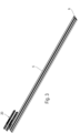
- the guide rail 5 is shown, on which a mounting part 9 or 10 is inserted on opposite sides.
- These mounting parts 9 and 10 serve to fix one or more self-closing devices 20 or stops 40, by means of which an end position of a sliding door 6 or 7 is specified.
- the mounting part 10 comprises a mounting web 11, on which a clamping element in the form of a slot nut 12 is held.
- a screw passes through the mounting web 11 and the slot nut 12 in order to clamp the mounting web 11 to the guide rail 5 after it has been pushed into a channel or groove.
- two webs 13 and 17 are provided on the mounting part 10, which can be inserted into corresponding grooves or channels of the guide rail 5.
- Two mounting elements 15 and 16 are formed on the web 13, which are arranged offset in the longitudinal direction of the guide rail 5, i.e. one behind the other.
- Two mounting elements 18 and 19 are also provided on the web 17, which are also arranged offset in the longitudinal direction of the guide rail 5.
- the mounting elements 15, 16, 18 and 19 are designed as pot-shaped receptacles, but can also be formed by webs, recesses or other shaped bodies.
- Both webs 13 and 17 are attached to a wall 14, which can be placed against the front of the guide rail 5.
- the webs 13 and 17 have a different height in relation to the top floor 3, but can also be arranged at the same height.
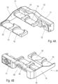
- FIG. 5A and 5B a further mounting part 9 is shown, which is fixed to the guide rail 5 on the opposite side to the mounting part 10.
- the mounting part 9 also comprises two webs 13 and 17, on which mounting elements 15, 16, 18 and 19 are provided.
- the mounting part 9 does not have a mounting web 11 with a clamping element, so that the mounting part 9 can only be loosely inserted into the guide rail 5.
- the mounting part 10 is fixedly arranged on the guide rail 5 via a force-fitting fixation, while the mounting part 9 is displaceable in the longitudinal direction of the guide rail 5.
- Each self-closing device 20 comprises an elongated housing 21 on which a guide track 22 for a driver 23 is formed.
- the guide track 22 can be linear with an angled end section on which the driver 23 can be pivoted and fixed in a parking position.
- the driver 23 is pre-tensioned via a force accumulator, in particular a spring, and can be braked into a retracted position by means of a damper device 24.
- Each driver 23 can be connected to one of the sliding doors 6 or 7 to move the sliding door 6 or 7 to an end position and hold it there.
- At least one clamping element in the form of a slot nut 25 is provided on the housing 21, which can be inserted into one of the mounting elements 15, 16, 18 or 19 and is then clamped to the guide rail 5 by turning.
- FIG. 6 further shows, for example, a self-closing mechanism 20 for the rear sliding door 6 can be positioned on a mounting element 18 on the web 17 adjacent to the wall 14, while another self-closing mechanism 20 for the front sliding door 7 is positioned on a mounting element 16 on the web 13 further away from the wall 14.
- the mounting elements 15 and 16 on the web 13 are each in alignment with the mounting elements 18 and 19 on the web 17.
- a stop 40 which can be mounted on one of the mounting parts 9 or 10 instead of a self-closing mechanism 20.
- Each stop 40 comprises a stop element 41 which, in the embodiment shown, is designed as a U-shaped holder in which a bolt or another component can be fixed in a locking manner in order to hold a sliding door 6 or 7 in an end position.
- the stop element 41 is held on a web 42 which has at least one clamping element in the form of a slot nut 43 at the end which, as previously described, can be fixed in a clamping manner on or in the guide rail 5 by turning after the desired positioning of the stop 40 to one of the mounting elements 15, 16, 18 or 19.
- the end position of the sliding door 6 or 7 is preset.
- the mounting elements 15 and 16 as well as 18 and 19 can, for example, have a distance of between 20 mm and 40 mm in order to preset a position of the sliding door in front of a front edge of a side wall 4 or next to the side wall 4. Fine adjustment of the The final position can then optionally be set using the running parts 60 and 70.
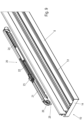
- the guide rail 5 comprises two tracks 51 and 52, each of which is formed on T-shaped webs. Other geometries for the tracks 51 and 52 are of course also possible.
- the two tracks 51 and 52 are each arranged between side walls 53, which protrude vertically upwards.
- a groove 54 is provided on the side of the guide rail 5, into which an area with the slot nut of the mounting web 11 can be inserted.
- the groove 54 is undercut with inwardly projecting webs that at least partially surround the mounting web 11. To fix the mounting part 10, the mounting web 11 is pushed into the groove 54 and then the screw with the slot nut 12 is turned from the outside until it hits the groove walls and is then clamped onto the guide rail 5.
- a groove 55 is formed into which the web 13 can be inserted.
- a groove 56 is formed on the guide rail 5, into which the web 17 is inserted.
- the self-closing device 20 ( Figure 9 ) or a stop 40 is inserted from above into the respective groove 55 or 56.
- the fitter can now choose whether to use the mounting element 15 or 18 adjacent to the wall 14 or the mounting element 16 or 19 further away from the wall 14 to fix the self-closing mechanism 20.
- Assembly is carried out in such a way that the housing 21 of the self-closing mechanism 20 is inserted into the groove 55 or 56 and is then pre-positioned on the mounting part 10 by the at least one sliding block 25 arranged on the underside of the housing 21 assuming the predetermined position in the mounting element 15, 16, 17 or 18.
- the fitter can then turn the at least one screw 26, which in a first step turns the sliding block 25 and secures it against lifting on the undercut groove 55 or 56.
- the at least one slot nut 25 is elongated and can only cover a certain angle range in the slot 55 or 56 until it hits the groove walls, so that by tightening the screw 26 the inwardly projecting webs on the groove 55 and 56 are clamped between the housing 21 and the at least one slot nut 25 and the self-closing mechanism 20 is thus fixed in the desired position.
- the second self-closing mechanism 20 or a stop 40 can now be fixed to the other groove 55 or 56.
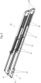
- a guide rail 5 is shown being mounted on a top panel 3, to which four holders 30 are already attached.
- the furniture body with the top panel 3 is only partially shown, and the guide rail 5 can extend between two side walls 4.
- a mounting part 10 is inserted into the end of the guide rail 5 and a further mounting part 9 is inserted into the opposite end.
- a large number of self-closing mechanisms 20 are already fixed to the guide rail 5 in order to hold at least one sliding door in a closed position or an open position or to hold two sliding doors at a distance from one another.
- Each holder 30 comprises a base 31 which is essentially plate-shaped and can be fixed to the top 3 via screws or other fastening means which pass through the base 31.
- a bearing receptacle 32 is formed on the base 31, into which a locking element 34 can be inserted, which is essentially bolt-shaped.
- the base 31 also has one or more hooks 33 which protrude on the side facing the guide rail 5.
- the locking element 34 is rotatable via an actuating element 35 designed as a lever, which protrudes radially.
- the locking element 34 also has a recess 36 into which a projection 38 of the base 31 engages in order to secure the locking element 34 in the axial direction on the base 31.
- the locking element 34 also has a flattened area 37 at one end, so that the end is not cylindrical, but has a recess on one side above the flattened area 37.
- FIGS 12A to 12C and 13A to 13C The mounting of the guide rail 5 with the self-closing devices 20 on a holder 30 is shown.
- the holder 30 is fixed to the top floor 3, and the guide rail 5 is accordingly Figure 12A or 13A parallel to the top floor with only one joining direction.
- a recess 39 is provided on the mounting web 11 of the mounting part 10, through which the hooks 33 and a front end of the locking element 34 can pass in order to engage in a groove 54 of the guide rail 5.
- the Figures 12B and 13B shown position is reached.
- the locking element 34 engages with a front end in the undercut groove 54, the hooks 33 engaging behind an upper web of the groove 54 and the flattening 37 pointing downwards so that the guide rail 5 can be easily lifted and removed in the unlocked position.
- the hooks 33 engage in the recess 39 of the mounting web 11 in such a way that one of their vertical side surfaces almost comes into contact with the respective outer lateral boundary surface of the recess 39 with only a small amount of play. In this way, movement in the longitudinal direction of the guide rail 5 can be effectively prevented.
- the locking element 34 is rotated via the actuating element 35 so that the flattening 37 is turned to the side and the locking element 34 comes to rest on the lower web of the groove 54.
- the guide rail 5 can no longer be lifted, since this is blocked by the locking element 34, as is particularly the case Figure 12C shows.
- the guide rail 5 is thus secured by a positive engagement between the base 31 and the mounting web 11 in the longitudinal direction of the guide rail 5, and in addition the guide rail 5 cannot be moved perpendicular to the longitudinal direction, since this is prevented by the engagement of the locking element 34 and the hook 33 in the groove 54.
- other profile webs can also be used to lock the guide rail 5 to a holder 30 in a direction perpendicular to the longitudinal direction of the guide rail 5.
- FIG 14 the guide rail 5 is shown in an assembled position.
- Four holders 30 are arranged distributed over the length of the guide rail 5, whereby only the holder 30 on the mounting part 10 fixes the guide rail 5 in its longitudinal direction. All holders 30, however, fix the guide rail 5 perpendicular to the longitudinal direction to prevent it from being lifted or moved in the horizontal direction.
- Several self-closing devices 20 are fixed to the guide rail 5 in the grooves 55, 56, as explained above. It is of course also possible to provide only stops 40 on the mounting elements 15, 16, 18 and 19 instead of the self-closing devices 20.
- a modified holder 30 for fixing a guide rail 5 is shown.
- the holder 30 comprises a plate-shaped base 31, which can be fixed to a floor or top floor 3 using screws or other fastening means.
- a locking element 34 is rotatably held on a bearing receptacle 32 of the base 31.
- two projections 46 protruding upwards relative to the base 31 are formed next to the hooks 33 for supporting the guide rail 5, the hooks 33 being designed analogously to the first embodiment.
- the locking element 34 can be arranged in the bearing receptacle 32 in a rotatable manner via a radially protruding actuating element 35 designed as a lever.
- a recess 36 is provided on the locking element 34, into which a projection 38 of the base 31 engages in order to secure the locking element 34 in the axial direction on the base 31.
- the locking element 34 also has a lateral flattening 37 at one end. In the area of the flattening 37, a Figure 18 recognizable helical curve guide 45 is arranged.
- the locking element 34 further has a resilient portion 44 which is formed by flexible webs on an otherwise bolt-shaped portion on the locking element 34.
- the mounting of the guide rail 5 on a holder 30 of the Figure 15 is in the Figures 16A and 16B shown.
- the locking element 34 is rotated via the actuating element 35 until the Figure 16B shown position is reached.
- the flattened portion 37 is rotated to the side and the locking element 34 holds the guide rail 5 essentially free of play in the vertical direction in order to prevent the guide rail 5 from being lifted.
- the guide rail 5 is also attracted by the curved guide 45 in the axial direction of the locking element 34 in the direction of the holder 30.
- the projections 46 act as torque support elements on a groove wall 58 of the groove 57, which is formed above the groove 54.
- the resilient section 44 can carry out a certain compensating movement in the axial direction. This possible compensating movement can be used in particular to compensate for tolerances in the fastening system in order to avoid undesirable tensions in the guide rail 5.
- Figure 17 the holder 30 with the locking element 34 is shown in a top view without the guide rail 5.
- the helical curved guide 45 designed in a spiral shape can be seen, which, as previously described, is able to move and brace a web projecting inwards into the curved guide in the axial direction when the locking element 34 is rotated.
- the Figure 18 shows the locking element 34 without the base 31.
- the resilient portion 44 comprises a plurality of flexible webs arranged in a grid shape, which can execute a compensating movement in the axial direction of the bolt-shaped locking element 34.
- a spring element such as a compression spring or a disc spring can perform the same task.
Landscapes
- Engineering & Computer Science (AREA)
- Mechanical Engineering (AREA)
- Support Devices For Sliding Doors (AREA)
Claims (16)
- Dispositif de guidage pour une porte coulissante (6, 7), avec un rail de guidage (5) qui présente au moins une voie de roulement (51, 52) pour une pièce de roulement (60, 70) déplaçable, une pièce de montage (9, 10), et une butée (40) et/ou un retour automatique (20) est monté sur chaque pièce de montage (9, 10), au moins une pièce de montage (9, 10) pouvant être fixée sur un plancher supérieur (3) ou sur le sol par l'intermédiaire d'un support (30) du dispositif de guidage, un premier support (30) fixant, en position montée, l'une des pièces de montage (10) dans la direction longitudinale du rail de guidage (5) et perpendiculairement à celle-ci, et un deuxième support (30) du dispositif de guidage fixant le rail de guidage (5) ou l'autre pièce de montage (9) perpendiculairement à la direction longitudinale du rail de guidage (5) et le maintenant mobile dans la direction longitudinale du rail de guidage (5), caractérisé en ce que la butée (40) ou le retour automatique (20) est fixé à une rainure (55, 56) du rail de guidage (5) par l'intermédiaire d'au moins un coulisseau (25, 43).
- Dispositif de guidage selon la revendication 1, caractérisé en ce que le premier support (30) fixe, dans la position de montage, l'une des pièces de montage (10) dans la direction longitudinale du rail de guidage (5) et, perpendiculairement à celle-ci, parallèlement au plancher supérieur (3) ou au sol.
- Dispositif de guidage selon la revendication 1 ou 2, caractérisé en ce que les supports (30) présentent un élément de verrouillage (34) pour fixer les pièces de montage (9, 10) et/ou le rail de guidage (5).
- Dispositif de guidage selon la revendication 3, caractérisé en ce que l'élément de verrouillage (34) peut être actionné par un élément d'actionnement (35) du support respectif.
- Dispositif de guidage selon la revendication 3, caractérisé en ce que chaque support (30) présente une base (31) pouvant être fixée sur un sol ou un plancher supérieur (3) et l'élément de verrouillage (34) pouvant être déplacé par l'intermédiaire de l'élément d'actionnement (35), qui peut être fixé par une section d'extrémité sur une âme ou dans une rainure du (54) rail de guidage (5).
- Dispositif de guidage selon la revendication 5, caractérisé en ce que la base (31) peut s'engager avec au moins un crochet (33) dans l'autre rainure (54) du rail de guidage (5) réalisée sous la forme d'une rainure en contre-dépouille, et l'élément de verrouillage (34) peut, dans une position de verrouillage, bloquer le au moins un crochet (33) dans l'autre rainure (54).
- Dispositif de guidage selon la revendication 5, caractérisé en ce que sur chaque support (30) est formée au moins une saillie (46) faisant saillie vers le haut par rapport à la base (31), qui peut s'appuyer sur une section de paroi verticale et/ou une section de paroi horizontale du rail de guidage (5).
- Dispositif de guidage selon la revendication 5 ou 6, caractérisé en ce que l'élément de verrouillage (34) présente un guidage à came (45) au moyen duquel le rail de guidage (5) peut être fixé par serrage lors d'un pivotement ou d'un déplacement de l'élément de verrouillage (34).
- Dispositif de guidage selon l'une quelconque des revendications précédentes 3 à 8, caractérisé en ce que l'élément de verrouillage (34) coopère avec au moins un élément élastique ou au moins une partie élastique (44) est formée d'un seul tenant sur celui-ci.
- Dispositif de guidage selon l'une des revendications précédentes, caractérisé en ce que, dans la position de montage, l'une des pièces de montage (10) avec la fixation dans la direction longitudinale du rail de guidage (5) présente une nervure de montage (11) s'étendant dans la direction longitudinale, qui est en prise par complémentarité de forme avec le premier support (30).
- Dispositif de guidage selon l'une des revendications précédentes, caractérisé en ce que chaque pièce de montage (9, 10) présente au moins un élément de montage (15, 16, 18, 19) pour la fixation de la butée (40) ou du retour automatique (20) et les éléments de montage (15, 16, 18, 19) sont disposés sur des entretoises (13, 17) des pièces de montage qui sont insérées dans le rail de guidage (5).
- Dispositif de guidage selon la revendication 11, caractérisé en ce que les éléments de montage (15, 16, 18, 19) sont réalisés sous forme de logements dans lesquels un élément de serrage de la butée (40) ou de la fermeture automatique peut être inséré pour fixer la butée (40) ou le retour automatique (20).
- Dispositif de guidage selon l'une des revendications précédentes 11 ou 12, caractérisé en ce que chaque pièce de montage (9, 10) présente une section de paroi (14) qui est appliquée frontalement contre le rail de guidage (5), une rainure (55, 56) du rail de guidage (5) destinée à recevoir au moins un élément de montage (15, 16, 18, 19) étant disposée au voisinage d'une voie de roulement (51, 52) sur le rail de guidage (5).
- Procédé de montage d'un rail de guidage (5) d'un dispositif de guidage pour une porte coulissante (6, 7), comprenant les étapes suivantes :- Fixation de plusieurs supports (30) sur un fond au un plancher supérieur (3) d'un meuble de rangement (1) ;- l'insertion d'une première pièce de montage (10) sur une face frontale du rail de guidage (5) ;- l'insertion d'une deuxième pièce de montage (9) sur une face frontale opposée du rail de guidage (5) ;- Positionner le rail de guidage (5) sur les supports (30) ;- fixer la première pièce de montage (10) sur le rail de guidage (5), et- le verrouillage des supports (30) de telle sorte que le rail de guidage (5) soit fixé sur la première pièce de montage (10) dans la direction longitudinale et perpendiculairement à la direction longitudinale du rail de guidage (5) et que sur l'autre support (30) ne s'effectue qu'une fixation perpendiculaire à la direction longitudinale du rail de guidage (5)- caractérisé en ce qu'une butée (40) ou un retour automatique (20) est fixé sur une rainure (55, 56) du rail de guidage (5) par l'intermédiaire d'au moins un coulisseau (25, 43).
- Procédé selon la revendication 14, caractérisé en ce que les supports (30) présentent chacun un élément de verrouillage (34) qui s'engage par une extrémité dans une autre rainure (54) du rail de guidage (5).
- Procédé selon la revendication 14 ou 15, caractérisé en ce qu'au moins deux supports (30) sont montés en étant répartis sur le rail de guidage (5).
Applications Claiming Priority (2)
| Application Number | Priority Date | Filing Date | Title |
|---|---|---|---|
| DE102018112026.5A DE102018112026A1 (de) | 2018-05-18 | 2018-05-18 | Führungsvorrichtung für eine Schiebetür und Verfahren zur Montage einer Führungsschiene |
| PCT/EP2019/062803 WO2019219910A1 (fr) | 2018-05-18 | 2019-05-17 | Dispositif de guidage pour une porte coulissante et procédé de montage d'un rail de guidage |
Publications (2)
| Publication Number | Publication Date |
|---|---|
| EP3794193A1 EP3794193A1 (fr) | 2021-03-24 |
| EP3794193B1 true EP3794193B1 (fr) | 2024-12-25 |
Family
ID=66597609
Family Applications (1)
| Application Number | Title | Priority Date | Filing Date |
|---|---|---|---|
| EP19725145.7A Active EP3794193B1 (fr) | 2018-05-18 | 2019-05-17 | Dispositif de guidage pour une porte coulissante et procédé de montage d'un rail de guidage |
Country Status (4)
| Country | Link |
|---|---|
| EP (1) | EP3794193B1 (fr) |
| CN (1) | CN112166234B (fr) |
| DE (1) | DE102018112026A1 (fr) |
| WO (1) | WO2019219910A1 (fr) |
Families Citing this family (2)
| Publication number | Priority date | Publication date | Assignee | Title |
|---|---|---|---|---|
| IT201700008876A1 (it) * | 2017-01-27 | 2018-07-27 | Terno Scorrevoli S P A Unipersonale | Dispositivo per lo scorrimento e la frenatura di porte scorrevoli e ante |
| IT202200007370A1 (it) | 2022-04-13 | 2023-10-13 | Terno Scorrevoli S P A Unipersonale | Dispositivo per l’aggancio e la regolazione di accessori lungo profili di supporto |
Family Cites Families (10)
| Publication number | Priority date | Publication date | Assignee | Title |
|---|---|---|---|---|
| GB2407965A (en) * | 2003-11-14 | 2005-05-18 | Cairns Michael Paul | Curtain pole hanging bracket and system |
| ITMI20072168A1 (it) * | 2007-11-14 | 2009-05-15 | Agostino Ferrari Spa | "sistema di chiusura controllata per elementi scorrevoli di mobilio" |
| IT1392935B1 (it) | 2009-02-23 | 2012-04-02 | Caimi Export Spa | Dispositivo per la movimentazione di ante scorrevoli |
| IT1401802B1 (it) * | 2010-10-19 | 2013-08-28 | Bortoluzzi Lab S R L | Sistema di fissaggio a scatto delle guide, particolarmente per porte scorrevoli di mobili |
| JP6082590B2 (ja) * | 2012-12-26 | 2017-02-15 | 磯川産業株式会社 | 引戸用ランナー構造 |
| CN203503951U (zh) * | 2013-10-25 | 2014-03-26 | 深圳市奥普利斯光电有限公司 | 可滑动的调光膜导电装置 |
| DE102014109429B4 (de) * | 2014-07-07 | 2026-01-22 | Hettich-Heinze Gmbh & Co. Kg | Beschlag für eine Schiebetür |
| DE102014114339A1 (de) * | 2014-10-02 | 2016-04-07 | Hettich-Heinze Gmbh & Co. Kg | Führungseinrichtung zur Führung einer Schiebetür und Schrankmöbel |
| DE102015114392A1 (de) * | 2015-08-28 | 2017-03-02 | Hettich-Heinze Gmbh & Co. Kg | Vorrichtung zum Positionieren von zwei Schiebetüren und Möbel |
| EP3592929B1 (fr) * | 2017-03-08 | 2021-02-17 | Hettich-Heinze GmbH & Co. KG | Unité de montage et procédé de montage d'un rail de guidage sur un panneau supérieur ou un panneau inférieur d'un meuble |
-
2018
- 2018-05-18 DE DE102018112026.5A patent/DE102018112026A1/de active Pending
-
2019
- 2019-05-17 CN CN201980032653.9A patent/CN112166234B/zh active Active
- 2019-05-17 WO PCT/EP2019/062803 patent/WO2019219910A1/fr not_active Ceased
- 2019-05-17 EP EP19725145.7A patent/EP3794193B1/fr active Active
Also Published As
| Publication number | Publication date |
|---|---|
| CN112166234A (zh) | 2021-01-01 |
| DE102018112026A1 (de) | 2019-11-21 |
| CN112166234B (zh) | 2022-09-02 |
| EP3794193A1 (fr) | 2021-03-24 |
| WO2019219910A1 (fr) | 2019-11-21 |
Similar Documents
| Publication | Publication Date | Title |
|---|---|---|
| DE202018102084U1 (de) | Vorrichtung zur Bewegung eines an einem Möbelkorpus eines Möbels aufgenommenen Möbelteils | |
| EP1916361A1 (fr) | Poignée prevue pour être montée dans une ouverture | |
| EP3713448B1 (fr) | Dispositif de fixation d'un tiroir et meuble | |
| EP0940067A2 (fr) | Armoire de distribution comportant une plaque de montage | |
| EP3105397A1 (fr) | Ferrure de porte pouclisante | |
| EP3794193B1 (fr) | Dispositif de guidage pour une porte coulissante et procédé de montage d'un rail de guidage | |
| EP3859110B1 (fr) | Ferrure de porte coulissante et procédé de déplacement d'un dispositif de commande | |
| EP3859107B1 (fr) | Porte coulissante | |
| WO2012110373A1 (fr) | Dispositif servant à verrouiller des pièces mobiles l'une par rapport à l'autre | |
| EP3742931B1 (fr) | Glissière de guidage pour un tiroir et procédé pour aligner un tiroir à une glissière de guidage | |
| EP3954852B1 (fr) | Dispositif de guidage et meuble | |
| EP3859105B1 (fr) | Dispositif de fermeture | |
| EP1716778B1 (fr) | Tiroir pour un corps isolé étant bilatéralement extensible | |
| EP3569804B1 (fr) | Dispositif de guidage pour une porte coulissante | |
| EP3464767B1 (fr) | Système de guidage avec un élément coulissant, meuble et procédure pour le montage d'un tel élément sur le meuble | |
| WO2024016032A1 (fr) | Paroi latérale de tiroir | |
| EP1775482A1 (fr) | Elément de fixation rapide | |
| EP4263990A1 (fr) | Dispositif de montage pour supporter au moins un battant de porte | |
| EP0063294B1 (fr) | Dispositif de fixation, en particulier pour accoudoir ou poignées à la paroi intérieure de carosserie pour véhicules | |
| DE69002342T2 (de) | Befestigungsvorrichtung durch Zusammenschrauben auf einem Profil, insbesondere auf einem Elektrizitätsschrank. | |
| EP4184731B1 (fr) | Elément de montage pour l'aménagement intérieur d'un boîtier d'armoire électrique et agencement d'armoire électrique correspondant | |
| DE10319955B4 (de) | Verstelleinrichtung | |
| WO2018210901A1 (fr) | Meuble et procédé de montage d'un élément coulissant sur un corps de meuble | |
| EP3256677B1 (fr) | Ferrure destinée à au moins un battant mobile linéairement et meuble | |
| DE8111051U1 (de) | Armlehne o.dgl., insbesondere für Fahrzeuge |
Legal Events
| Date | Code | Title | Description |
|---|---|---|---|
| STAA | Information on the status of an ep patent application or granted ep patent |
Free format text: STATUS: UNKNOWN |
|
| STAA | Information on the status of an ep patent application or granted ep patent |
Free format text: STATUS: THE INTERNATIONAL PUBLICATION HAS BEEN MADE |
|
| PUAI | Public reference made under article 153(3) epc to a published international application that has entered the european phase |
Free format text: ORIGINAL CODE: 0009012 |
|
| STAA | Information on the status of an ep patent application or granted ep patent |
Free format text: STATUS: REQUEST FOR EXAMINATION WAS MADE |
|
| 17P | Request for examination filed |
Effective date: 20201126 |
|
| AK | Designated contracting states |
Kind code of ref document: A1 Designated state(s): AL AT BE BG CH CY CZ DE DK EE ES FI FR GB GR HR HU IE IS IT LI LT LU LV MC MK MT NL NO PL PT RO RS SE SI SK SM TR |
|
| AX | Request for extension of the european patent |
Extension state: BA ME |
|
| DAV | Request for validation of the european patent (deleted) | ||
| DAX | Request for extension of the european patent (deleted) | ||
| GRAP | Despatch of communication of intention to grant a patent |
Free format text: ORIGINAL CODE: EPIDOSNIGR1 |
|
| STAA | Information on the status of an ep patent application or granted ep patent |
Free format text: STATUS: GRANT OF PATENT IS INTENDED |
|
| INTG | Intention to grant announced |
Effective date: 20240807 |
|
| GRAS | Grant fee paid |
Free format text: ORIGINAL CODE: EPIDOSNIGR3 |
|
| GRAA | (expected) grant |
Free format text: ORIGINAL CODE: 0009210 |
|
| STAA | Information on the status of an ep patent application or granted ep patent |
Free format text: STATUS: THE PATENT HAS BEEN GRANTED |
|
| AK | Designated contracting states |
Kind code of ref document: B1 Designated state(s): AL AT BE BG CH CY CZ DE DK EE ES FI FR GB GR HR HU IE IS IT LI LT LU LV MC MK MT NL NO PL PT RO RS SE SI SK SM TR |
|
| P01 | Opt-out of the competence of the unified patent court (upc) registered |
Free format text: CASE NUMBER: APP_61609/2024 Effective date: 20241118 |
|
| REG | Reference to a national code |
Ref country code: GB Ref legal event code: FG4D Free format text: NOT ENGLISH |
|
| REG | Reference to a national code |
Ref country code: CH Ref legal event code: EP |
|
| REG | Reference to a national code |
Ref country code: DE Ref legal event code: R096 Ref document number: 502019012691 Country of ref document: DE |
|
| REG | Reference to a national code |
Ref country code: IE Ref legal event code: FG4D Free format text: LANGUAGE OF EP DOCUMENT: GERMAN |
|
| REG | Reference to a national code |
Ref country code: LT Ref legal event code: MG9D |
|
| PG25 | Lapsed in a contracting state [announced via postgrant information from national office to epo] |
Ref country code: FI Free format text: LAPSE BECAUSE OF FAILURE TO SUBMIT A TRANSLATION OF THE DESCRIPTION OR TO PAY THE FEE WITHIN THE PRESCRIBED TIME-LIMIT Effective date: 20241225 |
|
| PG25 | Lapsed in a contracting state [announced via postgrant information from national office to epo] |
Ref country code: BG Free format text: LAPSE BECAUSE OF FAILURE TO SUBMIT A TRANSLATION OF THE DESCRIPTION OR TO PAY THE FEE WITHIN THE PRESCRIBED TIME-LIMIT Effective date: 20241225 |
|
| PG25 | Lapsed in a contracting state [announced via postgrant information from national office to epo] |
Ref country code: NO Free format text: LAPSE BECAUSE OF FAILURE TO SUBMIT A TRANSLATION OF THE DESCRIPTION OR TO PAY THE FEE WITHIN THE PRESCRIBED TIME-LIMIT Effective date: 20250325 |
|
| PG25 | Lapsed in a contracting state [announced via postgrant information from national office to epo] |
Ref country code: LV Free format text: LAPSE BECAUSE OF FAILURE TO SUBMIT A TRANSLATION OF THE DESCRIPTION OR TO PAY THE FEE WITHIN THE PRESCRIBED TIME-LIMIT Effective date: 20241225 Ref country code: GR Free format text: LAPSE BECAUSE OF FAILURE TO SUBMIT A TRANSLATION OF THE DESCRIPTION OR TO PAY THE FEE WITHIN THE PRESCRIBED TIME-LIMIT Effective date: 20250326 |
|
| PG25 | Lapsed in a contracting state [announced via postgrant information from national office to epo] |
Ref country code: RS Free format text: LAPSE BECAUSE OF FAILURE TO SUBMIT A TRANSLATION OF THE DESCRIPTION OR TO PAY THE FEE WITHIN THE PRESCRIBED TIME-LIMIT Effective date: 20250325 |
|
| REG | Reference to a national code |
Ref country code: NL Ref legal event code: MP Effective date: 20241225 |
|
| PG25 | Lapsed in a contracting state [announced via postgrant information from national office to epo] |
Ref country code: NL Free format text: LAPSE BECAUSE OF FAILURE TO SUBMIT A TRANSLATION OF THE DESCRIPTION OR TO PAY THE FEE WITHIN THE PRESCRIBED TIME-LIMIT Effective date: 20241225 |
|
| PG25 | Lapsed in a contracting state [announced via postgrant information from national office to epo] |
Ref country code: SM Free format text: LAPSE BECAUSE OF FAILURE TO SUBMIT A TRANSLATION OF THE DESCRIPTION OR TO PAY THE FEE WITHIN THE PRESCRIBED TIME-LIMIT Effective date: 20241225 |
|
| PG25 | Lapsed in a contracting state [announced via postgrant information from national office to epo] |
Ref country code: PL Free format text: LAPSE BECAUSE OF FAILURE TO SUBMIT A TRANSLATION OF THE DESCRIPTION OR TO PAY THE FEE WITHIN THE PRESCRIBED TIME-LIMIT Effective date: 20241225 |
|
| PGFP | Annual fee paid to national office [announced via postgrant information from national office to epo] |
Ref country code: DE Payment date: 20250519 Year of fee payment: 7 |
|
| PG25 | Lapsed in a contracting state [announced via postgrant information from national office to epo] |
Ref country code: ES Free format text: LAPSE BECAUSE OF FAILURE TO SUBMIT A TRANSLATION OF THE DESCRIPTION OR TO PAY THE FEE WITHIN THE PRESCRIBED TIME-LIMIT Effective date: 20241225 |
|
| PG25 | Lapsed in a contracting state [announced via postgrant information from national office to epo] |
Ref country code: IS Free format text: LAPSE BECAUSE OF FAILURE TO SUBMIT A TRANSLATION OF THE DESCRIPTION OR TO PAY THE FEE WITHIN THE PRESCRIBED TIME-LIMIT Effective date: 20250425 |
|
| PGFP | Annual fee paid to national office [announced via postgrant information from national office to epo] |
Ref country code: IT Payment date: 20250530 Year of fee payment: 7 |
|
| PG25 | Lapsed in a contracting state [announced via postgrant information from national office to epo] |
Ref country code: PT Free format text: LAPSE BECAUSE OF FAILURE TO SUBMIT A TRANSLATION OF THE DESCRIPTION OR TO PAY THE FEE WITHIN THE PRESCRIBED TIME-LIMIT Effective date: 20250428 |
|
| PG25 | Lapsed in a contracting state [announced via postgrant information from national office to epo] |
Ref country code: EE Free format text: LAPSE BECAUSE OF FAILURE TO SUBMIT A TRANSLATION OF THE DESCRIPTION OR TO PAY THE FEE WITHIN THE PRESCRIBED TIME-LIMIT Effective date: 20241225 |
|
| PGFP | Annual fee paid to national office [announced via postgrant information from national office to epo] |
Ref country code: CH Payment date: 20250601 Year of fee payment: 7 |
|
| PG25 | Lapsed in a contracting state [announced via postgrant information from national office to epo] |
Ref country code: RO Free format text: LAPSE BECAUSE OF FAILURE TO SUBMIT A TRANSLATION OF THE DESCRIPTION OR TO PAY THE FEE WITHIN THE PRESCRIBED TIME-LIMIT Effective date: 20241225 |
|
| PG25 | Lapsed in a contracting state [announced via postgrant information from national office to epo] |
Ref country code: SK Free format text: LAPSE BECAUSE OF FAILURE TO SUBMIT A TRANSLATION OF THE DESCRIPTION OR TO PAY THE FEE WITHIN THE PRESCRIBED TIME-LIMIT Effective date: 20241225 |
|
| PG25 | Lapsed in a contracting state [announced via postgrant information from national office to epo] |
Ref country code: CZ Free format text: LAPSE BECAUSE OF FAILURE TO SUBMIT A TRANSLATION OF THE DESCRIPTION OR TO PAY THE FEE WITHIN THE PRESCRIBED TIME-LIMIT Effective date: 20241225 |
|
| PG25 | Lapsed in a contracting state [announced via postgrant information from national office to epo] |
Ref country code: SE Free format text: LAPSE BECAUSE OF FAILURE TO SUBMIT A TRANSLATION OF THE DESCRIPTION OR TO PAY THE FEE WITHIN THE PRESCRIBED TIME-LIMIT Effective date: 20241225 |
|
| REG | Reference to a national code |
Ref country code: DE Ref legal event code: R097 Ref document number: 502019012691 Country of ref document: DE |
|
| PG25 | Lapsed in a contracting state [announced via postgrant information from national office to epo] |
Ref country code: DK Free format text: LAPSE BECAUSE OF FAILURE TO SUBMIT A TRANSLATION OF THE DESCRIPTION OR TO PAY THE FEE WITHIN THE PRESCRIBED TIME-LIMIT Effective date: 20241225 |
|
| PLBE | No opposition filed within time limit |
Free format text: ORIGINAL CODE: 0009261 |
|
| STAA | Information on the status of an ep patent application or granted ep patent |
Free format text: STATUS: NO OPPOSITION FILED WITHIN TIME LIMIT |
|
| 26N | No opposition filed |
Effective date: 20250926 |
|
| PG25 | Lapsed in a contracting state [announced via postgrant information from national office to epo] |
Ref country code: LU Free format text: LAPSE BECAUSE OF NON-PAYMENT OF DUE FEES Effective date: 20250517 |
|
| GBPC | Gb: european patent ceased through non-payment of renewal fee |
Effective date: 20250517 |
|
| REG | Reference to a national code |
Ref country code: BE Ref legal event code: MM Effective date: 20250531 |
|
| PG25 | Lapsed in a contracting state [announced via postgrant information from national office to epo] |
Ref country code: MC Free format text: LAPSE BECAUSE OF FAILURE TO SUBMIT A TRANSLATION OF THE DESCRIPTION OR TO PAY THE FEE WITHIN THE PRESCRIBED TIME-LIMIT Effective date: 20241225 |
|
| PG25 | Lapsed in a contracting state [announced via postgrant information from national office to epo] |
Ref country code: GB Free format text: LAPSE BECAUSE OF NON-PAYMENT OF DUE FEES Effective date: 20250517 |
|
| PG25 | Lapsed in a contracting state [announced via postgrant information from national office to epo] |
Ref country code: IE Free format text: LAPSE BECAUSE OF NON-PAYMENT OF DUE FEES Effective date: 20250517 |
|
| PG25 | Lapsed in a contracting state [announced via postgrant information from national office to epo] |
Ref country code: HR Free format text: LAPSE BECAUSE OF FAILURE TO SUBMIT A TRANSLATION OF THE DESCRIPTION OR TO PAY THE FEE WITHIN THE PRESCRIBED TIME-LIMIT Effective date: 20241225 |
|
| PG25 | Lapsed in a contracting state [announced via postgrant information from national office to epo] |
Ref country code: BE Free format text: LAPSE BECAUSE OF NON-PAYMENT OF DUE FEES Effective date: 20250531 |
|
| PG25 | Lapsed in a contracting state [announced via postgrant information from national office to epo] |
Ref country code: FR Free format text: LAPSE BECAUSE OF NON-PAYMENT OF DUE FEES Effective date: 20250531 |