EP3794665B1 - Wiederaufladbare batteriezelle - Google Patents
Wiederaufladbare batteriezelle Download PDFInfo
- Publication number
- EP3794665B1 EP3794665B1 EP20746666.5A EP20746666A EP3794665B1 EP 3794665 B1 EP3794665 B1 EP 3794665B1 EP 20746666 A EP20746666 A EP 20746666A EP 3794665 B1 EP3794665 B1 EP 3794665B1
- Authority
- EP
- European Patent Office
- Prior art keywords
- rechargeable battery
- battery cell
- electrolyte
- metal
- lithium
- Prior art date
- Legal status (The legal status is an assumption and is not a legal conclusion. Google has not performed a legal analysis and makes no representation as to the accuracy of the status listed.)
- Active
Links
Images


Classifications
-
- H—ELECTRICITY
- H01—ELECTRIC ELEMENTS
- H01M—PROCESSES OR MEANS, e.g. BATTERIES, FOR THE DIRECT CONVERSION OF CHEMICAL ENERGY INTO ELECTRICAL ENERGY
- H01M10/00—Secondary cells; Manufacture thereof
- H01M10/05—Accumulators with non-aqueous electrolyte
- H01M10/056—Accumulators with non-aqueous electrolyte characterised by the materials used as electrolytes, e.g. mixed inorganic/organic electrolytes
- H01M10/0561—Accumulators with non-aqueous electrolyte characterised by the materials used as electrolytes, e.g. mixed inorganic/organic electrolytes the electrolyte being constituted of inorganic materials only
- H01M10/0563—Liquid materials, e.g. for Li-SOCl2 cells
-
- H—ELECTRICITY
- H01—ELECTRIC ELEMENTS
- H01M—PROCESSES OR MEANS, e.g. BATTERIES, FOR THE DIRECT CONVERSION OF CHEMICAL ENERGY INTO ELECTRICAL ENERGY
- H01M4/00—Electrodes
- H01M4/02—Electrodes composed of, or comprising, active material
- H01M4/36—Selection of substances as active materials, active masses, active liquids
- H01M4/362—Composites
-
- C—CHEMISTRY; METALLURGY
- C01—INORGANIC CHEMISTRY
- C01G—COMPOUNDS CONTAINING METALS NOT COVERED BY SUBCLASSES C01D OR C01F
- C01G49/00—Compounds of iron
- C01G49/009—Compounds containing iron, with or without oxygen or hydrogen, and containing two or more other elements
-
- C—CHEMISTRY; METALLURGY
- C01—INORGANIC CHEMISTRY
- C01G—COMPOUNDS CONTAINING METALS NOT COVERED BY SUBCLASSES C01D OR C01F
- C01G51/00—Compounds of cobalt
- C01G51/40—Complex oxides containing cobalt and at least one other metal element
- C01G51/42—Complex oxides containing cobalt and at least one other metal element containing alkali metals, e.g. LiCoO2
-
- C—CHEMISTRY; METALLURGY
- C01—INORGANIC CHEMISTRY
- C01G—COMPOUNDS CONTAINING METALS NOT COVERED BY SUBCLASSES C01D OR C01F
- C01G53/00—Compounds of nickel
- C01G53/40—Complex oxides containing nickel and at least one other metal element
- C01G53/42—Complex oxides containing nickel and at least one other metal element containing alkali metals, e.g. LiNiO2
- C01G53/44—Complex oxides containing nickel and at least one other metal element containing alkali metals, e.g. LiNiO2 containing manganese
- C01G53/50—Complex oxides containing nickel and at least one other metal element containing alkali metals, e.g. LiNiO2 containing manganese of the type (MnO2)n-, e.g. Li(NixMn1-x)O2 or Li(MyNixMn1-x-y)O2
-
- C—CHEMISTRY; METALLURGY
- C01—INORGANIC CHEMISTRY
- C01G—COMPOUNDS CONTAINING METALS NOT COVERED BY SUBCLASSES C01D OR C01F
- C01G53/00—Compounds of nickel
- C01G53/40—Complex oxides containing nickel and at least one other metal element
- C01G53/42—Complex oxides containing nickel and at least one other metal element containing alkali metals, e.g. LiNiO2
- C01G53/44—Complex oxides containing nickel and at least one other metal element containing alkali metals, e.g. LiNiO2 containing manganese
- C01G53/54—Complex oxides containing nickel and at least one other metal element containing alkali metals, e.g. LiNiO2 containing manganese of the type (Mn2O4)-, e.g. Li(NixMn2-x)O4 or Li(MyNixMn2-x-y)O4
-
- C—CHEMISTRY; METALLURGY
- C07—ORGANIC CHEMISTRY
- C07F—ACYCLIC, CARBOCYCLIC OR HETEROCYCLIC COMPOUNDS CONTAINING ELEMENTS OTHER THAN CARBON, HYDROGEN, HALOGEN, OXYGEN, NITROGEN, SULFUR, SELENIUM OR TELLURIUM
- C07F5/00—Compounds containing elements of Groups 3 or 13 of the Periodic Table
- C07F5/02—Boron compounds
- C07F5/04—Esters of boric acids
-
- C—CHEMISTRY; METALLURGY
- C07—ORGANIC CHEMISTRY
- C07F—ACYCLIC, CARBOCYCLIC OR HETEROCYCLIC COMPOUNDS CONTAINING ELEMENTS OTHER THAN CARBON, HYDROGEN, HALOGEN, OXYGEN, NITROGEN, SULFUR, SELENIUM OR TELLURIUM
- C07F5/00—Compounds containing elements of Groups 3 or 13 of the Periodic Table
- C07F5/06—Aluminium compounds
- C07F5/069—Aluminium compounds without C-aluminium linkages
-
- H—ELECTRICITY
- H01—ELECTRIC ELEMENTS
- H01M—PROCESSES OR MEANS, e.g. BATTERIES, FOR THE DIRECT CONVERSION OF CHEMICAL ENERGY INTO ELECTRICAL ENERGY
- H01M10/00—Secondary cells; Manufacture thereof
- H01M10/05—Accumulators with non-aqueous electrolyte
- H01M10/052—Li-accumulators
-
- H—ELECTRICITY
- H01—ELECTRIC ELEMENTS
- H01M—PROCESSES OR MEANS, e.g. BATTERIES, FOR THE DIRECT CONVERSION OF CHEMICAL ENERGY INTO ELECTRICAL ENERGY
- H01M10/00—Secondary cells; Manufacture thereof
- H01M10/05—Accumulators with non-aqueous electrolyte
- H01M10/052—Li-accumulators
- H01M10/0525—Rocking-chair batteries, i.e. batteries with lithium insertion or intercalation in both electrodes; Lithium-ion batteries
-
- H—ELECTRICITY
- H01—ELECTRIC ELEMENTS
- H01M—PROCESSES OR MEANS, e.g. BATTERIES, FOR THE DIRECT CONVERSION OF CHEMICAL ENERGY INTO ELECTRICAL ENERGY
- H01M10/00—Secondary cells; Manufacture thereof
- H01M10/05—Accumulators with non-aqueous electrolyte
- H01M10/054—Accumulators with insertion or intercalation of metals other than lithium, e.g. with magnesium or aluminium
-
- H—ELECTRICITY
- H01—ELECTRIC ELEMENTS
- H01M—PROCESSES OR MEANS, e.g. BATTERIES, FOR THE DIRECT CONVERSION OF CHEMICAL ENERGY INTO ELECTRICAL ENERGY
- H01M10/00—Secondary cells; Manufacture thereof
- H01M10/05—Accumulators with non-aqueous electrolyte
- H01M10/056—Accumulators with non-aqueous electrolyte characterised by the materials used as electrolytes, e.g. mixed inorganic/organic electrolytes
- H01M10/0561—Accumulators with non-aqueous electrolyte characterised by the materials used as electrolytes, e.g. mixed inorganic/organic electrolytes the electrolyte being constituted of inorganic materials only
- H01M10/0562—Solid materials
-
- H—ELECTRICITY
- H01—ELECTRIC ELEMENTS
- H01M—PROCESSES OR MEANS, e.g. BATTERIES, FOR THE DIRECT CONVERSION OF CHEMICAL ENERGY INTO ELECTRICAL ENERGY
- H01M10/00—Secondary cells; Manufacture thereof
- H01M10/05—Accumulators with non-aqueous electrolyte
- H01M10/056—Accumulators with non-aqueous electrolyte characterised by the materials used as electrolytes, e.g. mixed inorganic/organic electrolytes
- H01M10/0564—Accumulators with non-aqueous electrolyte characterised by the materials used as electrolytes, e.g. mixed inorganic/organic electrolytes the electrolyte being constituted of organic materials only
- H01M10/0566—Liquid materials
- H01M10/0567—Liquid materials characterised by the additives
-
- H—ELECTRICITY
- H01—ELECTRIC ELEMENTS
- H01M—PROCESSES OR MEANS, e.g. BATTERIES, FOR THE DIRECT CONVERSION OF CHEMICAL ENERGY INTO ELECTRICAL ENERGY
- H01M10/00—Secondary cells; Manufacture thereof
- H01M10/05—Accumulators with non-aqueous electrolyte
- H01M10/056—Accumulators with non-aqueous electrolyte characterised by the materials used as electrolytes, e.g. mixed inorganic/organic electrolytes
- H01M10/0564—Accumulators with non-aqueous electrolyte characterised by the materials used as electrolytes, e.g. mixed inorganic/organic electrolytes the electrolyte being constituted of organic materials only
- H01M10/0566—Liquid materials
- H01M10/0568—Liquid materials characterised by the solutes
-
- H—ELECTRICITY
- H01—ELECTRIC ELEMENTS
- H01M—PROCESSES OR MEANS, e.g. BATTERIES, FOR THE DIRECT CONVERSION OF CHEMICAL ENERGY INTO ELECTRICAL ENERGY
- H01M10/00—Secondary cells; Manufacture thereof
- H01M10/42—Methods or arrangements for servicing or maintenance of secondary cells or secondary half-cells
- H01M10/4235—Safety or regulating additives or arrangements in electrodes, separators or electrolyte
-
- H—ELECTRICITY
- H01—ELECTRIC ELEMENTS
- H01M—PROCESSES OR MEANS, e.g. BATTERIES, FOR THE DIRECT CONVERSION OF CHEMICAL ENERGY INTO ELECTRICAL ENERGY
- H01M4/00—Electrodes
- H01M4/02—Electrodes composed of, or comprising, active material
- H01M4/13—Electrodes for accumulators with non-aqueous electrolyte, e.g. for lithium-accumulators; Processes of manufacture thereof
- H01M4/131—Electrodes based on mixed oxides or hydroxides, or on mixtures of oxides or hydroxides, e.g. LiCoOx
-
- H—ELECTRICITY
- H01—ELECTRIC ELEMENTS
- H01M—PROCESSES OR MEANS, e.g. BATTERIES, FOR THE DIRECT CONVERSION OF CHEMICAL ENERGY INTO ELECTRICAL ENERGY
- H01M4/00—Electrodes
- H01M4/02—Electrodes composed of, or comprising, active material
- H01M4/13—Electrodes for accumulators with non-aqueous electrolyte, e.g. for lithium-accumulators; Processes of manufacture thereof
- H01M4/133—Electrodes based on carbonaceous material, e.g. graphite-intercalation compounds or CFx
-
- H—ELECTRICITY
- H01—ELECTRIC ELEMENTS
- H01M—PROCESSES OR MEANS, e.g. BATTERIES, FOR THE DIRECT CONVERSION OF CHEMICAL ENERGY INTO ELECTRICAL ENERGY
- H01M4/00—Electrodes
- H01M4/02—Electrodes composed of, or comprising, active material
- H01M4/13—Electrodes for accumulators with non-aqueous electrolyte, e.g. for lithium-accumulators; Processes of manufacture thereof
- H01M4/134—Electrodes based on metals, Si or alloys
-
- H—ELECTRICITY
- H01—ELECTRIC ELEMENTS
- H01M—PROCESSES OR MEANS, e.g. BATTERIES, FOR THE DIRECT CONVERSION OF CHEMICAL ENERGY INTO ELECTRICAL ENERGY
- H01M4/00—Electrodes
- H01M4/02—Electrodes composed of, or comprising, active material
- H01M4/13—Electrodes for accumulators with non-aqueous electrolyte, e.g. for lithium-accumulators; Processes of manufacture thereof
- H01M4/136—Electrodes based on inorganic compounds other than oxides or hydroxides, e.g. sulfides, selenides, tellurides, halogenides or LiCoFy
-
- H—ELECTRICITY
- H01—ELECTRIC ELEMENTS
- H01M—PROCESSES OR MEANS, e.g. BATTERIES, FOR THE DIRECT CONVERSION OF CHEMICAL ENERGY INTO ELECTRICAL ENERGY
- H01M4/00—Electrodes
- H01M4/02—Electrodes composed of, or comprising, active material
- H01M4/36—Selection of substances as active materials, active masses, active liquids
- H01M4/362—Composites
- H01M4/364—Composites as mixtures
-
- H—ELECTRICITY
- H01—ELECTRIC ELEMENTS
- H01M—PROCESSES OR MEANS, e.g. BATTERIES, FOR THE DIRECT CONVERSION OF CHEMICAL ENERGY INTO ELECTRICAL ENERGY
- H01M4/00—Electrodes
- H01M4/02—Electrodes composed of, or comprising, active material
- H01M4/36—Selection of substances as active materials, active masses, active liquids
- H01M4/38—Selection of substances as active materials, active masses, active liquids of elements or alloys
- H01M4/381—Alkaline or alkaline earth metals elements
- H01M4/382—Lithium
-
- H—ELECTRICITY
- H01—ELECTRIC ELEMENTS
- H01M—PROCESSES OR MEANS, e.g. BATTERIES, FOR THE DIRECT CONVERSION OF CHEMICAL ENERGY INTO ELECTRICAL ENERGY
- H01M4/00—Electrodes
- H01M4/02—Electrodes composed of, or comprising, active material
- H01M4/36—Selection of substances as active materials, active masses, active liquids
- H01M4/38—Selection of substances as active materials, active masses, active liquids of elements or alloys
- H01M4/386—Silicon or alloys based on silicon
-
- H—ELECTRICITY
- H01—ELECTRIC ELEMENTS
- H01M—PROCESSES OR MEANS, e.g. BATTERIES, FOR THE DIRECT CONVERSION OF CHEMICAL ENERGY INTO ELECTRICAL ENERGY
- H01M4/00—Electrodes
- H01M4/02—Electrodes composed of, or comprising, active material
- H01M4/36—Selection of substances as active materials, active masses, active liquids
- H01M4/38—Selection of substances as active materials, active masses, active liquids of elements or alloys
- H01M4/387—Tin or alloys based on tin
-
- H—ELECTRICITY
- H01—ELECTRIC ELEMENTS
- H01M—PROCESSES OR MEANS, e.g. BATTERIES, FOR THE DIRECT CONVERSION OF CHEMICAL ENERGY INTO ELECTRICAL ENERGY
- H01M4/00—Electrodes
- H01M4/02—Electrodes composed of, or comprising, active material
- H01M4/36—Selection of substances as active materials, active masses, active liquids
- H01M4/48—Selection of substances as active materials, active masses, active liquids of inorganic oxides or hydroxides
- H01M4/483—Selection of substances as active materials, active masses, active liquids of inorganic oxides or hydroxides for non-aqueous cells
-
- H—ELECTRICITY
- H01—ELECTRIC ELEMENTS
- H01M—PROCESSES OR MEANS, e.g. BATTERIES, FOR THE DIRECT CONVERSION OF CHEMICAL ENERGY INTO ELECTRICAL ENERGY
- H01M4/00—Electrodes
- H01M4/02—Electrodes composed of, or comprising, active material
- H01M4/36—Selection of substances as active materials, active masses, active liquids
- H01M4/48—Selection of substances as active materials, active masses, active liquids of inorganic oxides or hydroxides
- H01M4/485—Selection of substances as active materials, active masses, active liquids of inorganic oxides or hydroxides of mixed oxides or hydroxides for inserting or intercalating light metals, e.g. LiTi2O4 or LiTi2OxFy
-
- H—ELECTRICITY
- H01—ELECTRIC ELEMENTS
- H01M—PROCESSES OR MEANS, e.g. BATTERIES, FOR THE DIRECT CONVERSION OF CHEMICAL ENERGY INTO ELECTRICAL ENERGY
- H01M4/00—Electrodes
- H01M4/02—Electrodes composed of, or comprising, active material
- H01M4/36—Selection of substances as active materials, active masses, active liquids
- H01M4/48—Selection of substances as active materials, active masses, active liquids of inorganic oxides or hydroxides
- H01M4/50—Selection of substances as active materials, active masses, active liquids of inorganic oxides or hydroxides of manganese
- H01M4/502—Selection of substances as active materials, active masses, active liquids of inorganic oxides or hydroxides of manganese for non-aqueous cells
-
- H—ELECTRICITY
- H01—ELECTRIC ELEMENTS
- H01M—PROCESSES OR MEANS, e.g. BATTERIES, FOR THE DIRECT CONVERSION OF CHEMICAL ENERGY INTO ELECTRICAL ENERGY
- H01M4/00—Electrodes
- H01M4/02—Electrodes composed of, or comprising, active material
- H01M4/36—Selection of substances as active materials, active masses, active liquids
- H01M4/48—Selection of substances as active materials, active masses, active liquids of inorganic oxides or hydroxides
- H01M4/50—Selection of substances as active materials, active masses, active liquids of inorganic oxides or hydroxides of manganese
- H01M4/505—Selection of substances as active materials, active masses, active liquids of inorganic oxides or hydroxides of manganese of mixed oxides or hydroxides containing manganese for inserting or intercalating light metals, e.g. LiMn2O4 or LiMn2OxFy
-
- H—ELECTRICITY
- H01—ELECTRIC ELEMENTS
- H01M—PROCESSES OR MEANS, e.g. BATTERIES, FOR THE DIRECT CONVERSION OF CHEMICAL ENERGY INTO ELECTRICAL ENERGY
- H01M4/00—Electrodes
- H01M4/02—Electrodes composed of, or comprising, active material
- H01M4/36—Selection of substances as active materials, active masses, active liquids
- H01M4/48—Selection of substances as active materials, active masses, active liquids of inorganic oxides or hydroxides
- H01M4/52—Selection of substances as active materials, active masses, active liquids of inorganic oxides or hydroxides of nickel, cobalt or iron
- H01M4/523—Selection of substances as active materials, active masses, active liquids of inorganic oxides or hydroxides of nickel, cobalt or iron for non-aqueous cells
-
- H—ELECTRICITY
- H01—ELECTRIC ELEMENTS
- H01M—PROCESSES OR MEANS, e.g. BATTERIES, FOR THE DIRECT CONVERSION OF CHEMICAL ENERGY INTO ELECTRICAL ENERGY
- H01M4/00—Electrodes
- H01M4/02—Electrodes composed of, or comprising, active material
- H01M4/36—Selection of substances as active materials, active masses, active liquids
- H01M4/48—Selection of substances as active materials, active masses, active liquids of inorganic oxides or hydroxides
- H01M4/52—Selection of substances as active materials, active masses, active liquids of inorganic oxides or hydroxides of nickel, cobalt or iron
- H01M4/525—Selection of substances as active materials, active masses, active liquids of inorganic oxides or hydroxides of nickel, cobalt or iron of mixed oxides or hydroxides containing iron, cobalt or nickel for inserting or intercalating light metals, e.g. LiNiO2, LiCoO2 or LiCoOxFy
-
- H—ELECTRICITY
- H01—ELECTRIC ELEMENTS
- H01M—PROCESSES OR MEANS, e.g. BATTERIES, FOR THE DIRECT CONVERSION OF CHEMICAL ENERGY INTO ELECTRICAL ENERGY
- H01M4/00—Electrodes
- H01M4/02—Electrodes composed of, or comprising, active material
- H01M4/36—Selection of substances as active materials, active masses, active liquids
- H01M4/58—Selection of substances as active materials, active masses, active liquids of inorganic compounds other than oxides or hydroxides, e.g. sulfides, selenides, tellurides, halogenides or LiCoFy; of polyanionic structures, e.g. phosphates, silicates or borates
- H01M4/5805—Phosphides
-
- H—ELECTRICITY
- H01—ELECTRIC ELEMENTS
- H01M—PROCESSES OR MEANS, e.g. BATTERIES, FOR THE DIRECT CONVERSION OF CHEMICAL ENERGY INTO ELECTRICAL ENERGY
- H01M4/00—Electrodes
- H01M4/02—Electrodes composed of, or comprising, active material
- H01M4/36—Selection of substances as active materials, active masses, active liquids
- H01M4/58—Selection of substances as active materials, active masses, active liquids of inorganic compounds other than oxides or hydroxides, e.g. sulfides, selenides, tellurides, halogenides or LiCoFy; of polyanionic structures, e.g. phosphates, silicates or borates
- H01M4/5825—Oxygenated metallic salts or polyanionic structures, e.g. borates, phosphates, silicates, olivines
-
- H—ELECTRICITY
- H01—ELECTRIC ELEMENTS
- H01M—PROCESSES OR MEANS, e.g. BATTERIES, FOR THE DIRECT CONVERSION OF CHEMICAL ENERGY INTO ELECTRICAL ENERGY
- H01M4/00—Electrodes
- H01M4/02—Electrodes composed of, or comprising, active material
- H01M4/36—Selection of substances as active materials, active masses, active liquids
- H01M4/58—Selection of substances as active materials, active masses, active liquids of inorganic compounds other than oxides or hydroxides, e.g. sulfides, selenides, tellurides, halogenides or LiCoFy; of polyanionic structures, e.g. phosphates, silicates or borates
- H01M4/583—Carbonaceous material, e.g. graphite-intercalation compounds or CFx
- H01M4/587—Carbonaceous material, e.g. graphite-intercalation compounds or CFx for inserting or intercalating light metals
-
- H—ELECTRICITY
- H01—ELECTRIC ELEMENTS
- H01M—PROCESSES OR MEANS, e.g. BATTERIES, FOR THE DIRECT CONVERSION OF CHEMICAL ENERGY INTO ELECTRICAL ENERGY
- H01M4/00—Electrodes
- H01M4/02—Electrodes composed of, or comprising, active material
- H01M2004/026—Electrodes composed of, or comprising, active material characterised by the polarity
- H01M2004/027—Negative electrodes
-
- H—ELECTRICITY
- H01—ELECTRIC ELEMENTS
- H01M—PROCESSES OR MEANS, e.g. BATTERIES, FOR THE DIRECT CONVERSION OF CHEMICAL ENERGY INTO ELECTRICAL ENERGY
- H01M4/00—Electrodes
- H01M4/02—Electrodes composed of, or comprising, active material
- H01M2004/026—Electrodes composed of, or comprising, active material characterised by the polarity
- H01M2004/028—Positive electrodes
-
- H—ELECTRICITY
- H01—ELECTRIC ELEMENTS
- H01M—PROCESSES OR MEANS, e.g. BATTERIES, FOR THE DIRECT CONVERSION OF CHEMICAL ENERGY INTO ELECTRICAL ENERGY
- H01M2300/00—Electrolytes
- H01M2300/0017—Non-aqueous electrolytes
- H01M2300/002—Inorganic electrolyte
-
- H—ELECTRICITY
- H01—ELECTRIC ELEMENTS
- H01M—PROCESSES OR MEANS, e.g. BATTERIES, FOR THE DIRECT CONVERSION OF CHEMICAL ENERGY INTO ELECTRICAL ENERGY
- H01M2300/00—Electrolytes
- H01M2300/0017—Non-aqueous electrolytes
- H01M2300/0025—Organic electrolyte
-
- H—ELECTRICITY
- H01—ELECTRIC ELEMENTS
- H01M—PROCESSES OR MEANS, e.g. BATTERIES, FOR THE DIRECT CONVERSION OF CHEMICAL ENERGY INTO ELECTRICAL ENERGY
- H01M2300/00—Electrolytes
- H01M2300/0017—Non-aqueous electrolytes
- H01M2300/0065—Solid electrolytes
- H01M2300/0068—Solid electrolytes inorganic
- H01M2300/0071—Oxides
-
- H—ELECTRICITY
- H01—ELECTRIC ELEMENTS
- H01M—PROCESSES OR MEANS, e.g. BATTERIES, FOR THE DIRECT CONVERSION OF CHEMICAL ENERGY INTO ELECTRICAL ENERGY
- H01M2300/00—Electrolytes
- H01M2300/0088—Composites
- H01M2300/0091—Composites in the form of mixtures
-
- H—ELECTRICITY
- H01—ELECTRIC ELEMENTS
- H01M—PROCESSES OR MEANS, e.g. BATTERIES, FOR THE DIRECT CONVERSION OF CHEMICAL ENERGY INTO ELECTRICAL ENERGY
- H01M4/00—Electrodes
- H01M4/02—Electrodes composed of, or comprising, active material
- H01M4/62—Selection of inactive substances as ingredients for active masses, e.g. binders, fillers
- H01M4/621—Binders
- H01M4/622—Binders being polymers
- H01M4/623—Binders being polymers fluorinated polymers
-
- H—ELECTRICITY
- H01—ELECTRIC ELEMENTS
- H01M—PROCESSES OR MEANS, e.g. BATTERIES, FOR THE DIRECT CONVERSION OF CHEMICAL ENERGY INTO ELECTRICAL ENERGY
- H01M4/00—Electrodes
- H01M4/02—Electrodes composed of, or comprising, active material
- H01M4/64—Carriers or collectors
- H01M4/66—Selection of materials
- H01M4/661—Metal or alloys, e.g. alloy coatings
-
- H—ELECTRICITY
- H01—ELECTRIC ELEMENTS
- H01M—PROCESSES OR MEANS, e.g. BATTERIES, FOR THE DIRECT CONVERSION OF CHEMICAL ENERGY INTO ELECTRICAL ENERGY
- H01M4/00—Electrodes
- H01M4/02—Electrodes composed of, or comprising, active material
- H01M4/64—Carriers or collectors
- H01M4/70—Carriers or collectors characterised by shape or form
- H01M4/72—Grids
- H01M4/74—Meshes or woven material; Expanded metal
- H01M4/745—Expanded metal
-
- H—ELECTRICITY
- H01—ELECTRIC ELEMENTS
- H01M—PROCESSES OR MEANS, e.g. BATTERIES, FOR THE DIRECT CONVERSION OF CHEMICAL ENERGY INTO ELECTRICAL ENERGY
- H01M4/00—Electrodes
- H01M4/02—Electrodes composed of, or comprising, active material
- H01M4/64—Carriers or collectors
- H01M4/70—Carriers or collectors characterised by shape or form
- H01M4/80—Porous plates, e.g. sintered carriers
- H01M4/808—Foamed, spongy materials
-
- Y—GENERAL TAGGING OF NEW TECHNOLOGICAL DEVELOPMENTS; GENERAL TAGGING OF CROSS-SECTIONAL TECHNOLOGIES SPANNING OVER SEVERAL SECTIONS OF THE IPC; TECHNICAL SUBJECTS COVERED BY FORMER USPC CROSS-REFERENCE ART COLLECTIONS [XRACs] AND DIGESTS
- Y02—TECHNOLOGIES OR APPLICATIONS FOR MITIGATION OR ADAPTATION AGAINST CLIMATE CHANGE
- Y02E—REDUCTION OF GREENHOUSE GAS [GHG] EMISSIONS, RELATED TO ENERGY GENERATION, TRANSMISSION OR DISTRIBUTION
- Y02E60/00—Enabling technologies; Technologies with a potential or indirect contribution to GHG emissions mitigation
- Y02E60/10—Energy storage using batteries
Definitions
- the invention relates to a rechargeable battery cell with an SO 2 -based electrolyte.
- Rechargeable battery cells are of great importance in many technical fields. They are often used for applications in which only small, rechargeable battery cells with relatively low currents are required, such as the operation of cell phones. In addition, there is also a great need for larger, rechargeable battery cells for high-energy applications, with mass storage of energy in the form of battery cells for the electric drive of vehicles being of particular importance.
- lithium has proven to be particularly advantageous as an active metal.
- the active metal of a rechargeable battery cell is the metal whose ions within the electrolyte migrate to the negative or positive electrode when the cell is being charged or discharged, where they take part in electrochemical processes. These electrochemical processes lead directly or indirectly to the release of electrons into the external circuit or to the acceptance of electrons from the external circuit.
- Rechargeable battery cells that contain lithium as an active metal are also referred to as lithium-ion cells. The energy density of these lithium-ion cells can either be increased by increasing the specific capacity of the electrodes or by increasing the cell voltage.
- Both the positive and negative electrodes of lithium-ion cells are designed as insertion electrodes.
- insertion electrode in the context of the present invention is understood to mean electrodes which have a crystal structure into which ions of the active material can be incorporated and removed during operation of the lithium-ion cell. This means that the electrode processes can take place not only on the surface of the electrodes, but also within the crystal structure.
- the ions of the active metal are removed from the positive electrode and stored in the negative electrode.
- the reverse process occurs when the lithium-ion cell is discharged.
- the electrolyte is also an important functional element of every rechargeable battery cell. It usually contains a solvent or a solvent mixture and at least one conductive salt. Solid electrolytes or ionic liquids, for example, do not contain a solvent, only the conductive salt.
- the electrolyte is in contact with the positive and negative electrodes of the battery cell. At least one ion of the conductive salt (anion or cation) is movable in the electrolyte in such a way that ion conduction allows charge transport between the electrodes, which is necessary for the function of the rechargeable battery cell.
- the electrolyte is oxidatively and electrochemically decomposed from a certain upper cell voltage of the rechargeable battery cell.
- the positive and negative electrodes are selected in such a way that the cell voltage is below or above the decomposition voltage of the electrolyte.
- the electrolyte thus determines the voltage window in the range of which a rechargeable battery cell can be operated reversibly, i.e. (i.e.) repeatedly charged and discharged.
- the lithium-ion cells known from the prior art contain an electrolyte which consists of a conductive salt dissolved in an organic solvent or solvent mixture.
- the conductive salt is a lithium salt such as lithium hexafluorophosphate (LiPF 6 ).
- the solvent mixture can contain, for example, ethylene carbonate.
- the electrolyte LP57 which has the composition 1 M LiPF 6 in EC: EMC 3: 7, is an example of such an electrolyte. Because of the organic solvent or solvent mixture, such lithium-ion cells are also referred to as organic lithium-ion cells.
- the negative electrode of many organic lithium-ion cells consists of a carbon coating that is applied to a conductor made of copper.
- the discharge element establishes the required electronically conductive connection between the carbon coating and the external circuit.
- the positive electrode consists of lithium cobalt oxide (LiCoO 2 ), which is applied to a discharge element made of aluminum. Both electrodes are generally less than 100 ⁇ m thick and are therefore made very thin. It has long been known that unwanted overcharging of organic lithium-ion cells leads to irreversible decomposition of electrolyte components. The oxidative decomposition of the organic solvent and / or the conductive salt takes place on the surface of the positive electrode.
- the organic lithium-ion cell contains components that melt in the event of an undesired increase in temperature and can flood the organic lithium-ion cell with molten plastic. This avoids a further uncontrolled increase in temperature.
- these measures lead to increased production costs in the production of the organic lithium-ion cell as well as an increased volume and weight. Furthermore, these measures reduce the energy density of the organic lithium-ion cell.
- organic lithium-ion cells Another disadvantage of organic lithium-ion cells is that any hydrolysis products formed in the presence of residual amounts of water are very aggressive towards the cell components of the rechargeable battery cell.
- the conductive salt LiPF 6 which is often used in organic cells, produces very reactive, aggressive hydrogen fluoride (HF) when it reacts with traces of water. Because of this, when manufacturing such rechargeable battery cells with an organic electrolyte, attention must be paid to minimizing the residual water content contained in the electrolyte and the cell components. Production therefore often takes place in cost-intensive drying rooms with extremely low humidity.
- the end-of-charge voltage is the voltage up to which a single battery cell or a battery made up of several battery cells can be reached with the aid of a battery charger is loaded.
- the batteries are often charged with a certain charging current up to a certain upper potential, i.e. up to the end-of-charge voltage.
- the corresponding upper potential is held until the charging current has dropped to a certain value.
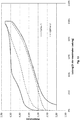
- 300 charge / discharge cycles were carried out in each case in [V3]. Table 1 below shows the reduction in the discharge capacity from the 5th cycle in comparison with the 300th cycle in%.
- a further development known from the prior art provides for the use of an electrolyte that contains sulfur dioxide (SO 2 ) as an additive, instead of a purely organic electrolyte for rechargeable battery cells.
- SO 2 sulfur dioxide
- the WO 2008/147751 A1 an electrolyte containing lithium salts such as LiAlCl 4 , nitriles, sulfur dioxide and polar, aprotic solvents such as ethylene carbonate (referred to as [V4]).
- this electrolyte is combined with a positive electrode made of, for example, lithium nickel manganese cobalt oxide.
- SO 2 sulfur dioxide
- Rechargeable battery cells which contain an SO 2 -based electrolyte, have, among other things, high ionic conductivity.
- SO 2 -based electrolyte is to be understood in the context of the present invention as an electrolyte which contains SO 2 not only as an additive in a low concentration, but in which the mobility of the ions of the conductive salt contained in the electrolyte and causes the charge transport, is at least partially, largely or even completely ensured by SO 2.
- the SO 2 thus serves as a solvent for the conductive salt.
- the conductive salt can form a liquid solvate complex with the gaseous SO 2 , whereby the SO 2 is bound and the vapor pressure is noticeably reduced compared to the pure SO 2. Electrolytes with low vapor pressure are produced. Such electrolytes based on SO 2 have the advantage of non-flammability compared to the organic electrolytes described above. Safety risks that exist due to the flammability of the electrolyte can thus be excluded.
- the EP 1 201 004 B1 an SO 2 -based electrolyte with the composition LiAlCl 4 * SO 2 in combination with a positive electrode made of LiCoO 2 (hereinafter referred to as [V5]).
- a positive electrode made of LiCoO 2 hereinafter referred to as [V5]
- [V5] suggests the use of a additional salt.
- the EP 2534719 B1 discloses an SO 2 -based electrolyte with, inter alia, LiAlCl 4 as the conductive salt.
- This LiAlCl 4 forms with the SO 2, for example, complexes of the formula LiAlCl 4 * 1.5 mol SO 2 or LiAlCl 4 * 6 mol SO 2 .
- Lithium iron phosphate LiFePO 4
- LiFePO 4 has a lower end-of-charge voltage (3.7 V) compared to LiCoO 2 (4.2 V). The problem of undesired overcharging reactions does not arise in this rechargeable battery cell, since upper potentials of 4.1 volts, which are harmful to the electrolyte, are not reached.
- SO 2 is a bad solvent for many conductive salts, such as lithium fluoride (LiF), lithium bromide (LiBr), lithium sulfate (Li 2 SO 4 ), lithium bis (o-xalato) borate (LiBOB), lithium hexafluoroarsenate (LiAsF 6 ) , Lithium tetrafluoroborate (LiBF 4 ), trilithium hexafluoroaluminate (Li 3 AlF 6 ), lithium hexafluoroantimonate (LiSbF 6 ), lithium difluoro (oxalato) borate (LiBF 2 C 2 O 4 ), lithium bis (trifluoromethanesulfonyl) imide (LiTFSI), lithium 2 ), lithium aluminate (LiAlO 2 ), lithium triflate (LiCF 3 SO 3 ) and lithium chlorosulfonate (LiSO 3 Cl).
- lithium fluoride
- Such rechargeable battery cells should in particular also have very good electrical energy and performance data, high operational reliability and service life, in particular a high number of usable charging and discharging cycles, without the electrolyte decomposing during operation of the rechargeable battery cell.
- a rechargeable battery cell comprises an active metal, at least one positive electrode, at least one negative electrode, a housing and an electrolyte.
- the positive electrode is designed as a high-voltage electrode.
- the electrolyte is based on SO 2 and contains at least a first conductive salt.
- This first conductive salt has the formula (I) on.
- M is a metal selected from the group formed by alkali metals, alkaline earth metals, metals of group 12 of the periodic table of the elements and aluminum.
- x is an integer from 1 to 3.
- the substituents R 1 , R 2 , R 3 and R 4 are independently selected from the group formed by C 1 -C 10 alkyl, C 2 -C 10 alkenyl, C 2 -C 10 alkynyl, C 3 -C 10 cycloalkyl, C 6 -C 14 aryl and C 5 -C 14 heteroaryl.
- the central atom Z is either aluminum or boron.
- high-voltage electrode in the context of the present invention is understood to mean electrodes which can be charged at least up to an upper potential of 4.0 volts.
- the high-voltage electrodes are preferably at least up to an upper potential of 4.4 volts, more preferably at least up to an upper potential of 4.8 volts, more preferably at least up to an upper potential of 5.2 volts, more preferably at least up to one upper potential of 5.6 volts and particularly preferably at least up to an upper potential of 6.0 volts in the rechargeable battery cell according to the invention.
- the upper potential corresponds to the end-of-charge voltage up to which a battery cell or battery made up of several battery cells is charged with the aid of a battery charger.
- Rechargeable battery cells according to the invention with high-voltage electrodes can have a cell voltage of at least 4.0 volts, more preferably of at least 4.4 volts, more preferably of at least 4.8 volts, more preferably of at least 5.2 volts, more preferably of at least 5.6 volts and particularly preferably of at least 6.0 volts.
- the SO 2 -based electrolyte used in the rechargeable battery cell according to the invention contains SO 2 not only as an additive in a low concentration, but in concentrations at which the mobility of the ions of the first conductive salt contained in the electrolyte and causes the charge transport, is at least partially, largely or even completely guaranteed by the SO 2.
- the first conductive salt is dissolved in the electrolyte and shows very good solubility therein. It can form a liquid solvate complex with the gaseous SO 2 , in which the SO 2 is bound. In this case, the vapor pressure of the liquid solvate complex drops significantly compared to the pure SO 2 and electrolytes with a low vapor pressure are formed.
- the production of the electrolyte according to the invention is carried out at low temperature or under pressure.
- the electrolyte can also contain several conductive salts of the formula (I), which differ from one another in their chemical structure.
- C 1 -C 10 alkyl comprises linear or branched saturated hydrocarbon groups with one to ten carbon atoms. These include, in particular, methyl, ethyl, n-propyl, isopropyl, n-butyl, sec-butyl, iso-butyl, tert-butyl, n-pentyl, iso-pentyl, 2,2-dimethylpropyl, n-hexyl, iso-hexyl , 2-ethylhexyl, n-heptyl, iso-heptyl, n-octyl, iso-octyl, n-nonyl, n-decyl, and the like.
- C 2 -C 10 alkenyl includes unsaturated linear or branched hydrocarbon groups with two to ten carbon atoms, the hydrocarbon groups having at least one CC double bond. These include, in particular, ethenyl, 1-propenyl, 2-propenyl, 1-n-butenyl, 2-n-butenyl, isobutenyl, 1-pentenyl, 1-hexenyl, 1-heptenyl, 1-octenyl, 1-nonenyl, 1 - Decenyl and the like.
- C 2 -C 10 alkynyl comprises unsaturated linear or branched hydrocarbon groups having two to ten carbon atoms, the hydrocarbon groups having at least one CC triple bond.
- these include in particular ethynyl, 1-propynyl, 2-propynyl, 1-n-butynyl, 2-n-butynyl, isobutynyl, 1-pentynyl, 1-hexynyl, 1-heptynyl, 1-octynyl, 1-nonynyl, 1 - decinyl and the like.
- C 3 -C 10 cycloalkyl encompasses cyclic, saturated hydrocarbon groups having three to ten carbon atoms. These include, in particular, cyclopropyl, cyclobutyl, cyclopentyl, cyclohexyl, cycloheptyl, cyclohexyl, cyclononyl and cyclodecanyl.
- C 6 -C 14 aryl includes aromatic hydrocarbon groups with six to fourteen ring carbon atoms. This includes in particular phenyl (C 6 H 5 group), naphthyl (C 10 H 7 group) and anthracyl (C 14 H 9 group).
- C 5 -C 14 heteroaryl includes aromatic hydrocarbon groups with five to fourteen ring hydrocarbon atoms in which at least one hydrocarbon atom has been replaced or exchanged by a nitrogen, oxygen or sulfur atom. These include, in particular, pyrrolyl, furanyl, thiophenyl, pyrridinyl, pyranyl, thiopyranyl and the like. All of the aforementioned hydrocarbon groups are each bonded to the central atom according to formula (I) via the oxygen atom.
- a rechargeable battery cell with such an electrolyte has the advantage over rechargeable battery cells with electrolytes known from the prior art that the first conductive salt contained therein has a higher oxidation stability and consequently shows essentially no decomposition at higher cell voltages.
- This electrolyte is stable to oxidation, preferably at least up to an upper potential of 4.0 volts, more preferably at least up to an upper potential of 4.2 volts, more preferably at least up to an upper potential of 4.4 volts, more preferably at least up to an upper potential of 4.6 volts, more preferably at least up to an upper potential of 4.8 volts and particularly preferably at least up to an upper potential of 5.0 volts.
- rechargeable battery cells according to the invention can have an end-of-charge voltage of at least 4.0 volts, more preferably of at least 4.4 volts, more preferably of at least 4.8 volts, more preferably of at least 5.2 volts, more preferably of at least 5.6 volts and particularly preferably of at least 6.0 volts.
- the service life of the rechargeable battery cell that contains this electrolyte is significantly longer than that of rechargeable battery cells that contain electrolytes known from the prior art. Furthermore, a rechargeable battery cell with such an electrolyte is also resistant to low temperatures. At a temperature of -40 ° C, for example, 61% of the charged capacity can still be discharged. The conductivity of the electrolyte at low temperatures is sufficient to operate a battery cell. Furthermore, a rechargeable battery cell with such an electrolyte has increased stability with respect to residual amounts of water.
- the electrolyte or the first conductive salt forms hydrolysis products with the water in comparison to the SO 2 -based electrolytes known from the prior art, which are clearly hydrolysis products are less aggressive towards the cellular components. Because of this, the absence of water in the electrolyte plays a less important role in comparison with the SO 2 -based electrolytes known from the prior art.
- the positive electrode is designed as a high-voltage electrode.
- the high-voltage electrode contains at least one active material. This active material can store ions of the active metal and release and take up the ions of the active metal during operation of the battery cell.
- the high-voltage electrode contains at least one intercalation connection.
- the term “intercalation compound” is to be understood as a sub-category of the insertion materials described above. This intercalation compound acts as a host matrix, which has vacancies that are interconnected. The ions of the active metal can diffuse into these voids during the discharge process of the rechargeable battery cell and be stored there. As part of this incorporation of the ions of the active metal, there are only minor or no structural changes in the host matrix.
- A is preferably the metal lithium, ie the compound can have the composition Li x M ' y M " z O a .
- the indices y and z in the composition A x M ' y M " z O a relate to the totality of metals and elements that are represented by M' and M", respectively.
- the indices x, y, z and a must be chosen so that there is charge neutrality within the composition.
- M phosphorus
- the following applies to the index z: z z1 + z2, where z1 and z2 are the indices of the metal M" 1 and of phosphorus (M " 2 ).
- the indices x, y, z and a must be chosen in such a way that charge neutrality prevails within the composition.
- the compound of the composition A x M ' y M " z O a can have the chemical structure of a spinel, a layered oxide or a polyanionic compound.
- the compound has the composition Li x M ' y M " z O a , in which A lithium, M' the metals nickel and manganese and M" the metal cobalt.
- this composition of the formula Li x Ni y1 Mn y2 Co z O a x, y1 and y2 are independently numbers greater than 0, z is a number greater than or equal to 0 and a is a number greater than 0.
- NMC Li x Ni y1 Mn y2 Co z O 2
- ie lithium n ickel m angan c obaltoxide which have the chemical structure of layer oxides.
- lithium nickel manganese cobalt oxide active materials LiNi 1/3 Mn 1/3 Co 1/3 O 2 (NMC111), LiNi 0.6 Mn 0.2 Co 0.2 O 2 (NMC622), and LiNi 0.8 Mn 0.1 Co 0.1 O 2 (NMC811).
- Further compounds of lithium nickel manganese cobalt oxide can have the composition LiNi 0.5 Mn 0.3 Co 0.2 O 2 , LiNi 0.5 Mn 0.25 Co 0.25 O 2 , LiNi 0.52 Mn 0.32 Co 0.16 O 2 , LiNi 0.55 Mn 0.30 Co 0.15 O 2 , LiNi 0.58 Mn 0.14 Co 0.28 O 2 , LiNi 0.64 Mn 0.18 Co 0.18 O 2 , LiNi 0, 65 Mn 0.27 Co 0.08 O 2 , LiNi 0.7 Mn 0.2 Co 0.1 O 2 , LiNi 0.7 Mn 0.15 Co 0.15 O 2 , LiNi 0.72 Mn 0.10 Co 0.18 O 2 , LiNi 0.76 Mn 0.14 Co 0.10 O 2 , LiNi 0.86 Mn 0.04 Co 0.10 O 2 , LiNi 0.90 Mn 0.05 Co 0.05 O 2 , LiNi 0.95 Mn 0.025 Co 0.025 O 2, or a combination thereof. These connections can be used to produce high
- the compound with the composition Li x M ' y M " z O a is a metal oxide that is rich in lithium and manganese.
- These metal oxides are also used in English referred to as "Lithium- and Manganese-Rich Oxide Materials” and can have the formula Li x Mn y M " z O a .
- These metal oxides Li x Mn y M " z O a can also have the chemical structure of layer oxides. This means that in this case M 'in the above-described formula Li x M' y M" z O a the metal manganese (Mn) is.
- the index x here is a number greater than or equal to 1
- the index y is a number greater than the index z or greater than the sum of the indices z1 + z2 + z3 etc.
- the index y y> z1 + z2.
- the index z is a number greater than or equal to 0 and the index a is a number greater than 0.
- Metal oxides that are rich in lithium and manganese can also be described by the formula mLi 2 MnO 3 ⁇ (1-m) LiM'O 2 with 0 ⁇ m ⁇ 1. Examples of such compounds are Li 1.2 Mn 0.525 Ni 0.175 Co 0.1 O 2 , Li 1.2 Mn 0.6 Ni 0.2 O 2 , Li 1.16 Mn 0.61 Ni 0.15 Co 0.16 O 2 or Li 1.2 Ni 0.13 Co 0.13 Mn 0.54 O 2 .
- These metal oxides Li x Mn y M " z O a and mLi 2 MnO 3 ⁇ (1-m) LiM'O 2 can have the chemical structure of layer oxides.
- a further advantageous development of the rechargeable battery cell according to the invention provides that the composition has the formula A x M ' y M " z O 4.
- a x M' y M " z O a has the value 4.
- These compounds are spinel structures. These spinel structures are intercalation compounds.
- A can be lithium, M 'cobalt and M "manganese.
- the active material is lithium cobalt manganese oxide (LiCoMnO 4 ).
- LiCoMnO 4 can be used to create high-voltage electrodes for rechargeable battery cells with a cell voltage of over 4.6 volts This Li-CoMnO 4 is preferably free of Mn 3+ .
- the compound thus has the composition A x M ' y M " z O a , where A is lithium, M' is manganese and M"
- the indices x, y and z preferably have the value 1 and a preferably the value 4, which is why this preferred compound is LiMnCoO 4 .
- the active material is lithium nickel manganese oxide (LiNiMnO 4 ).
- the molar proportions of the two metals M' and M" can vary.
- Lithium nickel manganese oxide can, for example, have the composition LiNi 0.5 Mn 1.5 O 4 .
- the high-voltage electrode contains at least one active material, which is designed as a conversion compound, as an active material.
- conversion compound in the context of the present invention is to be understood as a material in which chemical bonds are broken and re-established during electrochemical activity, ie during charging and discharging of the battery cell, whereby other materials are formed. Structural changes occur in the matrix of the conversion compound during the uptake or release of the ions of the active metal. Conversion compounds go through a solid-state redox reaction during the uptake of the active metal, e.g. lithium or sodium, in which the crystal structure changes of the material changes. This happens by breaking and recombining chemical bonds. Completely reversible reactions of conversion compounds can be, for example, as follows: MX z + y Li ⁇ M. + z Li Y Z X X + y Li ⁇ Li y X
- Examples of these conversion compounds are FeF 2 , FeF 3 , CoF 2 , CuF 2 , NiF 2 , BiF 3 , FeCl 3 , FeCl 2 , CoCl 2 , NiCl2, CuCl 2 , AgCl, LiCl, S, Li 2 S, Se, Li 2 Se, Te, I and Lil.
- the compound has the composition Li x M ' y M " 1 z1 M" 12 z2 O 4 , where M " 1 is at least one element selected from the group formed by the elements of Groups 2, 3, 4, 5, 6, 7, 8, 9, 10, 11, 12, 13, 14, 15 and 16 of the Periodic Table of the Elements, M " 2 is phosphorus, z1 is a number greater than or equal to 0 and z2 has the value 1.
- the compound with the composition Li x M ' y M " 1 z1 PO 4 is so-called lithium metal phosphates. These lithium metal phosphates can have the chemical structure of a polyanionic compound.
- this compound has the composition Li x Fe y Mn z1 PO 4
- lithium metal phosphates are lithium iron phosphate (LiFePO 4 ) or lithium iron manganese phosphates (Li (Fe y Mn z ) PO 4 ).
- An example of a lithium iron manganese phosphate is the phosphate with the composition Li (Fe 0.3 Mn 0.7 ) PO 4.
- Lithium metal phosphates of other compositions can also be used for the battery cell according to the invention can be used.
- the high-voltage electrode contains at least one metal compound.
- This metal compound is selected from the group which is formed by a metal oxide, a metal halide and a metal phosphate.
- the metal of this metal compound is preferably a transition metal with atomic numbers 22 to 28 of the Periodic Table of the Elements, in particular cobalt, nickel, manganese or iron.
- the high-voltage electrode contains at least one metal compound which has the chemical structure of a spinel, a layer oxide, a conversion compound or a polyanionic compound. It is within the scope of the invention that the high-voltage electrode is at least one of the compounds described or a combination of the compounds as the active material contains. A combination of the compounds is understood to mean a high-voltage electrode which contains at least two of the materials described.
- the high-voltage electrode comprises a discharge element.
- the high-voltage electrode also includes a discharge element in addition to the active material.
- This discharge element is used to enable the required electronically conductive connection of the active material of the positive electrode.
- the discharge element is in contact with the active material involved in the electrode reaction of the positive electrode.
- This diverting element can be designed in a planar manner in the form of a thin metal sheet or a thin metal foil.
- the thin metal foil preferably has an openwork or network-like structure.
- the planar diverting element can also consist of a plastic film coated with metal. These metal coatings have a thickness in the range from 0.1 ⁇ m to 20 ⁇ m.
- the active material of the positive electrode is preferably applied to the surface of the thin metal sheet, the thin metal foil or the metal-coated plastic foil.
- the active material can be applied to the front and / or the rear of the planar diverting element.
- Such planar discharge elements have a thickness in the range from 5 ⁇ m to 50 ⁇ m. A thickness of the planar discharge element in the range from 10 ⁇ m to 30 ⁇ m is preferred.
- the high-voltage electrode can have a total thickness of at least 20 ⁇ m, preferably at least 40 ⁇ m and particularly preferably at least 60 ⁇ m.
- the maximum thickness is at most 200 ⁇ m, preferably at most 150 ⁇ m and particularly preferably at most 100 ⁇ m.
- the area-specific capacity of the positive electrode based on the coating on one side is preferably at least 0.5 mAh / cm 2 when using a planar discharge element, the following values in this order being further preferred: 1 mAh / cm 2 , 3 mAh / cm 2, 5 mAh / cm 2, 10 mAh / cm 2, 15 mAh / cm 2, 20 mAh / cm 2.
- the discharge element of the positive electrode is designed three-dimensionally in the form of a porous metal structure, in particular in the form of a metal foam.
- the three-dimensional porous metal structure is so porous that the active material of the positive electrode can be incorporated into the pores of the metal structure.
- the amount of active material incorporated or applied is the charge on the positive electrode.
- the high-voltage electrode preferably has a thickness of at least 0.2 mm, preferably at least 0.3 mm, more preferably at least 0.4 mm, more preferably at least 0.5 mm and particularly preferably at least 0.6 mm.
- a further advantageous embodiment provides that the area-specific capacitance of the positive electrode when using a three-dimensional discharge element, in particular in the form of a metal foam, is preferably at least 2.5 mAh / cm 2 , the following values in this order being further preferred: 5 mAh / cm 2 , 15 mAh / cm 2 , 25 mAh / cm 2 , 35 mAh / cm 2 , 45 mAh / cm 2 , 55 mAh / cm 2 , 65 mAh / cm 2 , 75 mAh / cm 2 .
- the amount of active material of the positive electrode ie the loading of the electrode, based on its area, is at least 10 mg / cm 2 , preferably at least 20 mg / cm 2 , more preferably at least 40 mg / cm 2 , more preferably at least 60 mg / cm 2 , more preferably at least 80 mg / cm 2 and particularly preferably at least 100 mg / cm 2 .
- This charging of the positive electrode has a positive effect on the charging process and the discharging process of the rechargeable battery cell.
- the high-voltage electrode has at least one binding agent.
- This binder is preferably a fluorinated binder, in particular a polyvinylidene fluoride and / or a terpolymer formed from tetrafluoroethylene, hexafluoropropylene and vinylidene fluoride.
- a binder which consists of a polymer which is built up from monomeric structural units of a conjugated carboxylic acid or from the alkali, alkaline earth or ammonium salt of this conjugated carboxylic acid or from a combination thereof.
- the binder can also consist of a polymer based on monomeric styrene and butadiene structural units.
- the binder can also be a binder from the group of the carboxymethyl celluloses.
- the binder is in the positive electrode preferably in a concentration of at most 20% by weight, more preferably at most 15% by weight, further preferably at most 10% by weight, further preferably at most 7% by weight, further preferably at most 5% by weight and particularly preferably at most 2% by weight % based on the total weight of the positive electrode.
- C 1 -C 6 alkyl includes linear or branched saturated hydrocarbon groups with one to six hydrocarbon groups, in particular methyl, ethyl, n-propyl, isopropyl, n-butyl, sec -Butyl, iso-butyl, tert-butyl, n-pentyl, iso-pentyl, 2,2-dimethylpropyl, n-hexyl and iso-hexyl.
- C 2 -C 4 alkyls are preferred.
- the C 2 -C 4 alkyls 2-propyl, methyl and ethyl are particularly preferred.
- C 2 -C 6 alkenyl includes unsaturated linear or branched hydrocarbon groups with two to six carbon atoms, the hydrocarbon groups having at least one CC double bond. These include, in particular, ethenyl, 1-propenyl, 2-propenyl, 1-n-butenyl, 2-n-butenyl, isobutenyl, 1-pentenyl and 1-hexenyl, with C 2 -C 4 alkenyls being preferred. Ethenyl and 1-propenyl are particularly preferred.
- C 2 -C 6 alkynyl includes unsaturated linear or branched hydrocarbon groups having two to six carbon atoms, the hydrocarbon groups having at least one CC triple bond. These include, in particular, ethynyl, 1-propynyl, 2-propynyl, 1-n-butynyl, 2-n-butynyl, isobutynyl, 1-pentynyl and 1-hexynyl. Preferred among these are C 2 -C 4 -alkinyls.
- C 3 -C 6 cycloalkyl includes cyclic saturated hydrocarbon groups with three to six carbon atoms. This includes in particular cyclopropyl, cyclobutyl, cyclopentyl and cyclohexyl.
- C 5 -C 7 heteroaryl includes phenyl and naphthyl.
- the substituents R 1 , R 2 , R 3 and R 4 are substituted by at least one fluorine atom and / or by at least one chemical group in a further advantageous embodiment of the rechargeable battery cell , the chemical group being selected from the group formed by C 1 -C 4 -alkyl, C 2 -C 4 -alkenyl, C 2 -C 4 -alkynyl, phenyl and benzyl.
- the chemical groups C 1 -C 4 -alkyl, C 2 -C 4 -alkenyl, C 2 -C 4 -alkynyl, phenyl and benzyl have the same properties or chemical structures as the hydrocarbon groups described above. Substituted in this context means that individual atoms or groups of atoms of the substituents R 1 , R 2 , R 3 and R 4 have been replaced by the fluorine atom and / or by the chemical group.
- a particularly high solubility of the first conductive salt in the SO 2 -based electrolyte can be achieved if at least one of the substituents R 1 , R 2 , R 3 and R 4 is a CF 3 group or an OSO 2 CF 3 group .
- the first conductive salt is selected from the group formed by
- the electrolyte has at least one second conductive salt different from the first conductive salt according to formula (I).
- the electrolyte can contain one or more second conductive salts, which differ from the first conductive salt in terms of their chemical composition and their chemical structure.
- the second conductive salt is an alkali metal compound, in particular a lithium compound.
- the alkali metal compound or the lithium compound are selected from the group formed by an aluminate, a halide, an oxalate, a borate, a phosphate, an arsenate and a gallate.
- the second conductive salt is preferably a lithium tetrahaloaluminate, in particular LiAlCl 4 .
- the electrolyte can contain not only a first conductive salt according to formula (I) and a second conductive salt, but in each case also several first conductive salts according to formula (I) and several second conductive salts. In the latter case, the aforementioned percentages also include several first conductive salts and several second conductive salts.
- the molar concentration of the first conductive salt is in the range from 0.01 mol / l to 10 mol / l, preferably from 0.05 mol / l to 10 mol / l, more preferably from 0.1 mol / l to 6 mol / l and particularly preferably from 0.2 mol / l to 3.5 mol / l based on the total volume of the electrolyte.
- the electrolyte contains at least 0.1 mol SO 2 , preferably at least 1 mol SO 2 , more preferably at least 5 mol SO 2 , more preferably at least 10 mol SO 2 and particularly preferably at least 20 mol Contains SO 2 per mole of conductive salt.
- the electrolyte can also contain very high molar proportions of SO 2 , the preferred upper limit being 2600 mol SO 2 per mol of conductive salt and upper limits of 1500, 1000, 500 and 100 mol of SO 2 per mol of conductive salt in this order being further preferred are.
- the term "per mole of conductive salt” refers to all conductive salts contained in the electrolyte.
- Electrolytes based on SO 2 with such a concentration ratio between SO 2 and the conductive salt have the advantage that they can dissolve a larger amount of conductive salt compared to the electrolytes known from the prior art, which are based, for example, on an organic solvent mixture.
- an electrolyte with a relatively low concentration of conductive salt is advantageous despite the associated higher vapor pressure, in particular with regard to its stability over many charging and discharging cycles of the rechargeable battery cell.
- the concentration of SO 2 in the electrolyte affects its conductivity.
- the conductivity of the electrolyte can be adapted to the planned use of a rechargeable battery cell operated with this electrolyte.
- the total content of SO 2 and the first conductive salt can be greater than 50 percent by weight (% by weight) of the weight of the electrolyte, preferably greater than 60% by weight, more preferably greater than 70% by weight, more preferably greater than 80% by weight, more preferably greater than 85% by weight, more preferably greater than 90% by weight, more preferably greater than 95% by weight or more preferably greater than 99% by weight.
- the negative electrode is an insertion electrode.
- This insertion electrode contains an insertion material as the active material, in which the ions of the active metal can be stored during the charging of the rechargeable battery cell and from which the ions of the active metal can be removed during the discharge of the rechargeable battery cell.
- the electrode processes can take place not only on the surface of the negative electrode, but also inside the negative electrode. If, for example, a conductive salt based on lithium is used, then lithium ions can be stored in the insertion material while the rechargeable battery cell is being charged and the rechargeable battery cell can be removed therefrom while the rechargeable battery cell is being discharged.
- the negative electrode preferably contains carbon as the active material or insertion material, in particular in the modification graphite.
- the carbon is present in the form of natural graphite (flake conveying means or rounded), synthetic graphite (mesophase graphite), graphitized MesoCarbon MicroBeads (MCMB), with carbon-coated graphite or amorphous carbon.
- the negative electrode comprises lithium intercalation anode active materials that contain no carbon, for example lithium titanates (eg Li 4 Ti 5 O 12 ).
- the negative electrode comprises lithium alloy-forming anode active materials.
- lithium-storing metals and metal alloys e.g. Si, Ge, Sn, SnCo x C y , SnSi x and the like
- oxides of lithium-storing metals and metal alloys e.g. SnO x , SiO x , oxidic glasses of Sn, Si and the like.
- the negative electrode contains conversion anode active materials.
- conversion anode active materials can, for example, transition metal oxides in the form of manganese oxides (MnO x ), iron oxides (FeO x ), cobalt oxides (CoO x ), nickel oxides (NiO x ), copper oxides (CuO x ) or metal hydrides in the form of magnesium hydride (MgH 2 ), Titanium hydride (TiH 2 ), aluminum hydride (AlH 3 ), and boron, aluminum and magnesium based ternary hydrides and the like.
- the negative electrode comprises a metal, in particular metallic lithium.
- the negative electrode is porous, the porosity preferably at most 50%, more preferably at most 45%, more preferably at most 40%, more preferably at most 35%, more preferably at most 30%, more preferably at most 20% and particularly preferably at most 10%.
- the porosity represents the volume of the cavity in relation to the total volume of the negative electrode, the volume of the cavity being formed by so-called pores or cavities. This porosity leads to an increase in the inner surface area of the negative electrode. Furthermore, the porosity reduces the density of the negative electrode and thus also its weight.
- the individual pores of the negative electrode can preferably be completely filled with the electrolyte during operation.
- the negative electrode has a discharge element.
- the negative electrode also comprises a discharge element in addition to the active material or insertion material.
- This discharge element is used to enable the required electronically conductive connection of the active material of the negative electrode.
- the discharge element is in contact with the active material involved in the electrode reaction of the negative electrode.
- This diverting element can be designed in a planar manner in the form of a thin metal sheet or a thin metal foil.
- the thin metal foil preferably has an openwork or network-like structure.
- the planar diverting element can also consist of a plastic film coated with metal. These metal coatings have a thickness in the range from 0.1 ⁇ m to 20 ⁇ m.
- the active material of the negative electrode is preferably applied to the surface of the thin metal sheet, the thin metal foil or the metal-coated plastic foil.
- the active material can be on the front and / or the back of the planar discharge element be upset.
- Such planar discharge elements have a thickness in the range from 5 ⁇ m to 50 ⁇ m.
- a thickness of the planar discharge element in the range from 10 ⁇ m to 30 ⁇ m is preferred.
- the negative electrode can have a total thickness of at least 20 ⁇ m, preferably at least 40 ⁇ m and particularly preferably at least 60 ⁇ m.
- the maximum thickness is at most 200 ⁇ m, preferably at most 150 ⁇ m and particularly preferably at most 100 ⁇ m.
- the area-specific capacitance of the negative electrode based on the coating on one side is preferably at least 0.5 mAh / cm 2 when a planar discharge element is used, the following values in this order being further preferred: 1 mAh / cm 2 , 3 mAh / cm 2, 5 mAh / cm 2, 10 mAh / cm 2, 15 mAh / cm 2, 20 mAh / cm 2.
- the diverting element can be designed three-dimensionally in the form of a porous metal structure, in particular in the form of a metal foam.
- the term "three-dimensional porous metal structure" denotes any structure made of metal which not only extends over the length and width of the flat electrode like the thin metal sheet or the metal foil, but also over its thickness dimension.
- the three-dimensional porous metal structure is so porous that the active material of the negative electrode can be incorporated into the pores of the metal structure.
- the amount of active material incorporated or applied is the charge on the negative electrode.
- the discharge element is designed three-dimensionally in the form of a porous metal structure, in particular in the form of a metal foam, then the negative electrode preferably has a thickness of at least 0.2 mm, preferably at least 0.3 mm, more preferably at least 0.4 mm, more preferably at least 0.5 mm and particularly preferably at least 0.6 mm. In this case, the thickness of the electrodes is significantly greater compared to negative electrodes, which are used in organic lithium-ion cells.
- a further advantageous embodiment provides that the area-specific capacitance of the negative electrode when using a three-dimensional discharge element, in particular in the form of a metal foam, is preferably at least 2.5 mAh / cm 2 , the following values in this order being further preferred: 5 mAh / cm 2 , 15 mAh / cm 2 , 25 mAh / cm 2 , 35 mAh / cm 2 , 45 mAh / cm 2 , 55 mAh / cm 2 , 65 mAh / cm 2 , 75 mAh / cm 2 .
- the amount of active material of the negative electrode ie the loading of the electrode, based on its area, is at least 10 mg / cm 2 , preferably at least 20 mg / cm 2 , more preferably at least 40 mg / cm 2 , more preferably at least 60 mg / cm 2 , more preferably at least 80 mg / cm 2 and particularly preferably at least 100 mg / cm 2 .
- This charging of the negative electrode has a positive effect on the charging process and the discharging process of the rechargeable battery cell.
- the negative electrode has at least one binding agent.
- This binder is preferably a fluorinated binder, in particular a polyvinylidene fluoride and / or a terpolymer formed from tetrafluoroethylene, hexafluoropropylene and vinylidene fluoride.
- a binder which consists of a polymer which is built up from monomeric structural units of a conjugated carboxylic acid or from the alkali, alkaline earth or ammonium salt of this conjugated carboxylic acid or from a combination thereof.
- the binder can also consist of a polymer based on monomeric styrene and butadiene structural units.
- the binder can also be a binder from the group of the carboxymethyl celluloses.
- the binder is in the negative electrode preferably in a concentration of at most 20% by weight, more preferably at most 15% by weight, further preferably at most 10% by weight, further preferably at most 7% by weight, further preferably at most 5% by weight and particularly preferably at most 2% by weight % based on the total weight of the negative electrode.
- the negative electrode has at least one conductivity additive.
- the conductivity additive should preferably have a low weight, a high chemical resistance and a high specific surface
- examples of conductivity additives are particulate carbon (carbon black, Super P, acetylen black), fibrous carbon (CarbonNanoTtubes CNT, carbon (nano) fibers), finely divided Graphites and graphs (nanosheets).
- the rechargeable battery cell comprises several negative electrodes and several high-voltage electrodes, which are stacked alternately in the housing.
- the positive electrodes and the negative electrodes are preferably each electrically separated from one another by separators.
- the separator can be formed from a fleece, a membrane, a woven fabric, a knitted fabric, an organic material, an inorganic material or a combination thereof.
- Organic separators can consist of unsubstituted polyolefins (eg polypropylene or polyethylene), partially to completely halogen-substituted polyolefins (eg partially to completely fluorine-substituted, in particular PVDF, ETFE, PTFE), polyesters, polyamides or polysulfones.
- Separators that contain a combination of organic and inorganic materials are, for example, glass fiber textile materials in which the glass fibers are provided with a suitable polymer coating.
- the coating preferably contains a fluorine-containing polymer such as polytetrafluoroethylene (PTFE), ethylene-tetrafluoroethylene (ETFE), perfluoroethylene propylene (FEP), THV (terpolymer of tetrafluoroethylene, hexafluoroethylene and vinylidene fluoride), a perfluoroalkoxy polymer (PFA), aminosilane, polypropylene or polyethylene (PE).
- PTFE polytetrafluoroethylene
- ETFE ethylene-tetrafluoroethylene
- FEP perfluoroethylene propylene
- THV terpolymer of tetrafluoroethylene, hexafluoroethylene and vinylidene fluoride
- PFA perfluoroalkoxy polymer
- the separator can also be folded in the housing of the rechargeable battery cell, for example in the form of a so-called “Z-folding”. In this Z-folding, a strip-shaped separator is folded in a z-like manner through or around the electrodes. Furthermore, the separator can also be designed as separator paper. It is also within the scope of the invention that the separator can be designed as a cover, each high-voltage electrode or each negative electrode being covered by the cover. The covering can be formed from a fleece, a membrane, a woven fabric, a knitted fabric, an organic material, an inorganic material or a combination thereof. Covering the positive electrode leads to more uniform ion migration and ion distribution in the rechargeable battery cell.
- the surface dimensions of the electrodes and the covering can preferably be matched to one another in such a way that the outer dimensions of the covering of the electrodes and the outer dimensions of the uncovered electrodes match at least in one dimension.
- the area of the envelope can preferably be greater than the area of the electrode.
- the sheath extends beyond a boundary of the electrode.
- Two layers of the casing covering the electrode on both sides can therefore be connected to one another at the edge of the positive electrode by an edge connection.
- the negative electrodes have a cover, while the positive electrodes have no cover.
- FIG. 1 shows a first exemplary embodiment of a rechargeable battery cell 2 according to the invention in a cross-sectional illustration.
- This rechargeable battery cell 2 is designed as a prismatic cell and has, among other things, a housing 1.
- This housing 1 encloses an electrode arrangement 3 which comprises three positive electrodes 4 and four negative electrodes 5.
- the positive electrodes 4 and the negative electrodes 5 are stacked alternately in the electrode arrangement 3.
- the positive electrode 4 is designed as a high-voltage electrode.
- the housing 1 can also accommodate more positive electrodes 4 in the form of high-voltage electrodes and / or negative electrodes 5. In general, it is preferred if the number of negative electrodes 5 is one greater than the number of positive electrodes 4.
- the outer end faces of the electrode stack are formed by the electrode surfaces of the negative electrodes 5.
- the electrodes 4, 5 are connected to corresponding connection contacts 9, 10 of the rechargeable battery cell 2 via electrode connections 6, 7.
- the rechargeable battery cell 2 is filled with an SO 2 -based electrolyte in such a way that the electrolyte penetrates as completely as possible into all pores or cavities, in particular within the electrodes 4, 5.
- the positive electrodes 4 contain an intercalation compound as an active material. This intercalation compound is LiCoMnO 4 with a spinel structure.
- the electrodes 4, 5 are designed to be flat, that is to say as layers with a smaller thickness in relation to their surface area.
- the housing 1 of the rechargeable battery cell 2 is essentially cuboid, the electrodes 4, 5 and the walls of the housing 1 shown in sectional view extending perpendicular to the plane of the drawing and being essentially straight and flat.
- the rechargeable battery cell 2 can, however, also be designed as a winding cell which the electrodes consist of thin layers that are wound together with a separator material.
- the electrodes 4, 5 also have a discharge element which serves to enable the required electronically conductive connection of the active material of the respective electrode.
- This discharge element is in contact with the active material involved in the electrode reaction of the respective electrode 4, 5 (in Figure 1 not shown).
- the diverting element is designed in the form of a porous metal foam 18.
- the metal foam 18 extends over the thickness dimension of the electrodes 4, 5.
- the active material of the positive electrodes 4 and the negative electrodes 5 is each incorporated into the pores of this metal foam 18 so that it fills its pores evenly over the entire thickness of the metal structure.
- the positive electrodes 4 contain a binder. This binder is a fluoropolymer.
- the negative electrodes 5 contain carbon as an active material in a form suitable as an insertion material for receiving lithium ions.
- the structure of the negative electrode 5 is similar to that of the positive electrode 4.
- FIG. 13 shows an electron microscope image of the three-dimensional porous structure of the metal foam 18 of the first exemplary embodiment from FIG Figure 1 .
- the pores P have an average diameter of more than 100 ⁇ m, that is to say they are relatively large.
- This metal foam is a metal foam made of nickel.
- FIG Figure 3 shows a second exemplary embodiment of a rechargeable battery cell 20 according to the invention in a cross-sectional illustration.
- the electrode arrangement comprises a positive electrode 23 and two negative electrodes 22. They are each separated from one another by separators 21 and surrounded by a housing 28.
- the positive electrode 23 has a discharge element 26 in the form of a planar metal foil, to which the active material 24 of the positive electrode 23 is applied on both sides.
- the negative electrodes 22 also include a discharge element 27 in the form of a planar metal foil, to which the active material 25 of the negative electrode 22 is applied on both sides.
- planar discharge elements of the edge electrodes that is to say of the electrodes that terminate the electrode stack, can only be coated on one side with active material.
- the non-coated side faces the wall of the housing 28.
- the electrodes 22, 23 are connected to corresponding connection contacts 31, 32 of the rechargeable battery cell 20 via electrode connections 29, 30.
- Figure 4 shows the planar metal foil, which is used as a discharge element 26, 27 for the positive electrodes 23 and the negative electrodes 22 in the second exemplary embodiment Figure 3 serves.
- This metal foil has a perforated or network-like structure with a thickness of 20 ⁇ m.
- FIG Figure 5 shows a third embodiment of a rechargeable battery cell 40 according to the invention in an exploded view.
- This third exemplary embodiment differs from the two exemplary embodiments explained above in that the positive electrode 44 is encased by a sheath 13. In this case, the area of the envelope 13 is greater than the area of the positive electrode 44, the delimitation 14 of which in FIG Figure 5 is shown as a dashed line.
- Two layers 15, 16 of the casing 13 that cover the positive electrode 44 on both sides are connected to one another at the circumferential edge of the positive electrode 44 by an edge connection 17.
- the two negative electrodes 45 are not covered.
- the electrodes 44 and 45 can be contacted via the electrode connections 46 and 47.
- a reference electrolyte used for the examples described below was prepared according to the method described in FIG Patent specification EP 2 954 588 B1 procedure described (in Hereafter referred to as [V7]).
- lithium chloride (LiCl) was dried under vacuum at 120 ° C. for three days.
- Aluminum particles (AI) were dried under vacuum for two days at 450 ° C.
- LiCl, aluminum chloride (AlCl 3 ) and Al were mixed with one another in a molar ratio AlCl 3 : LiCl: Al of 1: 1.06: 0.35 in a glass bottle with an opening that allows gas to escape. Then, this mixture was gradually heat-treated to produce a molten salt.
- the reference electrolyte thus formed had the composition LiAlCl 4 * x SO 2 , where x is dependent on the amount of SO 2 supplied.
- the respective concentration of the compounds 1, 2, 3 and 4 in the electrolytes 1, 2, 3 and 4 was 0.6 mol / l (molar concentration based on 1 liter of the electrolyte), provided that nothing else is described in the experiment description.
- the experiments described below were carried out with electrolytes 1, 2, 3 and 4 and the reference electrolyte.
- the test full cells used in the experiments described below are rechargeable battery cells with two negative electrodes and one positive electrode, each separated by a separator.
- the positive electrodes comprised an active material, a conductivity mediator and a binder.
- the negative electrodes contained graphite as an active material and also a binder. As mentioned in the experiment, the negative electrodes can also contain a conductivity additive.
- the active material of the positive electrode is named in the respective experiment.
- the discharge element of the positive and negative electrodes was made of nickel.
- the aim of the investigations is to confirm the use of various active materials for the positive electrode in a battery cell according to the invention with a high upper potential (charging potential). Table 3 shows which active materials of the high-voltage electrode were examined and which upper potentials were used.
- test full cells were each filled with the electrolyte required for the experiments, ie either with the reference electrolyte or electrolytes 1, 2, 3 or 4.
- electrolyte required for the experiments
- Several, ie two to four, identical test whole cells were produced for each experiment.
- the results presented in the experiments are in each case mean values from the measured values obtained for the identical test whole cells.
- the discharge capacity is determined from the number of cycles.
- the test full cells are charged with a certain charging current up to a certain upper potential.
- the corresponding upper potential is held until the charging current has dropped to a certain value.
- the discharge takes place with a certain discharge current strength up to a certain discharge potential.
- This charging method is called I / U charging. This process is repeated depending on the desired number of cycles.
- the upper potentials or the discharge potential and the respective charging and discharging currents are named in the experiments. The value to which the charging current must have dropped is also described in the experiments.
- upper potential is used synonymously with the terms “charging potential”, “charging voltage”, “end-of-charge voltage” and “upper potential limit.”
- the terms refer to the voltage / potential up to which a cell or battery is charged with the aid of a battery charger.
- the full test cells are preferably charged with a current rate of C / 2 and at a temperature of 22 ° C. With a charge or discharge rate of 1C, by definition, the Nominal capacity of a cell charged or discharged in one hour. A charging rate of C / 2 therefore means a charging time of 2 hours.
- discharge potential is used synonymously with the term “lower cell voltage”.
- the battery is preferably discharged at a current rate of C / 2 and at a temperature of 22 ° C.
- the discharge capacity is obtained from the discharge current and the time until the criteria for ending the discharge are met.
- the associated figures show mean values for the discharge capacities as a function of the number of cycles. These mean values of the discharge capacities are expressed as a percentage of the nominal capacity, often standardized to the maximum capacity that was achieved in the respective test.
- the nominal capacity is obtained by subtracting from the theoretical capacity of the positive electrode that capacity which is consumed in the first cycle for the formation of a cover layer on the negative electrode. This cover layer is formed on the negative electrode when the full test cell is charged for the first time. Lithium ions are irreversibly consumed for this top layer formation, so that the respective test full cell has less cyclic capacity for the subsequent cycles.
- test full cells An experiment in test full cells according to Example 3 was carried out with positive electrodes made of lithium nickel manganese cobalt oxide with the composition LiNi 0.6 Mn 0.2 Co 0.2 O 2 (NMC622) and LiNi 0.8 Mn 0.1 Co 0.1 O 2 (NMC811) as active electrode materials.
- Compounds of the composition NMC can be charged up to high upper potentials in a battery cell with a suitable electrolyte and then discharged again.
- the test full cells were filled with the electrolyte 1 described in Example 2.
- Three test full cells contained high-voltage electrodes with the compound NMC622, in one test full cell NMC811 was used as the active high-voltage cathode material.
- test full cells were charged with a current of 50 mA up to different upper potentials. The corresponding upper potential was held until the charging current had dropped to 40 mA. The discharge then took place with a current of 50 mA up to a discharge potential of 2.5 volts.
- the upper potentials were for the three NMC622 test full cells at 4.4 volts, at 4.6 volts and at 5.0 volts, respectively.
- the upper potential of the NMC811 test full cell was 4.6 volts.
- Figure 6 shows mean values for the discharge capacities of the four test full cells as a function of the number of cycles. These mean values of the discharge capacities are expressed as a percentage of the nominal capacity [% nominal capacity].
- the cathode material NMC (622) in battery cells from the prior art shows at an upper potential of 4.4 volts in the 300th cycle only a discharge capacity of 94% and at an upper potential of 4.6 volts only a discharge capacity of 39%.
- a cell according to the invention with NMC (622) cathode material shows a discharge capacity of 97% in the 300th cycle at 4.4 volts, a discharge capacity of 91% at 4.6 volts and a very high upper potential of 5.0 Volt even has a value of 84%.
- the cathode material NMC (811) shows a discharge capacity of 66% in the 300th cycle at an upper potential of 4.4 volts.
- the same material still has a high discharge capacity of 90% at an upper potential of 4.6 volts.
- Example 3 Two test whole cells according to Example 3 were produced.
- the active material of the positive electrodes consisted of lithium cobalt oxide (LCO).
- a first test full cell was filled with a reference electrolyte according to Example 1 for this experiment 2.
- the electrolyte had the composition LiAlCl 4 * 6 SO 2 .
- the second test full cell was filled with the electrolyte 1 described in Example 2.
- the test full cells were cycled according to the description in experiment 1.
- the upper potential of the battery cells with reference electrolyte was 4.2 volts, that of the cells according to the invention was 4.4 volts.
- Figure 7 shows mean values for the discharge capacities of the two test full cells as a function of the number of cycles.
- Figure 8 shows mean values for the discharge capacities of these two test full cells as a function of the number of cycles. These mean values of the discharge capacities are expressed as a percentage of the nominal capacity [% nominal capacity].
- the discharge capacity of the first test full cell with reference electrolyte begins to drop steadily from the 75th cycle after previous fluctuations. At cycle 130 a capacity of only 86% is reached. The first test full cell is irreversibly damaged.
- a battery cell that contains a combination of an electrode with lithium nickel manganese cobalt oxide (NMC) with the composition LiNi 0.6 Mn 0.2 Co 0.2 O 2 (NMC622) as the active material and the reference electrolyte is not stable at an upper potential of 4.2 volts.
- the second test full cell shows a very stable behavior of the discharge capacity. At cycle 200, a capacity of 97% is still retained.
- a test full cell was produced according to Example 3 with lithium iron phosphate LiFePO 4 (LEP) as the active electrode material of the positive electrode.
- the full test cell was filled with the electrolyte 1 described in Example 2.
- Figure 9 shows the potential curve in volts [V] over the percentage charge, which is related to the maximum charge of the test full cell [% of the max. charge].
- the test full cell was charged with a current of 50 mA up to an upper potential of 5 V. The potential was held until the charging current had dropped to 40 mA. The discharge then took place with a current of 50 mA up to a discharge potential of 2.5 volts.
- Example 3 In order to test further lithium metal phosphates as active electrode material, a test full cell according to Example 3 was produced in a further experiment.
- the active material of the positive electrodes (cathodes) consisted of lithium iron manganese phosphate Li (Fe 0.3 Mn 0.7 ) PO 4 .
- the full test cell was filled with the electrolyte 1 described in Example 2.
- the upper potential of the full test cell is 4.5 volts.
- Figure 11 shows mean values for the discharge capacities of the test full cell as a function of the number of cycles. These mean values of the discharge capacities are expressed as a percentage of the nominal capacity.
- the test full cell shows a very stable behavior of the discharge capacity. At cycle 200 a capacity of 97% is still obtained.
- Example 3 In order to test a metal oxide, which is rich in lithium and manganese, as the active electrode material, a test full cell according to Example 3 was produced in a further experiment.
- the active material of the positive electrodes (cathodes) consisted of a metal oxide with the composition Li 1.16 Mn 0.61 Ni 0.15 Co 0.16 O 2 , which is rich in lithium and manganese.
- the full test cell was filled with the electrolyte 1 described in Example 2. To determine the discharge capacities (see Example 4), the test full cell was charged with a current of 100 mA up to an upper potential of 4.8 volts. That The corresponding upper potential was held until the charging current had dropped to 40 mA. The discharge then took place with a current of 100 mA up to a discharge potential of 2.0 volts.
- Figure 12 shows mean values for the discharge capacities of the test full cell as a function of the number of cycles. These mean values of the discharge capacities are expressed as a percentage of the nominal capacity [% nominal capacity].
- the test full cell shows a very stable behavior of the discharge capacity. At cycle 100, a capacity of 90% is still obtained.
- Figure 13 shows the potential curve in volts [v] of cycle 1 and cycle 2 of a test full cell with a metal oxide that is rich in lithium and manganese. The metal oxide is activated in the first cycle, which enables the high specific capacities typical of this material.
- the potential profile is shown as a percentage of the charge, which is related to the maximum charge of the test full cell.
- the test full cell was charged with a current of 100 mA up to an upper potential of 4.8 V.
- test cell with a three-electrode arrangement (working electrode, counter electrode and reference electrode) was produced in a further experiment.
- the active material of the positive electrode (cathode) consisted of a metal oxide with the composition LiNi 0.5 Mn 1.5 O 4 .
- the counter electrode and the reference electrode were made of metallic lithium.
- the test cell was filled with the electrolyte 1 described in Example 2.
- Figure 14 shows the potential profile of cycles 1 and 2 in volts [V] as a function of capacity.
- the test cell was charged at a charge rate of 0.1 C up to an upper potential of 5 V.
- the discharge then took place at a discharge rate of 0.1 C up to a discharge potential of 3.5 volts.
- a high capacity of 154 mAh / g is achieved in cycle 1.
- the capacity drops slightly in cycle 2.
- the test full cells were charged with a current of 15 mA until a capacity of 125 mAh (Q lad ) was reached.
- the test full cells were then discharged at 15 mA until a potential of 2.5 volts was reached.
- the discharge capacity (Q ent ) was determined.
- Q NEL is the theoretical capacity of the negative electrode used. In the case of graphite, the theoretical capacity is calculated to be 372 mAh / g.
- the absolute capacity losses are 7.58% and 11.51% for electrolytes 1 and 3 and 6.85% for the reference electrolytes.
- the capacity for the formation of the top layer is somewhat higher with both electrolytes according to the invention than with Reference electrolytes. Values in the range of 7.5% - 11.5% for the absolute capacity losses are good results in combination with the possibility of using high-voltage cathodes up to 5 volts.
- three test full cells according to Example 3 were filled with the electrolytes 1, 3 and 4 described in Example 2.
- the test full cells had lithium nickel manganese cobalt oxide (NMC) as the active material of the positive electrode.
- NMC lithium nickel manganese cobalt oxide
- the test full cells were charged with a current of 15 mA up to a capacity of 125 mAh. The discharge then took place with a current of 15 mA up to a discharge potential of 2.5 volts.
- Figure 16 shows the potential curve during the discharge over the discharged amount of charge in% [% of the maximum charge (discharge)]. All test full cells show a flat discharge curve, which is necessary for a good operation of a battery cell.
- electrolytes 1, 3 and 4 were prepared with different concentrations of compounds 1, 3 and 4. For each concentration of the various compounds, the conductivities of the electrolytes were determined using a conductive measurement method. After temperature control, a two-electrode sensor was held in touch with the solution and measured in a measuring range of 0-50 mS / cm. During the measurements it was noted that the sensor can react with the SO 2 -containing electrolyte solution.
- Figure 17 shows the conductivity of the electrolyte 1 as a function of the concentration of the compound 1. A maximum of the conductivity can be seen at a concentration of the compound 1 of 0.6 mol / L-0.7 mol / L with a value of approx. 37.9 mS / cm.
- the organic electrolytes known from the prior art such as LP30 (1 M LiPF6 / EC-DMC (1: 1 wt.)
- LP30 1 M LiPF6 / EC-DMC (1: 1 wt.)
- Electrolyte 3 shows the conductivity values determined for the different concentrations for electrolytes 3 and 4.
- electrolyte 4 a maximum of 18 mS / cm is achieved at a conductive salt concentration of 1 mol / L.
- Electrolyte 3 shows its highest conductivity of 0.5 mS / cm at a conductive salt concentration of 0.6 mol / L.
- electrolyte 3 shows a lower conductivity, as in experiment 4, charging or discharging of a test full cell is quite possible.
- test full cells In order to determine the low-temperature behavior of the electrolyte 1 in comparison to the reference electrolyte, two test full cells according to Example 3 were produced.
- One test full cell was filled with reference electrolyte with the composition LiAlCl 4 * 6SO 2 and the other test full cell with electrolyte 1.
- the test full cell with the reference electrolyte contained lithium iron phosphate (LEP) as the active material
- the test cell with electrolyte 1 contained lithium nickel manganese cobalt oxide (NMC) as the active material of the positive electrode.
- the test full cells were charged to 3.6 volts (LEP) or 4.4 volts (NMC) at 20 ° C. and discharged again to 2.5 volts at the respective temperature to be examined.
- the discharge capacity reached at 20 ° C was rated as 100%.
- the temperature for the discharge was lowered in temperature steps of 10 ° K.
- the discharge capacity obtained was described in% of the discharge capacity at 20 ° C. Since the low-temperature discharges are almost independent of the active materials used for the positive and negative electrodes, the results can be transferred to all combinations of active materials. Table 5 shows the results.
- Electrolyte discharge capacity 1 Discharge capacity of the reference electrolyte 20 ° C 100% 100% 10 ° C 99% 99% 0 ° C 95% 46% -10 ° C 89% 21% -20 ° C 82% n / A -30 ° C 73% n / A -35 ° C 68% n / A -40 ° C 61% n / A
- test full cell with electrolyte 1 shows very good low-temperature behavior. At - 20 ° C, 82% of the capacity is still achieved, at - 30 ° C, 73%. Even at a temperature of -40 ° C, 61% of the capacity can still be discharged. In contrast to this, the test full cell with the reference electrolyte only shows a discharge capacity down to - 10 ° C. A capacity of 21% is achieved. At lower temperatures, the cell with the reference electrolyte can no longer be discharged.
Landscapes
- Chemical & Material Sciences (AREA)
- Chemical Kinetics & Catalysis (AREA)
- Electrochemistry (AREA)
- General Chemical & Material Sciences (AREA)
- Engineering & Computer Science (AREA)
- Inorganic Chemistry (AREA)
- Manufacturing & Machinery (AREA)
- Materials Engineering (AREA)
- Organic Chemistry (AREA)
- Condensed Matter Physics & Semiconductors (AREA)
- General Physics & Mathematics (AREA)
- Physics & Mathematics (AREA)
- Composite Materials (AREA)
- Crystallography & Structural Chemistry (AREA)
- Secondary Cells (AREA)
- Battery Electrode And Active Subsutance (AREA)
- Cell Electrode Carriers And Collectors (AREA)
- Primary Cells (AREA)
Description
- Die Erfindung betrifft eine wiederaufladbare Batteriezelle mit einem auf SO2-basierenden Elektrolyt.
- Wiederaufladbare Batteriezellen sind auf vielen technischen Gebieten von großer Bedeutung. Vielfach werden sie für Anwendungen eingesetzt, bei denen nur kleine wiederaufladbare Batteriezellen mit relativ geringen Stromstärken benötigt werden, wie beispielsweise beim Betrieb von Mobiltelefonen. Daneben gibt es aber auch einen großen Bedarf an größeren wiederaufladbaren Batteriezellen für Hochenergieanwendungen, wobei eine Massenspeicherung von Energie in Form von Batteriezellen für den elektrischen Antrieb von Fahrzeugen von besonderer Bedeutung ist.
- Eine wichtige Anforderung bei derartigen wiederaufladbaren Batteriezellen ist eine hohe Energiedichte. Das bedeutet, dass die wiederaufladbare Batteriezelle möglichst viel elektrische Energie je Gewichts- und Volumeneinheit enthalten soll. Hierfür hat sich Lithium als aktives Metall als besonders vorteilhaft erwiesen. Als aktives Metall einer wiederaufladbaren Batteriezelle bezeichnet man das Metall, dessen Ionen innerhalb des Elektrolyten beim Laden oder Entladen der Zelle zur negativen oder positiven Elektrode wandern und dort an elektrochemischen Prozessen teilnehmen. Diese elektrochemischen Prozesse führen direkt oder indirekt zur Abgabe von Elektronen in den externen Stromkreis oder zur Aufnahme von Elektronen aus dem externen Stromkreis. Wiederaufladbare Batteriezellen, welche Lithium als aktives Metall enthalten, werden auch als Lithium-Ionen-Zellen bezeichnet. Die Energiedichte dieser Lithium-Ionen-Zellen kann entweder durch Steigerung der spezifischen Kapazität der Elektroden oder durch Steigerung der Zellspannung erhöht werden.
- Sowohl die positive als auch die negative Elektrode von Lithium-Ionen-Zellen sind als Insertionselektroden ausgebildet. Unter dem Begriff "Insertionselektrode" im Sinne der vorliegenden Erfindung werden Elektroden verstanden, welche eine Kristallstruktur aufweisen, in die Ionen des aktiven Materials beim Betrieb der Lithium-Ionen-Zelle ein- und ausgelagert werden können. Das bedeutet, dass sich die Elektrodenprozesse nicht nur an der Oberfläche der Elektroden, sondern auch innerhalb der Kristallstruktur abspielen können.
- Beim Laden der Lithium-Ionen-Zelle werden die Ionen des aktiven Metalls aus der positiven Elektrode ausgelagert und in die negative Elektrode eingelagert. Beim Entladen der Lithium-Ionen-Zelle läuft der umgekehrte Prozess ab.
- Auch der Elektrolyt ist ein wichtiges Funktionselement jeder wiederaufladbaren Batteriezelle. Er enthält meistens ein Lösungsmittel oder ein Lösungsmittelgemisch und mindestens ein Leitsalz. Feststoffelektrolyte oder ionische Flüssigkeiten enthalten zum Beispiel kein Lösungsmittel, sondern nur das Leitsalz. Der Elektrolyt steht mit der positiven und der negativen Elektrode der Batteriezelle in Kontakt. Mindestens ein Ion des Leitsalzes (Anion oder Kation) ist in dem Elektrolyten derartig beweglich, dass durch Ionenleitung ein für die Funktion der wiederaufladbaren Batteriezelle erforderlicher Ladungstransport zwischen den Elektroden stattfinden kann. Der Elektrolyt wird ab einer bestimmten oberen Zellspannung der wiederaufladbaren Batteriezelle oxidativ elektrochemisch zersetzt. Dieser Vorgang führt oft zu einer irreversiblen Zerstörung von Bestandteilen des Elektrolyten und damit zu einem Ausfall der wiederaufladbaren Batteriezelle. Auch reduktive Prozesse können den Elektrolyten ab einer bestimmten unteren Zellspannung zersetzen. Um diese Prozesse zu vermeiden, werden die positive und die negative Elektrode derart gewählt, dass die Zellspannung unter- bzw. oberhalb der Zersetzungsspannung des Elektrolyten liegt. Der Elektrolyt bestimmt somit das Spannungsfenster (in Engl.: voltage window), in dessen Bereich eine wiederaufladbare Batteriezelle reversibel betrieben, das heißt (d.h.) wiederholt aufgeladen und entladen werden kann.
- Die aus dem Stand der Technik bekannten Lithium-Ionen-Zellen enthalten einen Elektrolyten, der aus einem in einem organischen Lösungsmittel oder Lösungsmittelgemisch und einem darin gelösten Leitsalz besteht. Bei dem Leitsalz handelt es sich um ein Lithiumsalz wie beispielsweise Lithiumhexafluorophosphat (LiPF6). Das Lösungsmittelgemisch kann beispielsweise Ethylencarbonat enthalten. Der Elektrolyt LP57, der die Zusammensetzung 1 M LiPF6 in EC:EMC 3:7 aufweist, ist ein Beispiel für einen solchen Elektrolyten. Aufgrund des organischen Lösungsmittels oder Lösungsmittelgemischs werden derartige Lithium-Ionen-Zellen auch als organische Lithium-Ionen-Zellen bezeichnet.
- Neben dem im Stand der Technik häufig verwendeten Lithiumhexafluorophosphat (LiPF6) als Leitsalz werden auch andere Leitsalze für organische Lithium-Ionen-Zellen beschrieben. So beschreibt zum Beispiel das Dokument
JP 4 306858 B2 JP 2001 143750 A - Die negative Elektrode vieler organischer Lithium-Ionen-Zellen besteht aus einer Kohlenstoffbeschichtung, welche auf ein Ableitelement aus Kupfer aufgetragen ist. Das Ableitelement stellt den erforderlichen elektronisch leitenden Anschluss zwischen der Kohlenstoffbeschichtung und dem externen Stromkreis her. Die positive Elektrode besteht aus Lithiumcobaltoxid (LiCoO2), welches auf ein Ableitelement aus Aluminium aufgetragen ist. Beide Elektroden weisen eine Dicke von in der Regel weniger als 100 µm auf und sind daher sehr dünn ausgebildet. Es ist seit langem bekannt, dass das ungewollte Überladen von organischen Lithium-Ionen-Zellen zu einer irreversiblen Zersetzung von Elektrolytkomponenten führt. Dabei findet die oxidative Zersetzung des organischen Lösungsmittels und/oder des Leitsalzes an der Oberfläche der positiven Elektrode statt. Die während dieser Zersetzung gebildete Reaktionswärme und die dabei entstehenden gasförmigen Produkte sind für den darauffolgenden, sogenannten "Thermal Runaway" (englisch für "thermisches Durchgehen") und die dadurch resultierende Zerstörung der organischen Lithium-Ionen-Zelle verantwortlich. Die überwiegende Mehrheit an Ladeprotokollen für diese organischen Lithium-Ionen-Zellen zieht die Zellspannung als Indikator für das Ladeende heran. Hierbei sind Unfälle durch den Thermal Runaway besonders wahrscheinlich bei der Verwendung von Multizellen-Batteriepacks, in denen mehrere organische Lithium-Ionen-Zellen mit nicht übereinstimmenden Kapazitäten in Reihe geschaltet werden. Deshalb sind organische Lithium-Ionen-Zellen problematisch hinsichtlich ihrer Stabilität sowie langfristigen Betriebssicherheit. Sicherheitsrisiken werden insbesondere auch durch die Brennbarkeit des organischen Lösungsmittels oder Lösungsmittelgemischs verursacht. Wenn eine organische Lithium-Ionen-Zelle Feuer fängt oder sogar explodiert, bildet das organische Lösungsmittel des Elektrolyten ein brennbares Material. Um solche Sicherheitsrisiken zu vermeiden, müssen zusätzliche Maßnahmen getroffen werden. Zu diesen Maßnahmen zählen insbesondere eine sehr exakte Regelung der Lade- und Entladevorgänge der organischen Lithium-Ionen-Zelle sowie eine optimierte Batteriekonstruktion. Weiterhin enthält die organische Lithium-Ionen-Zelle Komponenten, die bei ungewollter Temperaturerhöhung schmelzen und hierbei die organische Lithium-Ionen-Zelle mit geschmolzenem Kunststoff fluten können. Dadurch wird eine weitere unkontrollierte Temperaturerhöhung vermieden. Diese Maßnahmen führen jedoch zu erhöhten Produktionskosten bei der Herstellung der organischen Lithium-Ionen-Zelle sowie zu einem erhöhten Volumen und Gewicht. Weiterhin vermindern diese Maßnahmen die Energiedichte der organischen Lithium-Ionen-Zelle.
- Ein weiterer Nachteil von organischen Lithium-Ionen-Zellen besteht darin, dass etwaige in Anwesenheit von Restmengen an Wasser entstehende Hydrolyseprodukte gegenüber den Zellkomponenten der wiederaufladbaren Batteriezelle sehr aggressiv sind. So entsteht beispielsweise bei dem häufig in organischen Zellen verwendeten Leitsalz LiPF6 durch Reaktion mit Wasserspuren sehr reaktiver, aggressiver Fluorwasserstoff (HF). Aufgrund dessen muss bei der Herstellung derartiger wiederaufladbarer Batteriezellen mit einem organischen Elektrolyten auf eine Minimierung des im Elektrolyten und den Zellkomponenten enthaltenen Restwassergehalts geachtet werden. Die Produktion findet deshalb oft in kostenintensiven Trockenräumen mit extrem niedriger Luftfeuchtigkeit statt. Die zuvor beschriebenen Probleme im Hinblick auf die Stabilität und die langfristige Betriebssicherheit sind besonders schwerwiegend bei der Entwicklung von organischen Lithium-Ionen-Zellen, die zum einen sehr gute elektrische Energie- und Leistungsdaten und zum anderen eine sehr hohe Betriebssicherheit und Lebensdauer, insbesondere eine hohe Zahl nutzbarer Lade- und Entladezyklen aufweisen.
- Um die Energiedichte von organischen Lithium-Ionen-Zellen zu erhöhen, wurden im Stand der Technik neue Kathodenmaterialien, d.h. neue aktive Materialien für positive Elektroden getestet, die mit einer höheren Ladeschlussspannung, d.h. einem höheren oberen Potential gezykelt werden können. Solche aktive Materialien sind z.B. Lithiumnickelmangancobaltoxide, die abgekürzt auch als NMC bezeichnet werden. Die folgende Veröffentlichung berichtet darüber:
- "Oxygen Release and Its Effect on the Cycling Stability of LiNixMnyCozO2 (NMC)
- Cathode Materials for Li-Ion Batteries"
- Roland Jung; Michael Metzger; Filippo Maglia; Christoph Stinner and Hubert A. Gasteigera.
- Journal of The Electrochemical Society, 164 (7) A1361-A1377 (2017 )
- Diese Veröffentlichung von Jung et al. ist im nachfolgenden als [V3] bezeichnet. Jung et al. haben in der [V3] verschiedene NMC-Materialien mit der Zusammensetzung NMC(xyz) getestet. Die Kleinbuchstaben (xyz) in der Klammer geben die Indizes x, y und z der Verbindung LiNixMnyCozO2 an. In der [V3] wurden drei verschiedene NMC-Kathodenmaterialien in einer organischen Lithium-Ionen-Zelle mit dem zuvor beschriebenen LP57 Elektrolyt (1 M LiPF6 in EC:EMC 3:7) bei verschiedenen Ladeschlussspannungen gezykelt. Bei der Ladeschlussspannung handelt es um die Spannung, bis zu welcher eine einzelne Batteriezelle oder Batterie aus mehreren Batteriezellen mit Hilfe einer Batterieladevorrichtung geladen wird. Oft werden die Batterien mit einer bestimmten Ladestromstärke bis zu einem bestimmten oberen Potential, das heißt bis zu der Ladeschlussspannung geladen. Das entsprechende obere Potential wird so lange gehalten, bis der Ladestrom auf einen bestimmten Wert abgesunken ist. In der [V3] wurden jeweils 300 Lade-/ Entladezyklen durchgeführt. In der unten dargestellten Tabelle 1 ist jeweils die Reduzierung der Entladekapazität vom 5. Zyklus im Vergleich mit dem 300. Zyklus in % angegeben.
- Aus dieser Tabelle 1 geht hervor, dass es bei den Materialien NMC(111) und NMC(622) zu einem drastischen Kapazitätsrückgang beim Zyklen mit einer Ladeschlussspannung von 4,6 Volt kommt, denn es werden nur noch 42% bzw. 39% der ursprünglichen Kapazität erreicht. Das Material NMC(811) wurde nur bis 4,4 Volt gezykelt, wobei ebenfalls eine stetige Abnahme der Kapazität bei Erhöhung der Ladeschlussspannung beobachtet wurde. Anhand der [V3] lässt sich daher feststellen, dass organische Lithium-Ionen-Zellen mit den NMC-Kathodenmaterialien zwar bei einem höheren oberen Potenzial gezykelt werden können. Der Nachteil besteht allerdings darin, dass es dabei zu einer unerwünscht hohen Kapazitätsabnahme kommt.
Tabelle 1: Entladekapazitäten bei steigenden Ladeschlussspannungen aus der [V3] von Jung et al. 4.0 V 4.2 V 4.4 V 4.6 V Material Entladekapazität [%] Entladekapazität [%] Entladekapazität [%] Entladekapazität [%] NMC(111) - 93% 94% 42% NMC(622) - 95% 94% 39% NMC(811) 90% 77% 66% - - Eine aus dem Stand der Technik bekannte Weiterentwicklung sieht die Verwendung eines Elektrolyten vor, der Schwefeldioxid (SO2) als Additiv enthält, anstatt eines rein organischen Elektrolyten für wiederaufladbare Batteriezellen. Beispielweise geht aus der
WO 2008/147751 A1 ein Elektrolyt hervor, der Lithiumsalze wie beispielsweise LiAlCl4, Nitrile, Schwefeldioxid und polare, aprotische Lösungsmittel wie beispielsweise Ethylencarbonat enthält (bezeichnet als [V4]). In einer wiederaufladbaren Batteriezelle wird dieser Elektrolyt mit einer positiven Elektrode aus z.B. Lithiumnickelmangancobaltoxide kombiniert. - Eine weitere aus dem Stand der Technik bekannte Weiterentwicklung sieht die Verwendung eines Elektrolyten auf Schwefeldioxid (SO2)-Basis anstatt eines organischen Elektrolyten für wiederaufladbare Batteriezellen vor. Wiederaufladbare Batteriezellen, welche einen auf SO2-basierenden Elektrolyten enthalten, weisen unter anderem eine hohe ionische Leitfähigkeit auf. Unter dem Begriff "auf SO2-basierender Elektrolyt" ist im Sinne der vorliegenden Erfindung ein Elektrolyt zu verstehen, der SO2 nicht nur als Zusatz in geringer Konzentration enthält, sondern bei dem die Beweglichkeit der Ionen des Leitsalzes, das in dem Elektrolyten enthalten ist und den Ladungstransport bewirkt, zumindest teilweise, größtenteils oder sogar vollständig durch SO2 gewährleistet ist. Das SO2 dient also als Lösungsmittel für das Leitsalz. Das Leitsalz kann mit dem gasförmigen SO2 einen flüssigen Solvatkomplex bilden, wobei das SO2 gebunden und der Dampfdruck gegenüber dem reinen SO2 merklich gesenkt wird. Es entstehen Elektrolyte mit niederem Dampfdruck. Derartige Elektrolyten auf SO2-Basis haben im Vergleich zu den zuvor beschriebenen organischen Elektrolyten den Vorteil der Nichtbrennbarkeit. Sicherheitsrisiken, welche durch die Brennbarkeit des Elektrolyten bestehen, können dadurch ausgeschlossen werden.
- Beispielsweise geht aus der
EP 1 201 004 B1 ein auf SO2-basierender Elektrolyt mit der Zusammensetzung LiAlCl4 * SO2 in Kombination mit einer positiven Elektrode aus LiCoO2 hervor (im Nachfolgenden bezeichnet als [V5]). Zur Vermeidung von störenden Zersetzungsreaktionen bei der Überladung der wiederaufladbaren Batteriezelle ab einem oberen Potential von 4,1 bis 4,2 Volt, wie beispielsweise die unerwünschte Bildung von Chlor (CI2) aus Lithiumtetrachloroaluminat (LiAlCl4), schlägt die [V5] die Verwendung eines zusätzlichen Salzes vor. - Auch die
EP 2534719 B1 (im Nachfolgenden bezeichnet als [V6]) offenbart einen auf SO2-basierenden Elektrolyten mit unter anderem LiAlCl4 als Leitsalz. Dieses LiAlCl4 bildet mit dem SO2 beispielsweise Komplexe der Formel LiAlCl4* 1,5 mol SO2 oder LiAlCl4* 6 mol SO2. Als positive Elektrode wird in der [V6] Lithiumeisenphosphat (LiFePO4) verwendet. LiFePO4 hat eine geringere Ladeschlussspannung (3,7 V) im Vergleich zu LiCoO2 (4,2 V). Die Problematik der unerwünschten Überladereaktionen tritt in dieser wiederaufladbaren Batteriezelle nicht auf, da für den Elektrolyten schädliche obere Potentiale von 4,1 Volt nicht erreicht werden. - Ein Nachteil, der unter anderem auch bei diesen auf SO2-basierenden Elektrolyten auftritt, besteht darin, dass etwaige in Anwesenheit von Restmengen an Wasser entstehende Hydrolyseprodukte mit den Zellkomponenten der wiederaufladbaren Batteriezelle reagieren und dadurch zur Bildung von unerwünschten Nebenprodukten führen. Aufgrund dessen muss bei der Herstellung derartiger wiederaufladbare Batteriezellen mit einem auf SO2-basierenden Elektrolyten auf eine Minimierung des im Elektrolyten und den Zellkomponenten enthaltenen Restwassergehalts geachtet werden.
- Ein weiteres Problem bei den auf SO2-basierenden Elektrolyten besteht darin, dass viele, insbesondere auch für organische Lithium-Ionen-Zellen bekannte Leitsalze nicht in SO2 löslich sind.
Tabelle 2: Löslichkeiten verschiedener Leitsalze in SO2 Leitsalz Löslichkeit / mol/L in SO 2 Leitsalz Löslichkeit / mol/L in SO 2 LiF 2,1·10-3 LiPF6 1,5·10-2 LiBr 4.9·10-3 LiSbF6 2.8·10-4 Li2SO4 2.7·10-4 LiBF2(C2O4) 1,4·10-4 LiB(C2O4)2 3.2·10-4 CF3SO2NLiSO2CF3 1,5·10-2 Li3PO4 - LiBO2 2.6·10-4 Li3AlF6 2,3·10-3 LiAlO2 4.3·10-4 LiBF4 1.7·10-3 LiCF3SO3 6.3·10-4 LiAsF6 1,4·10-3 - Messungen ergaben, dass SO2 ein schlechtes Lösungsmittel für viele Leitsalze ist, wie z.B. Lithiumfluorid (LiF), Lithiumbromid (LiBr), Lithiumsulfat (Li2SO4), Lithiumbis(o-xalato)borat (LiBOB), Lithiumhexafluoroarsenat (LiAsF6), Lithiumtetrafluorborat (LiBF4), Trilithiumhexafluoroaluminat (Li3AlF6), Lithiumhexafluoroantimonat (LiSbF6), Lithium Difluoro(oxalato)borat (LiBF2C2O4), Lithium-bis(trifluoromethansulfonyl)imid (LiTFSI), Lithiummetaborat (LiBO2), Lithiumaluminat (LiAlO2), Lithiumtriflat (LiCF3SO3) und Lithiumchlorsulfonat (LiSO3Cl). Die Löslichkeiten dieser Leitsalze liegen in SO2 bei ca. 10-2 - 10-4 mol/L (siehe Tabelle 2). Bei diesen geringen Salz-Konzentrationen kann davon ausgegangen werden, dass allenfalls nur geringe Leitfähigkeiten vorliegen, die für den sinnvollen Betrieb einer wiederaufladbaren Batteriezelle nicht ausreichend sind.
- Um die Einsatzmöglichkeiten sowie Eigenschaften von wiederaufladbaren Batteriezellen, die einen auf SO2-basierenden Elektrolyten enthalten, weiter zu verbessern, liegt der vorliegenden Erfindung die Aufgabe zugrunde, eine wiederaufladbare Batteriezelle mit auf SO2-basierenden Elektrolyten anzugeben, die gegenüber den aus dem Stand der Technik bekannten wiederaufladbaren Batteriezellen
- ein breites elektrochemisches Fenster hat, sodass keine oxidative Elektrolytzersetzung an der positiven Elektrode auftritt;
- eine stabile Deckschicht auf der negativen Elektrode aufweist, wobei die Deckschichtkapazität niedrig sein sollte und im weiteren Betrieb keine weitere reduktive Elektrolytzersetzung an der negativen Elektrode auftritt;
- einen auf SO2-basierenden Elektrolyten enthält, der eine für Leitsalze gute Löslichkeit aufweist und damit ein guter lonenleiter und elektronischer Isolator ist, damit der lonentransport erleichtert und die Selbstentladung auf ein Minimum beschränkt werden kann;
- einen auf SO2-basierenden Elektrolyten enthält, der auch gegenüber anderen Komponenten der wiederaufladbaren Batteriezelle, wie Separatoren, Elektrodenmaterialien und Zellverpackungsmaterialien, inert ist,
- gegen verschiedene Missbräuche, wie elektrische, mechanische oder thermische, robust ist;
- einen auf SO2-basierenden Elektrolyten enthält, der eine gesteigerte Stabilität gegenüber Restmengen an Wasser in den Zellkomponenten von wiederaufladbaren Batteriezellen aufweist;
- verbesserte elektrische Leistungsdaten, insbesondere eine hohe Energiedichte aufweist;
- eine verbesserte Überladefähigkeit und Tiefentladefähigkeit und eine geringere Selbstentladung aufweist und
- eine gesteigerte Lebensdauer, insbesondere eine hohe Zahl nutzbarer Lade- und Entladezyklen zeigt.
- Derartige wiederaufladbare Batteriezellen sollen insbesondere auch sehr gute elektrische Energie- und Leistungsdaten, eine hohe Betriebssicherheit und Lebensdauer, insbesondere eine hohe Zahl nutzbarer Lade- und Entladezyklen aufweisen, ohne dass sich hierbei der Elektrolyt im Betrieb der wiederaufladbaren Batteriezelle zersetzt.
- Gelöst wird diese Aufgabe durch eine wiederaufladbare Batteriezelle mit den Merkmalen des Anspruchs 1. Die Ansprüche 2 bis 30 beschreiben vorteilhafte Weiterbildungen der erfindungsgemäßen wiederaufladbaren Batteriezelle.
- Eine erfindungsgemäße wiederaufladbare Batteriezelle umfasst ein aktives Metall, zumindest eine positive Elektrode, zumindest eine negative Elektrode, ein Gehäuse und einen Elektrolyten. Die positive Elektrode ist als Hochvoltelektrode ausgebildet. Der Elektrolyt basiert auf SO2 und enthält zumindest ein erstes Leitsalz. Dieses erste Leitsalz weist die Formel (I)

- Unter dem Begriff "Hochvoltelektrode" im Sinne der vorliegenden Erfindung werden Elektroden verstanden, die mindestens bis zu einem oberen Potential von 4,0 Volt ladbar sind. Bevorzugt sind die Hochvoltelektroden mindestens bis zu einem oberen Potential von 4,4 Volt, weiter bevorzugt mindestens bis zu einem oberen Potential von 4,8 Volt, weiter bevorzugt mindestens bis zu einem oberen Potential von 5,2 Volt, weiter bevorzugt mindestens bis zu einem oberen Potential von 5,6 Volt und besonders bevorzugt mindestens bis zu einem oberen Potential von 6,0 Volt in der erfindungsgemäßen wiederaufladbaren Batteriezelle ladbar. Das obere Potential entspricht dabei der Ladeschlussspannung, bis zu welchem eine Batteriezelle oder Batterie aus mehreren Batteriezellen mit Hilfe einer Batterieladevorrichtung geladen wird. Erfindungsgemäße wiederaufladbare Batteriezellen mit Hochvoltelektroden können eine Zellspannung von mindestens 4,0 Volt, weiter bevorzugt von mindestens 4,4 Volt, weiter bevorzugt von mindestens 4,8 Volt, weiter bevorzugt von mindestens 5,2 Volt, weiter bevorzugt von mindestens 5,6 Volt und besonders bevorzugt von mindestens 6,0 Volt aufweisen.
- Der in der erfindungsgemäßen wiederaufladbaren Batteriezelle verwendete, auf SO2-basierende Elektrolyt enthält SO2 nicht nur als Zusatz in geringer Konzentration, sondern in Konzentrationen, bei denen die Beweglichkeit der Ionen des ersten Leitsalzes, das in dem Elektrolyten enthalten ist und den Ladungstransport bewirkt, zumindest teilweise, größtenteils oder sogar vollständig durch das SO2 gewährleistet ist. Das erste Leitsalz ist in dem Elektrolyten gelöst und zeigt darin eine sehr gute Löslichkeit. Es kann mit dem gasförmigen SO2 einen flüssigen Solvatkomplex bilden, in welchem das SO2 gebunden wird. In diesem Fall sinkt der Dampfdruck des flüssigen Solvatkomplexes gegenüber dem reinen SO2 deutlich und es entstehen Elektrolyte mit niederem Dampfdruck. Es liegt jedoch auch im Rahmen der Erfindung, dass es bei der Herstellung des erfindungsgemäßen Elektrolyten, je nachdem welche chemische Struktur das erste Leitsalz nach Formel (I) hat, zu keiner Dampfdruckerniedrigung kommen kann. Im letztgenannten Fall ist es bevorzugt, dass bei der Herstellung des erfindungsgemäßen Elektrolyten bei Tieftemperatur oder unter Druck gearbeitet wird. Der Elektrolyt kann auch mehrere Leitsalze der Formel (I) enthalten, welche in ihrer chemischen Struktur voneinander abweichen.
- Der Begriff "C1-C10 Alkyl" umfasst im Sinne der vorliegenden Erfindung lineare oder verzweigte gesättigte Kohlenwasserstoffgruppen mit einem bis zehn Kohlenstoffatomen. Hierunter fallen insbesondere Methyl, Ethyl, n-Propyl, Isopropyl, n-butyl, sec-Butyl, iso-Butyl, tert-Butyl, n-Pentyl, iso-Pentyl, 2,2-Dimethylpropyl, n-Hexyl, iso-Hexyl, 2-Ethylhexyl, n-Heptyl, iso-Heptyl, n-Octyl, iso-Octyl, n-Nonyl, n-Decyl und dergleichen.
Der Begriff "C2-C10 Alkenyl" umfasst im Sinne der vorliegenden Erfindung ungesättigte lineare oder verzweigte Kohlenwasserstoffgruppen mit zwei bis zehn Kohlenstoffatomen, wobei die Kohlenwasserstoffgruppen zumindest eine C-C-Doppelbindung aufweisen. Hierunter fallen insbesondere Ethenyl, 1-Propenyl, 2- Propenyl, 1-n-Butenyl, 2-n-Butenyl, iso-Butenyl, 1-Pentenyl, 1-Hexenyl, 1-Heptenyl, 1-Octenyl, 1-Nonenyl, 1- Decenyl und dergleichen.
Der Begriff "C2-C10 Alkinyl" umfasst im Sinne der vorliegenden Erfindung ungesättigte lineare oder verzweigte Kohlenwasserstoffgruppen mit zwei bis zehn Kohlenstoffatomen, wobei die Kohlenwasserstoffgruppen zumindest eine C-C-Dreifachbindung aufweisen. Hierunter fallen insbesondere Ethinyl, 1-Propinyl, 2- Propinyl, 1-n-Butinyl, 2-n-Butinyl, iso-Butinyl, 1-Pentinyl, 1- Hexinyl, 1-Heptinyl, 1-Octinyl, 1-Noninyl, 1- Decinyl und dergleichen. Der Begriff "C3-C10 Cycloalkyl" umfasst im Sinne der vorliegenden Erfindung zyklische, gesättigte Kohlenwasserstoffgruppen mit drei bis zehn Kohlenstoffatomen. Hierunter fallen insbesondere Cyclopropyl, Cyclobutyl, Cyclopentyl, Cyclohexyl, Cycloheptyl, Cyclohexyl, Cyclononyl und Cyclodecanyl. - Der Begriff "C6-C14 Aryl" umfasst im Sinne der vorliegenden Erfindung aromatische Kohlenwasserstoffgruppen mit sechs bis vierzehn ringständigen Kohlenstoffatomen. Hierunter fallen insbesondere Phenyl (C6H5 Gruppe), Naphthyl (C10H7 Gruppe) und Anthracyl (C14H9 Gruppe).
Der Begriff "C5-C14 Heteroaryl" umfasst im Sinne der vorliegenden Erfindung aromatische Kohlenwasserstoffgruppen mit fünf bis vierzehn ringständigen Kohlenwasserstoffatomen, bei welchen zumindest ein Kohlenwasserstoff-Atom durch ein Stickstoff-, Sauerstoff- oder Schwefel-Atom ersetzt bzw. ausgetauscht ist. Hierunter fallen insbesondere Pyrrolyl, Furanyl, Thiophenyl, Pyrridinyl, Pyranyl, Thiopyranyl und dergleichen. Alle der vorgenannten Kohlenwasserstoffgruppen sind jeweils über das Sauerstoff-Atom an Zentralatom gemäß Formel (I) gebunden. - Ein wiederaufladbare Batteriezelle mit einem derartigen Elektrolyt hat gegenüber wiederaufladbaren Batteriezellen mit aus dem Stand der Technik bekannten Elektrolyten den Vorteil, dass das darin enthaltene erste Leitsalz eine höhere Oxidationsstabilität aufweist und infolgedessen im Wesentlichen keine Zersetzung bei höheren Zellspannungen zeigt. Dieser Elektrolyt ist oxidationsstabil bevorzugt mindestens bis zu einem oberen Potential von 4,0 Volt, weiter bevorzugt mindestens bis zu einem oberen Potential von 4,2 Volt, weiter bevorzugt mindestens bis zu einem oberen Potential von 4,4 Volt, weiter bevorzugt mindestens bis zu einem oberen Potential von 4,6 Volt, weiter bevorzugt mindestens bis zu einem oberen Potential von 4,8 Volt und besonders bevorzugt mindestens bis zu einem oberen Potential von 5,0 Volt. Somit kommt es bei der Verwendung eines solchen Elektrolyten in einer wiederaufladbaren Batteriezelle zu einer nur geringen oder sogar gar keinen Elektrolytzersetzung innerhalb der Arbeitspotentiale, d.h. im Bereich zwischen der Ladeschlussspannung und der Entladeschlussspannung beider Elektroden der wiederaufladbaren Batteriezelle. Dadurch können erfindungsgemäße wiederaufladbare Batteriezellen eine Ladeschlussspannung von mindestens 4,0 Volt, weiter bevorzugt von mindestens 4,4 Volt, weiter bevorzugt von mindestens 4,8 Volt, weiter bevorzugt von mindestens 5,2 Volt, weiter bevorzugt von mindestens 5,6 Volt und besonders bevorzugt von mindestens 6,0 Volt aufweisen. Die Lebensdauer der wiederaufladbaren Batteriezelle, die diesen Elektrolyten enthält, ist gegenüber wiederaufladbaren Batteriezellen, die aus dem Stand der Technik bekannten Elektrolyten enthalten, deutlich verlängert.
Weiterhin ist eine wiederaufladbaren Batteriezelle mit einem solchem Elektrolyten auch tieftemperaturfest. Bei einer Temperatur von z.B. -40°C können noch 61% der geladenen Kapazität entladen werden. Die Leitfähigkeit des Elektrolyten bei tiefen Temperaturen ist ausreichend zum Betrieb einer Batteriezelle. Weiterhin weist eine wiederaufladbaren Batteriezelle mit einem solchem Elektrolyten eine gesteigerte Stabilität gegenüber Restmengen an Wasser auf. Sofern sich in dem Elektrolyten noch geringe Restmengen an Wasser (im ppm-Bereich) befinden, bildet der Elektrolyt bzw. das erste Leitsalz mit dem Wasser im Vergleich zu den aus dem Stand der Technik bekannten, auf SO2-basierenden Elektrolyten Hydrolyseprodukte, welche deutlich weniger aggressiv gegenüber den Zellkomponenten sind. Aufgrund dessen spielt eine Wasserfreiheit des Elektrolyts im Vergleich zu den aus dem Stand der Technik bekannten, auf SO2-basierenden Elektrolyten eine weniger bedeutende Rolle. Diese Vorteile des erfindungsgemäßen Elektrolyten überwiegen den Nachteil, der dadurch entsteht, dass das erste Leitsalz nach Formel (I) eine im Vergleich zu den aus dem Stand der Technik bekannten Leitsalze deutlich höhere Anionengröße aufweist. Diese höhere Anionengröße führt zu einer im Vergleich zur Leitfähigkeit von LiAlCl4 geringeren Leitfähigkeit des ersten Leitsalzes gemäß Formel (I). - Nachfolgend sind vorteilhafte Weiterbildungen der erfindungsgemäßen wiederaufladbaren Batteriezelle im Hinblick auf die positive Elektrode beschrieben:
Die positive Elektrode ist erfindungsgemäß als Hochvoltelektrode ausgebildet. Die Hochvoltelektrode enthält in einer vorteilhaften Weiterbildung der erfindungsgemäßen wiederaufladbaren Batteriezelle mindestens ein aktives Material. Dieses aktive Material kann Ionen des aktiven Metalls speichern und während des Betriebs der Batteriezelle die Ionen des aktiven Metalls abgeben und wieder aufnehmen. - Die Hochvoltelektrode enthält in einer weiteren vorteilhaften Weiterbildung der erfindungsgemäßen wiederaufladbaren Batteriezelle zumindest eine Interkalationsverbindung. Unter dem Begriff "Interkalationsverbindung" ist im Sinne der vorliegenden Erfindung eine Unterkategorie der zuvor beschriebenen Insertionsmaterialien zu verstehen. Diese Interkalationsverbindung fungiert als Wirtsmatrix, welche Leerstellen aufweist, die untereinander verbunden sind. In diese Leerstellen können die Ionen des aktiven Metalls während des Entladevorgangs der wiederaufladbaren Batteriezelle eindiffundieren und dort eingelagert werden. Im Rahmen dieser Einlagerung der Ionen des aktiven Metalls kommt es in der Wirtsmatrix nur zu geringen oder gar keinen strukturellen Änderungen.
- Das aktive Material weist in einer weiteren vorteilhaften Weiterbildung der erfindungsgemäßen wiederaufladbaren Batteriezelle zumindest eine Verbindung der Zusammensetzung AxM'yM"zOa auf, worin
- A mindestens ein Metall ist, das ausgewählt ist aus der Gruppe, die gebildet wird von den Alkalimetallen, den Erdalkalimetallen, den Metallen der Gruppe 12 des Periodensystems oder Aluminium,
- M' mindestens ein Metall ist, das ausgewählt ist aus der Gruppe, die gebildet wird von den Elementen Ti, V, Cr, Mn, Fe, Co, Ni, Cu und Zn;
- M" mindestens ein Element ist, das ausgewählt ist aus der Gruppe, die gebildet wird von den Elementen der Gruppen 2, 3, 4, 5, 6, 7, 8, 9, 10, 11, 12, 13, 14, 15 und 16 des Periodensystems der Elemente;
- x und y unabhängig voneinander Zahlen größer 0 sind;
- z eine Zahl größer oder gleich 0 ist; und
- a eine Zahl größer 0 ist.
- A ist vorzugsweise das Metall Lithium, d.h. die Verbindung kann die Zusammensetzung LixM'yM"zOa aufweisen.
- Die Indizes y und z in der Zusammensetzung AxM'yM"zOa beziehen sich dabei auf die Gesamtheit der Metalle und Elemente, die durch M' bzw. M" repräsentiert werden. Umfasst zum Beispiel M' zwei Metalle M'1 und M'2, so gilt für den Index y: y=y1+y2, wobei y1 und y2 die Indizes der Metalle M'1 und M'2 darstellen. Die Indizes x, y, z und a müssen so gewählt werden, dass eine Ladungsneutralität innerhalb der Zusammensetzung herrscht. Beispiele für Verbindungen bei denen A Lithium ist und M' zwei Metalle umfasst sind Lithiumnickelmangancobaltoxide der Zusammensetzung LixNiy1Mny2CozO2 mit M'1=Ni, M'2=Mn und M"=Co. Beispiele für Verbindungen in denen z=0 ist, die also kein weiteres Metall oder Element M" aufweisen, sind Lithiumcobaltoxide LixCoyOa. Umfasst zum Beispiel M" zwei Elemente, zum einen ein Metall als M"1 und zum anderen Phosphor als M"2, so gilt für den Index z: z=z1+z2, wobei z1 und z2 die Indizes des Metalls M"1 und des Phosphors (M"2) darstellen. Die Indizes x, y, z und a müssen auch in diesem Fall so gewählt werden, dass eine Ladungsneutralität innerhalb der Zusammensetzung herrscht. Beispiele für Verbindungen, bei denen A Lithium, M" ein Metall M"1 und Phosphor als M"2 umfasst sind Lithiumeisenmanganphosphate LixFeyMnz1Pz2O4 mit M'=Fe, M"1=Mn und M"2=P und z2=1. In einer weiteren Zusammensetzung kann M" zwei Nichtmetalle, zum Beispiel Fluor als M"1 und Schwefel als M"2, umfassen. Beispiele für solche Verbindungen sind Lithiumeisenfluorsulfate LixFeyFz1Sz2O4 mit M'=Fe, M"1=F und M"2=P.
- Die Verbindung der Zusammensetzung AxM'yM"zOa kann die chemische Struktur eines Spinells, eines Schichtoxids oder einer polyanionschen Verbindung aufweisen.
- Eine vorteilhafte Weiterbildung der erfindungsgemäßen wiederaufladbaren Batteriezelle sieht vor, dass die Verbindung die Zusammensetzung LixM'yM"zOa aufweist, in der A Lithium, M' die Metalle Nickel und Mangan und M" das Metall Cobalt umfasst. In dieser Zusammensetzung der Formel LixNiy1Mny2CozOa sind x, y1 und y2 unabhängig voneinander Zahlen größer 0, z eine Zahl größer oder gleich 0 und a eine Zahl größer 0. Es handelt sich dabei vorzugsweise um Zusammensetzungen der Formel LixNiy1Mny2CozO2 (NMC), d.h. um Lithiumnickelmangancobaltoxide, die die chemische Struktur von Schichtoxiden aufweisen. Beispiele für diese aktiven Materialien aus Lithiumnickelmangancobaltoxid sind LiNi1/3Mn1/3Co1/3O2 (NMC111), LiNi0.6Mn0.2Co0.2O2 (NMC622) und LiNi0.8Mn0.1Co0.1O2 (NMC811). Weitere Verbindungen aus Lithiumnickelmangancobaltoxid können die Zusammensetzung LiNi0,5Mn0,3Co0,2O2, LiNi0,5Mn0,25Co0,25O2, LiNi0,52Mn0,32Co0,16O2, LiNi0,55Mn0,30Co0,15O2, LiNi0,58Mn0,14Co0,28O2, LiNi0,64Mn0,18Co0,18O2, LiNi0,65Mn0,27Co0,08O2, LiNi0,7Mn0,2Co0,1O2, LiNi0,7Mn0,15Co0,15O2, LiNi0,72Mn0,10Co0,18O2, LiNi0,76Mn0,14Co0,10O2, LiNi0,86Mn0,04Co0,10O2, LiNi0,90Mn0,05Co0,05O2, LiNi0,95Mn0,025Co0,025O2 oder eine Kombination davon aufweisen. Mit diesen Verbindungen lassen sich Hochvoltelektroden für wiederaufladbare Batteriezellen mit einer Zellspannung von über 4,6 Volt herstellen.
- Eine weitere vorteilhafte Weiterbildung der erfindungsgemäßen wiederaufladbaren Batteriezelle sieht vor, dass es sich bei der Verbindung der Zusammensetzung LixM'yM"zOa um ein Metalloxid handelt, das reich an Lithium und Mangan ist. Diese Metalloxide werden in der englischen Sprache auch als "Lithium- and Manganese-Rich Oxide Materials" bezeichnet und können die Formel LixMnyM"zOa aufweisen. Diese Metalloxide LixMnyM"zOa können ebenfalls die chemische Struktur von Schichtoxiden aufweisen. Das bedeutet, dass in diesem Fall M' in der oben beschriebenen Formel LixM'yM"zOa das Metall Mangan (Mn) ist. Der Index x ist hier eine Zahl größer oder gleich 1, der Index y ist eine Zahl größer als der Index z bzw. größer als die Summe der Indizes z1+z2+z3 etc.. Umfasst z.B. M" zwei Metalle M"1 und M"2 mit den Indizes z1 und z2 (z.B. Li1.2Mn0.525Ni0.175Co0.1O2 mit M"1=Ni, z1=0,175 und M"2=Co z2=0,1), so gilt für den Index y: y>z1+z2. Der Index z ist eine Zahl größer oder gleich 0 ist und der Index a ist eine Zahl größer 0. Die Indizes x, y, z und a müssen so gewählt werden, dass eine Ladungsneutralität innerhalb der Zusammensetzung herrscht. Metalloxide, welche reich an Lithium und Mangan sind, können auch durch die Formel mLi2MnO3·(1-m)LiM'O2 mit 0 < m <1 beschrieben werden. Beispiele für derartige Verbindungen sind Li1.2Mn0.525Ni0.175Co0.1O2, Li1.2Mn0.6Ni0.2O2, Li1.16 Mn0.61Ni0.15Co0.16O2 oder Li1.2Ni0.13Co0.13Mn0.54O2. Diese Metalloxide LixMnyM"zOa und mLi2MnO3·(1-m)LiM'O2 können die chemische Struktur von Schichtoxiden aufweisen.
- Eine weitere vorteilhafte Weiterbildung der erfindungsgemäßen wiederaufladbaren Batteriezelle sieht vor, dass die Zusammensetzung die Formel AxM'yM"zO4 aufweist. Das bedeutet, dass in diesem Fall a in der oben beschriebenen Formel AxM'yM"zOa den Wert 4 aufweist. Bei diesen Verbindungen handelt es sich um Spinell-Strukturen. Diese Spinell-Strukturen sind Interkalationsverbindungen. Zum Beispiel können A Lithium, M' Cobalt und M" Mangan sein. In diesem Fall handelt es sich bei dem aktiven Material um Lithiumcobaltmanganoxid (LiCoMnO4). Mit LiCoMnO4 lassen sich Hochvoltelektroden für wiederaufladbare Batteriezellen mit einer Zellspannung von über 4,6 Volt herstellen. Dieses Li-CoMnO4 ist vorzugsweise Mn3+frei. Die Verbindung weist also in einer weiteren vorteilhaften Weiterbildung der erfindungsgemäßen Batteriezelle die Zusammensetzung AxM'yM"zOa auf, worin A Lithium, M' Mangan und M" Cobalt ist. Die Indizes x, y und z weisen bevorzugt den Wert 1 und a bevorzugt den Wert 4 auf, weswegen es sich bei dieser bevorzugten Verbindung um LiMnCoO4 handelt.
In einem weiteren Beispiel können M' Nickel und M" Mangan sein. In diesem Fall handelt es sich bei dem aktiven Material um Lithiumnickelmanganoxid (LiNiMnO4). Die molaren Anteile der beiden Metalle M' und M" können variieren. Lithiumnickelmanganoxid kann zum Beispiel die Zusammensetzung LiNi0,5Mn1,5O4 aufweisen. - Die Hochvoltelektrode enthält als aktives Material in einer weiteren vorteilhaften Weiterbildung der erfindungsgemäßen wiederaufladbaren Batteriezelle zumindest ein aktives Material, welches als Umwandlungsverbindung ausgebildet ist. Unter dem Begriff "Umwandlungsverbindung" ist im Sinne der vorliegenden Erfindung ein Material zu verstehen, bei dem während der elektrochemischen Aktivität, d.h. während des Ladens und Entladens der Batteriezelle chemische Bindungen gebrochen und neu geknüpft werden, wodurch andere Materialien geformt werden. Während der Aufnahme oder Abgabe der Ionen des aktiven Metalls kommt es in der Matrix der Umwandlungsverbindung zu strukturellen Änderungen. Umwandlungsverbindungen durchlaufen während der Aufnahme des aktiven Metalls, z.B. Lithium oder Natrium, eine Festkörper-Redoxreaktion bei der sich die Kristallstruktur des Materials ändert. Dieses geschieht unter dem Aufbrechen und Rekombinieren von chemischen Bindungen. Vollständig reversible Reaktionen von Umwandlungsverbindungen können z.B. folgendermaßen lauten:


- Beispiele für diese Umwandlungsverbindungen sind FeF2, FeF3, CoF2, CuF2, NiF2, BiF3, FeCl3, FeCl2, CoCl2, NiCI2, CuCl2, AgCI, LiCI, S, Li2S, Se, Li2Se, Te, I und Lil.
- In einer weiteren vorteilhaften Weiterbildung weist die Verbindung die Zusammensetzung LixM'yM"1 z1M"12 z2O4 auf, wobei M"1 mindestens ein Element ist, das ausgewählt ist aus der Gruppe, die gebildet wird von den Elementen der Gruppen 2, 3, 4, 5, 6, 7, 8, 9, 10, 11, 12, 13, 14, 15 und 16 des Periodensystems der Elemente, M"2 Phosphor ist, z1 eine Zahl größer oder gleich 0 ist und z2 den Wert 1 hat. Bei der Verbindung mit der Zusammensetzung LixM'yM"1 z1PO4 handelt es sich um sogenannte Lithiummetallphosphate. Diese Lithiummetallphosphate können die chemische Struktur einer polyanionischen Verbindung aufweisen. Insbesondere weist diese Verbindung die Zusammensetzung LixFeyMnz1PO4 auf. Beispiele für Lithiummetallphosphate sind Lithiumeisenphosphat (LiFePO4) oder Lithiumeisenmanganphosphate (Li(FeyMnz)PO4). Ein Beispiel für ein Lithiumeisenmanganphosphat ist das Phosphat der Zusammensetzung Li(Fe0.3Mn0.7)PO4. Auch Lithiummetallphosphate anderer Zusammensetzungen können für die erfindungsgemäße Batteriezelle verwendet werden.
- Eine weitere vorteilhafte Weiterbildung der erfindungsgemäßen wiederaufladbaren Batteriezelle sieht vor, dass die Hochvoltelektrode zumindest eine Metallverbindung enthält. Diese Metallverbindung ist ausgewählt aus der Gruppe, die gebildet wird von einem Metalloxid, einem Metallhalogenid und einem Metallphosphat. Vorzugsweise ist das Metall dieser Metallverbindung ein Übergangsmetall der Ordnungszahlen 22 bis 28 des Periodensystems der Elemente, insbesondere Cobalt, Nickel, Mangan oder Eisen.
Eine weitere vorteilhafte Weiterbildung der erfindungsgemäßen wiederaufladbaren Batteriezelle sieht vor, dass die Hochvoltelektrode zumindest eine Metallverbindung enthält, die die chemische Struktur eines Spinells, eines Schichtoxids, einer Umwandlungsverbindung oder einer Polyanionischen Verbindung hat.
Es liegt im Rahmen der Erfindung, dass die Hochvoltelektrode als aktives Material mindestens eine der beschriebenen Verbindungen oder eine Kombination der Verbindungen enthält. Unter einer Kombination der Verbindungen versteht man eine Hochvoltelektrode, die mindestens zwei der beschriebenen Materialien enthält. - In einer weiteren vorteilhaften Weiterbildung der erfindungsgemäßen Batteriezelle umfasst die Hochvoltelektrode ein Ableitelement. Das bedeutet, dass die Hochvoltelektrode neben dem aktiven Material auch ein Ableitelement umfasst. Dieses Ableitelement dient dazu, den erforderlichen elektronisch leitenden Anschluss des aktiven Materials der positiven Elektrode zu ermöglichen. Hierfür steht das Ableitelement in Kontakt mit dem an der Elektrodenreaktion der positiven Elektrode beteiligten aktiven Material.
- Dieses Ableitelement kann planar in Form eines dünnen Metallblechs oder einer dünnen Metallfolie ausgebildet sein. Die dünne Metallfolie weist vorzugsweise eine durchbrochene bzw. netzartige Struktur auf. Das planare Ableitelement kann auch aus einer mit Metall beschichtetet Kunststofffolie bestehen. Diese Metallbeschichtungen weisen eine Dicke im Bereich von 0,1 µm bis 20µm auf. Das aktive Material der positiven Elektrode ist vorzugsweise auf die Oberfläche des dünnen Metallblechs, der dünnen Metallfolie oder der mit Metall beschichteten Kunststofffolie aufgebracht. Das aktive Material kann auf der Vorder- und/oder der Rückseite des planaren Ableitelements aufgebracht sein. Derartige planare Ableitelemente weisen eine Dicke im Bereich von 5 µm bis 50 µm auf. Eine Dicke des planaren Ableitelements im Bereich von 10 µm bis 30 µm ist bevorzugt. Bei der Verwendung von planaren Ableitelementen kann die Hochvoltelektrode eine Gesamtdicke von mindestens 20 µm, bevorzugt mindestens 40 µm und besonders bevorzugt mindestens 60 µm aufweise. Die maximalen Dicke beträgt höchstens 200 µm, bevorzugt höchstens 150 µm und besonders bevorzugt höchstens 100 µm. Die flächenspezifische Kapazität der positiven Elektrode bezogen auf die Beschichtung einer Seite weist bei der Verwendung eines planaren Ableitelements vorzugsweise mindestens 0,5 mAh/cm2 auf, wobei folgende Werte in dieser Reihenfolge weiter bevorzugt sind: 1 mAh/cm2, 3 mAh/cm2, 5 mAh/cm2, 10 mAh/cm2, 15 mAh/cm2, 20 mAh/cm2.
- Weiterhin besteht auch die Möglichkeit, dass das Ableitelement der positiven Elektrode dreidimensional in Form einer porösen Metallstruktur, insbesondere in Form eines Metallschaums ausgebildet ist. Die dreidimensionale poröse Metallstruktur ist derartig porös, dass das aktive Material der positiven Elektrode in die Poren der Metallstruktur eingearbeitet werden kann. Bei der Menge an eingearbeitetem bzw. aufgebrachten aktivem Material handelt es sich um die Beladung der positiven Elektrode. Wenn das Ableitelement dreidimensional in Form einer porösen Metallstruktur, insbesondere in Form eines Metallschaums ausgebildet ist, dann weist die Hochvoltelektrode vorzugsweise eine Dicke von mindestens 0,2 mm, bevorzugt mindestens 0,3 mm, weiter bevorzugt mindestens 0,4 mm, weiter bevorzugt mindestens 0,5 mm und besonders bevorzugt mindestens 0,6 mm auf. Eine weitere vorteilhafte Ausgestaltung sieht vor, dass die flächenspezifische Kapazität der positiven Elektrode bei der Verwendung eines dreidimensionalen Ableitelements, insbesondere in Form eines Metallschaums vorzugsweise mindestens 2,5 mAh/cm2 beträgt, wobei folgende Werte in dieser Reihenfolge weiter bevorzugt sind: 5 mAh/cm2, 15 mAh/cm2, 25 mAh/cm2, 35 mAh/cm2, 45 mAh/cm2, 55 mAh/cm2, 65 mAh/cm2, 75 mAh/cm2. Wenn das Ableitelement dreidimensional in Form einer porösen Metallstruktur, insbesondere in Form eines Metallschaums ausgebildet ist, beträgt die Menge des aktiven Materials der positiven Elektrode, d.h. die Beladung der Elektrode, bezogen auf ihre Fläche, mindestens 10 mg/cm2, bevorzugt mindestens 20 mg/cm2, weiter bevorzugt mindestens 40 mg/cm2, weiter bevorzugt mindestens 60 mg/cm2, weiter bevorzugt mindestens 80 mg/cm2 und besonders bevorzugt mindestens 100 mg/cm2. Diese Beladung der positiven Elektrode wirkt sich positiv auf den Ladevorgang sowie den Entladevorgang der wiederaufladbaren Batteriezelle aus.
- Die Hochvoltelektrode weist in einer weiteren vorteilhaften Weiterbildung der erfindungsgemäßen Batteriezelle zumindest ein Bindemittel auf. Dieses Bindemittel ist vorzugsweise ein fluoriertes Bindemittel, insbesondere ein Polyvinylidenfluorid und/oder ein Terpolymer, das aus Tetrafluorethylen, Hexafluorpropylen und Vinylidenfluorid ausgebildet ist. Es kann jedoch auch ein Bindemittel sein, welches aus einem Polymer besteht, das aus monomeren Struktureinheiten einer konjugierten Carbonsäure oder aus dem Alkali-, Erdalkali- oder Ammoniumsalz dieser konjugierten Carbonsäure oder aus einer Kombination daraus aufgebaut ist. Weiterhin kann das Bindemittel auch aus einem Polymer bestehen, das auf monomeren Styrol- und Butadien-Struktureinheiten basiert. Außerdem kann das Bindemittel auch ein Bindemittel aus der Gruppe der Carboxymethylcellulosen sein. Das Bindemittel liegt in der positiven Elektrode vorzugsweise in einer Konzentration von höchstens 20 Gew%, weiter bevorzugt höchstens 15 Gew%, weiter bevorzugt höchstens 10 Gew%, weiter bevorzugt höchstens 7 Gew%, weiter bevorzugt höchstens 5 Gew% und besonders bevorzugt höchstens 2 Gew% bezogen auf das Gesamtgewicht der positiven Elektrode vor.
- Nachfolgend sind vorteilhafte Weiterbildungen der wiederaufladbaren Batteriezelle im Hinblick auf den auf SO2-basierenden Elektrolyten beschrieben.
- In einer weiteren vorteilhaften Ausgestaltung der wiederaufladbaren Batteriezellen sind die Substituenten R1, R2, R3 und R4 des ersten Leitsalzes unabhängig voneinander ausgewählt aus der Gruppe, die gebildet wird von
- C1-C6 Alkyl; bevorzugt von C2-C4 Alkyl; besonders bevorzugt von den Alkylgruppen 2-Propyl, Methyl und Ethyl;
- C2-C6 Alkenyl; bevorzugt von C2-C4 Alkenyl; besonders bevorzugt von den Alkenylgruppen Ethenyl und Propenyl;
- C2-C6-Alkinyl; bevorzugt von C2-C4-Alkinyl;
- C3-C6 Cycloalkyl;
- Phenyl; und
- C5-C7 Heteroaryl.
- Der Begriff "C1-C6 Alkyl" umfasst im Fall dieser vorteilhaften Ausgestaltung des auf SO2-basierenden Elektrolyten lineare oder verzweigte gesättigte Kohlenwasserstoffgruppen mit einem bis sechs Kohlenwasserstoffgruppen, insbesondere Methyl, Ethyl, n-Propyl, Isopropyl, n-butyl, sec-Butyl, iso-Butyl, tert-Butyl, n-Pentyl, iso-Pentyl, 2,2-Dimethylpropyl, n-Hexyl und iso-Hexyl. Hierunter sind C2-C4 Alkyle bevorzugt. Besonders bevorzugt sind die C2-C4 Alkyle 2-Propyl, Methyl und Ethyl.
Der Begriff "C2-C6 Alkenyl" umfasst im Fall dieser vorteilhaften Ausgestaltung des auf SO2-basierenden Elektrolyten ungesättigte lineare oder verzweigte Kohlenwasserstoffgruppen mit zwei bis sechs Kohlenstoffatomen, wobei die Kohlenwasserstoffgruppen zumindest eine C-C-Doppelbindung aufweisen. Hierunter fallen insbesondere Ethenyl, 1-Propenyl, 2- Propenyl, 1-n-Butenyl, 2-n-Butenyl, iso-Butenyl, 1-Pentenyl und 1-Hexenyl, wobei C2-C4 Alkenyle bevorzugt sind. Besonders bevorzugt sind Ethenyl und 1-Propenyl. - Der Begriff "C2-C6-Alkinyl" umfasst im Fall dieser vorteilhaften Ausgestaltung des auf SO2-basierenden Elektrolyten ungesättigte lineare oder verzweigte Kohlenwasserstoffgruppen mit zwei bis sechs Kohlenstoffatomen, wobei die Kohlenwasserstoffgruppen zumindest eine C-C-Dreifachbindung aufweisen. Hierunter fallen insbesondere Ethinyl, 1-Propinyl, 2-Propinyl, 1-n-Butinyl, 2-n-Butinyl, iso-Butinyl, 1-Pentinyl und 1- Hexinyl. Bevorzugt hierunter sind C2-C4-Alkinyle.
Der Begriff "C3-C6 Cycloalkyl" umfasst im Fall dieser vorteilhaften Ausgestaltung des auf SO2-basierenden Elektrolyten zyklische gesättigte Kohlenwasserstoffgruppen mit drei bis sechs Kohlenstoffatomen. Hierunter fallen insbesondere Cyclopropyl, Cyclobutyl, Cyclopentyl und Cyclohexyl.
Der Begriff "C5-C7 Heteroaryl" umfasst im Fall dieser vorteilhaften Ausgestaltung des auf SO2-basierenden Elektrolyten Phenyl und Naphtyl.
Zur Verbesserung der Löslichkeit des ersten Leitsalzes in dem auf SO2-basierenden Elektrolyten sind die Substituenten R1, R2, R3 und R4 in einer weiteren vorteilhaften Ausgestaltung der wiederaufladbaren Batteriezelle durch mindestens ein Fluoratom und/oder durch mindestens eine chemische Gruppe substituiert, wobei die chemische Gruppe ausgewählt ist aus der Gruppe, die gebildet wird von C1-C4-Alkyl, C2-C4-Alkenyl, C2-C4-Alkinyl, Phenyl und Benzyl. Die chemischen Gruppen C1-C4-Alkyl, C2-C4-Alkenyl, C2-C4-Alkinyl, Phenyl und Benzyl weisen dieselben Eigenschaften bzw. chemischen Strukturen auf, wie die zuvor beschriebenen Kohlenwasserstoffgruppen. Substituiert bedeutet in diesem Zusammenhang, dass einzelne Atome oder Atomgruppen der Substituenten R1, R2, R3 und R4 durch das Fluoratom und/oder durch die chemische Gruppe ersetzt sind.
Eine besonders hohe Löslichkeit des ersten Leitsalzes in dem auf SO2-basierenden Elektrolyten kann dadurch erreicht werden, dass zumindest einer der Substituenten R1, R2, R3 und R4 eine CF3-Gruppe oder eine OSO2CF3-Gruppe ist. - In einer weiteren vorteilhaften Weiterbildung der wiederaufladbaren Batteriezelle ist das erste Leitsalz ausgewählt aus der Gruppe, die gebildet wird von

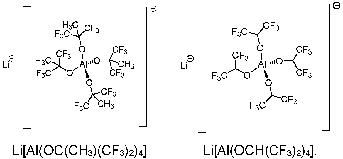
- Um die Leitfähigkeit und/oder weitere Eigenschaften des Elektrolyten an einen gewünschten Wert anzupassen, weist der Elektrolyt in einer weiteren vorteilhaften Ausgestaltung der erfindungsgemäßen wiederaufladbaren Batteriezelle zumindest ein zweites, von dem ersten Leitsalz nach Formel (I) abweichendes Leitsalz auf. Das bedeutet, dass der Elektrolyt neben dem ersten Leitsalz ein oder auch weitere zweite Leitsalze enthalten kann, die sich in ihrer chemischen Zusammensetzung sowie ihrer chemischen Struktur von dem ersten Leitsalz unterscheiden.
- In einer weiteren vorteilhaften Ausgestaltung der erfindungsgemäßen wiederaufladbaren Batteriezelle ist das zweite Leitsalz eine Alkalimetallverbindung, insbesondere eine Lithiumverbindung. Die Alkalimetallverbindung oder die Lithiumverbindung sind ausgewählt aus der Gruppe, die gebildet wird von einem Aluminat, einem Halogenid, einem Oxalat, einem Borat, einem Phosphat, einem Arsenat und einem Gallat. Vorzugsweise ist das zweite Leitsalz ein Lithiumtetrahalogenoaluminat, insbesondere LiAlCl4.
- Des Weiteren enthält der Elektrolyt in einer weiteren vorteilhaften Ausgestaltung der erfindungsgemäßen wiederaufladbaren Batteriezelle zumindest ein Additiv. Dieses Additiv ist vorzugsweise ausgewählt aus der Gruppe, die gebildet wird von Vinylencarbonat und seinen Derivaten, Vinylethylencarbonat und seinen Derivaten, Methylethylencarbonat und seinen Derivaten, Lithium(bisoxalato)borat, Lithiumdifluor(oxalato)borat, Lithiumtetraf-luor(oxalato)phosphat, Lithiumoxalat, 2-Vinylpyridin, 4-Vinylpyridin, cyclische Exomethylencarbonate, Sultone, cyclische und acyclische Sulfonate, acyclische Sulfite, cyclische und acyclische Sulfinate, organische Ester anorganischer Säuren, acyclische und cyclische Alkane, welche acyclischen und cyclischen Alkane einen Siedepunkt bei 1 bar von mindestens 36 °C aufweisen, aromatische Verbindungen, halogenierte cyclische und acyclische Sulfonylimide, halogenierte cyclische und acyclische Phosphatester, halogenierte cyclische und acyclische Phosphine, halogenierte cyclische und acyclische Phosphite, halogenierte cyclische und acyclische Phosphazene, halogenierte cyclische und acyclische Silylamine, halogenierte cyclische und acyclische halogenierte Ester, halogenierte cyclische und acyclische Amide, halogenierte cyclische und acyclische Anhydride und halogenierte organische Heterocyclen.
Bezogen auf das Gesamtgewicht der Elektrolytzusammensetzung weist der Elektrolyt in einer weiteren vorteilhaften Weiterbildung der wiederaufladbaren Batteriezelle folgende Zusammensetzung auf: - (i) 5 bis 99,4 Gew.-% Schwefeldioxid,
- (ii) 0,6 bis 95 Gew.-% des ersten Leitsalzes,
- (iii) 0 bis 25 Gew.-% des zweiten Leitsalzes und
- (iv) 0 bis 10 Gew.-% des Additivs.
- Wie bereits zuvor erwähnt, kann der Elektrolyt nicht nur ein erstes Leitsalz nach Formel (I) und ein zweites Leitsalz enthalten, sondern jeweils auch mehrere erste Leitsalze nach Formel (I) und mehrere zweite Leitsalze. Die zuvor genannten prozentualen Anteile schließen im letztgenannten Fall auch mehrere erste Leitsalze und mehrere zweite Leitsalze ein. Die Stoffmengenkonzentration des ersten Leitsalzes liegt im Bereich von 0,01 mol/l bis 10 mol/l, bevorzugt von 0,05 mol/l bis 10 mol/l, weiter bevorzugt von 0,1 mol/l bis 6 mol/l und besonders bevorzugt von 0,2 mol/l bis 3,5 mol/l bezogen auf das Gesamtvolumen des Elektrolyten.
Eine weitere vorteilhafte Weiterbildung der erfindungsgemäßen wiederaufladbaren Batteriezelle sieht vor, dass der Elektrolyt mindestens 0,1 Mol SO2, bevorzugt mindestens 1 Mol SO2, weiter bevorzugt mindestens 5 Mol SO2, weiter bevorzugt mindestens 10 Mol SO2 und besonders bevorzugt mindestens 20 Mol SO2 je Mol Leitsalz enthält. Der Elektrolyt kann auch sehr hohe molare Anteile an SO2 enthalten, wobei der bevorzugte obere Grenzwert mit 2600 Mol SO2 je Mol Leitsalz angegeben werden kann und Obergrenzen von 1500, 1000, 500 und 100 Mol SO2 je Mol Leitsalz in dieser Reihenfolge weiter bevorzugt sind. Der Begriff "je Mol Leitsalz" bezieht sich dabei auf alle Leitsalze, die im Elektrolyten enthalten sind. Auf SO2-basierende Elektrolyte mit einem derartigen Konzentrationsverhältnis zwischen SO2 und dem Leitsalz haben den Vorteil, dass sie im Vergleich zu den aus dem Stand der Technik bekannten Elektrolyten, welche beispielsweise auf einem organischen Lösungsmittelgemisch basieren, eine größere Menge an Leitsalz lösen können. Im Rahmen der Erfindung wurde festgestellt, dass überraschenderweise ein Elektrolyt mit einer relativ geringen Konzentration an Leitsalz trotz des damit verbundenen höheren Dampfdrucks vorteilhaft ist, insbesondere hinsichtlich dessen Stabilität über viele Lade- und Entladezyklen der wiederaufladbaren Batteriezelle. Die Konzentration an SO2 im Elektrolyten wirkt sich auf dessen Leitfähigkeit aus. Somit kann durch die Wahl der SO2-Konzentration die Leitfähigkeit des Elektrolyten an die geplante Verwendung einer mit diesem Elektrolyten betriebenen wiederaufladbaren Batteriezelle angepasst werden. Der Gesamtgehalt von SO2 und dem ersten Leitsalz kann größer als 50 Gewichtsprozent (Gew%) des Gewichts des Elektrolyten sein, bevorzugt größer als 60 Gew%, weiter bevorzugt größer als 70 Gew%, weiter bevorzugt größer als 80 Gew%, weiter bevorzugt größer als 85 Gew%, weiter bevorzugt größer als 90 Gew%, weiter bevorzugt größer als 95 Gew% oder weiter bevorzugt größer als 99 Gew%. - Der Elektrolyt kann mindestens 5 Gew% SO2 bezogen auf die Gesamtmenge des in der wiederaufladbaren Batteriezelle enthaltenen Elektrolyten enthalten, wobei Werte von 20 Gew% SO2, 40 Gew% SO2 und 60 Gew% SO2 weiter bevorzugt sind. Der Elektrolyt kann auch bis zu 95 Gew% SO2 enthalten, wobei Maximalwerte von 80 Gew% SO2 und 90 Gew% SO2 in dieser Reihenfolge bevorzugt sind.
Es liegt im Rahmen der Erfindung, dass der Elektrolyt vorzugsweise einen nur geringen oder sogar gar keinen prozentualen Anteil an zumindest einem organischen Lösungsmittel aufweist. Vorzugsweise kann der Anteil an organischen Lösungsmitteln im Elektrolyten, welche beispielsweise in Form eines oder einer Mischung mehrerer Lösungsmittel vorhanden ist, höchstens 50 Gew% des Gewichts des Elektrolyten betragen. Besonders bevorzugt sind geringere Anteile von höchstens 40 Gew%, von höchstens 30 Gew%, von höchstens 20 Gew%, von höchstens 15 Gew%, von höchstens 10 Gew%, von höchstens 5 Gew% oder von höchstens 1 Gew% des Gewichts des Elektrolyten. Weiter bevorzugt ist der Elektrolyt frei von organischen Lösungsmitteln. Durch den nur geringen Anteil an organischen Lösungsmitteln oder sogar deren vollständige Abwesenheit ist der Elektrolyt entweder kaum oder gar nicht brennbar. Dies erhöht die Betriebssicherheit einer mit einem derartigen auf SO2-basierenden Elektrolyten betriebenen wiederaufladbaren Batteriezelle. Besonders bevorzugt ist der auf SO2-basierende Elektrolyt im Wesentlichen frei von organischen Lösungsmitteln.
Bezogen auf das Gesamtgewicht der Elektrolytzusammensetzung weist der Elektrolyt in einer weiteren vorteilhaften Weiterbildung der wiederaufladbaren Batteriezelle folgende Zusammensetzung auf: - (i) 5 bis 99,4 Gew.-% Schwefeldioxid,
- (ii) 0,6 bis 95 Gew.-% des ersten Leitsalzes,
- (iii) 0 bis 25 Gew.-% des zweiten Leitsalzes,
- (iv) 0 bis 10 Gew.-% des Additivs und
- (v) 0 bis 50 Gew.-% eines organischen Lösungsmittels.
- Nachfolgend sind vorteilhafte Weiterbildungen der erfindungsgemäßen wiederaufladbaren Batteriezelle im Hinblick auf das aktive Metall beschrieben:
In einer vorteilhaften Weiterbildung der wiederaufladbare Batteriezelle ist das aktive Metall - ein Alkalimetall, insbesondere Lithium oder Natrium;
- ein Erdalkalimetall, insbesondere Calcium;
- ein Metall der Gruppe 12 des Periodensystems, insbesondere Zink; oder
- Aluminium.
- Nachfolgend sind vorteilhafte Weiterbildungen der erfindungsgemäßen wiederaufladbaren Batteriezelle im Hinblick auf die negative Elektrode beschrieben:
Eine weitere vorteilhafte Weiterbildung der wiederaufladbaren Batteriezelle sieht vor, dass die negative Elektrode eine Insertionselektrode ist. Diese Insertionselektrode enthält ein Insertionsmaterial als aktives Material, in welches die Ionen des aktiven Metalls während des Ladens der wiederaufladbare Batteriezelle eingelagert und aus welchem die Ionen des aktiven Metalls während des Entladens der wiederaufladbaren Batteriezelle ausgelagert werden können. Das bedeutet, dass sich die Elektrodenprozesse nicht nur an der Oberfläche der negativen Elektrode, sondern auch im Inneren der negativen Elektrode abspielen können. Wird beispielsweise ein Leitsalz auf Lithium-Basis verwendet, so können Lithiumionen während des Ladens der wiederaufladbaren Batteriezelle in das Insertionsmaterial eingelagert und während des Entladens der wiederaufladbare Batteriezelle aus diesem ausgelagert werden. Vorzugsweise enthält die negative Elektrode als aktives Material bzw. Insertionsmaterial Kohlenstoff, insbesondere in der Modifikation Graphit. Es liegt jedoch auch im Rahmen der Erfindung, dass der Kohlenstoff in Form von Naturgraphit (Flocken-Fördermittel oder gerundet), synthetischem Graphit (Mesophasen Graphit), graphitiertem MesoCarbon MicroBeads (MCMB), mit kohlenstoffbeschichtetem Graphit oder amorphem Kohlenstoff vorliegt.
Die negative Elektrode umfasst in einer weiteren vorteilhaften Weiterbildung der erfindungsgemäßen wiederaufladbaren Batteriezelle Lithium-Interkalations-Anodenaktivmaterialien, die keinen Kohlenstoff enthalten, so zum Beispiel Lithium-Titanate (z.B. Li4Ti5O12). - Eine weitere vorteilhafte Weiterbildung der erfindungsgemäßen wiederaufladbaren Batteriezelle sieht vor, dass die negative Elektrode mit Lithium Legierungsbildende-Anodenaktivmaterialien umfasst. Das sind zum Beispiel Lithium-speichernde Metalle und Metalllegierungen (z.B. Si, Ge, Sn, SnCoxCy, SnSix und dergleichen) und Oxide der Lithium-speichernden Metalle und Metalllegierungen (z.B. SnOx, SiOx, oxidische Gläser von Sn, Si und dergleichen).
- Die negative Elektrode enthält in einer weiteren vorteilhaften Weiterbildung der erfindungsgemäßen wiederaufladbaren Batteriezelle Konversions-Anodenaktivmaterialien. Diese Konversions-Anodenaktivmaterialien können beispielsweise Übergangsmetalloxide in Form von Manganoxiden (MnOx), Eisenoxiden (FeOx), Cobaltoxiden (CoOx), Nickeloxiden (NiOx), Kupferoxiden (CuOx) oder Metallhydride in Form von Magnesiumhydrid (MgH2), Titanhydrid (TiH2), Aluminiumhydrid (AlH3) und Bor-, Aluminium- und Magnesiumbasierte ternäre Hydride und dergleichen sein.
In einer weiteren vorteilhaften Weiterbildung der erfindungsgemäßen wiederaufladbaren Batteriezelle umfasst die negative Elektrode ein Metall, insbesondere metallisches Lithium. - Eine weitere vorteilhafte Weiterbildung der erfindungsgemäßen wiederaufladbaren Batteriezelle sieht vor, dass die negative Elektrode porös ist, wobei die Porosität bevorzugt höchstens 50 %, weiter bevorzugt höchstens 45 %, weiter bevorzugt höchstens 40 %, weiter bevorzugt höchstens 35 %, weiter bevorzugt höchstens 30 %, weiter bevorzugt höchstens 20 % und besonders bevorzugt höchstens 10 % beträgt. Die Porosität stellt das Hohlraumvolumen zu Gesamtvolumen der negativen Elektrode dar, wobei das Hohlraumvolumen von sogenannten Poren bzw. Hohlräumen ausgebildet wird. Diese Porosität führt zu einer Vergrößerung der inneren Oberfläche der negativen Elektrode. Weiterhin verringert die Porosität die Dichte der negativen Elektrode und damit auch ihr Gewicht. Die einzelnen Poren der negativen Elektrode können im Betrieb vorzugsweise vollständig mit dem Elektrolyten gefüllt sein.
Eine weitere vorteilhafte Weiterbildung der erfindungsgemäßen Batteriezelle sieht vor, dass die negative Elektrode ein Ableitelement aufweist. Das bedeutet, dass die negative Elektrode neben dem aktiven Material bzw. Insertionsmaterial auch ein Ableitelement umfasst. Dieses Ableitelement dient dazu, den erforderlichen elektronisch leitenden Anschluss des aktiven Materials der negativen Elektrode zu ermöglichen. Hierfür steht das Ableitelement in Kontakt mit dem an der Elektrodenreaktion der negativen Elektrode beteiligten aktiven Material. Dieses Ableitelement kann planar in Form eines dünnen Metallblechs oder einer dünnen Metallfolie ausgebildet sein. Die dünne Metallfolie weist vorzugsweise eine durchbrochene bzw. netzartige Struktur auf. Das planare Ableitelement kann auch aus einer mit Metall beschichtetet Kunststofffolie bestehen. Diese Metallbeschichtungen weisen eine Dicke im Bereich von 0,1 µm bis 20µm auf. Das aktive Material der negativen Elektrode ist vorzugsweise auf die Oberfläche des dünnen Metallblechs, der dünnen Metallfolie oder der mit Metall beschichteten Kunststofffolie aufgebracht. Das aktive Material kann auf der Vorder- und/oder der Rückseite des planaren Ableitelements aufgebracht sein. Derartige planare Ableitelemente weisen eine Dicke im Bereich von 5 µm bis 50 µm auf. Eine Dicke des planaren Ableitelements im Bereich von 10 µm bis 30 µm ist bevorzugt. Bei der Verwendung von planaren Ableitelementen kann die negative Elektrode eine Gesamtdicke von mindestens 20 µm, bevorzugt mindestens 40 µm und besonders bevorzugt mindestens 60 µm aufweisen. Die maximalen Dicke beträgt höchstens 200 µm, bevorzugt höchstens 150 µm und besonders bevorzugt höchstens 100 µm. Die flächenspezifische Kapazität der negativen Elektrode bezogen auf die Beschichtung einer Seite weist bei der Verwendung eines planaren Ableitelements vorzugsweise mindestens 0,5 mAh/cm2 auf, wobei folgende Werte in dieser Reihenfolge weiter bevorzugt sind: 1 mAh/cm2, 3 mAh/cm2, 5 mAh/cm2, 10 mAh/cm2, 15 mAh/cm2, 20 mAh/cm2. Weiterhin besteht auch die Möglichkeit, dass das Ableitelement dreidimensional in Form einer porösen Metallstruktur, insbesondere in Form eines Metallschaums ausgebildet sein kann. Der Begriff "dreidimensionale poröse Metallstruktur" bezeichnet dabei jede aus Metall bestehende Struktur, die sich nicht nur wie das dünne Metallblech bzw. die Metallfolie über Länge und Breite der flächigen Elektrode erstreckt, sondern auch über deren Dickendimension. Die dreidimensionale poröse Metallstruktur ist derartig porös, dass das aktive Material der negativen Elektrode in die Poren der Metallstruktur eingearbeitet werden kann. Bei der Menge an eingearbeitetem bzw. aufgebrachten aktivem Material handelt es sich um die Beladung der negativen Elektrode. Wenn das Ableitelement dreidimensional in Form einer porösen Metallstruktur, insbesondere in Form eines Metallschaums ausgebildet ist, dann weist die negative Elektrode vorzugsweise eine Dicke von mindestens 0,2 mm, bevorzugt mindestens 0,3 mm, weiter bevorzugt mindestens 0,4 mm, weiter bevorzugt mindestens 0,5 mm und besonders bevorzugt mindestens 0,6 mm auf. Die Dicke der Elektroden ist in diesem Fall deutlich größer im Vergleich zu negativen Elektroden, welche bei organischen Lithium-Ionen-Zellen Anwendung finden. Eine weitere vorteilhafte Ausgestaltung sieht vor, dass die flächenspezifische Kapazität der negativen Elektrode bei der Verwendung eines dreidimensionalen Ableitelements, insbesondere in Form eines Metallschaums vorzugsweise mindestens 2,5 mAh/cm2 beträgt, wobei folgende Werte in dieser Reihenfolge weiter bevorzugt sind: 5 mAh/cm2, 15 mAh/cm2, 25 mAh/cm2, 35 mAh/cm2, 45 mAh/cm2, 55 mAh/cm2, 65 mAh/cm2, 75 mAh/cm2. Wenn das Ableitelement dreidimensional in Form einer porösen Metallstruktur, insbesondere in Form eines Metallschaums ausgebildet ist, beträgt die Menge des aktiven Materials der negativen Elektrode, d.h. die Beladung der Elektrode, bezogen auf ihre Fläche, mindestens 10 mg/cm2, bevorzugt mindestens 20 mg/cm2, weiter bevorzugt mindestens 40 mg/cm2, weiter bevorzugt mindestens 60 mg/cm2, weiter bevorzugt mindestens 80 mg/cm2 und besonders bevorzugt mindestens 100 mg/cm2. Diese Beladung der negativen Elektrode wirkt sich positiv auf den Ladevorgang sowie den Entladevorgang der wiederaufladbaren Batteriezelle aus. - Die negative Elektrode weist in einer weiteren vorteilhaften Weiterbildung der erfindungsgemäßen Batteriezelle zumindest ein Bindemittel auf. Dieses Bindemittel ist vorzugsweise ein fluoriertes Bindemittel, insbesondere ein Polyvinylidenfluorid und/oder ein Terpolymer, das aus Tetrafluorethylen, Hexafluorpropylen und Vinylidenfluorid ausgebildet ist. Es kann jedoch auch ein Bindemittel sein, welches aus einem Polymer besteht, das aus monomeren Struktureinheiten einer konjugierten Carbonsäure oder aus dem Alkali-, Erdalkali- oder Ammoniumsalz dieser konjugierten Carbonsäure oder aus einer Kombination daraus aufgebaut ist. Weiterhin kann das Bindemittel auch aus einem Polymer bestehen, das auf monomeren Styrol- und Butadien-Struktureinheiten basiert. Außerdem kann das Bindemittel auch ein Bindemittel aus der Gruppe der Carboxymethylcellulosen sein. Das Bindemittel liegt in der negativen Elektrode vorzugsweise in einer Konzentration von höchstens 20 Gew%, weiter bevorzugt höchstens 15 Gew%, weiter bevorzugt höchstens 10 Gew%, weiter bevorzugt höchstens 7 Gew%, weiter bevorzugt höchstens 5 Gew% und besonders bevorzugt höchstens 2 Gew% bezogen auf das Gesamtgewicht der negativen Elektrode vor.
Die negative Elektrode weist in einer weiteren vorteilhaften Weiterbildung der erfindungsgemäßen Batteriezelle zumindest ein Leitfähigkeitsadditiv auf. Das Leitfähigkeitsadditiv sollte bevorzugt ein geringes Gewicht, eine hohe chemische Beständigkeit und eine hohe spezifische Oberfläche aufweisen, Beispiele für Leitfähigkeitsadditive sind partikulärer Kohlenstoff (carbon black, Super P, acetylen black), faserartiger Kohlenstoff (CarbonNanoTtubes CNT, Kohelnstoff(nano)fasern), feinverteilte Graphite und Graphen(-Nanos-heets). - Aufbau der wiederaufladbaren Batteriezelle
Nachfolgend sind vorteilhafte Weiterbildungen der erfindungsgemäßen wiederaufladbaren Batteriezelle im Hinblick auf deren Aufbau beschrieben:
Um die Funktion der wiederaufladbaren Batteriezelle weiter zu verbessern, sieht eine weitere vorteilhafte Weiterbildung der erfindungsgemäßen wiederaufladbaren Batteriezelle vor, dass die wiederaufladbaren Batteriezelle mehrere negative Elektroden und mehrere Hochvoltelektroden umfasst, die alternierend gestapelt in dem Gehäuse angeordnet sind. - Hierbei sind die positiven Elektroden und die negativen Elektroden vorzugsweise jeweils durch Separatoren voneinander elektrisch getrennt.
Der Separator kann aus einem Vlies, einer Membran, einem Gewebe, einem Gewirke, einem organischen Material, einem anorganischen Material oder aus einer Kombination hiervon ausgebildet sein. Organische Separatoren können aus unsubstituierten Polyolefinen (z.B. Polypropylen oder Polyethylen), partiell bis vollständig halogensubstituierten Polyolefinen (z.B. partiell bis ganz fluorsubstituiert, insbesondere PVDF, ETFE, PTFE), Polyestern, Polyamiden oder Polysulfonen bestehen. Separatoren, die eine Kombination von organischen und anorganischen Materialien enthalten, sind zum Beispiel Glasfaser-Textilmaterialien, bei denen die Glasfasern mit einer geeigneten Polymeren Beschichtung versehen sind. Die Beschichtung enthält vorzugsweise ein fluorhaltiges Polymer wie beispielsweise Polytetrafluorethylen (PTFE), Ethylen-Tetrafluorethylen (ETFE), Perfluorethylenpropylen (FEP), THV (Terpolymer aus Tetrafluorethylen, Hexafluorethylen und Vinylidenfluorid), ein Perfluoralkoxy-Polymer (PFA), Aminosilan, Polypropylen oder Polyethylen (PE). Der Separator kann im Gehäuse der wiederaufladbaren Batteriezelle auch gefaltet vorliegen, beispielsweise in Form eines sogenannten "Z-Foldings". Bei diesem Z-Folding ist ein streifenförmiger Separator durch bzw. um die Elektroden z-artig gefaltet. Weiterhin kann der Separator auch als Separatorpapier ausgebildet sein.
Es liegt auch im Rahmen der Erfindung, dass der Separator als Umhüllung ausgebildet sein kann, wobei jede Hochvoltelektrode oder jede negative Elektrode von der Umhüllung umhüllt ist. Die Umhüllung kann aus einem Vlies, einer Membran, einem Gewebe, einem Gewirke, einem organischen Material, einem anorganischen Material oder aus einer Kombination hiervon ausgebildet sein.
Eine Umhüllung der positiven Elektrode führt zu einer gleichmäßigeren lonenwanderung und Ionenverteilung in der wiederaufladbaren Batteriezelle. Je gleichmäßiger die lonenverteilung, insbesondere in der negativen Elektrode ist, desto höher kann die mögliche Beladung der negativen Elektrode mit aktivem Material und infolgedessen die nutzbare Kapazität der wiederaufladbaren Batteriezelle sein. Gleichzeitig werden Risiken vermieden, die mit einer ungleichmäßigen Beladung und einer daraus resultierenden Abscheidung des aktiven Metalls verbunden sein können. Diese Vorteile wirken sich vor allem aus, wenn die positiven Elektroden der wiederaufladbaren Batteriezelle mit der Umhüllung umhüllt sind.
Die Flächenmaße der Elektroden und der Umhüllung können vorzugsweise solcherart aufeinander abgestimmt sein, dass die Außenabmessungen der Umhüllung der Elektroden und die Außenabmessungen der nicht umhüllten Elektroden mindestens in einer Dimension übereinstimmen. - Die Flächenausdehnung der Umhüllung kann vorzugsweise größer als die Flächenausdehnung der Elektrode sein. In diesem Fall erstreckt sich die Umhüllung über eine Begrenzung der Elektrode hinaus. Zwei die Elektrode beidseitig bedeckende Schichten der Umhüllung können daher am Rand der positiven Elektrode durch eine Randverbindung miteinander verbunden werden.
In einer weiteren vorteilhaften Ausgestaltung der erfindungsgemäßen wiederaufladbaren Batteriezelle weisen die negativen Elektroden eine Umhüllung auf, während die positiven Elektroden keine Umhüllung haben. - Weitere vorteilhafte Eigenschaften der Erfindung werden nachfolgend anhand von Figuren, Beispielen und Experimenten näher beschrieben und erläutert.
- Figur 1:
- zeigt ein erstes Ausführungsbeispiel einer erfindungsgemäßen wiederaufladbaren Batteriezelle in einer Querschnittsdarstellung;
- Figur 2:
- zeigt eine elektronenmikroskopische Aufnahme der dreidimensionalen porösen Struktur des Metallschaums des ersten Ausführungsbeispiels aus Figur 1 als Detaildarstellung;
- Figur 3:
- zeigt ein zweites Ausführungsbeispiel einer erfindungsgemäßen wiederaufladbaren Batteriezelle in einer Querschnittsdarstellung;
- Figur 4:
- zeigt ein Detail des zweiten Ausführungsbeispiels aus
Figur 3 ; - Figur 5:
- zeigt ein drittes Ausführungsbeispiel der erfindungsgemäßen wiederaufladbaren Batteriezelle in einer Explosionsdarstellung;
- Figur 6:
- zeigt die Entladekapazität als Funktion der Zykelzahl von Test-Vollzellen, die Lithiumnickelmangancobaltoxid (NMC) der Zusammensetzung LiNi0.6Mn0.2Co0,2O2 (NMC622) und LiNi0.8Mn0.1Co0,1O2 (NMC811) als aktives Material der positiven Elektrode enthalten;
- Figur 7:
- zeigt die Entladekapazität als Funktion der Zykelzahl von Test-Vollzellen, die Lithiumcobaltoxid LiCoO2 (LCO) als aktives Material der positiven Elektrode enthalten, wobei eine Referenz- Test-Vollzelle mit dem Referenzelektrolyten befüllt ist und eine Test-Vollzelle mit dem Elektrolyten 1 befüllt ist;
- Figur 8:
- zeigt die Entladekapazität als Funktion der Zykelzahl von Test-Vollzellen, die Lithiumnickelmangancobaltoxid (NMC) der Zusammensetzung LiNi0.6Mn0.2Co0,2O2 (NMC622) als aktives Material der positiven Elektrode aufweisen, wobei eine Referenz-Test-Vollzelle mit dem Referenzelektrolyten befüllt ist und eine Test-Vollzelle mit dem erfindungsgemäßen Elektrolyten 1 befüllt ist;
- Figur 9:
- zeigt einen Potentialverlauf in Volt [V] als Funktion der prozentualen Ladung einer Test-Vollzelle mit Lithiumeisenphosphat LiFePO4 (LEP) als aktives Material der positiven Elektrode, wobei die Ladeschlussspannung 5 Volt beträgt;
- Figur 10:
- zeigt die Entladekapazität als Funktion der Zykelzahl von Test-Vollzellen, die Lithiumeisenphosphat LiFePO4 (LEP) als aktives Material der positiven Elektrode aufweisen, wobei das obere Potential schrittweise von 4,5 V auf 5,0 V erhöht wird;
- Figur 11:
- zeigt die Entladekapazität als Funktion der Zykelzahl einer Test-Vollzelle mit Lithiumeisenmanganphosphat Li(Fe0.3Mn0.7)Po4 als aktives Material der positiven Elektrode, wobei die Ladeschlussspannung 4,5 Volt beträgt;
- Figur 12:
- zeigt die Entladekapazität als Funktion der Zykelzahl einer Test-Vollzelle mit einem Metalloxid der Zusammensetzung Li1.16Mn0.61 Ni0.15Co0.16O2 als aktives Material der positiven Elektrode, wobei die Ladeschlussspannung 4,8 Volt beträgt;
- Figur 13:
- zeigt den Potentialverlauf in Volt als Funktion der prozentualen Ladung von Zyklus 1 und den Zyklus 2 einer Test-Vollzelle mit einem Metalloxid der Zusammensetzung Li1.16Mn0.61Ni0.15Co0.16O2 als aktives Material der positiven Elektrode;
- Figur 14:
- zeigt den Potentialverlauf in Volt als Funktion der Kapazität von dem Zyklus 1 und dem Zyklus 2 einer Testzelle mit Lithiumnickelmanganoxid der Zusammensetzung LiNi0.5Mn1,5O4 als aktives Material der positiven Elektrode;
- Figur 15:
- zeigt das Potential in [V] von drei Test-Vollzellen, die mit den Elektrolyten 1 und 3 aus Beispiel 2 und dem Referenzelektrolyten aus Beispiel 1 befüllt wurden, beim Laden einer negativen Elektrode als Funktion der Kapazität, die bezogen ist auf die theoretische Kapazität der negativen Elektrode, während einer Deckschichtbildung auf der negativen Elektrode.
- Figur 16:
- zeigt den Potentialverlauf bei der Entladung in Volt als Funktion der prozentualen Ladung von drei Test-Vollzellen, die mit den Elektrolyten 1, 3 und 4 aus Beispiel 2 befüllt wurden und Lithiumnickelmangancobaltoxid (NMC) als aktives Elektrodenmaterial enthielten;
- Figur 17:
- zeigt die Leitfähigkeit in [mS/cm] des Elektrolyten 1 aus Beispiel 2 in Abhängigkeit von der Konzentration der Verbindung 1;
- Figur 18:
- zeigt die Leitfähigkeit in [mS/cm] des Elektrolyten 3 aus Beispiel 2 in Abhängigkeit von der Konzentration der Verbindung 3; und
- Figur 19:
- zeigt die Leitfähigkeit in [mS/cm] des Elektrolyten 4 aus Beispiel 2 in Abhängigkeit von der Konzentration der Verbindung 4;
-
Figur 1 zeigt ein erstes Ausführungsbeispiel einer erfindungsgemäßen wiederaufladbaren Batteriezelle 2 in Querschnittsdarstellung. Diese wiederaufladbare Batteriezelle 2 ist als prismatische Zelle ausgebildet und weist unter anderem ein Gehäuse 1 auf. Dieses Gehäuse 1 umschließt eine Elektrodenanordnung 3, die drei positive Elektroden 4 und vier negative Elektroden 5 umfasst. Die positiven Elektroden 4 und die negativen Elektroden 5 sind in der Elektrodenanordnung 3 alternierend gestapelt angeordnet. Die positive Elektrode 4 ist in diesem Ausführungsbeispiel als Hochvoltelektrode ausgebildet. Das Gehäuse 1 kann jedoch auch mehr positive Elektroden 4 in Form von Hochvoltelektroden und/oder negative Elektroden 5 aufnehmen. Generell ist es bevorzugt, wenn die Anzahl der negativen Elektroden 5 um eins größer als die Anzahl der positiven Elektroden 4 ist. Dies hat zur Folge, dass die äußeren Stirnflächen des Elektrodenstapels von den Elektrodenoberflächen der negativen Elektroden 5 gebildet werden. Die Elektroden 4, 5 sind über Elektrodenanschlüsse 6, 7 mit entsprechenden Anschlusskontakten 9, 10 der wiederaufladbaren Batteriezelle 2 verbunden. Die wiederaufladbare Batteriezelle 2 ist derart mit einem auf SO2-basierenden Elektrolyten gefüllt, dass der Elektrolyt möglichst vollständig in sämtliche Poren bzw. Hohlräume, insbesondere innerhalb der Elektroden 4, 5, eindringt. Der Elektrolyt ist inFigur 1 nicht sichtbar. Im vorliegenden Ausführungsbeispiel enthalten die positiven Elektroden 4 eine Interkalationsverbindung als aktives Material. Bei dieser Interkalationsverbindung handelt es sich um LiCoMnO4 mit einer Spinell-Struktur.
Die Elektroden 4, 5 sind im vorliegenden Ausführungsbeispiel flächig ausgebildet, d.h. als Schichten mit einem im Verhältnis zu ihrer Flächenausdehnung geringeren Dicke. Sie sind jeweils durch Separatoren 11 voneinander getrennt. Das Gehäuse 1 der wiederaufladbaren Batteriezelle 2 ist im Wesentlichen quaderförmig ausgebildet, wobei sich die Elektroden 4, 5 und die in Schnittdarstellung gezeigten Wände des Gehäuses 1 senkrecht zu der Zeichenebene erstrecken und im Wesentlichen gerade und eben geformt sind. Die wiederaufladbare Batteriezelle 2 kann jedoch auch als Wickelzelle ausgebildet sein, bei
welcher die Elektroden aus dünnen Lagen bestehen, die zusammen mit einem Separatormaterial aufgewickelt sind. Die Separatoren 11 trennen einerseits die positive Elektrode 4 und die negative Elektrode 5 räumlich und elektrisch und sind andererseits unter anderem für die Ionen des aktiven Metalls durchlässig. Auf diese Weise entstehen große elektrochemisch wirksame Oberflächen, die eine entsprechend hohe Stromausbeute ermöglichen.
Die Elektroden 4, 5 weisen weiterhin ein Ableitelement auf, welches dazu dient, den erforderlichen elektronisch leitenden Anschluss des aktiven Materials der jeweiligen Elektrode zu ermöglichen. Dieses Ableitelement steht in Kontakt zu dem an der Elektrodenreaktion der jeweiligen Elektrode 4, 5 beteiligten aktiven Material (inFigur 1 nicht dargestellt). Das Ableitelement ist in Form eines porösen Metallschaums 18 ausgebildet. Der Metallschaum 18 erstreckt sich über die Dickendimension der Elektroden 4, 5. Das aktive Material der positiven Elektroden 4 und der negativen Elektroden 5 ist jeweils in die Poren dieses Metallschaums 18 eingearbeitet, sodass es dessen Poren über die gesamte Dicke der Metallstruktur gleichmäßig füllt. Zur Verbesserung der mechanischen Festigkeit enthalten die positiven Elektroden 4 ein Bindemittel. Bei diesem Bindemittel handelt es sich um ein Fluorpolymer. Die negativen Elektroden 5 enthalten als aktives Material Kohlenstoff in einer als Insertionsmaterial zur Aufnahme von Lithiumionen geeigneten Form. Die Struktur der negativen Elektrode 5 ist ähnlich wie bei der positiven Elektrode 4. -
Figur 2 zeigt eine elektronenmikroskopische Aufnahme der dreidimensionalen porösen Struktur des Metallschaums 18 des ersten Ausführungsbeispiels ausFigur 1 . Anhand des angegebenen Maßstabes ist zu erkennen, dass die Poren P im Mittel einen Durchmesser von mehr als 100 µm haben, also verhältnismäßig groß sind. Bei diesem Metallschaum handelt es sich um einen Metallschaum aus Nickel. -
Figur 3 zeigt ein zweites Ausführungsbeispiel einer erfindungsgemäßen wiederaufladbaren Batteriezelle 20 in Querschnittsdarstellung. Dieses zweite Ausführungsbeispiel unterscheidet sich von dem inFigur 1 gezeigten, ersten Ausführungsbeispiel dadurch, dass die Elektrodenanordnung eine positive Elektrode 23 und zwei negative Elektroden 22 umfasst. Sie sind jeweils durch Separatoren 21 voneinander getrennt und von einem Gehäuse 28 umgeben. Die positive Elektrode 23 weist ein Ableitelement 26 in Form einer planaren Metallfolie auf, auf welche das aktive Material 24 der positiven Elektrode 23 beidseitig aufgebracht ist. Die negativen Elektroden 22 umfassen ebenfalls ein Ableitelement 27 in Form einer planaren Metallfolie, auf welche das aktive Material 25 der negativen Elektrode 22 beidseitig aufgebracht ist. Alternativ können die planaren Ableitelemente der Randelektroden, also der Elektroden, die den Elektrodenstapel abschließen, nur einseitig mit aktivem Material beschichtetet sein. Die nicht-beschichtete Seite zeigt zur Wand des Gehäuses 28. Die Elektroden 22, 23 sind über Elektrodenanschlüsse 29, 30 mit entsprechenden Anschlusskontakten 31, 32 der wiederaufladbaren Batteriezelle 20 verbunden. -
Figur 4 zeigt die planare Metallfolie, welche jeweils als Ableitelement 26, 27 für die positive Elektroden 23 und die negativen Elektroden 22 im zweiten Ausführungsbeispiel ausFigur 3 dient. Diese Metallfolie weist eine durchbrochene bzw. netzartige Struktur mit einer Dicke von 20 µm auf. -
Figur 5 zeigt ein drittes Ausführungsbeispiel einer erfindungsgemäßen wiederaufladbaren Batteriezelle 40 in Explosionsdarstellung. Dieses dritte Ausführungsbeispiel unterscheidet sich von den beiden zuvor erläuterten Ausführungsbeispielen dadurch, dass die positive Elektrode 44 von einer Umhüllung 13 umhüllt ist. Dabei ist eine Flächenausdehnung der Umhüllung 13 größer als eine Flächenausdehnung der positiven Elektrode 44, deren Begrenzung 14 inFigur 5 als gestrichelte Linie eingezeichnet ist. Zwei, die positive Elektrode 44 beidseitig bedeckende Schichten 15, 16 der Umhüllung 13 sind am umlaufenden Rand der positiven Elektrode 44 durch eine Randverbindung 17 miteinander verbunden. Die beiden negativen Elektroden 45 sind nicht umhüllt. Die Elektroden 44 und 45 können über die Elektrodenanschlüsse 46 und 47 kontaktiert werden. - Ein für die nachfolgend beschriebenen Beispiele verwendeter Referenzelektrolyt wurde nach dem in der
Patentschrift EP 2 954 588 B1 beschriebenen Verfahren hergestellt (im Nachfolgenden bezeichnet als [V7]). Zunächst wurde Lithiumchlorid (LiCI) unter Vakuum bei 120 °C für drei Tage getrocknet. Aluminiumpartikel (AI) wurden unter Vakuum für zwei Tage bei 450 °C getrocknet. LiCI, Aluminiumchlorid (AlCl3) und AI wurden in einem Molverhältnis AlCl3:LiCl:Al von 1:1,06:0,35 in einer Glasflasche mit einer Öffnung, die den Austritt von Gas ermöglicht, miteinander vermischt. Daraufhin wurde diese Mischung stufenweise zur Herstellung einer Salzschmelze wärmebehandelt. Nach dem Abkühlen wurde die gebildete Salzschmelze gefiltert, danach auf Raumtemperatur abgekühlt und letztlich SO2 zugeführt bis das gewünschte molare Verhältnis von SO2 zu LiAlCl4 gebildet wurde. Der so gebildete Referenzelektrolyt hatte die Zusammensetzung LiAlCl4 * x SO2, wobei x abhängig von der zugeführten Menge an SO2 ist. - Für die nachfolgend beschriebenen Experimente wurden vier Ausführungsbeispiele 1, 2, 3 und 4 des auf SO2-basierenden Elektrolyten hergestellt (nachfolgend bezeichnet als Elektrolyte 1, 2, 3 und 4). Hierfür wurden zunächst vier unterschiedliche erste Leitsalze nach Formel (I) gemäß einem in den folgenden Dokumenten [V8], [V9] und [V10] beschriebenen Herstellungsverfahren hergestellt:
- [V8] "I. Krossing, Chem. Eur. J. 2001, 7, 490;
- [V9] S. M. Ivanova et al., Chem. Eur. J. 2001, 7, 503;
- [V10] Tsujioka et al., J. Electrochem. Soc., 2004, 151, A1418"
- Diese vier unterschiedlichen, ersten Leitsalze nach Formel (I) werden nachfolgend als Verbindungen 1, 2, 3 und 4 bezeichnet. Sie stammen aus der Familie der Polyfluoroalkoxyaluminate und wurden gemäß folgender Reaktionsgleichung ausgehend von LiAlH4 und dem entsprechenden Alkohol R-OH mit R1=R2=R3=R4 in Hexan hergestellt.

- Hierdurch wurden die nachfolgend darstellten Verbindungen 1, 2, 3 und 4 mit den Summen- bzw. Strukturformeln gebildet:


- Zur Aufreinigung wurden die Verbindungen 1, 2, 3 und 4 zunächst umkristallisiert. Hierdurch wurden Reste des Edukts LiAlH4 aus dem ersten Leitsalz entfernt, da dieses Edukt möglicherweise mit eventuell vorhandenen Wasserspuren in SO2 zur Funkenbildung führen könnte.
Danach erfolgte die Lösung der Verbindungen 1, 2, 3 und 4 in SO2. Hierbei wurde herausgefunden, dass sich die Verbindungen 1, 2, 3 und 4 in SO2 gut lösen.
Die Herstellung der Elektrolyte 1, 2, 3 und 4 wurde bei Tieftemperatur oder unter Druck gemäß den nachfolgend aufgelisteten Verfahrensschritten 1 bis 4 durchgeführt: - 1) Vorlage der jeweiligen Verbindung 1, 2, 3 und 4 in jeweils einem Druckkolben mit Steigrohr,
- 2) Evakuieren der Druckkolben,
- 3) Einströmen von flüssigem SO2 und
- 4) Wiederholung der Schritte 2 + 3 bis die Zielmenge an SO2 zugegeben worden ist.
- Die jeweilige Konzentration der Verbindungen 1, 2, 3 und 4 in den Elektrolyten 1, 2, 3 und 4 betrug 0,6 mol/l (Stoffmengenkonzentration bezogen auf 1 Liter des Elektrolyten), sofern in der Experimentbeschreibung nichts Anderes beschrieben ist. Mit den Elektrolyten 1, 2, 3 und 4 und dem Referenzelektrolyten wurden die nachfolgend beschriebenen Experimente durchgeführt.
- Die in den nachfolgend beschriebenen Experimenten verwendeten Test-Vollzellen sind wiederaufladbare Batteriezellen mit zwei negativen Elektroden und einer positiven Elektrode, welche jeweils durch einen Separator getrennt waren. Die positiven Elektroden wiesen ein aktives Material, einen Leitfähigkeitsvermittler und ein Bindemittel auf. Die negativen Elektroden enthielten Graphit als aktives Material und ebenfalls ein Bindemittel. Wie im Experiment erwähnt, können die negativen Elektroden auch ein Leitfähigkeitsadditiv enthalten. Das aktive Material der positiven Elektrode ist im jeweiligen Experiment benannt. Das Ableitelement der positiven und der negativen Elektrode bestand aus Nickel. Unter anderem ist das Ziel der Untersuchungen, die Verwendung von verschiedenen aktiven Materialien für die positive Elektrode in einer erfindungsgemäßen Batteriezelle mit einem hohen oberen Potential (Ladepotential) zu bestätigen. Tabelle 3 zeigt, welche aktiven Materialien der Hochvoltelektrode untersucht wurden und welche oberen Potentiale dabei verwendet wurden.
- Die Test-Vollzellen wurden jeweils mit dem für die Experimente benötigten Elektrolyten, d. h. entweder mit dem Referenzelektrolyten oder den Elektrolyten 1, 2, 3 oder 4 befüllt.
Für jedes Experiment wurden mehrere, d.h. zwei bis vier identische Test-Vollzellen hergestellt. Die in den Experimenten vorgestellten Ergebnisse sind jeweils Mittelwerte aus den für die identischen Test-Vollzellen erhaltenen Messwerte.Tabelle 3: Untersuchte aktive Materialien Experiment Aktives Material Oberes Potential 1 Lithiumnickelmangancobaltoxid (NMC) der Zusammensetzung 4,4 V LiNi0.6Mn0.2Co0,2O2 (NMC622) und LiNi0.8Mn0.1Co0,1O2 4,6 V (NMC811) 5,0 V 2 Lithiumcobaltoxid LiCoO2 (LCO) 4,4 V 3 Lithiumnickelmangancobaltoxid (NMC) der Zusammensetzung 4,4 V LiNi0.6Mn0.2Co0,2O2 (NMC622) 4 Lithiumeisenphosphat LiFePO4 (LEP) 4,5-5,0 V 5 Lithiumeisenmanganphosphat Li(Fe0.3Mn0.7)PO4 4,5 V 6 Lithium-Mangan-reiches Metalloxid der Zusammensetzung 4,8 V Li1.16Mn0.61Ni0.15Co0.16O2 7 Lithiumnickelmanganoxid der Zusammensetzung 5,0 V LiNi0,5Mn1,5O4 - Bei Messungen in Test-Vollzellen wird z.B. die Entladekapazität über die Zykelzahl bestimmt werden. Dazu werden die Test-Vollzellen mit einer bestimmten Ladestromstärke bis zu einem bestimmten oberen Potential geladen. Das entsprechende obere Potential wird so lange gehalten, bis der Ladestrom auf einen bestimmten Wert abgesunken ist. Danach erfolgt die Entladung mit einer bestimmten Entladestromstärke bis zu einem bestimmten Entladepotential. Bei dieser Lademethode spricht man von einer sogenannten I/U-Ladung. Dieser Vorgang wird je nach gewünschter Zykelzahl wiederholt. Die oberen Potentiale bzw. das Entladepotential und die jeweiligen Lade- bzw. Entladestromstärken sind in den Experimenten benannt. Auch der Wert, auf den der Ladestrom abgesunken sein muss, ist in den Experimenten beschrieben. Der Begriff "oberes Potential" wird Synonym zu den Begriffen "Ladepotential" "Ladespannung", Ladeschlussspannung" und "obere Potentialgrenze" verwendet. Die Begriffe bezeichnen die Spannung/das Potential, bis zu welchem eine Zelle oder Batterie mit Hilfe einer Batterieladevorrichtung geladen wird. Bevorzugt erfolgt die Ladung der Test-Vollzellen mit einer Stromrate von C/2 und bei einer Temperatur von 22°C. Mit einer Lade- bzw. Entladerate von 1C wird definitionsgemäß die Nennkapazität einer Zelle in einer Stunde ge- bzw. entladen. Eine Laderate von C/2 bedeutet demnach eine Ladezeit von 2 Stunden.
Der Begriff "Entladepotential" wird Synonym zum Begriff "untere Zellspannung" verwendet. Damit wird die Spannung bzw. das Potential bezeichnet, bis zu welchem eine Zelle oder Batterie mit Hilfe einer Batterieladevorrichtung entladen wird. Bevorzugt erfolgt die Entladung der Batterie mit einer Stromrate von C/2 und bei einer Temperatur von 22°C. Die Entladekapazität wird aus dem Entladestrom und der Zeit, bis die Kriterien zur Beendigung der Entladung erfüllt sind, erhalten. Die dazugehörigen Figuren zeigen Mittelwerte für die Entladekapazitäten als Funktion der Zykelzahl. Diese Mittelwerte der Entladekapazitäten werden jeweils in Prozent der Nennkapazität ausgedrückt, oft normiert auf die maximale Kapazität, die im jeweiligen Versuch erreicht wurde. Die Nennkapazität wird erhalten, indem von der theoretischen Kapazität der positiven Elektrode diejenige Kapazität subtrahiert wird, die im ersten Zyklus für die Bildung einer Deckschicht auf der negativen Elektrode verbraucht wird. Diese Deckschicht wird beim ersten Laden der Test-Vollzelle auf der negativen Elektrode gebildet. Für diese Deckschichtbildung werden Lithiumionen irreversibel verbraucht, sodass der jeweiligen Test-Vollzelle weniger zykelbare Kapazität für die Folgezyklen zur Verfügung steht. - Mit positiven Elektroden aus Lithiumnickelmangancobaltoxid der Zusammensetzung LiNi0.6Mn0.2Co0,2O2 (NMC622) und LiNi0.8Mn0.1Co0,1O2 (NMC811) als aktive Elektrodenmaterialien wurde ein Experiment in Test-Vollzellen gemäß Beispiel 3 durchgeführt. Verbindungen der Zusammensetzung NMC können in einer Batteriezelle mit einem geeigneten Elektrolyten bis zu hohen oberen Potentialen geladen und wieder entladen werden. Die Test-Vollzellen wurden mit dem in Beispiel 2 beschriebenen Elektrolyten 1 befüllt.
Drei Test-Vollzellen enthielten Hochvoltelektroden mit der Verbindung NMC622, in einer Test-Vollzelle wurde NMC811 als aktives Hochvoltkathodenmaterial verwendet.
Zur Ermittlung der Entladekapazitäten (siehe Beispiel 4) wurden die Test-Vollzellen mit einer Stromstärke von 50 mA bis zu unterschiedlichen oberen Potentialen geladen. Das entsprechende obere Potential wurde so lange gehalten, bis der Ladestrom auf 40 mA abgesunken war. Danach erfolgte die Entladung mit einer Stromstärke von 50 mA bis zu einem Entladepotential von 2,5 Volt. Die oberen Potentiale lagen für die drei NMC622-Test-Vollzellen bei 4,4 Volt, bei 4,6 Volt bzw. bei 5,0 Volt. Das obere Potential der NMC811-Test-Vollzelle lag bei 4,6 Volt. -
Figur 6 zeigt Mittelwerte für die Entladekapazitäten der vier Test-Vollzellen als Funktion der Zykelzahl. Diese Mittelwerte der Entladekapazitäten werden jeweils in Prozent der Nennkapazität [% Nennkapazität] ausgedrückt. - Der Verlauf der Entladekapazitäten der vier Test-Vollzellen zeigt einen gleichmäßigen, leicht abnehmenden Verlauf. Die Kapazitätsabnahme ist etwas größer bei denjenigen Test-Vollzellen, die mit einem höheren oberen Potential gezykelt wurden.
- In der oben benannten Veröffentlichung [V3] aus dem Stand der Technik wurden ähnliche Experimente mit organischen Lithium-Ionen-Zellen mit NMC-Kathoden und dem organischen Elektrolyt LP57 durchgeführt, der die Zusammensetzung 1 M LiPF6 in EC:EMC 3:7 aufweist. Tabelle 4 vergleicht die Ergebnisse des Experiments 1 mit denen des Experiments aus der [V3]:
Tabelle 4: Vergleich der Ergebnisse von Experiment 1 mit dem Stand der Technik aus Dokument [V3] Oberes Potential: 4.4 V 4.6 V 5.0 V Entladekapazität [%] Zyklus 300 Entladekapazität [%] Zyklus 300 Entladekapazität [%] Zyklus 300 KathodenMaterial: St. d. Technik (organischer Elektrolyt; 1 M LiPF6 in EC:EMC 3:7) Erfindung Experiment 1 St. d. Technik (organischer Elektrolyt; 1 M LiPF6 in EC:EMC 3:7) Erfindung Experiment 1 St. d. Technik (organischer Elektrolyt; 1 M LiPF6 in EC:EMC 3:7) Erfindung Experiment 1 NMC (622) 94% 97% 39% 91% - 84% NMC (811) 66% - - 90% - - - Im Vergleich mit dem Stand der Technik werden die herausragenden Eigenschaften der erfindungsgemäßen Batteriezellen deutlich. Das Kathodenmaterial NMC(622) in Batteriezellen aus dem Stand der Technik zeigt bei einem oberen Potential von 4,4 Volt im 300. Zyklus nur eine Entladekapazität von 94% und bei einem oberen Potential von 4,6 Volt nur noch eine Entladekapazität von 39%. Im Vergleich dazu zeigt eine erfindungsgemäße Zelle mit NMC(622)-Kathodenmaterial bei 4,4 Volt eine Entladekapazität von 97% im 300. Zyklus, bei 4,6 Volt eine Entladekapazität von 91% und bei einem sehr hohen oberen Potential von 5,0 Volt sogar noch einen Wert von 84%.
- Das Kathodenmaterial NMC(811) zeigt in den Messungen aus dem Stand der Technik bei einem oberen Potential von 4,4 Volt eine Entladekapazität von 66% im 300. Zyklus. Das gleiche Material zeigt in einer erfindungsgemäßen Batteriezelle bei einem oberen Potential von 4,6 Volt noch eine hohe Entladekapazität von 90%.
- In einem weiteren Experiment wurden zwei Test-Vollzellen gemäß Beispiel 3 hergestellt. Das aktive Material der positiven Elektroden (Kathoden) bestand aus Lithiumcobaltoxid (LCO).
Eine erste Test-Vollzelle wurde für dieses Experiment 2 mit einem Referenzelektrolyten gemäß Beispiel 1 befüllt. Der Elektrolyt hatte die Zusammensetzung LiAlCl4*6 SO2. Die zweite Test-Vollzelle wurde mit dem in Beispiel 2 beschriebenen Elektrolyten 1 befüllt. Zur Ermittlung der Entladekapazitäten (siehe Beispiel 4) wurden die Test-Vollzellen entsprechend der Beschreibung in Experiment 1 gezykelt. Das obere Potential der Batteriezellen mit Referenzelektrolyt lag bei 4,2 Volt, das der erfindungsgemäßen Zellen bei 4,4 Volt.Figur 7 zeigt Mittelwerte für die Entladekapazitäten der zwei Test-Vollzellen als Funktion der Zykelzahl. Diese Mittelwerte der Entladekapazitäten werden jeweils in Prozent der Nennkapazität [% Nennkapazität] ausgedrückt. Der Verlauf der Entladekapazitäten der zwei Test-Vollzellen zeigt ein völlig unterschiedliches Verhalten.
Die Entladekapazität der Test-Vollzelle mit Referenzelektrolyt beginnt ab dem 45. Zyklus zu steigen und fällt dann ab dem 55. Zyklus steil ab, bis bei Zyklus 80 eine Kapazität von nur noch 50% erreicht wird. Diese Test-Vollzelle ist irreversibel geschädigt. Eine Batteriezelle, die eine Kombination aus einer Elektrode mit Lithiumcobaltoxid als aktivem Material und dem Referenzelektrolyt enthält, ist bei einem oberen Potential von 4,2 Volt nicht stabil.
Die erfindungsgemäße Zelle zeigt ein sehr stabiles Verhalten der Entladekapazität. Bei Zyklus 200 ist wird noch eine Kapazität von 97% erhalten. In der Messung musste aufgrund einer Gerätewartung zwischen Zyklus 125 und 126 eine Pause eingelegt werden. Die Kapazität nach der Pause war um 2 % erhöht, weswegen der Verlauf der Entladekapazität an dieser Stelle ein lokales Maximum aufweist. - Das Experiment 2 wurde mit Lithiumnickelmangancobaltoxid (NMC) der Zusammensetzung LiNi0.6Mn0.2Co0,2O2 (NMC622) als aktivem Material der positiven Elektroden (Kathoden) wiederholt. Es wurden wiederum zwei Test-Vollzellen gemäß Beispiel 3 hergestellt. Eine erste Test-Vollzelle wurde mit einem Referenzelektrolyten gemäß Beispiel 1 befüllt. Der Elektrolyt hatte die Zusammensetzung LiAlCl4*6 SO2. Die zweite Test-Vollzelle wurde mit dem in Beispiel 2 beschriebenen Elektrolyten 1 befüllt. Zur Ermittlung der Entladekapazitäten (siehe Beispiel 4) wurden die Test-Vollzellen entsprechend der Beschreibung in Experiment 1 gezykelt. Das obere Potential der ersten Test-Vollzelle mit Referenzelektrolyt lag bei 4,2 Volt, das der zweiten Test-Vollzelle bei 4,4 Volt.
Figur 8 zeigt Mittelwerte für die Entladekapazitäten dieser zwei Test-Vollzellen als Funktion der Zykelzahl. Diese Mittelwerte der Entladekapazitäten werden jeweils in Prozent der Nennkapazität [% Nennkapazität] ausgedrückt. Auch hier zeigt der Verlauf der Entladekapazitäten der zwei Test-Vollzellen ein völlig unterschiedliches Verhalten.
Die Entladekapazität der ersten Test-Vollzelle mit Referenzelektrolyt beginnt nach vorherigen Schwankungen ab dem 75. Zyklus stetig zu fallen. Bei Zyklus 130 wird eine Kapazität von nur noch 86% erreicht. Die erste Test-Vollzelle ist irreversibel geschädigt. Eine Batteriezelle, die eine Kombination aus einer Elektrode mit Lithiumnickelmangancobaltoxid (NMC) der Zusammensetzung LiNi0.6Mn0.2Co0,2O2 (NMC622) als aktivem Material und dem Referenzelektrolyt enthält, ist bei einem oberen Potential von 4,2 Volt nicht stabil. Die zweite Test-Vollzelle zeigt ein sehr stabiles Verhalten der Entladekapazität. Bei Zyklus 200 ist noch eine Kapazität von 97% erhalten. - Es wurde eine Test-Vollzelle gemäß Beispiel 3 mit Lithiumeisenphosphat LiFePO4 (LEP) als aktivem Elektrodenmaterial der positiven Elektrode hergestellt. Die Test-Vollzelle wurde mit dem in Beispiel 2 beschriebenen Elektrolyten 1 befüllt.
Figur 9 zeigt den Potentialverlauf in Volt [V] über der prozentualen Ladung, die auf die maximale Ladung der Test-Vollzelle bezogen ist [% der max. Ladung]. Die Test-Vollzelle wurde mit einer Stromstärke von 50 mA bis zu einem oberen Potential von 5 V geladen. Das Potential wurde so lange gehalten, bis der Ladestrom auf 40 mA abgesunken war. Danach erfolgte die Entladung mit einer Stromstärke von 50 mA bis zu einem Entladepotential von 2,5 Volt.
Das Lade-/ Entlade-Experiment wurde nochmals wiederholt, mit dem Unterschied, dass die obere Potentialgrenze bzw. die Ladeschlussspannung beim Laden von 4,5 Volt in 0,1 Volt-Schritten bis auf 5,0 Volt erhöht wurde (gestrichelte Linie). Mit jedem Potential wurden 5 Zyklen durchgeführt.Figur 10 zeigt die Entladekapazität (durchgezogene Linie) und die dazugehörigen Ladepotentiale (oberen Potentiale; gestrichelte Linie).
Die erreichten Entladekapazitäten sind für jedes Ladepotential nahezu identisch und liegen bei 99%. Das bedeutet, dass die erhaltenen Entladekapazitäten unabhängig vom Ladepotential sind. Ein höheres Ladepotential bedingt also keine unerwünschten Reaktionen, wie z.B. eine Zersetzung des Elektrolyten oder eine irreversible Zerstörung des aktiven Materials LEP. - Um weitere Lithiummetallphosphate als aktives Elektrodenmaterial zu testen, wurde in einem weiteren Experiment eine Test-Vollzelle gemäß Beispiel 3 hergestellt. Das aktive Material der positiven Elektroden (Kathoden) bestand aus Lithiumeisenmanganphosphat Li(Fe0.3Mn0.7)PO4.
Die Test-Vollzelle wurde mit dem in Beispiel 2 beschriebenen Elektrolyten 1 befüllt. Zur Ermittlung der Entladekapazitäten (siehe Beispiel 4) wurde die Test-Vollzelle entsprechend der Beschreibung in Experiment 1 gezykelt. Das obere Potential der Test-Vollzelle liegt bei 4,5 Volt.
Figur 11 zeigt Mittelwerte für die Entladekapazitäten der Test-Vollzelle als Funktion der Zykelzahl. Diese Mittelwerte der Entladekapazitäten werden jeweils in Prozent der Nennkapazität ausgedrückt. Die Test-Vollzelle zeigt ein sehr stabiles Verhalten der Entladekapazität. Bei Zyklus 200 ist wird noch eine Kapazität von 97% erhalten. - Um ein Metalloxid, welches reich an Lithium und Mangan ist, als aktives Elektrodenmaterial zu testen, wurde in einem weiteren Experiment eine Test-Vollzelle gemäß Beispiel 3 hergestellt. Das aktive Material der positiven Elektroden (Kathoden) bestand aus einem Metalloxid der Zusammensetzung Li1.16Mn0.61Ni0.15Co0.16O2, das reich an Lithium und Mangan ist. Die Test-Vollzelle wurde mit dem in Beispiel 2 beschriebenen Elektrolyten 1 befüllt. Zur Ermittlung der Entladekapazitäten (siehe Beispiel4) wurden die Test-Vollzelle mit einer Stromstärke von 100 mA bis zu einem oberen Potential von 4,8 Volt geladen. Das entsprechende obere Potential wurde so lange gehalten, bis der Ladestrom auf 40 mA abgesunken war. Danach erfolgte die Entladung mit einer Stromstärke von 100 mA bis zu einem Entladepotential von 2,0 Volt.
-
Figur 12 zeigt Mittelwerte für die Entladekapazitäten der Test-Vollzelle als Funktion der Zykelzahl. Diese Mittelwerte der Entladekapazitäten werden jeweils in Prozent der Nennkapazität ausgedrückt [% Nennkapazität]. Die Test-Vollzelle zeigt ein sehr stabiles Verhalten der Entladekapazität. Bei Zyklus 100 ist wird noch eine Kapazität von 90% erhalten.Figur 13 zeigt den Potentialverlauf in Volt [v] von Zyklus 1 und Zyklus 2 einer Test-Vollzelle mit einem Metalloxid, welches reich an Lithium und Mangan ist. Im ersten Zyklus wird das Metalloxid aktiviert, dadurch werden die für dieses Material typischen hohen spezifischen Kapazitäten ermöglicht. Der Potentialverlauf wird über der prozentualen Ladung dargestellt, die auf die maximale Ladung der Test-Vollzelle bezogen ist. Die Test-Vollzelle wurde mit einer Stromstärke von 100 mA bis zu einem oberen Potential von 4,8 V geladen. Das Potential wurde so lange gehalten, bis der Ladestrom auf 40 mA abgesunken war. Danach erfolgte die Entladung mit einer Stromstärke von 100 mA bis zu einem Entladepotential von 2,0 Volt. Der Potentialverlauf in Zyklus 1 zeigt ein deutlich anderes Verhalten, wie der Potentialverlauf in Zyklus 2. Das beruht auf der in der Literatur bekannten strukturellen Veränderung des Materials. Bei diesem Vorgang finden irreversible Veränderung des Materials statt, so dass es bei der Aktivierung im ersten Zyklus zu einem Verlust an aktiven Lithium-Ionen kommt. Es können nur noch weniger als 90% der Lithium-Ionen wieder in das Gitter eingelagert werden. InFigur 13 ist deutlich zu sehen, dass es im zweiten Zyklus zu einer Wiedereinlagerung von mehr als 90% kommt und damit die irreversiblen Verluste deutlich geringer sind als in der Literatur beschrieben. In Zyklus 2 zeigt sich besonders die hohe Potentialstabilität des Elektrolyten insofern, als dass bei einer oberen Ladeschlussspannung von 4,8V auch eine nahezu vollständige Interkalation der Lithium-Ionen im Zyklus 2 stattfindet. - Um ein Metalloxid mit einer Spinell-Struktur als aktives Elektrodenmaterial zu testen, wurde in einem weiteren Experiment eine Testzelle mit einer Drei-Elektrodenanordnung (Arbeitselektrode, Gegenelektrode und Bezugselektrode) hergestellt. Das aktive Material der positiven Elektrode (Kathoden) bestand aus einem Metalloxid der Zusammensetzung LiNi0,5Mn1,5O4. Die Gegenelektrode und die Bezugselektrode bestanden aus metallischem Lithium. Die Testzelle wurde mit dem in Beispiel 2 beschriebenen Elektrolyten 1 befüllt.
-
Figur 14 zeigt den Potentialverlauf der Zyklen 1 und 2 in Volt [V] als Funktion der Kapazität. Die Testzelle wurde mit einer Laderate von 0,1 C bis zu einem oberen Potential von 5 V geladen. Danach erfolgte die Entladung mit einer Entladerate von 0,1 C bis zu einem Entladepotential von 3,5 Volt. In beiden Zyklen ist trotz des hohen Ladeendpotentials von 5 Volt eine stabiles Lade- und Entladeverhalten. In Zyklus 1 wird eine hohe Kapazität von 154 mAh/g erreicht. Die Kapazität fällt in Zyklus 2 etwas ab. - Zur Untersuchung der Elektrolyte 1, 3 und 4 wurden verschiedene Experimente durchgeführt. Zum einen wurden die Deckschichtkapazitäten der Elektrolyte 1 und 3 und des Referenzelektrolyten ermittelt und zum anderen die Entladekapazitäten in den Elektrolyten 1, 3 und 4 bestimmt.
Zur Ermittlung der Deckschichtkapazität wurden drei Test-Vollen mit den in Beispiel 2 beschriebenen Elektrolyten 1 und 3 und dem in Beispiel 1 beschriebenen Referenzelektrolyten befüllt. Die drei Test-Vollzellen enthielten Lithiumeisenphosphat als Aktivmaterial der positiven Elektrode.
Figur 15 zeigt das Potenzial in Volt der Test-Vollzellen beim Laden der negativen Elektrode als Funktion der Kapazität, die bezogen ist auf die theoretische Kapazität der negativen Elektrode. Die zwei dargestellten Kurven zeigen gemittelte Ergebnisse jeweils mehrerer Experimente mit den vorstehend beschriebenen Test-Vollzellen. Zunächst wurden die Test-Vollzellen mit einem Strom von 15 mA geladen, bis eine Kapazität von 125 mAh (Qlad) erreicht war. Danach erfolgte die Entladung der Test-Vollzellen mit 15 mA bis zum Erreichen eines Potentials von 2,5 Volt. Dabei erfolgte die Ermittlung der Entladekapazität (Qent).
Die Kapazität in % der Theorie, die zur Bildung der Deckschicht auf der negativen Elektrode verbraucht wurde, berechnet sich gemäß nachfolgend genannter Formel:
Für die Entladeexperimente wurden drei Test-Vollzellen gemäß Beispiel 3 mit den in Beispiel 2 beschriebenen Elektrolyten 1, 3 und 4 befüllt. Die Test-Vollzellen hatten Lithiumnickelmangancobaltoxid (NMC) als aktives Material der positiven Elektrode. Zur Ermittlung der Entladekapazitäten (siehe Beispiel 4) wurden die Test-Vollzellen mit Stromstärke von 15 mA bis zu einer Kapazität von 125 mAh geladen. Danach erfolgte die Entladung mit einer Stromstärke von 15 mA bis zu einem Entladepotential von 2,5 Volt.
Figur 16 zeigt den Potentialverlauf während der Entladung über der entladenen Ladungsmenge in % [% der maximalen Ladung (Entladung)]. Alle Test-Vollzellen zeigen eine flache Entladekurve, die für einen guten Betrieb einer Batteriezelle notwendig ist. - Zur Bestimmung der Leitfähigkeit wurde der Elektrolyte 1, 3 und 4 mit verschiedenen Konzentrationen der Verbindungen 1, 3 und 4 hergestellt. Für jede Konzentration der verschiedenen Verbindungen wurden die Leitfähigkeiten der Elektrolyten bestimmt, indem ein konduktives Messverfahren verwendet wurde. Dabei wurde nach Temperierung ein Zweielektrodensensor berührend in die Lösung gehalten und in einem Messbereich von 0 - 50 mS/cm gemessen. Bei den Messungen wurde beachtet, dass der Sensor mit der SO2-haltigen Elektrolytlösung reagieren kann.
Figur 17 zeigt die Leitfähigkeit des Elektrolyten 1 in Abhängigkeit der Konzentration der Verbindung 1. Zu sehen ist ein Maximum der Leitfähigkeit bei einer Konzentration der Verbindung 1 von 0,6 mol/L - 0,7 mol/L mit einem Wert von ca. 37,9 mS/cm. Im Vergleich dazu haben die aus dem Stand der Technik bekannten, organischen Elektrolyten, wie z.B. LP30 (1 M LiPF6 / EC-DMC (1:1 Gew.)) eine Leitfähigkeit von nur ca. 10 mS/cm.
DieFiguren 18 (Elektrolyt 3) und 19 (Elektrolyt 4) zeigen die zu der verschiedenen Konzentration ermittelten Leitfähigkeitswerte für die Elektrolyte 3 und 4.
Bei Elektrolyt 4 werden maximal 18 mS/cm bei einer Leitsalzkonzentration von 1 mol/L erreicht. Elektrolyt 3 zeigt seine höchste Leitfähigkeit von 0,5 mS/cm bei einer Leitsalzkonzentration von 0,6 mol/L. Obwohl Elektrolyt 3 eine geringere Leitfähigkeit zeigt, ist, wie in Experiment 4, eine Ladung bzw. Entladung einer Test-Vollzelle gut möglich. - Um das Tieftemperaturverhalten des Elektrolyten 1 im Vergleich zum Referenzelektrolyten zu bestimmen, wurden zwei Test-Vollzellen, gemäß Beispiel 3 hergestellt. Eine Test-Vollzelle wurde mit Referenzelektrolyt der Zusammensetzung LiAlCl4*6SO2 und die andere Test-Vollzelle mit Elektrolyt 1 befüllt. Die Test-Vollzelle mit dem Referenzelektrolyt enthielt Lithiumeisenphosphat (LEP) als aktives Material, die Testzelle mit Elektrolyt 1 enthielt Lithiumnickelmangancobaltoxid (NMC) als aktives Material der positiven Elektrode. Die Test-Vollzellen wurden bei 20°C bis 3,6 Volt (LEP) bzw. 4,4 Volt (NMC) geladen und bei der jeweiligen zu untersuchenden Temperatur bis 2,5 Volt wieder entladen. Die bei 20°C erreichte Entladekapazität wurde mit 100% bewertet. Die Temperatur zur Entladung wurde in Temperaturschritten von 10°K erniedrigt. Die erhaltene Entladekapazität wurde in % der Entladekapazität bei 20°C beschrieben. Da die Tieftemperaturentladungen nahezu unabhängig von den verwendeten aktiven Materialien der positiven und negativen Elektrode sind, können die Ergebnisse auf alle Kombinationen von aktiven Materialien übertragen werden. Tabelle 5 zeigt die Ergebnisse.
Tabelle 5: Entladekapazitäten in Abhängigkeit der Temperatur Temperatur Entladekapazität des Elektrolyts 1 Entladekapazität des Referenzelektrolyt 20°C 100% 100% 10°C 99% 99% 0°C 95% 46% -10°C 89% 21% -20°C 82% n/a -30°C 73% n/a -35°C 68% n/a -40°C 61% n/a - Die Test-Vollzelle mit dem Elektrolyt 1 zeigt ein sehr gutes Tieftemperaturverhalten. Bei - 20°C werden noch 82% der Kapazität erreicht, bei - 30°C noch 73%. Selbst bei einer Temperatur von -40 °C können noch 61% der Kapazität entladen werden. Im Gegensatz dazu zeigt die Test-Vollzelle mit dem Referenzelektrolyten nur eine Entladefähigkeit bis - 10°C. Dabei wird eine Kapazität von 21% erreicht. Bei tieferen Temperaturen kann die Zelle mit dem Referenzelektrolyten nicht mehr entladen werden.
Claims (30)
- Wiederaufladbare Batteriezelle (2, 20, 40), enthaltend ein aktives Metall, zumindest eine positive Elektrode (4, 23, 44), zumindest eine negative Elektrode (5, 22, 45), ein Gehäuse (1, 28) und einen Elektrolyten,
wobei die positive Elektrode (4, 23, 44) als Hochvoltelektrode ausgebildet ist und wobei der Elektrolyt auf SO2 basiert und zumindest ein erstes Leitsalz enthält, welches die Formel (I) - M ein Metall ist, das ausgewählt ist aus der Gruppe, die gebildet wird von Alkalimetallen, Erdalkalimetallen, Metallen der Gruppe 12 des Periodensystems der Elemente und Aluminium;- x eine ganze Zahl von 1 bis 3 ist;- die Substituenten R1, R2, R3 und R4 unabhängig voneinander ausgewählt sind aus der Gruppe, die gebildet wird von C1-C10 Alkyl, C2-C10 Alkenyl, C2-C10 Alkinyl, C3-C10 Cycloalkyl, C6-C14 Aryl und C5-C14 Heteroaryl; und- wobei Z Aluminium oder Bor ist.
 - Wiederaufladbare Batteriezelle (2, 20, 40) nach Anspruch 1,
bei welcher die Hochvoltelektrode (4, 23, 44) mindestens bis zu einem oberen Potential von 4,4 Volt, weiter bevorzugt mindestens bis zu einem oberen Potential von 4,8 Volt, weiter bevorzugt mindestens bis zu einem oberen Potential von 5,2 Volt, weiter bevorzugt mindestens bis zu einem oberen Potential von 5,6 Volt und besonders bevorzugt mindestens bis zu einem oberen Potential von 6,0 Volt in der wiederaufladbaren Batteriezelle ladbar ist. - Wiederaufladbare Batteriezelle (2, 20, 40) nach einem der vorhergehenden Ansprüche,
bei welcher die Hochvoltelektrode (4, 23, 44) als aktives Material zumindest eine Verbindung enthält, die vorzugsweise die Zusammensetzung AxM'yM"zOa aufweist, worin- A mindestens ein Metall ist, das ausgewählt ist aus der Gruppe, die gebildet wird von den Alkalimetallen, den Erdalkalimetallen, den Metallen der Gruppe 12 des Periodensystems oder Aluminium,- M' mindestens ein Metall ist, das ausgewählt ist aus der Gruppe, die gebildet wird von den Elementen Ti, V, Cr, Mn, Fe, Co, Ni, Cu und Zn;- M" mindestens ein Element ist, das ausgewählt ist aus der Gruppe, die gebildet wird von den Elementen der Gruppen 2, 3, 4, 5, 6, 7, 8, 9, 10, 11, 12, 13, 14, 15 und 16 des Periodensystems der Elemente;- x und y unabhängig voneinander Zahlen größer 0 sind;- z eine Zahl größer oder gleich 0 ist; und- a eine Zahl größer 0 ist. - Wiederaufladbare Batteriezelle (2, 20, 40) nach Anspruch 3,bei welcher die Verbindung die Zusammensetzung AxM'yM"zOa aufweist, in welcher A Lithium, M' Mangan und M" Cobalt sind, undwobei x, y und z bevorzugt gleich 1 und a bevorzugt gleich 4 ist.
- Wiederaufladbare Batteriezelle (2, 20, 40) nach Anspruch 3 oder 4,
bei welcher die Verbindung die Zusammensetzung LixM'yM"zOa aufweist, in welcher M' Nickel und Mangan umfasst und M" Cobalt ist. - Wiederaufladbare Batteriezelle (2, 20, 40) nach Anspruch 5,
bei welcher die Verbindung die Zusammensetzung LixNiy1Mny2CozOa aufweist, wobei x, y1 und y2 unabhängig voneinander Zahlen größer 0 sind, z eine Zahl größer oder gleich 0 ist und a eine Zahl größer 0 ist. - Wiederaufladbare Batteriezelle (2, 20, 40) nach Anspruch 6,
bei welcher die Verbindung die Zusammensetzung LiNi0,33Mn0,33Co0,33O2, LiNi0,5Mn0,3Co0,2O2, LiNi0,5Mn0,25Co0,25O2, LiNi0,52Mn0,32Co0,16O2,
LiNi0,55Mn0,30Co0,15O2, LiNi0,58Mn0,14Co0,28O2, LiNi0,6Mn0,2Co0,2O2,
LiNi0,64Mn0,18Co0,18O2, LiNi0,65Mn0,27Co0,08O2, LiNi0,7Mn0,2Co0,1O2,
LiNi0,7Mn0,15Co0,15O2, LiNi0,72Mn0,10Co0,18O2, LiNi0,76Mn0,14Co0,10O2,LiNi0,8Mn0,1Co0,1O2,
LiNi0,86Mn0,04Co0,10O2, LiNi0,90Mn0,05Co0,05O2, LiNi0,95Mn0,025Co0,025O2 oder eine Kombination davon aufweist. - Wiederaufladbare Batteriezelle (2, 20, 40) nach Anspruch 3,
bei welcher die Verbindung die Zusammensetzung AxMnyM"zOa aufweist,
wobei x eine Zahl größer oder gleich 1 und y eine Zahl größer als die Zahl z ist. - Wiederaufladbare Batteriezelle (2, 20, 40) nach Anspruch 8,
bei welcher die Verbindung die Zusammensetzung AxMnyM"zOa aufweist, in welcher A Lithium, M" Nickel und/oder Cobalt ist, wobei die Verbindung vorzugsweise die Zusammensetzung Li1.2Mn0.525Ni0.175Co0.1O2, Li1.2Mn0.6Ni0.2O2, Li1.16 Mn0.61Ni0.15Co0.16O2 oder Li1.2Mn0.54Ni0.13Co0.13O2 aufweist. - Wiederaufladbare Batteriezelle (2, 20, 40) nach Anspruch 3,
bei welcher die Verbindung die Zusammensetzung AxM'yM"1 z1M"2 z2O4 aufweist, wobei M"1 mindestens ein Element ist, das ausgewählt ist aus der Gruppe, die gebildet wird von den Elementen der Gruppen 2, 3, 4, 5, 6, 7, 8, 9, 10, 11, 12, 13, 14, 15 und 16 des Periodensystems der Elemente, M"2 Phosphor ist, z1 eine Zahl größer oder gleich 0 ist und z2 den Wert 1 aufweist. - Wiederaufladbare Batteriezelle (2, 20, 40) nach Anspruch 10,
bei welcher die Verbindung die Zusammensetzung AxM'yM"1 z1M"2 z2O4 aufweist, wobei A Lithium, M' Eisen, M"1 Mangan und M"2 Phosphor ist und z2 den Wert 1 hat und wobei die Verbindung bevorzugt die Zusammensetzung Li(Fe0.3Mn0.7)PO4 aufweist. - Wiederaufladbare Batteriezelle (2, 20, 40) nach einem der vorhergehenden Ansprüche,
bei welchem die Substituenten R1, R2, R3 und R4 des ersten Leitsalzes unabhängig voneinander ausgewählt sind aus der Gruppe, die gebildet wird von- C1-C6 Alkyl; bevorzugt von C2-C4 Alkyl; besonders bevorzugt von den Alkylgruppen 2-Propyl, Methyl und Ethyl;- C2-C6 Alkenyl; bevorzugt von C2-C4 Alkenyl; besonders bevorzugt von den Alkenylgruppen Ethenyl und Propenyl;- C2-C6-Alkinyl; bevorzugt von C2-C4-Alkinyl;- C3-C6 Cycloalkyl;- Phenyl; und- C5-C7 Heteroaryl. - Wiederaufladbare Batteriezelle (2, 20, 40) nach einem der vorhergehenden Ansprüche,
bei welchem zumindest einer der Substituenten R1, R2, R3 und R4 des ersten Leitsalzes durch mindestens ein Fluoratom und/oder durch mindestens eine chemische Gruppe substituiert ist, wobei die chemische Gruppe ausgewählt ist aus der Gruppe, die gebildet wird von C1-C4-Alkyl, C2-C4-Alkenyl, C2-C4-Alkinyl, Phenyl und Benzyl. - Wiederaufladbare Batteriezelle (2, 20, 40) nach einem der vorhergehenden Ansprüche,
bei welchem zumindest einer der Substituenten R1, R2, R3 und R4 des ersten Leitsalzes eine CF3-Gruppe oder eine OSO2CF3-Gruppe ist. - Wiederaufladbare Batteriezelle (2, 20, 40) nach einem der vorhergehenden Ansprüche,
bei welchem das erste Leitsalz ausgewählt ist aus der Gruppe, die gebildet wird von

- Wiederaufladbare Batteriezelle (2, 20, 40) nach einem der vorhergehenden Ansprüche,
wobei der Elektrolyt mindestens ein zweites, von dem ersten Leitsalz nach Formel (I) abweichendes Leitsalz enthält. - Wiederaufladbare Batteriezelle (2, 20, 40) nach Anspruch 16,
bei welcher das zweite Leitsalz des Elektrolyten eine Alkalimetallverbindung, insbesondere eine Lithiumverbindung ist, die ausgewählt ist aus der Gruppe, die gebildet wird von einem Aluminat, einem Halogenid, einem Oxalat, einem Borat, einem Phosphat, einem Arsenat und einem Gallat. - Wiederaufladbare Batteriezelle (2, 20, 40) nach Anspruch 16 oder 17,
bei welcher das zweite Leitsalz des Elektrolyten ein Lithiumtetrahalogenoaluminat, insbesondere Lithiumtetrachloroaluminat ist. - Wiederaufladbare Batteriezelle (2, 20, 40) nach einem der vorhergehenden Ansprüche,
bei welcher der Elektrolyt mindestens ein Additiv enthält. - Wiederaufladbare Batteriezelle (2, 20, 40) nach Anspruch 19,
bei welcher das Additiv des Elektrolyten ausgewählt ist aus der Gruppe, die gebildet wird von Vinylencarbonat und seinen Derivaten, Vinylethylencarbonat und seinen Derivaten, Methylethylencarbonat und seinen Derivaten, Lithium(bisoxalato)borat, Lithiumdifluoro(oxalato)borat, Lithiumtetrafluoro(oxalato)phosphat, Lithiumoxalat, 2-Vinylpyridin, 4-Vinylpyridin, cyclische Exomethylencarbonate, Sultone, cyclische und acyclische Sulfonate, acyclische Sulfite, cyclische und acyclische Sulfinate, organische Ester anorganischer Säuren, acyclische und cyclische Alkane, welche acyclischen und cyclischen Alkane einen Siedepunkt bei 1 bar von mindestens 36 ° C aufweisen, aromatische Verbindungen, halogenierte cyclische und acyclische Sulfonylimide, halogenierte cyclische und acyclische Phosphatester, halogenierte cyclische und acyclische Phosphine, halogenierte cyclische und acyclische Phosphite, halogenierte cyclische und acyclische Phosphazene, halogenierte cyclische und acyclische Silylamine, halogenierte cyclische und acyclische halogenierte Ester, halogenierte cyclische und acyclische Amide, halogenierte cyclische und acyclische Anhydride und halogenierte organische Heterocyclen. - Wiederaufladbare Batteriezelle (2, 20, 40) nach einem der vorhergehenden Ansprüche,
bei welcher der Elektrolyt die Zusammensetzung(i) 5 bis 99,4 Gew.-% Schwefeldioxid,(ii) 0,6 bis 95 Gew.-% des ersten Leitsalzes,(iii) 0 bis 25 Gew.-% des zweiten Leitsalzes und(iv) 0 bis 10 Gew.-% des Additivs,
bezogen auf das Gesamtgewicht der Elektrolytzusammensetzung aufweist. - Wiederaufladbare Batteriezelle (2, 20, 40) nach einem der vorhergehenden Ansprüche,
bei welcher die Stoffmengenkonzentration des ersten Leitsalzes im Bereich von 0,01 mol/l bis 10 mol/l, bevorzugt von 0,05 mol/l bis 10 mol/l, weiter bevorzugt von 0,1 mol/l bis 6 mol/l und besonders bevorzugt von 0,2 mol/l bis 3,5 mol/l bezogen auf das Gesamtvolumen des Elektrolyten ist. - Wiederaufladbare Batteriezelle (2, 20, 40) nach einem der vorhergehenden Ansprüche,
bei welcher der Elektrolyt mindestens 0,1 Mol SO2, bevorzugt mindestens 1 Mol SO2, weiter bevorzugt mindestens 5 Mol SO2, weiter bevorzugt mindestens 10 Mol SO2 und besonders bevorzugt mindestens 20 Mol SO2 je Mol Leitsalz enthält. - Wiederaufladbare Batteriezelle (2, 20, 40) nach einem der vorhergehenden Ansprüche,
bei welcher das aktive Metall- ein Alkalimetall, insbesondere Lithium oder Natrium;- ein Erdalkalimetall, insbesondere Calcium;- ein Metall der Gruppe 12 des Periodensystems, insbesondere Zink; oder- Aluminium
ist. - Wiederaufladbare Batteriezelle (2, 20, 40) nach einem der vorhergehenden Ansprüche,
bei welcher die negative Elektrode (5, 22) eine Insertionselektrode ist, die vorzugsweise Kohlenstoff als aktives Material, insbesondere in der Modifikation Graphit enthält. - Wiederaufladbare Batteriezelle (2, 20, 40) nach einem der vorhergehenden Ansprüche,
bei welcher die Hochvoltelektrode (4, 23, 44) zumindest eine Metallverbindung enthält, die ausgewählt ist aus der Gruppe, die gebildet wird von einem Metalloxid, einem Metallhalogenid und einem Metallphosphat, wobei das Metall der Metallverbindung vorzugsweise ein Übergangsmetall der Ordnungszahlen 22 bis 28 des Periodensystems der Elemente, insbesondere Cobalt, Nickel, Mangan oder Eisen ist. - Wiederaufladbare Batteriezelle (2, 20, 40) nach einem der vorhergehenden Ansprüche,
bei welcher die Hochvoltelektrode zumindest eine Metallverbindung enthält, die die chemische Struktur eines Spinells, eines Schichtoxids, einer Umwandlungsverbindung oder einer polyanionischen Verbindung hat. - Wiederaufladbare Batteriezelle (2, 20, 40) nach einem der vorhergehenden Ansprüche,
bei welcher die Hochvoltelektrode (4, 23, 44) und/oder die negative Elektrode (5, 22, 45) ein Ableitelement (26, 27) aufweisen, das vorzugsweise- entweder planar in Form eines Metallblechs oder einer Metallfolie oder- dreidimensional in Form einer porösen Metallstruktur, insbesondere in Form eines Metallschaums (18)
ausgebildet ist. - Wiederaufladbare Batteriezelle (2, 20, 40) nach einem der vorhergehenden Ansprüche,bei welcher die Hochvoltelektrode (4, 23, 44) und/oder die negative Elektrode (5, 22, 45) zumindest ein Bindemittel, vorzugsweise ein fluoriertes Bindemittel, insbesondere ein Polyvinylidenfluorid und/oder ein Terpolymer aus Tetrafluorethylen, Hexafluorpropylen und Vinylidenfluorid, oderein Bindemittel, welches aus einem Polymer besteht, das aus monomeren Struktureinheiten einer konjugierten Carbonsäure oder aus dem Alkali-, Erdalkali- oder Ammoniumsalz dieser konjugierten Carbonsäure oder aus einer Kombination daraus aufgebaut ist, oderein Bindemittel, welches aus einem Polymer besteht, das auf monomeren Styrol- und Butadien-Struktureinheiten basiert, oder ein Bindemittel aus der Gruppe der Carboxymethylcellulosen enthält,wobei das Bindemittel vorzugsweise in einer Konzentration von höchstens 20 Gew%, weiter bevorzugt höchstens 15 Gew%, weiter bevorzugt höchstens 10 Gew%, weiter bevorzugt höchstens 7 Gew%, weiter bevorzugt höchstens 5 Gew% und besonders bevorzugt höchstens 2 Gew% bezogen auf das Gesamtgewicht der positiven Elektrode vorliegt.
- Wiederaufladbare Batteriezelle (2, 20, 40) nach einem der vorhergehenden Ansprüche,
welche mehrere negativen Elektroden (5, 22, 45) und zumindest eine, vorzugsweise mehrere als Hochvoltelektroden ausgebildete positive Elektroden (4, 23, 44) umfasst, die alternierend gestapelt in dem Gehäuse (1, 28) angeordnet sind, wobei die Hochvoltelektroden (4, 23, 44) und die negativen Elektroden (5, 22, 45) vorzugsweise jeweils durch Separatoren (11, 21, 13) voneinander elektrisch getrennt sind.
Priority Applications (1)
| Application Number | Priority Date | Filing Date | Title |
|---|---|---|---|
| PL20746666T PL3794665T3 (pl) | 2019-07-31 | 2020-07-30 | Umożliwiające wielokrotne ładowanie ogniwo akumulatorowe |
Applications Claiming Priority (2)
| Application Number | Priority Date | Filing Date | Title |
|---|---|---|---|
| EP19189435.1A EP3772129B1 (de) | 2019-07-31 | 2019-07-31 | Auf so2-basierender elektrolyt für eine wiederaufladbare batteriezelle und wiederaufladbare batteriezelle denselben umfassend |
| PCT/EP2020/071577 WO2021019045A1 (de) | 2019-07-31 | 2020-07-30 | Wiederaufladbare batteriezelle |
Publications (2)
| Publication Number | Publication Date |
|---|---|
| EP3794665A1 EP3794665A1 (de) | 2021-03-24 |
| EP3794665B1 true EP3794665B1 (de) | 2021-10-06 |
Family
ID=67514423
Family Applications (6)
| Application Number | Title | Priority Date | Filing Date |
|---|---|---|---|
| EP19189435.1A Active EP3772129B1 (de) | 2019-07-31 | 2019-07-31 | Auf so2-basierender elektrolyt für eine wiederaufladbare batteriezelle und wiederaufladbare batteriezelle denselben umfassend |
| EP20746661.6A Active EP3791437B1 (de) | 2019-07-31 | 2020-07-30 | Wiederaufladbare batteriezelle |
| EP20746662.4A Active EP3794664B1 (de) | 2019-07-31 | 2020-07-30 | Wiederaufladbare batteriezelle |
| EP20746667.3A Active EP3794666B9 (de) | 2019-07-31 | 2020-07-30 | Wiederaufladbare batteriezelle |
| EP20746666.5A Active EP3794665B1 (de) | 2019-07-31 | 2020-07-30 | Wiederaufladbare batteriezelle |
| EP20746660.8A Active EP3794663B9 (de) | 2019-07-31 | 2020-07-30 | Wiederaufladbare batteriezelle |
Family Applications Before (4)
| Application Number | Title | Priority Date | Filing Date |
|---|---|---|---|
| EP19189435.1A Active EP3772129B1 (de) | 2019-07-31 | 2019-07-31 | Auf so2-basierender elektrolyt für eine wiederaufladbare batteriezelle und wiederaufladbare batteriezelle denselben umfassend |
| EP20746661.6A Active EP3791437B1 (de) | 2019-07-31 | 2020-07-30 | Wiederaufladbare batteriezelle |
| EP20746662.4A Active EP3794664B1 (de) | 2019-07-31 | 2020-07-30 | Wiederaufladbare batteriezelle |
| EP20746667.3A Active EP3794666B9 (de) | 2019-07-31 | 2020-07-30 | Wiederaufladbare batteriezelle |
Family Applications After (1)
| Application Number | Title | Priority Date | Filing Date |
|---|---|---|---|
| EP20746660.8A Active EP3794663B9 (de) | 2019-07-31 | 2020-07-30 | Wiederaufladbare batteriezelle |
Country Status (14)
| Country | Link |
|---|---|
| US (6) | US11710849B2 (de) |
| EP (6) | EP3772129B1 (de) |
| JP (6) | JP7232357B2 (de) |
| KR (6) | KR102470114B1 (de) |
| CN (11) | CN120280465A (de) |
| AU (6) | AU2020319847B2 (de) |
| BR (1) | BR112021022989A2 (de) |
| CA (6) | CA3139798C (de) |
| DK (2) | DK3772129T3 (de) |
| ES (6) | ES2884936T3 (de) |
| HU (6) | HUE055324T2 (de) |
| IL (6) | IL288109B2 (de) |
| PL (6) | PL3772129T3 (de) |
| WO (6) | WO2021019045A1 (de) |
Cited By (1)
| Publication number | Priority date | Publication date | Assignee | Title |
|---|---|---|---|---|
| DE102023004075A1 (de) | 2023-10-11 | 2025-01-09 | Mercedes-Benz Group AG | Zellgehäuse und Batteriezelle |
Families Citing this family (35)
| Publication number | Priority date | Publication date | Assignee | Title |
|---|---|---|---|---|
| DE102013016560A1 (de) * | 2013-09-27 | 2015-04-02 | Heide Biollaz | Wiederaufladbare elektrochemische Batteriezelle |
| DK3772129T3 (da) | 2019-07-31 | 2021-07-26 | Innolith Tech Ag | So2-baseret elektrolyt til en genopladelig battericelle og genopladelig battericelle omfattende denne |
| EP4037051B1 (de) * | 2021-01-29 | 2026-03-25 | Innolith Technology AG | Wiederaufladbare batteriezelle |
| JP2024519014A (ja) * | 2021-05-19 | 2024-05-08 | 住友化学株式会社 | 化合物 |
| GB2606746A (en) * | 2021-05-19 | 2022-11-23 | Sumitomo Chemical Co | Compound |
| DE102021118811A1 (de) | 2021-07-21 | 2023-01-26 | Bayerische Motoren Werke Aktiengesellschaft | Flüssige Elektrolytzusammensetzung sowie eine elektrochemische Zelle mit der Elektrolytzusammensetzung |
| DE102021131511A1 (de) | 2021-12-01 | 2023-06-01 | Bayerische Motoren Werke Aktiengesellschaft | Kathode mit einem fluorhaltigen Polymer sowie eine Festkörperbatterie mit der Kathode |
| DE102021132745A1 (de) | 2021-12-10 | 2023-06-15 | Bayerische Motoren Werke Aktiengesellschaft | Batteriespeicher mit einer Sicherheitsvorrichtung sowie Verfahren zum Auslösen der Sicherheitsvorrichtung |
| DE102021132742A1 (de) | 2021-12-10 | 2023-06-15 | Bayerische Motoren Werke Aktiengesellschaft | Batteriespeicher mit einer Sicherheitsvorrichtung sowie Verfahren zum Auslösen der Sicherheitsvorrichtung |
| DE102021132739A1 (de) | 2021-12-10 | 2023-06-15 | Bayerische Motoren Werke Aktiengesellschaft | Batteriespeicher mit einer Sicherheitsvorrichtung und ein Verfahren zum Auslösen der Sicherheitsvorrichtung |
| DE102021132740A1 (de) | 2021-12-10 | 2023-06-15 | Bayerische Motoren Werke Aktiengesellschaft | Batteriespeicher mit einer Filtervorrichtung |
| DE102021132747A1 (de) | 2021-12-10 | 2023-06-15 | Bayerische Motoren Werke Aktiengesellschaft | Batteriezelle sowie Batteriespeicher mit der Batteriezelle |
| DE102021132746A1 (de) | 2021-12-10 | 2023-06-15 | Bayerische Motoren Werke Aktiengesellschaft | Batteriespeicher mit einer Sicherheitsvorrichtung sowie Verfahren zum Auslösen der Sicherheitsvorrichtung |
| EP4199150A1 (de) | 2021-12-17 | 2023-06-21 | Innolith Technology AG | Wiederaufladbare batteriezelle |
| EP4199149B1 (de) | 2021-12-17 | 2024-07-17 | Innolith Technology AG | Wiederaufladbare batteriezelle |
| CN117096447A (zh) * | 2022-05-12 | 2023-11-21 | 珠海冠宇电池股份有限公司 | 一种电池 |
| US20250201926A1 (en) | 2022-07-13 | 2025-06-19 | Bayerische Motoren Werke Aktiengesellschaft | Liquid Electrolyte Composition Comprising a Salt, Electrochemical Cell Comprising the Electrolyte Composition, Salt, and Use of the Salt in the Electrochemical Cell |
| WO2024012973A1 (de) | 2022-07-13 | 2024-01-18 | Bayerische Motoren Werke Aktiengesellschaft | Flüssige elektrolytzusammensetzung mit einem salz, elektrochemische zelle mit der elektrolytzusammensetzung, salz sowie verwendung des salzes in der elektrochemischen zelle |
| CN117623260B (zh) * | 2022-08-10 | 2024-12-10 | 比亚迪股份有限公司 | 一种电池材料及其制备方法、应用 |
| CN115367816B (zh) * | 2022-10-27 | 2023-02-03 | 宜宾锂宝新材料有限公司 | 一种镍锰酸锂正极材料、其制备方法及锂离子电池 |
| CN115799637B (zh) * | 2022-12-06 | 2026-04-14 | 珠海冠宇电池股份有限公司 | 一种电解液及包括该电解液的电池 |
| DE102023102564A1 (de) | 2023-02-02 | 2024-08-08 | Bayerische Motoren Werke Aktiengesellschaft | Elektrode für eine Lithiumionenbatterie umfassend einen Hybridelektrolyten und Lithiumionenbatterie |
| GB2628420A (en) * | 2023-03-24 | 2024-09-25 | Sumitomo Chemical Co | Compound |
| CN116053591B (zh) * | 2023-03-30 | 2023-06-27 | 宁德新能源科技有限公司 | 一种二次电池的电解液、二次电池及电子装置 |
| GB2628617A (en) | 2023-03-30 | 2024-10-02 | Sumitomo Chemical Co | Compound |
| DE102023114688A1 (de) * | 2023-06-05 | 2024-12-05 | Bayerische Motoren Werke Aktiengesellschaft | Verfahren zum Erzeugen eines porösen Ableiters und Lithiumionenbatterie |
| CN116404238A (zh) * | 2023-06-08 | 2023-07-07 | 广州天赐高新材料股份有限公司 | 一种含有含硫无机成分的电解液和包括该电解液的锂离子电池 |
| DE102023120084A1 (de) | 2023-07-28 | 2025-01-30 | Bayerische Motoren Werke Aktiengesellschaft | Flüssige Elektrolytzusammensetzung mit einem Salz, elektrochemische Zelle mit der Elektrolytzusammensetzung, Salz sowie Verwendung des Salzes in der elektrochemischen Zelle |
| EP4531159A1 (de) * | 2023-09-26 | 2025-04-02 | Centre National de la Recherche Scientifique | Aluminiumbasiertes additiv für batterien |
| KR20250079619A (ko) | 2023-11-27 | 2025-06-04 | 정진웅 | 맞춤형 여행 콘텐츠를 제공하는 서버 |
| KR20250087969A (ko) | 2023-12-08 | 2025-06-17 | 주식회사 이앤지테크 | 팝업댓글 플랫폼을 활용한 소상공인 업소안내 증강현실 시스템 및 그 구동방법 |
| CN117586294B (zh) * | 2024-01-18 | 2024-05-28 | 山东海化集团有限公司 | 一种四(六氟异丙氧基)硼酸钠的制备方法及其在钠电中的应用 |
| KR20250113805A (ko) * | 2024-01-19 | 2025-07-28 | 쿨롱 주식회사 | 배터리 셀 |
| DE102024121311A1 (de) * | 2024-07-26 | 2026-01-29 | Bayerische Motoren Werke Aktiengesellschaft | Elektrochemische Zelle und ein Fahrzeug aufweisend die elektrochemische Zelle |
| WO2026044639A1 (zh) * | 2024-08-30 | 2026-03-05 | 宁德新能源科技有限公司 | 一种二次电池及电子装置 |
Family Cites Families (44)
| Publication number | Priority date | Publication date | Assignee | Title |
|---|---|---|---|---|
| US4891281A (en) * | 1982-08-09 | 1990-01-02 | Duracell Inc. | Electrochemical cells having low vapor pressure complexed SO2 electrolytes |
| CA1210056A (en) * | 1982-08-09 | 1986-08-19 | Donald L. Foster | Electrochemical cells having low vapor pressure complexed so.sub.2 electrolytes |
| US4510220A (en) * | 1983-06-30 | 1985-04-09 | Duracell Inc. | Cell with PbCl2 cathode |
| JP4306858B2 (ja) * | 1999-02-22 | 2009-08-05 | 三洋電機株式会社 | 非水電解質電池用溶質及び非水電解質電池 |
| PT1201004E (pt) | 1999-06-18 | 2005-03-31 | Hambitzer Gunther | Celula electroquimica recarregavel |
| JP3463926B2 (ja) * | 1999-11-15 | 2003-11-05 | セントラル硝子株式会社 | 電気化学ディバイス用電解液 |
| JP4020557B2 (ja) | 2000-01-26 | 2007-12-12 | セントラル硝子株式会社 | 電気化学ディバイス用電解液 |
| DE10054233A1 (de) | 2000-05-19 | 2002-05-08 | Univ Stuttgart Lehrstuhl Und I | Kovalent vernetzte Kompositmembranen |
| DE10027995A1 (de) | 2000-06-09 | 2001-12-13 | Merck Patent Gmbh | Ionische Flüssigkeiten II |
| JP4990441B2 (ja) | 2001-04-06 | 2012-08-01 | トータル ワイヤレス ソリューショオンズ リミテッド | シート状リチウム二次電池 |
| JP2003157896A (ja) | 2001-11-21 | 2003-05-30 | Matsushita Electric Ind Co Ltd | 非水電解質二次電池 |
| DE10201936A1 (de) | 2002-01-19 | 2003-07-31 | Fortu Bat Batterien Gmbh | Wiederaufladbare elektrochemische Batteriezelle |
| US20030157409A1 (en) | 2002-02-21 | 2003-08-21 | Sui-Yang Huang | Polymer lithium battery with ionic electrolyte |
| RU2248071C2 (ru) | 2003-04-17 | 2005-03-10 | ООО Инженерная фирма "Орион ХИТ" | СПОСОБ ПРИГОТОВЛЕНИЯ РАСТВОРА ЭЛЕКТРОЛИТА ДЛЯ Li/SO2 АККУМУЛЯТОРА |
| CN1898833B (zh) | 2003-09-23 | 2010-04-14 | 冈瑟·汉比特泽 | 电化学电池 |
| WO2005117195A1 (en) | 2004-05-28 | 2005-12-08 | Lg Chem, Ltd. | Lithium secondary batteries with charge-cutoff voltages over 4.35 |
| JP4349321B2 (ja) * | 2004-12-10 | 2009-10-21 | ソニー株式会社 | 電池 |
| EP1923934A1 (de) | 2006-11-14 | 2008-05-21 | Fortu Intellectual Property AG | Wiederaufladbare elektrochemische Batteriezelle |
| JP2008277001A (ja) | 2007-04-26 | 2008-11-13 | Mitsubishi Chemicals Corp | 非水系電解液及び非水系電解液電池 |
| US8313866B2 (en) | 2007-05-22 | 2012-11-20 | Tiax Llc | Non-aqueous electrolytes and electrochemical devices including the same |
| EP2065887A1 (de) * | 2007-11-30 | 2009-06-03 | Hitachi Global Storage Technologies Netherlands B.V. | Verfahren zur Herstellung einer magnetischen Platteneinheit |
| US20130040188A1 (en) | 2011-08-12 | 2013-02-14 | Fortu Intellectual Property Ag | Rechargeable electrochemical battery cell |
| EP2360772A1 (de) | 2010-02-12 | 2011-08-24 | Fortu Intellectual Property AG | Wiederaufladbare elektrochemische Zelle |
| US9209458B2 (en) * | 2010-02-10 | 2015-12-08 | Alevo Research Ag | Rechargeable electrochemical battery cell |
| ES2599646T3 (es) * | 2010-02-23 | 2017-02-02 | Toda Kogyo Corporation | Polvo de partículas precursoras de sustancia activa para un electrodo activo, polvo en partículas de sustancia activa para un electrodo positivo y batería secundaria de electrolito no acuoso |
| US20120082872A1 (en) | 2010-09-30 | 2012-04-05 | Basf Se | Additive for electrolytes |
| US9437370B2 (en) * | 2012-02-27 | 2016-09-06 | Nanotek Instruments, Inc. | Lithium-ion cell having a high-capacity anode and a high-capacity cathode |
| RU2629556C2 (ru) | 2013-02-07 | 2017-08-30 | Алево Интернешнл С.А. | Электролит для электрохимического элемента аккумуляторной батареи и содержащий электролит элемент аккумуляторной батареи |
| EP2827430A1 (de) * | 2013-07-19 | 2015-01-21 | Basf Se | Verwendung von Lithiumalkoxyboraten und Lithiumalkoxyaluminaten als Leitsalze in Elektrolyten von Lithiumionenbatterien |
| WO2015007586A1 (en) * | 2013-07-19 | 2015-01-22 | Basf Se | Use of lithium alkoxyborates and lithium alkoxyaluminates as conducting salts in electrolytes of lithium sulphur batteries |
| DE102013016560A1 (de) | 2013-09-27 | 2015-04-02 | Heide Biollaz | Wiederaufladbare elektrochemische Batteriezelle |
| KR101542880B1 (ko) | 2013-10-08 | 2015-08-07 | 전자부품연구원 | 나트륨-금속염화물계 이차 전지 및 그의 제조 방법 |
| EP3069401B1 (de) | 2013-11-15 | 2018-11-07 | The Regents of the University of California | Elektrochemische vorrichtungen mit druckgas-lösungsmittelelektrolyten |
| KR101586194B1 (ko) * | 2014-09-16 | 2016-01-20 | 전자부품연구원 | 금속염화물과 알칼리금속염화물을 함유하는 양극 및 그를 포함하는 알칼리금속이온 이차 전지 |
| DE102015210402A1 (de) | 2015-06-05 | 2016-12-08 | Robert Bosch Gmbh | Kathodenmaterial für Lithium-Schwefel-Zelle |
| KR101693576B1 (ko) * | 2015-09-09 | 2017-01-11 | 전자부품연구원 | 이산화황 기반 무기 전해액 및 그를 이용한 이산화황 기반의 레독스 흐름 이차전지 |
| US20180254516A1 (en) | 2015-10-02 | 2018-09-06 | Sion Power Corporation | Non-aqueous electrolytes for high energy lithium-ion batteries |
| US10734642B2 (en) | 2016-03-30 | 2020-08-04 | Global Graphene Group, Inc. | Elastomer-encapsulated particles of high-capacity anode active materials for lithium batteries |
| DE102016106947A1 (de) | 2016-04-14 | 2017-10-19 | Fortu New Battery Technology Gmbh | Elektrolyt für wiederaufladbare elektrochemische Batteriezellen |
| FR3053843B1 (fr) | 2016-07-05 | 2021-12-10 | Renault Sas | Cellule comprenant un electrolyte comprenant un sel metallique particulier |
| KR102227302B1 (ko) | 2016-07-29 | 2021-03-15 | 주식회사 엘지화학 | 이차전지용 양극활물질 조성물 및 이를 포함하는 이차전지 |
| DE102016125177A1 (de) | 2016-12-21 | 2018-06-21 | Fortu New Battery Technology Gmbh | Elektrode-Separator-Element mit einer keramischen Separatorschicht |
| JP6288338B1 (ja) | 2017-03-24 | 2018-03-07 | 住友大阪セメント株式会社 | リチウムイオン二次電池用正極材料、リチウムイオン二次電池用正極、リチウムイオン二次電池 |
| DK3772129T3 (da) | 2019-07-31 | 2021-07-26 | Innolith Tech Ag | So2-baseret elektrolyt til en genopladelig battericelle og genopladelig battericelle omfattende denne |
-
2019
- 2019-07-31 DK DK19189435.1T patent/DK3772129T3/da active
- 2019-07-31 ES ES19189435T patent/ES2884936T3/es active Active
- 2019-07-31 EP EP19189435.1A patent/EP3772129B1/de active Active
- 2019-07-31 PL PL19189435T patent/PL3772129T3/pl unknown
- 2019-07-31 HU HUE19189435A patent/HUE055324T2/hu unknown
-
2020
- 2020-06-10 US US16/897,440 patent/US11710849B2/en active Active
- 2020-07-30 EP EP20746661.6A patent/EP3791437B1/de active Active
- 2020-07-30 WO PCT/EP2020/071577 patent/WO2021019045A1/de not_active Ceased
- 2020-07-30 AU AU2020319847A patent/AU2020319847B2/en active Active
- 2020-07-30 ES ES20746666T patent/ES2902452T3/es active Active
- 2020-07-30 IL IL288109A patent/IL288109B2/en unknown
- 2020-07-30 ES ES20746667T patent/ES2906730T3/es active Active
- 2020-07-30 KR KR1020217039074A patent/KR102470114B1/ko active Active
- 2020-07-30 EP EP20746662.4A patent/EP3794664B1/de active Active
- 2020-07-30 WO PCT/EP2020/071563 patent/WO2021019041A1/de not_active Ceased
- 2020-07-30 ES ES20746662T patent/ES2902219T3/es active Active
- 2020-07-30 JP JP2021566341A patent/JP7232357B2/ja active Active
- 2020-07-30 HU HUE20746662A patent/HUE057612T2/hu unknown
- 2020-07-30 CN CN202510131608.6A patent/CN120280465A/zh active Pending
- 2020-07-30 PL PL20746660T patent/PL3794663T3/pl unknown
- 2020-07-30 BR BR112021022989A patent/BR112021022989A2/pt active IP Right Grant
- 2020-07-30 WO PCT/EP2020/071566 patent/WO2021019043A1/de not_active Ceased
- 2020-07-30 AU AU2020322166A patent/AU2020322166B2/en active Active
- 2020-07-30 CN CN202080007147.7A patent/CN113196541B/zh active Active
- 2020-07-30 PL PL20746661T patent/PL3791437T3/pl unknown
- 2020-07-30 CN CN202080007172.5A patent/CN113348579A/zh active Pending
- 2020-07-30 AU AU2020319679A patent/AU2020319679B2/en active Active
- 2020-07-30 KR KR1020217039067A patent/KR102470110B1/ko active Active
- 2020-07-30 CA CA3139798A patent/CA3139798C/en active Active
- 2020-07-30 AU AU2020321601A patent/AU2020321601B2/en active Active
- 2020-07-30 CN CN202080007160.2A patent/CN113196543A/zh active Pending
- 2020-07-30 IL IL288766A patent/IL288766B2/en unknown
- 2020-07-30 DK DK20746667.3T patent/DK3794666T3/da active
- 2020-07-30 CN CN202410361278.5A patent/CN118099532A/zh active Pending
- 2020-07-30 IL IL288108A patent/IL288108B2/en unknown
- 2020-07-30 IL IL288765A patent/IL288765B2/en unknown
- 2020-07-30 CN CN202080007159.XA patent/CN113196542A/zh active Pending
- 2020-07-30 KR KR1020217040350A patent/KR102470149B1/ko active Active
- 2020-07-30 CA CA3139807A patent/CA3139807C/en active Active
- 2020-07-30 PL PL20746667T patent/PL3794666T3/pl unknown
- 2020-07-30 CN CN202410511651.0A patent/CN118867363A/zh active Pending
- 2020-07-30 WO PCT/EP2020/071573 patent/WO2021019044A1/de not_active Ceased
- 2020-07-30 CA CA3139800A patent/CA3139800C/en active Active
- 2020-07-30 AU AU2020323712A patent/AU2020323712B2/en active Active
- 2020-07-30 CN CN202080007173.XA patent/CN113273000A/zh active Pending
- 2020-07-30 KR KR1020217039096A patent/KR102470119B1/ko active Active
- 2020-07-30 IL IL288762A patent/IL288762B2/en unknown
- 2020-07-30 HU HUE20746661A patent/HUE057151T2/hu unknown
- 2020-07-30 CN CN202510363564.XA patent/CN120221763A/zh active Pending
- 2020-07-30 EP EP20746667.3A patent/EP3794666B9/de active Active
- 2020-07-30 EP EP20746666.5A patent/EP3794665B1/de active Active
- 2020-07-30 ES ES20746661T patent/ES2902968T3/es active Active
- 2020-07-30 PL PL20746666T patent/PL3794665T3/pl unknown
- 2020-07-30 JP JP2021566340A patent/JP7232356B2/ja active Active
- 2020-07-30 HU HUE20746660A patent/HUE058122T2/hu unknown
- 2020-07-30 AU AU2020320033A patent/AU2020320033B2/en active Active
- 2020-07-30 WO PCT/EP2020/071565 patent/WO2021019042A1/de not_active Ceased
- 2020-07-30 JP JP2021566339A patent/JP7232355B2/ja active Active
- 2020-07-30 CA CA3141137A patent/CA3141137C/en active Active
- 2020-07-30 CN CN202410357789.XA patent/CN118017010A/zh active Pending
- 2020-07-30 CA CA3139803A patent/CA3139803C/en active Active
- 2020-07-30 JP JP2021566337A patent/JP7232353B2/ja active Active
- 2020-07-30 HU HUE20746666A patent/HUE057443T2/hu unknown
- 2020-07-30 IL IL288186A patent/IL288186B2/en unknown
- 2020-07-30 CA CA3139843A patent/CA3139843C/en active Active
- 2020-07-30 WO PCT/EP2020/071579 patent/WO2021019047A1/de not_active Ceased
- 2020-07-30 EP EP20746660.8A patent/EP3794663B9/de active Active
- 2020-07-30 PL PL20746662T patent/PL3794664T3/pl unknown
- 2020-07-30 HU HUE20746667A patent/HUE058100T2/hu unknown
- 2020-07-30 JP JP2021568388A patent/JP7232359B2/ja active Active
- 2020-07-30 JP JP2021566338A patent/JP7232354B2/ja active Active
- 2020-07-30 KR KR1020217039086A patent/KR102470115B1/ko active Active
- 2020-07-30 KR KR1020217039093A patent/KR102470117B1/ko active Active
- 2020-07-30 CN CN202080007148.1A patent/CN113348578A/zh active Pending
- 2020-07-30 ES ES20746660T patent/ES2908086T3/es active Active
-
2021
- 2021-11-15 US US17/526,487 patent/US12407018B2/en active Active
- 2021-11-16 US US17/527,690 patent/US11942594B2/en active Active
- 2021-11-17 US US17/528,944 patent/US11876170B2/en active Active
- 2021-11-17 US US17/528,860 patent/US12308431B2/en active Active
- 2021-11-18 US US17/529,934 patent/US11901504B2/en active Active
Cited By (1)
| Publication number | Priority date | Publication date | Assignee | Title |
|---|---|---|---|---|
| DE102023004075A1 (de) | 2023-10-11 | 2025-01-09 | Mercedes-Benz Group AG | Zellgehäuse und Batteriezelle |
Also Published As
Similar Documents
| Publication | Publication Date | Title |
|---|---|---|
| EP3794665B1 (de) | Wiederaufladbare batteriezelle | |
| DE102020129335B4 (de) | Verfahren zur lithiierung elektroaktiver materialien | |
| DE102021113933A1 (de) | Elektrolyte und separatoren für lithiummetall-batterien | |
| EP4037056B1 (de) | Auf so2-basierender elektrolyt für eine wiederaufladbare batteriezelle und wiederaufladbare batteriezelle | |
| EP3734724B1 (de) | Wiederaufladbare batteriezelle | |
| EP3771011A2 (de) | Auf so2-basierender elektrolyt für eine wiederaufladbare batteriezelle und wiederaufladbare batteriezellen damit | |
| EP3703161A1 (de) | Wiederaufladbare batteriezelle mit einem aktiven elektrodendepolarisator | |
| DE112017007080T5 (de) | Verfahren zum stabilisieren von lithiumtitanatoxid (lto) durch oberflächenbeschichtung | |
| DE102022117456A1 (de) | Gel-polymer-elektrolyt für elektrochemische zellen | |
| EP4037051B1 (de) | Wiederaufladbare batteriezelle | |
| EP4037036B1 (de) | Wiederaufladbare batteriezelle | |
| EP4199149B1 (de) | Wiederaufladbare batteriezelle | |
| WO2023111070A1 (de) | Wiederaufladbare batteriezelle | |
| DE112024000469T5 (de) | Sekundärbatterie | |
| DE102017217046A1 (de) | Lithium enthaltende Elektrode mit Lithiumhalogenid umfassender Beschichtung |
Legal Events
| Date | Code | Title | Description |
|---|---|---|---|
| STAA | Information on the status of an ep patent application or granted ep patent |
Free format text: STATUS: UNKNOWN |
|
| STAA | Information on the status of an ep patent application or granted ep patent |
Free format text: STATUS: THE INTERNATIONAL PUBLICATION HAS BEEN MADE |
|
| PUAI | Public reference made under article 153(3) epc to a published international application that has entered the european phase |
Free format text: ORIGINAL CODE: 0009012 |
|
| STAA | Information on the status of an ep patent application or granted ep patent |
Free format text: STATUS: REQUEST FOR EXAMINATION WAS MADE |
|
| 17P | Request for examination filed |
Effective date: 20201218 |
|
| AK | Designated contracting states |
Kind code of ref document: A1 Designated state(s): AL AT BE BG CH CY CZ DE DK EE ES FI FR GB GR HR HU IE IS IT LI LT LU LV MC MK MT NL NO PL PT RO RS SE SI SK SM TR |
|
| AX | Request for extension of the european patent |
Extension state: BA ME |
|
| GRAP | Despatch of communication of intention to grant a patent |
Free format text: ORIGINAL CODE: EPIDOSNIGR1 |
|
| STAA | Information on the status of an ep patent application or granted ep patent |
Free format text: STATUS: GRANT OF PATENT IS INTENDED |
|
| RIC1 | Information provided on ipc code assigned before grant |
Ipc: H01M 10/0563 20100101AFI20210602BHEP Ipc: H01M 10/0568 20100101ALI20210602BHEP Ipc: H01M 10/0525 20100101ALI20210602BHEP Ipc: H01M 4/505 20100101ALI20210602BHEP Ipc: H01M 4/525 20100101ALN20210602BHEP Ipc: H01M 4/58 20100101ALN20210602BHEP Ipc: H01M 4/587 20100101ALN20210602BHEP Ipc: H01M 4/62 20060101ALN20210602BHEP Ipc: H01M 4/74 20060101ALN20210602BHEP Ipc: H01M 4/80 20060101ALN20210602BHEP Ipc: H01M 10/054 20100101ALN20210602BHEP Ipc: H01M 10/0567 20100101ALN20210602BHEP |
|
| INTG | Intention to grant announced |
Effective date: 20210614 |
|
| GRAS | Grant fee paid |
Free format text: ORIGINAL CODE: EPIDOSNIGR3 |
|
| GRAA | (expected) grant |
Free format text: ORIGINAL CODE: 0009210 |
|
| STAA | Information on the status of an ep patent application or granted ep patent |
Free format text: STATUS: THE PATENT HAS BEEN GRANTED |
|
| DAV | Request for validation of the european patent (deleted) | ||
| DAX | Request for extension of the european patent (deleted) | ||
| AK | Designated contracting states |
Kind code of ref document: B1 Designated state(s): AL AT BE BG CH CY CZ DE DK EE ES FI FR GB GR HR HU IE IS IT LI LT LU LV MC MK MT NL NO PL PT RO RS SE SI SK SM TR |
|
| REG | Reference to a national code |
Ref country code: GB Ref legal event code: FG4D Free format text: NOT ENGLISH |
|
| REG | Reference to a national code |
Ref country code: CH Ref legal event code: EP Ref country code: AT Ref legal event code: REF Ref document number: 1436983 Country of ref document: AT Kind code of ref document: T Effective date: 20211015 |
|
| REG | Reference to a national code |
Ref country code: DE Ref legal event code: R096 Ref document number: 502020000248 Country of ref document: DE |
|
| REG | Reference to a national code |
Ref country code: IE Ref legal event code: FG4D Free format text: LANGUAGE OF EP DOCUMENT: GERMAN |
|
| REG | Reference to a national code |
Ref country code: LT Ref legal event code: MG9D Ref country code: SE Ref legal event code: TRGR |
|
| REG | Reference to a national code |
Ref country code: NL Ref legal event code: MP Effective date: 20211006 |
|
| REG | Reference to a national code |
Ref country code: ES Ref legal event code: FG2A Ref document number: 2902452 Country of ref document: ES Kind code of ref document: T3 Effective date: 20220328 |
|
| PG25 | Lapsed in a contracting state [announced via postgrant information from national office to epo] |
Ref country code: RS Free format text: LAPSE BECAUSE OF FAILURE TO SUBMIT A TRANSLATION OF THE DESCRIPTION OR TO PAY THE FEE WITHIN THE PRESCRIBED TIME-LIMIT Effective date: 20211006 Ref country code: LT Free format text: LAPSE BECAUSE OF FAILURE TO SUBMIT A TRANSLATION OF THE DESCRIPTION OR TO PAY THE FEE WITHIN THE PRESCRIBED TIME-LIMIT Effective date: 20211006 Ref country code: FI Free format text: LAPSE BECAUSE OF FAILURE TO SUBMIT A TRANSLATION OF THE DESCRIPTION OR TO PAY THE FEE WITHIN THE PRESCRIBED TIME-LIMIT Effective date: 20211006 Ref country code: BG Free format text: LAPSE BECAUSE OF FAILURE TO SUBMIT A TRANSLATION OF THE DESCRIPTION OR TO PAY THE FEE WITHIN THE PRESCRIBED TIME-LIMIT Effective date: 20220106 |
|
| REG | Reference to a national code |
Ref country code: HU Ref legal event code: AG4A Ref document number: E057443 Country of ref document: HU |
|
| PG25 | Lapsed in a contracting state [announced via postgrant information from national office to epo] |
Ref country code: IS Free format text: LAPSE BECAUSE OF FAILURE TO SUBMIT A TRANSLATION OF THE DESCRIPTION OR TO PAY THE FEE WITHIN THE PRESCRIBED TIME-LIMIT Effective date: 20220206 Ref country code: PT Free format text: LAPSE BECAUSE OF FAILURE TO SUBMIT A TRANSLATION OF THE DESCRIPTION OR TO PAY THE FEE WITHIN THE PRESCRIBED TIME-LIMIT Effective date: 20220207 Ref country code: NO Free format text: LAPSE BECAUSE OF FAILURE TO SUBMIT A TRANSLATION OF THE DESCRIPTION OR TO PAY THE FEE WITHIN THE PRESCRIBED TIME-LIMIT Effective date: 20220106 Ref country code: NL Free format text: LAPSE BECAUSE OF FAILURE TO SUBMIT A TRANSLATION OF THE DESCRIPTION OR TO PAY THE FEE WITHIN THE PRESCRIBED TIME-LIMIT Effective date: 20211006 Ref country code: LV Free format text: LAPSE BECAUSE OF FAILURE TO SUBMIT A TRANSLATION OF THE DESCRIPTION OR TO PAY THE FEE WITHIN THE PRESCRIBED TIME-LIMIT Effective date: 20211006 Ref country code: HR Free format text: LAPSE BECAUSE OF FAILURE TO SUBMIT A TRANSLATION OF THE DESCRIPTION OR TO PAY THE FEE WITHIN THE PRESCRIBED TIME-LIMIT Effective date: 20211006 Ref country code: GR Free format text: LAPSE BECAUSE OF FAILURE TO SUBMIT A TRANSLATION OF THE DESCRIPTION OR TO PAY THE FEE WITHIN THE PRESCRIBED TIME-LIMIT Effective date: 20220107 |
|
| REG | Reference to a national code |
Ref country code: DE Ref legal event code: R097 Ref document number: 502020000248 Country of ref document: DE |
|
| PG25 | Lapsed in a contracting state [announced via postgrant information from national office to epo] |
Ref country code: SM Free format text: LAPSE BECAUSE OF FAILURE TO SUBMIT A TRANSLATION OF THE DESCRIPTION OR TO PAY THE FEE WITHIN THE PRESCRIBED TIME-LIMIT Effective date: 20211006 Ref country code: SK Free format text: LAPSE BECAUSE OF FAILURE TO SUBMIT A TRANSLATION OF THE DESCRIPTION OR TO PAY THE FEE WITHIN THE PRESCRIBED TIME-LIMIT Effective date: 20211006 Ref country code: RO Free format text: LAPSE BECAUSE OF FAILURE TO SUBMIT A TRANSLATION OF THE DESCRIPTION OR TO PAY THE FEE WITHIN THE PRESCRIBED TIME-LIMIT Effective date: 20211006 Ref country code: EE Free format text: LAPSE BECAUSE OF FAILURE TO SUBMIT A TRANSLATION OF THE DESCRIPTION OR TO PAY THE FEE WITHIN THE PRESCRIBED TIME-LIMIT Effective date: 20211006 Ref country code: DK Free format text: LAPSE BECAUSE OF FAILURE TO SUBMIT A TRANSLATION OF THE DESCRIPTION OR TO PAY THE FEE WITHIN THE PRESCRIBED TIME-LIMIT Effective date: 20211006 Ref country code: CZ Free format text: LAPSE BECAUSE OF FAILURE TO SUBMIT A TRANSLATION OF THE DESCRIPTION OR TO PAY THE FEE WITHIN THE PRESCRIBED TIME-LIMIT Effective date: 20211006 |
|
| PLBE | No opposition filed within time limit |
Free format text: ORIGINAL CODE: 0009261 |
|
| STAA | Information on the status of an ep patent application or granted ep patent |
Free format text: STATUS: NO OPPOSITION FILED WITHIN TIME LIMIT |
|
| 26N | No opposition filed |
Effective date: 20220707 |
|
| PG25 | Lapsed in a contracting state [announced via postgrant information from national office to epo] |
Ref country code: AL Free format text: LAPSE BECAUSE OF FAILURE TO SUBMIT A TRANSLATION OF THE DESCRIPTION OR TO PAY THE FEE WITHIN THE PRESCRIBED TIME-LIMIT Effective date: 20211006 |
|
| PG25 | Lapsed in a contracting state [announced via postgrant information from national office to epo] |
Ref country code: MC Free format text: LAPSE BECAUSE OF FAILURE TO SUBMIT A TRANSLATION OF THE DESCRIPTION OR TO PAY THE FEE WITHIN THE PRESCRIBED TIME-LIMIT Effective date: 20211006 |
|
| REG | Reference to a national code |
Ref country code: BE Ref legal event code: MM Effective date: 20220731 |
|
| PG25 | Lapsed in a contracting state [announced via postgrant information from national office to epo] |
Ref country code: LU Free format text: LAPSE BECAUSE OF NON-PAYMENT OF DUE FEES Effective date: 20220730 |
|
| PG25 | Lapsed in a contracting state [announced via postgrant information from national office to epo] |
Ref country code: BE Free format text: LAPSE BECAUSE OF NON-PAYMENT OF DUE FEES Effective date: 20220731 |
|
| P01 | Opt-out of the competence of the unified patent court (upc) registered |
Effective date: 20230516 |
|
| PG25 | Lapsed in a contracting state [announced via postgrant information from national office to epo] |
Ref country code: IE Free format text: LAPSE BECAUSE OF NON-PAYMENT OF DUE FEES Effective date: 20220730 |
|
| REG | Reference to a national code |
Ref country code: CH Ref legal event code: PL |
|
| PG25 | Lapsed in a contracting state [announced via postgrant information from national office to epo] |
Ref country code: MK Free format text: LAPSE BECAUSE OF FAILURE TO SUBMIT A TRANSLATION OF THE DESCRIPTION OR TO PAY THE FEE WITHIN THE PRESCRIBED TIME-LIMIT Effective date: 20211006 Ref country code: CY Free format text: LAPSE BECAUSE OF FAILURE TO SUBMIT A TRANSLATION OF THE DESCRIPTION OR TO PAY THE FEE WITHIN THE PRESCRIBED TIME-LIMIT Effective date: 20211006 Ref country code: CH Free format text: LAPSE BECAUSE OF NON-PAYMENT OF DUE FEES Effective date: 20230731 |
|
| PG25 | Lapsed in a contracting state [announced via postgrant information from national office to epo] |
Ref country code: MT Free format text: LAPSE BECAUSE OF FAILURE TO SUBMIT A TRANSLATION OF THE DESCRIPTION OR TO PAY THE FEE WITHIN THE PRESCRIBED TIME-LIMIT Effective date: 20211006 |
|
| PGFP | Annual fee paid to national office [announced via postgrant information from national office to epo] |
Ref country code: HU Payment date: 20250728 Year of fee payment: 6 |
|
| PGFP | Annual fee paid to national office [announced via postgrant information from national office to epo] |
Ref country code: ES Payment date: 20250819 Year of fee payment: 6 |
|
| PGFP | Annual fee paid to national office [announced via postgrant information from national office to epo] |
Ref country code: DE Payment date: 20250714 Year of fee payment: 6 |
|
| PGFP | Annual fee paid to national office [announced via postgrant information from national office to epo] |
Ref country code: TR Payment date: 20250725 Year of fee payment: 6 Ref country code: PL Payment date: 20250723 Year of fee payment: 6 Ref country code: IT Payment date: 20250731 Year of fee payment: 6 |
|
| PGFP | Annual fee paid to national office [announced via postgrant information from national office to epo] |
Ref country code: GB Payment date: 20250724 Year of fee payment: 6 |
|
| PGFP | Annual fee paid to national office [announced via postgrant information from national office to epo] |
Ref country code: FR Payment date: 20250723 Year of fee payment: 6 Ref country code: AT Payment date: 20251020 Year of fee payment: 5 |
|
| PGFP | Annual fee paid to national office [announced via postgrant information from national office to epo] |
Ref country code: SE Payment date: 20250723 Year of fee payment: 6 |
|
| PG25 | Lapsed in a contracting state [announced via postgrant information from national office to epo] |
Ref country code: SI Free format text: LAPSE BECAUSE OF FAILURE TO SUBMIT A TRANSLATION OF THE DESCRIPTION OR TO PAY THE FEE WITHIN THE PRESCRIBED TIME-LIMIT Effective date: 20211006 |