EP3794751B1 - Procede pour determiner la precision de synchronisation, programme informatique, unite de communication et vehicule automobil - Google Patents
Procede pour determiner la precision de synchronisation, programme informatique, unite de communication et vehicule automobil Download PDFInfo
- Publication number
- EP3794751B1 EP3794751B1 EP19719463.2A EP19719463A EP3794751B1 EP 3794751 B1 EP3794751 B1 EP 3794751B1 EP 19719463 A EP19719463 A EP 19719463A EP 3794751 B1 EP3794751 B1 EP 3794751B1
- Authority
- EP
- European Patent Office
- Prior art keywords
- time
- communication unit
- synchronization
- response
- communication
- Prior art date
- Legal status (The legal status is an assumption and is not a legal conclusion. Google has not performed a legal analysis and makes no representation as to the accuracy of the status listed.)
- Active
Links
Images


Classifications
-
- H—ELECTRICITY
- H04—ELECTRIC COMMUNICATION TECHNIQUE
- H04J—MULTIPLEX COMMUNICATION
- H04J3/00—Time-division multiplex systems
- H04J3/02—Details
- H04J3/06—Synchronising arrangements
- H04J3/0635—Clock or time synchronisation in a network
- H04J3/0638—Clock or time synchronisation among nodes; Internode synchronisation
- H04J3/0658—Clock or time synchronisation among packet nodes
- H04J3/0661—Clock or time synchronisation among packet nodes using timestamps
- H04J3/0667—Bidirectional timestamps, e.g. NTP or PTP for compensation of clock drift and for compensation of propagation delays
-
- H—ELECTRICITY
- H04—ELECTRIC COMMUNICATION TECHNIQUE
- H04J—MULTIPLEX COMMUNICATION
- H04J3/00—Time-division multiplex systems
- H04J3/02—Details
- H04J3/14—Monitoring arrangements
-
- H—ELECTRICITY
- H04—ELECTRIC COMMUNICATION TECHNIQUE
- H04L—TRANSMISSION OF DIGITAL INFORMATION, e.g. TELEGRAPHIC COMMUNICATION
- H04L12/00—Data switching networks
- H04L12/28—Data switching networks characterised by path configuration, e.g. LAN [Local Area Networks] or WAN [Wide Area Networks]
- H04L12/40—Bus networks
- H04L2012/40208—Bus networks characterized by the use of a particular bus standard
- H04L2012/40215—Controller Area Network CAN
-
- H—ELECTRICITY
- H04—ELECTRIC COMMUNICATION TECHNIQUE
- H04L—TRANSMISSION OF DIGITAL INFORMATION, e.g. TELEGRAPHIC COMMUNICATION
- H04L12/00—Data switching networks
- H04L12/28—Data switching networks characterised by path configuration, e.g. LAN [Local Area Networks] or WAN [Wide Area Networks]
- H04L12/40—Bus networks
- H04L2012/40267—Bus for use in transportation systems
- H04L2012/40273—Bus for use in transportation systems the transportation system being a vehicle
-
- H—ELECTRICITY
- H04—ELECTRIC COMMUNICATION TECHNIQUE
- H04L—TRANSMISSION OF DIGITAL INFORMATION, e.g. TELEGRAPHIC COMMUNICATION
- H04L43/00—Arrangements for monitoring or testing data switching networks
- H04L43/08—Monitoring or testing based on specific metrics, e.g. QoS, energy consumption or environmental parameters
- H04L43/0852—Delays
- H04L43/0864—Round trip delays
-
- H—ELECTRICITY
- H04—ELECTRIC COMMUNICATION TECHNIQUE
- H04W—WIRELESS COMMUNICATION NETWORKS
- H04W4/00—Services specially adapted for wireless communication networks; Facilities therefor
- H04W4/30—Services specially adapted for particular environments, situations or purposes
- H04W4/40—Services specially adapted for particular environments, situations or purposes for vehicles, e.g. vehicle-to-pedestrians [V2P]
Definitions
- ASIL Automotive Safety Integrity Level
- a communication channel used by a communication system via which time synchronization between communication units takes place, may not be implemented in a trustworthy manner; for example, it does not meet the ASIL B requirements.
- a communication system can be used in vehicles, for example, for automated driving with corresponding subfunctions such as sensor data fusion.
- Time-synchronized communication units can be, for example, control units or vehicle sensors.
- a method for determining a time delay is proposed.
- a first component provides a first message to a second component, and the second component provides a second message to the first component.
- the second component further provides the first component with a third message comprising first time information based on a reception time of the first message and a transmission time of the second message.
- the first component determines the delay based on a transmission time of the first message, a reception time of the second message, and the first time information. To determine the delay, three messages are sent between the components.
- a method for synchronizing a receiver's clock with a transmitter's clock is known, wherein the receiver and transmitter are connected via a communications network.
- a synchronization message is generated and sent by the transmitter, and the exact transmission time of the synchronization message when it actually leaves the transmitter is detected using the transmitter's clock.
- the detected exact transmission time of the synchronization message is sent to the receiver.
- the transmitter sends two messages to the receiver for synchronization.
- the network node for transmitting data in a network is known.
- the network node includes a multi-port network interface, a transmission control module, a time synchronization module, a jitter measurement module, and a clock.
- the time synchronization module uses a received time synchronization packet to synchronize the clock.
- the jitter measurement module determines an accuracy of a time contained in the received time synchronization packet based on a result of a comparison between the time contained in the received time synchronization packet and a time of the clock.
- the object of the invention is to provide improved concepts for time synchronization between communication units connected via a communication channel.
- One embodiment of the invention relates to a method for determining a synchronization accuracy of a time synchronization of a first communication unit.
- the first communication unit sends a time request to a second communication unit.
- the time request is sent via a communication channel at a corresponding transmission time.
- a time response is received at the first communication unit.
- the time response can be received by the second
- the time response is sent to the communication unit after it has received the time request.
- the time response includes a synchronization time indication from the second communication unit.
- the time response is received at the first communication unit at a corresponding reception time.
- the synchronization accuracy is determined based on the transmission time and the reception time.
- the communication channel can belong to a system, such as a communication system, that has multiple communication units.
- the first and second communication units (as well as further communication units) can be connected to the communication channel.
- the first and second communication units are designed to jointly implement a system function, whereby they must be synchronized in time.
- the first and second communication units each have a local timer, such as a local clock.
- the timer can indicate a time or be embodied as a counter that outputs monotonically increasing values at a predetermined frequency.
- the timer of the first communication unit can be adapted to the timer of the second communication unit.
- time synchronization with a predetermined accuracy may be necessary. In some situations, the predetermined accuracy cannot be achieved, for example due to time delays in the transmission of messages on the communication channel.
- the communication channel used can be configured such that successive time synchronizations of the first communication unit with the second communication unit each have a different accuracy.
- the communication channel can cause random fluctuations in the synchronization accuracy, for example because it is not designed to be trustworthy.
- the communication channel does not provide any information about whether it is trustworthy and whether it could limit the accuracy of the synchronization due to a time delay.
- delay times and thus the synchronization accuracy can vary depending on a load unknown to the first communication unit or the current usage of the communication channel.
- the proposed method it is possible to determine the accuracy with which a synchronization has taken place. This can have the advantage that even on untrusted communication channels it can be determined which Synchronization accuracy is achieved during a synchronization.
- the method can be used, for example, to determine whether a predetermined synchronization accuracy has been achieved or not.
- One advantage of the presented method can be its high efficiency, since only two messages need to be sent to determine the synchronization accuracy.
- Another advantage can be increased security against manipulation, since the sent messages can be securely encrypted and/or provided with digital signatures and/or secure identification features, so that only messages intended for this purpose are used for time synchronization.
- the first communication unit can receive a time response from the second communication unit containing the time information from the second communication unit at the time the time response was sent.
- the time of transmission of the time request and the time of receipt of the corresponding time response can be determined by or at the first communication unit.
- the times of receipt of all messages received at the first communication unit can be determined directly upon receipt, and the time of receipt that corresponds to the time response from the second communication unit can be assigned to the time response after the time response has been read out.
- the time response contains the synchronization time information, e.g., the local time of the second communication unit.
- the first communication unit can determine this from the time response and adjust the local time of the first communication unit to the synchronization time information.
- the first communication unit can determine the accuracy of the synchronization, for example a maximum error by which the local time of the first communication unit can deviate from the local time of the second communication unit after synchronization.
- a round trip time is determined from the transmission time and the reception time.
- the round trip time results from the total time in which the time request is transmitted via the communication channel, the time that elapses between receiving the time request and sending the time response to the second communication unit, and the time in which the time response is transmitted via the communication channel.
- the round trip time indicates a maximum possible synchronization error, and the synchronization accuracy can be determined based on the maximum synchronization error. determined, e.g. by a ratio of the maximum synchronization error to a temporal resolution of the timer of the first communication unit.
- the synchronization error By determining the synchronization error, it is possible to use it for time synchronization, for example by subtracting the synchronization error for the time determination or time calculation on the first communication unit based on the synchronization time specification. If the synchronization error is used to determine the time, the timer of the first communication unit lags behind that of the second communication unit by the range from zero up to a maximum of the synchronization error. Conversely, if the synchronization error is not used, it is known that the timer of the first communication unit is ahead of that of the second communication unit by the range from zero up to a maximum of the synchronization error.
- the advantage can be that the synchronization error can be used to determine the time and thus the range of the maximum deviation (time advance or time lag) is known.
- One advantage of the method can be that, using the messages already provided for synchronization, it is possible to determine the maximum amount by which the time specified at the first communication unit can deviate from the time specified at the second communication unit after synchronization. This allows the properties of the communication channel relevant for synchronization, such as a current time delay, to be monitored, and errors or current unreliability of the communication channel to be detected. At the same time, it may be possible to prevent possible manipulation of the time synchronization by inserting cryptographic signatures into the time request and response.
- a communication system with at least a first and a second communication unit can be provided in a vehicle.
- the communication units can be connected via a vehicle communication channel, a CAN (Controller Area Network) bus, or an Ethernet network.
- the communication units can be vehicle control units, vehicle sensors, or vehicle actuators.
- a vehicle sensor can synchronize in time with a vehicle control unit so that the control unit can use sensor data from the sensor to execute a function.
- the synchronization time information of the second communication unit is used to execute a function of the first communication unit depending on the determined synchronization accuracy.
- a predetermined synchronization accuracy can be achieved if the round trip time is less than a maximum predetermined period of time (for example, less than 5 ms, less than 1 ms, less than 0.5 ms, or less than 0.1 ms).
- the timers of the communication units have a limited temporal resolution. It is possible that the predetermined synchronization accuracy is achieved if the round trip time is less than the temporal resolution of the timer of the first communication unit or corresponds to a maximum of 2 times, 5 times, or 10 times the temporal resolution.
- a new time request can be sent if a predetermined synchronization accuracy is not achieved, for example if the synchronization accuracy is lower than the synchronization accuracy required for the function to be executed.
- the first communication unit can send at least a second time request or further time requests via the communication channel, e.g., until the predetermined synchronization accuracy is achieved.
- the second load can be present on the communication channel, so that the predetermined synchronization accuracy can be achieved.
- the synchronization time information determined from the further synchronization process can be used by the first communication unit to synchronize the timer, and the function can be executed after the further synchronization process.
- the time of receipt of the time request and the transmission time of the time response can be inserted into the time response so that the dwell time at the first communication unit can be determined.
- the first communication unit can determine and use the dwell time to determine the synchronization accuracy.
- the synchronization error corresponds to a maximum of the round trip time minus the dwell time. This advantageously allows the maximum synchronization error and thus the synchronization accuracy to be determined more precisely.
- a respective identification feature is added to the time request and the time response, by means of which a time response is uniquely assigned to a corresponding time request.
- the identification feature can also increase the tamper-proof nature of the method.
- the identification feature can advantageously be cryptographically encrypted so that the origin of a respective message can be securely authenticated.
- a plurality of time requests and corresponding time responses can be sent from a plurality of communication units via a shared communication channel.
- the time requests can, for example, be received by all communication units connected to the communication channel.
- the identification feature makes it possible for only the communication unit with which time synchronization is to take place to send a time response. For example, all communication units receive the sent time response.
- One aspect of the invention relates to a method for determining a synchronization accuracy of a time synchronization of a first communication unit, wherein a time request is received from the first communication unit at a corresponding reception time at a second communication unit. After receiving the time request, a corresponding time response can be sent from the second communication unit at a corresponding transmission time, wherein the time response comprises information regarding the reception time and the transmission time. For example, the information regarding the reception time and the transmission time represents the previously described dwell time. It is thus possible for the time response to be sent, for example, with a synchronization time specification for the first communication unit and a dwell time, so that the first communication unit can determine the synchronization accuracy more precisely using the dwell time.
- the first communication unit and the second communication unit can have the respective cryptographic keys of the other communication unit known to them and/or stored in a respective memory of the communication units.
- each synchronization pair can advantageously use specially assigned cryptographic keys.
- a digital signature which was calculated, for example, using a cryptographic method, can be appended to the time response and/or the time request.
- the digital signature is, for example, a message authentication code.
- a cryptographic procedure can be used alternatively or additionally to increase the security against manipulation of the time request.
- a checksum e.g., adapted to the respective message, can be appended to the time request and/or time response, which can be used to determine whether a particular time request or time response was actually sent by the respective communication unit.
- the advantage of this can be that the tamper-proof nature of the process can be increased through the use of cryptography.
- a further aspect of the present invention relates to a computer program for performing one of the methods described above or below. Such a method can be executed by the computer program when the computer program runs, for example, on a computer, a processor, or a programmable hardware component.
- the invention also includes a communication unit according to a communication unit described above or below.
- the communication unit can, for example, send and/or receive a time request and/or a time response. send and/or receive.
- the communication unit is designed to be connected to a communication channel.
- the communication unit has at least one timer and is further configured to carry out a method according to the invention.
- the communication unit can be, for example, an electronic device, a mobile device, a computer, or a cell phone.
- the communication unit can also be a sensor module, a control unit, a computing unit, or an on-board computer of a vehicle.
- the communication unit is an electronic vehicle module of an on-board network.
- the motor vehicle can be a vehicle as defined in the preceding description.
- the motor vehicle can be a motorized, mobile means of transport for transporting people and/or goods, for example a land vehicle.
- the motor vehicle is, for example, a passenger car, a truck, or a motorized two-wheeler.
- the motor vehicle can, in particular, be designed to enable autonomous and/or semi-autonomous or semi-automated driving, for example using communication units formed by sensors and/or control units.
- the invention also includes further developments of the communication unit according to the invention and the motor vehicle according to the invention that have one or more features as already described in connection with the further developments of the method according to the invention. For this reason, the corresponding further developments of the communication unit according to the invention and the motor vehicle according to the invention are not described again here, but are also deemed to be disclosed for these.
- FIG. 1 An exemplary flowchart of a method 100 for determining a synchronization accuracy of a time synchronization of a first communication unit is shown.
- the method 100 comprises sending 110 a time request via a communication channel at a corresponding transmission time from the first communication unit to a second communication unit and correspondingly receiving 120 a time response at a corresponding reception time at the first communication unit, wherein the time response comprises a synchronization time indication of the second communication unit.
- the method 100 further comprises determining 130 the synchronization accuracy based on the transmission time and the reception time.
- the method 100 can be used in a vehicle.
- vehicle functions such as automated driving and its subfunctions (e.g., sensor data fusion)
- functional safety and security requirements e.g., tamper-proof
- this time synchronization must be implemented in a trustworthy manner, even though the communication channels between the affected control units, for example, cannot be considered trustworthy.
- An advantage of method 100 may be that the security requirements are not transferred to the communication channel.
- the communication channel can be implemented in a less complex and/or more cost-effective manner. Instead, the properties of the communication channel with regard to transmission time and corruption of the transmitted content are monitored, and any errors that occur can be detected. Furthermore, it is possible to pass these monitored properties on to user functions.
- the method 100 according to the invention is based, for example, on a master-slave principle. This can mean that there is a distribution of roles, according to which a master (for example, the second communication unit) is the owner of a time base to which one or more slaves (for example, a first communication unit) synchronize.
- a master for example, the second communication unit
- one or more slaves for example, a first communication unit
- Fig. 2 shows a schematic representation of a communication unit 200 connected to a communication channel 210, which is Fig. 2 is shown in detail.
- the communication unit 200 is a first communication unit.
- a second communication unit 220 can be connected to the communication channel 210.
- the first communication unit 200 can be temporally synchronized with the second communication unit 220.
- the first communication unit 200 can, for example, act as a slave and adapt its time information to a time information from a master.
- Fig. 3 shows an example of synchronization between a slave 300 and a master 310.
- the master e.g., a vehicle control unit
- slave e.g., a vehicle sensor
- the communication channel can consist of any combination of, for example, switched Ethernet networks, CAN or Ethernet networks with bus topology, switches, routers, gateways, etc., whereby one or more elements of the route can be classified as untrusted.
- the communication controllers e.g., Ethernet MAC (Media Access Control)
- Instance for example, is classified as untrusted.
- each master and each slave has a trustworthy (e.g., ASIL-compliant and tamper-proof) local clock that, for example, is strictly monotonically increasing, can have a clock accuracy within a specified range (e.g., +-100 ppm), can have a finer or equal resolution than a specified value (e.g., 1 ns), and/or can have a greater or equal reading accuracy than a specified value (e.g., 1 ns).
- the required software in the master and the slaves is implemented in a trustworthy (ASIL-compliant and tamper-proof) manner.
- the resulting response 330 is designed such that the slave 300 can unambiguously assign it to the originating request 320 (e.g., by means of an identification feature). This is because it cannot be ruled out that a request or response may be delayed for an arbitrary length of time on an untrusted communication channel. This can be achieved, for example, by having each request contain an identifier (identification feature) that ensures that it is used only once per slave within a driving cycle (e.g., if the method 100 is used in a vehicle) or that it is sufficiently unlikely that it will be used more than once.
- an identifier identification feature
- the master can transfer this identifier from the request to the response and additionally apply an XOR (exclusive or) operation to it with a unique individual value, ensuring that this value is known (if necessary exclusively) to both participating participants. This prevents, for example, the case where an error in the communication channel inadvertently generates a seemingly valid response to a request.
- the authenticity of the master 310 and/or the integrity of the message, such as the response 330 can be ensured, for example, by extending the previously described method. This is achieved by the master 310 calculating a digital signature based on the complete content of the response 330 using a suitable cryptographic method, which is then appended to the response 330 (e.g., a message Authentication Code). Since, for example, only the master 310 and, depending on the method, also the slave 300 know the underlying secret, the slave 300 can, for example, uniquely identify the master as the sender of the response or detect whether the response 330 was deliberately altered during transmission over the untrusted communication channel.
- An advantageous implementation of the method could use AES (Advanced Encryption Standard)-256 as a cryptographic method for calculating the digital signatures, among others.
- AES Advanced Encryption Standard
- the authenticity and integrity of the request 320 can optionally be ensured using the same method.
- the cryptographic method used may not be suitable for ensuring the integrity of the message contents (e.g., the time response and the time request) in terms of functional safety.
- a CRC (cyclic redundancy check) checksum can be calculated for the message contents and appended to the message. If no digital signature is used at all, the use of the checksum can be essential for achieving functional safety goals. If no checksum is used, a "Checksum" field in the request and response can be filled with the information "0x00". If no digital signature is used, a "Signature” field in the request and response can be filled with "0x00".
- the response network delay for an untrusted communication channel can theoretically be arbitrarily long.
- the response network delay can be a cause of the synchronization error.
- the response network delay itself for example, cannot be easily determined by the slave 300. Instead, the slave records the timestamp TS1 according to its local clock at the latest possible time before sending the request, as well as the timestamp TS2 at the earliest possible time after receiving the response. From the timestamps TS2 and TS1, the slave calculates a round trip time of 350 and assumes that the response network delay of 340 is always less than or equal to the round trip time of 350.
- the round trip time must be less than or equal to a specified limit value RTT_MAX, e.g., 5 ms. If the round trip time exceeds the value of RTT_MAX, the using function can be signaled that the time synchronization cannot provide the required properties (regarding accuracy) at the given time. Alternatively, the time synchronization can also provide the using function with the current synchronization accuracy (worst case error) in the form of the round trip time. This allows the resulting behavior to be determined by the using function, although different functions can implement different behaviors.
- RTT_MAX e.g., 5 ms.
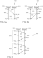
- Fig. 5a and 5b show examples 500, 550 for determining a synchronization accuracy using a residence time 510.
- the synchronization accuracy can be improved (e.g., the worst case error can be reduced) in that the master 310 additionally records a time stamp TM_IN at the earliest possible time after receipt of the request 320.
- the master integrates this time stamp TM_IM into its response 330 and thus enables the slave to determine the residence time 510, for example the master residence time (MRT), which the master required, for example, as processing time for the request 330.
- slave 300 can determine both the current time of the synchronized clock according to the linear interpolation function from the previous synchronization interval and the current time of the synchronized clock according to the linear interpolation function from the current synchronization interval.
- E tm_2(ts) - tm_1(ts).
- an expectation can be formed regarding the next synchronization time, which is expected to occur after the expiration of a cycle time T_SYNC.
- the presented method is universal and can be used anywhere trustworthy time synchronization is required.
- Trustworthy in this context can mean, for example, ASIL B compliant according to ISO 26262 and secure against malicious manipulation in terms of security.
- ASIL B compliant according to ISO 26262 For example, in a vehicle, it cannot necessarily be assumed that the communication channel between the control units can be implemented in a trustworthy manner. This applies, for example, to Ethernet networks. whose switches do not implement their functionality in an ASIL B-compliant manner. Implementing all network components in an ASIL B-compliant manner would entail considerable additional costs. Therefore, automotive-compatible solutions may not be developed, for example, according to IS026262 are certified. Furthermore, implementing the communication channel (cables, connectors, etc.) with trustworthy quality would be very complex and costly.
- FIG. 1 For example, a digital storage medium, for example a floppy disk, a DVD, a Blu-ray disc, a CD, a ROM, a PROM, an EPROM, an EEPROM or a FLASH memory, a hard disk, or another magnetic or optical memory on which electronically readable control signals are stored that can interact or interact with a programmable hardware component in such a way that the respective method is carried out.
- a digital storage medium for example a floppy disk, a DVD, a Blu-ray disc, a CD, a ROM, a PROM, an EPROM, an EEPROM or a FLASH memory, a hard disk, or another magnetic or optical memory on which electronically readable control signals are stored that can interact or interact with a programmable hardware component in such a way that the respective method is carried out.
- the digital storage medium can therefore be machine- or computer-readable.
- Some embodiments thus comprise a data carrier having electronically readable control signals capable of interacting with a programmable computer system or a programmable hardware component such that one of the methods described herein is performed.
- One embodiment is thus a data carrier (or a digital storage medium or a computer-readable medium) on which the program for performing one of the methods described herein is recorded.
- embodiments of the present invention can be implemented as a program, firmware, computer program, or computer program product with program code or data, wherein the program code or data is effective to perform one of the methods when the program runs on a processor or a programmable hardware component.
- the program code or data can also be stored, for example, on a machine-readable medium or data carrier.
- the program code or data can be present, among other things, as source code, machine code, or bytecode, as well as other intermediate code.
Landscapes
- Engineering & Computer Science (AREA)
- Computer Networks & Wireless Communication (AREA)
- Signal Processing (AREA)
- Environmental & Geological Engineering (AREA)
- Synchronisation In Digital Transmission Systems (AREA)
Claims (11)
- Procédé (100) permettant de déterminer une précision de synchronisation d'une synchronisation temporelle d'une première unité de communication (200, 300), le procédé (100) comprenant :l'envoi (110) d'une demande temporelle (320) par l'intermédiaire d'un canal de communication (210) à un moment d'envoi (TS1) correspondant de la première unité de communication (200, 300) à une seconde unité de communication (220, 310) ;la réception (120) d'une réponse temporelle (330), dans lequel la réponse temporelle (330) comprend une indication temporelle de synchronisation de la seconde unité de communication (220, 310), à un moment de réception (TS2) correspondant sur la première unité de communication (200, 300) ;la détermination (130) de la précision de synchronisation sur la base du moment d'envoi (TS1) et du moment de réception (TS2) ; etl'utilisation de l'indication temporelle de synchronisation de la seconde unité de communication (220, 310) pour une exécution d'une fonction de la première unité de communication (200, 300) en fonction de la précision de synchronisation,dans lequel un réseau sur fil est utilisé comme canal de communication (210), lequel réseau sur fil comprend au moins un composant avec un niveau de sécurité fonctionnelle inférieur à un niveau de sécurité fonctionnelle exigé par la fonction de la première unité de communication (200, 300), de sorte qu'il peut être défini si une précision de synchronisation prédéterminée requise est présente ou non lors d'une synchronisation temporelle par l'intermédiaire du réseau sur fil,caractérisé en ce que, sur la base d'une durée de cycle entre le moment d'envoi (TS1) et le moment de réception (TS2), une erreur de synchronisation définie pour la synchronisation temporelle est prise en compte en fonction de la fonction à exécuter.
- Procédé (100) permettant de déterminer une précision de synchronisation d'une synchronisation temporelle d'une première unité de communication (200, 300), le procédé (100) comprenant :l'envoi (110) d'une demande temporelle (320) par l'intermédiaire d'un canal de communication (210) à un moment d'envoi (TS1) correspondant de la première unité de communication (200, 300) à une seconde unité de communication (220, 310) ;la réception (120) d'une réponse temporelle (330), dans lequel la réponse temporelle (330) comprend une indication temporelle de synchronisation de la seconde unité de communication (220, 310), à un moment de réception (TS2) correspondant sur la première unité de communication (200, 300) ;la détermination (130) de la précision de synchronisation sur la base du moment d'envoi (TS1) et du moment de réception (TS2) ; etl'utilisation de l'indication temporelle de synchronisation de la seconde unité de communication (220, 310) pour une exécution d'une fonction de la première unité de communication (200, 300) en fonction de la précision de synchronisation,dans lequel un réseau sur fil est utilisé comme canal de communication (210), lequel réseau sur fil comprend au moins un composant avec un niveau de sécurité fonctionnelle inférieur à un niveau de sécurité fonctionnelle exigé par la fonction de la première unité de communication (200, 300), de sorte qu'il peut être défini si une précision de synchronisation prédéterminée requise est présente ou non lors d'une synchronisation temporelle par l'intermédiaire du réseau sur fil,caractérisé en ce qu'une nouvelle demande temporelle (320) est envoyée si la précision de synchronisation est inférieure à une précision de synchronisation requise pour la fonction à exécuter.
- Procédé (100) selon la revendication 1 ou 2, dans lequel une durée (510) entre la réception de la demande temporelle et l'envoi de la réponse temporelle (330) à la seconde unité de communication (220, 310) est en outre prise en compte pour la détermination de la précision de synchronisation, laquelle durée est incluse comme temps d'attente dans la réponse temporelle, et/ou un moment de réception de la réponse temporelle et un moment d'envoi de la réponse temporelle sont pris en compte, lesquels sont inclus dans la réponse temporelle.
- Procédé (100) selon l'une des revendications précédentes, dans lequel une inexactitude de précision d'une horloge de la première unité de communication (200, 300) par rapport à une horloge de la seconde unité de communication (220, 310) est compensée en utilisant un taux de déviation, dans lequel le taux de déviation est défini sur la base d'au moins un autre envoi d'une demande temporelle (320) et d'une autre réception correspondante d'une réponse temporelle (330).
- Procédé (100) selon l'une des revendications précédentes, dans lequel une pluralité de demandes temporelles (320) sont envoyées par la première unité de communication (200, 300) par l'intermédiaire du canal de communication (210) à une pluralité correspondante d'unités de communication (220, 310) configurées de manière correspondante au moins en ce qui concerne un envoi de la réponse temporelle (330) de la seconde unité de communication.
- Procédé (100) selon l'une des revendications précédentes, dans lequel, en cas d'écart entre l'indication temporelle de synchronisation de la seconde unité de communication (220, 310) et une indication temporelle de la première unité de communication (200, 300), une adaptation de l'indication temporelle de la première unité de communication (200, 300) à l'indication temporelle de synchronisation est effectuée progressivement.
- Procédé (100) selon l'une des revendications précédentes, dans lequel des caractéristiques d'identification et/ou des totaux de contrôle et/ou des signatures respectifs sont joints à la demande temporelle (320) et à la réponse temporelle (330), grâce auxquels une réponse temporelle (330) est affectée de manière univoque à une demande temporelle (320) correspondante.
- Procédé (100) selon l'une des revendications précédentes, dans lequel une sécurité de manipulation de la réponse temporelle (330) et/ou de la demande temporelle est augmentée en utilisant au moins un procédé cryptographique, dans lequel le message respectif est signé avec un procédé cryptographique.
- Programme informatique permettant l'exécution d'un procédé (100) selon l'une des revendications 1 à 8, lorsque le programme informatique est lancé sur un ordinateur, un processeur ou un composant matériel programmable.
- Unité de communication (200, 220, 300, 310) destinée à se connecter à un canal de communication (210), dans laquelle l'unité de communication (200, 220, 300, 310) comprend au moins une horloge et est en outre configurée pour exécuter un procédé selon l'une des revendications 1 à 8.
- Véhicule automobile comportant au moins un canal de communication (210), dans lequel le véhicule automobile comprend au moins une unité de communication (200) selon la revendication 10.
Applications Claiming Priority (2)
| Application Number | Priority Date | Filing Date | Title |
|---|---|---|---|
| DE102018207684.7A DE102018207684A1 (de) | 2018-05-17 | 2018-05-17 | Verfahren zum Bestimmen einer Synchronisationsgenauigkeit, Computerprogramm, Kommunikationseinheit und Kraftfahrzeug |
| PCT/EP2019/059888 WO2019219316A1 (fr) | 2018-05-17 | 2019-04-17 | Procédé de détermination d'une précision de synchronisation, programme d'ordinateur, unité de communication et véhicule automobile |
Publications (2)
| Publication Number | Publication Date |
|---|---|
| EP3794751A1 EP3794751A1 (fr) | 2021-03-24 |
| EP3794751B1 true EP3794751B1 (fr) | 2025-04-09 |
Family
ID=66286323
Family Applications (1)
| Application Number | Title | Priority Date | Filing Date |
|---|---|---|---|
| EP19719463.2A Active EP3794751B1 (fr) | 2018-05-17 | 2019-04-17 | Procede pour determiner la precision de synchronisation, programme informatique, unite de communication et vehicule automobil |
Country Status (5)
| Country | Link |
|---|---|
| US (1) | US11522778B2 (fr) |
| EP (1) | EP3794751B1 (fr) |
| CN (1) | CN112106314B (fr) |
| DE (1) | DE102018207684A1 (fr) |
| WO (1) | WO2019219316A1 (fr) |
Families Citing this family (10)
| Publication number | Priority date | Publication date | Assignee | Title |
|---|---|---|---|---|
| DE102018207684A1 (de) | 2018-05-17 | 2019-11-21 | Volkswagen Aktiengesellschaft | Verfahren zum Bestimmen einer Synchronisationsgenauigkeit, Computerprogramm, Kommunikationseinheit und Kraftfahrzeug |
| DE102019220495A1 (de) | 2019-12-20 | 2021-06-24 | Continental Automotive Gmbh | Verfahren zur Prüfung der Gültigkeit von Sensordaten eines Ethernet-Bordnetzes |
| WO2021164882A1 (fr) * | 2020-02-21 | 2021-08-26 | Bayerische Motoren Werke Aktiengesellschaft | Procédé et système d'exécution de synchronisation temporelle |
| JP2021142925A (ja) * | 2020-03-13 | 2021-09-24 | フォルシアクラリオン・エレクトロニクス株式会社 | 遠隔操作判定装置及び遠隔操作判定システム |
| US11321163B2 (en) * | 2020-03-26 | 2022-05-03 | Wipro Limited | Device and method for monitoring functional safety in integrated circuits (ICS) |
| DE102020215247A1 (de) * | 2020-12-02 | 2022-06-02 | Continental Automotive Gmbh | Verfahren zur Ermittlung der Steuergerätetemperatur durch ein Zeitsynchronisationsprotokoll |
| EP4040824A1 (fr) * | 2021-02-05 | 2022-08-10 | Volvo Truck Corporation | Procédé permettant d'anonymiser une source de transmissions numériques |
| CN115801164A (zh) | 2021-09-10 | 2023-03-14 | B和R工业自动化有限公司 | 网络中的时间同步 |
| DE102022210800A1 (de) | 2022-10-13 | 2024-04-18 | Robert Bosch Gesellschaft mit beschränkter Haftung | Verfahren zum drahtlosen zeitlichen Synchronisieren einer ersten elektrischen Einheit mit einer zweiten elektrischen Einheit |
| CN115967647B (zh) * | 2022-12-30 | 2025-07-08 | 北京信而泰科技股份有限公司 | 一种测试网络同步的测试设备、方法、装置和存储介质 |
Citations (2)
| Publication number | Priority date | Publication date | Assignee | Title |
|---|---|---|---|---|
| DE102014200558A1 (de) * | 2014-01-15 | 2015-07-16 | Bayerische Motoren Werke Aktiengesellschaft | Gesicherter Netzwerk-Zugangsschutz über authentifizierte Zeitmessung |
| US20150236940A1 (en) * | 2012-09-18 | 2015-08-20 | Continental Automotive Gmbh | Method for monitoring an Ethernet-based communication network in a motor vehicle |
Family Cites Families (16)
| Publication number | Priority date | Publication date | Assignee | Title |
|---|---|---|---|---|
| US7194556B2 (en) * | 2001-03-30 | 2007-03-20 | Intel Corporation | Method and apparatus for high accuracy distributed time synchronization using processor tick counters |
| KR100504835B1 (ko) * | 2003-05-15 | 2005-07-29 | 엘지전자 주식회사 | 이동 통신 단말기의 지역시간 보정 방법 |
| US6845235B1 (en) * | 2003-07-18 | 2005-01-18 | Motorola, Inc. | Method and apparatus in a wireless communication system for expediting a request for uplink resources |
| DE102008026574A1 (de) | 2008-05-30 | 2009-12-10 | Siemens Aktiengesellschaft | Steuerungssystem, Steuerrechner sowie Verfahren zum Betreiben eine Steuerungssystems |
| CN101867469B (zh) * | 2010-06-10 | 2014-09-24 | 北京东土科技股份有限公司 | 一种精密同步时钟的实现方法 |
| JP5358813B2 (ja) * | 2011-03-30 | 2013-12-04 | 株式会社日立製作所 | ネットワークノード、時刻同期方法及びネットワークシステム |
| US9112630B1 (en) * | 2012-02-09 | 2015-08-18 | Marvell Israel (M.I.S.L) Ltd. | Clock synchronization in the presence of security threats |
| AT515454A3 (de) | 2013-03-14 | 2018-07-15 | Fts Computertechnik Gmbh | Verfahren zur Behandlung von Fehlern in einem zentralen Steuergerät sowie Steuergerät |
| CN105262555B (zh) * | 2014-07-16 | 2021-05-28 | 中兴通讯股份有限公司 | 一种时间同步方法、可编程逻辑器件、单板及网元 |
| DE102014214274A1 (de) | 2014-07-22 | 2016-01-28 | Siemens Aktiengesellschaft | Verfahren und Knoten zum Senden von Nachrichten sowie Computerprogrammprodukt |
| DE102014214823A1 (de) | 2014-07-29 | 2016-02-04 | Bayerische Motoren Werke Aktiengesellschaft | Bestimmung einer Verzögerung |
| DE102014217993A1 (de) | 2014-09-09 | 2016-03-10 | Siemens Aktiengesellschaft | Sender, Empfänger, Zwischenknoten und Verfahren zum Synchronisieren von mindestens einer Uhr mindestens eines Empfängers mit einer Uhr eines Senders |
| DE102014222216A1 (de) | 2014-10-30 | 2016-05-04 | Robert Bosch Gmbh | Verfahren und Vorrichtung zur Absicherung einer Kommunikation |
| WO2016095099A1 (fr) * | 2014-12-16 | 2016-06-23 | 华为技术有限公司 | Procédé et appareil de synchronisation temporelle |
| US9954669B2 (en) | 2016-01-06 | 2018-04-24 | Alcatel-Lucent Usa Inc. | Method and apparatus for over-the-air anchor-anchor synchronization |
| DE102018207684A1 (de) | 2018-05-17 | 2019-11-21 | Volkswagen Aktiengesellschaft | Verfahren zum Bestimmen einer Synchronisationsgenauigkeit, Computerprogramm, Kommunikationseinheit und Kraftfahrzeug |
-
2018
- 2018-05-17 DE DE102018207684.7A patent/DE102018207684A1/de active Pending
-
2019
- 2019-04-17 WO PCT/EP2019/059888 patent/WO2019219316A1/fr not_active Ceased
- 2019-04-17 US US17/055,093 patent/US11522778B2/en active Active
- 2019-04-17 EP EP19719463.2A patent/EP3794751B1/fr active Active
- 2019-04-17 CN CN201980033153.7A patent/CN112106314B/zh active Active
Patent Citations (2)
| Publication number | Priority date | Publication date | Assignee | Title |
|---|---|---|---|---|
| US20150236940A1 (en) * | 2012-09-18 | 2015-08-20 | Continental Automotive Gmbh | Method for monitoring an Ethernet-based communication network in a motor vehicle |
| DE102014200558A1 (de) * | 2014-01-15 | 2015-07-16 | Bayerische Motoren Werke Aktiengesellschaft | Gesicherter Netzwerk-Zugangsschutz über authentifizierte Zeitmessung |
Also Published As
| Publication number | Publication date |
|---|---|
| CN112106314A (zh) | 2020-12-18 |
| CN112106314B (zh) | 2024-04-09 |
| WO2019219316A1 (fr) | 2019-11-21 |
| US11522778B2 (en) | 2022-12-06 |
| DE102018207684A1 (de) | 2019-11-21 |
| US20210218656A1 (en) | 2021-07-15 |
| EP3794751A1 (fr) | 2021-03-24 |
Similar Documents
| Publication | Publication Date | Title |
|---|---|---|
| EP3794751B1 (fr) | Procede pour determiner la precision de synchronisation, programme informatique, unite de communication et vehicule automobil | |
| EP4078921B1 (fr) | Procédé de sécurisation de la synchronisation temporelle d'un réseau embarqué ethernet | |
| DE102017219209B4 (de) | Verfahren zum Erkennen eines fehlerhaften Zeitstempels einer Ethernet-Nachricht und Steuereinheit für ein Kraftfahrzeug | |
| EP2569896B1 (fr) | Procédé et dispositif d'authentification de messages multidiffusés | |
| EP4078863B1 (fr) | Procede de verification de la validité des données de capteurs dans un reseau ethertnet d'un vehicule | |
| EP4073963B1 (fr) | Procédé de synchronisation du temps entre des dsipositifs de reseau connectés par un reseau de commmunication | |
| EP4055794B1 (fr) | Procédé de sécuriser la synchronisation du temps d'un reseau contre modifications non autorisées | |
| DE102019220498B4 (de) | Verfahren zur Absicherung der Zeitsynchronisation in einem Server ECU | |
| EP4256730B1 (fr) | Procede de determination de la temperature d'une ecu par un procotol de synchronisation du temps | |
| DE102012204586A1 (de) | Gateway, Knoten und Verfahren für ein Fahrzeug | |
| WO2014044655A1 (fr) | Procédé de surveillance d'un réseau de communication basé sur ethernet dans un véhicule automobile | |
| DE102013224697A1 (de) | Verfahren zum Etablieren einer gemeinsamen Zeitbasis für Netzwerkteilnehmer in einem Netzwerk eines Kraftfahrzeugs | |
| EP2036263A1 (fr) | Procédé et équipement de l'établissement d'un système de communication à base contrôleurs de communication can avec débit de données accru | |
| EP4009683B1 (fr) | Procédé de synchronisation des horloges d'au moins deux appareils | |
| DE102012210327A1 (de) | Verfahren zum Übertragen von Nachrichten in einem Kommunikationssystem, insbesondere eines Fahrzeugs | |
| EP3820105B1 (fr) | Procédé et système de synchronisation temporelle sécurisée | |
| DE102014001270A1 (de) | Verfahren und System zur Berechnung von Codewörtern für geschützte Datenübertragungen | |
| DE102019217037A1 (de) | Verfahren zur Absicherung der Zeitsynchronisation in einem Netzwerk | |
| EP3905731B1 (fr) | Procédé de synchronisation du compteur par trame et agencement | |
| DE102014217993A1 (de) | Sender, Empfänger, Zwischenknoten und Verfahren zum Synchronisieren von mindestens einer Uhr mindestens eines Empfängers mit einer Uhr eines Senders | |
| DE102022213581A1 (de) | Verfahren zum überwachen einer kommunikationsverbindung zweier direkt miteinander verbundener netzwerkknoten |
Legal Events
| Date | Code | Title | Description |
|---|---|---|---|
| STAA | Information on the status of an ep patent application or granted ep patent |
Free format text: STATUS: UNKNOWN |
|
| STAA | Information on the status of an ep patent application or granted ep patent |
Free format text: STATUS: THE INTERNATIONAL PUBLICATION HAS BEEN MADE |
|
| PUAI | Public reference made under article 153(3) epc to a published international application that has entered the european phase |
Free format text: ORIGINAL CODE: 0009012 |
|
| STAA | Information on the status of an ep patent application or granted ep patent |
Free format text: STATUS: REQUEST FOR EXAMINATION WAS MADE |
|
| 17P | Request for examination filed |
Effective date: 20201217 |
|
| AK | Designated contracting states |
Kind code of ref document: A1 Designated state(s): AL AT BE BG CH CY CZ DE DK EE ES FI FR GB GR HR HU IE IS IT LI LT LU LV MC MK MT NL NO PL PT RO RS SE SI SK SM TR |
|
| AX | Request for extension of the european patent |
Extension state: BA ME |
|
| DAV | Request for validation of the european patent (deleted) | ||
| DAX | Request for extension of the european patent (deleted) | ||
| STAA | Information on the status of an ep patent application or granted ep patent |
Free format text: STATUS: EXAMINATION IS IN PROGRESS |
|
| 17Q | First examination report despatched |
Effective date: 20240314 |
|
| GRAP | Despatch of communication of intention to grant a patent |
Free format text: ORIGINAL CODE: EPIDOSNIGR1 |
|
| STAA | Information on the status of an ep patent application or granted ep patent |
Free format text: STATUS: GRANT OF PATENT IS INTENDED |
|
| RIC1 | Information provided on ipc code assigned before grant |
Ipc: H04L 69/28 20220101ALN20241016BHEP Ipc: H04L 12/40 20060101ALN20241016BHEP Ipc: H04L 43/08 20220101ALI20241016BHEP Ipc: H04J 3/14 20060101ALI20241016BHEP Ipc: H04J 3/06 20060101AFI20241016BHEP |
|
| INTG | Intention to grant announced |
Effective date: 20241030 |
|
| GRAS | Grant fee paid |
Free format text: ORIGINAL CODE: EPIDOSNIGR3 |
|
| GRAA | (expected) grant |
Free format text: ORIGINAL CODE: 0009210 |
|
| STAA | Information on the status of an ep patent application or granted ep patent |
Free format text: STATUS: THE PATENT HAS BEEN GRANTED |
|
| AK | Designated contracting states |
Kind code of ref document: B1 Designated state(s): AL AT BE BG CH CY CZ DE DK EE ES FI FR GB GR HR HU IE IS IT LI LT LU LV MC MK MT NL NO PL PT RO RS SE SI SK SM TR |
|
| REG | Reference to a national code |
Ref country code: GB Ref legal event code: FG4D Free format text: NOT ENGLISH |
|
| REG | Reference to a national code |
Ref country code: CH Ref legal event code: EP |
|
| REG | Reference to a national code |
Ref country code: DE Ref legal event code: R096 Ref document number: 502019013178 Country of ref document: DE |
|
| REG | Reference to a national code |
Ref country code: IE Ref legal event code: FG4D Free format text: LANGUAGE OF EP DOCUMENT: GERMAN |
|
| PGFP | Annual fee paid to national office [announced via postgrant information from national office to epo] |
Ref country code: DE Payment date: 20250430 Year of fee payment: 7 |
|
| PGFP | Annual fee paid to national office [announced via postgrant information from national office to epo] |
Ref country code: GB Payment date: 20250422 Year of fee payment: 7 |
|
| PGFP | Annual fee paid to national office [announced via postgrant information from national office to epo] |
Ref country code: FR Payment date: 20250424 Year of fee payment: 7 |
|
| REG | Reference to a national code |
Ref country code: NL Ref legal event code: MP Effective date: 20250409 |
|
| PG25 | Lapsed in a contracting state [announced via postgrant information from national office to epo] |
Ref country code: NL Free format text: LAPSE BECAUSE OF FAILURE TO SUBMIT A TRANSLATION OF THE DESCRIPTION OR TO PAY THE FEE WITHIN THE PRESCRIBED TIME-LIMIT Effective date: 20250409 |
|
| PG25 | Lapsed in a contracting state [announced via postgrant information from national office to epo] |
Ref country code: PT Free format text: LAPSE BECAUSE OF FAILURE TO SUBMIT A TRANSLATION OF THE DESCRIPTION OR TO PAY THE FEE WITHIN THE PRESCRIBED TIME-LIMIT Effective date: 20250811 Ref country code: FI Free format text: LAPSE BECAUSE OF FAILURE TO SUBMIT A TRANSLATION OF THE DESCRIPTION OR TO PAY THE FEE WITHIN THE PRESCRIBED TIME-LIMIT Effective date: 20250409 Ref country code: ES Free format text: LAPSE BECAUSE OF FAILURE TO SUBMIT A TRANSLATION OF THE DESCRIPTION OR TO PAY THE FEE WITHIN THE PRESCRIBED TIME-LIMIT Effective date: 20250409 |
|
| REG | Reference to a national code |
Ref country code: LT Ref legal event code: MG9D |
|
| PG25 | Lapsed in a contracting state [announced via postgrant information from national office to epo] |
Ref country code: NO Free format text: LAPSE BECAUSE OF FAILURE TO SUBMIT A TRANSLATION OF THE DESCRIPTION OR TO PAY THE FEE WITHIN THE PRESCRIBED TIME-LIMIT Effective date: 20250709 Ref country code: GR Free format text: LAPSE BECAUSE OF FAILURE TO SUBMIT A TRANSLATION OF THE DESCRIPTION OR TO PAY THE FEE WITHIN THE PRESCRIBED TIME-LIMIT Effective date: 20250710 |
|
| PG25 | Lapsed in a contracting state [announced via postgrant information from national office to epo] |
Ref country code: PL Free format text: LAPSE BECAUSE OF FAILURE TO SUBMIT A TRANSLATION OF THE DESCRIPTION OR TO PAY THE FEE WITHIN THE PRESCRIBED TIME-LIMIT Effective date: 20250409 |
|
| PG25 | Lapsed in a contracting state [announced via postgrant information from national office to epo] |
Ref country code: BG Free format text: LAPSE BECAUSE OF FAILURE TO SUBMIT A TRANSLATION OF THE DESCRIPTION OR TO PAY THE FEE WITHIN THE PRESCRIBED TIME-LIMIT Effective date: 20250409 |
|
| PG25 | Lapsed in a contracting state [announced via postgrant information from national office to epo] |
Ref country code: HR Free format text: LAPSE BECAUSE OF FAILURE TO SUBMIT A TRANSLATION OF THE DESCRIPTION OR TO PAY THE FEE WITHIN THE PRESCRIBED TIME-LIMIT Effective date: 20250409 |
|
| PG25 | Lapsed in a contracting state [announced via postgrant information from national office to epo] |
Ref country code: RS Free format text: LAPSE BECAUSE OF FAILURE TO SUBMIT A TRANSLATION OF THE DESCRIPTION OR TO PAY THE FEE WITHIN THE PRESCRIBED TIME-LIMIT Effective date: 20250709 |
|
| PG25 | Lapsed in a contracting state [announced via postgrant information from national office to epo] |
Ref country code: IS Free format text: LAPSE BECAUSE OF FAILURE TO SUBMIT A TRANSLATION OF THE DESCRIPTION OR TO PAY THE FEE WITHIN THE PRESCRIBED TIME-LIMIT Effective date: 20250809 |
|
| PG25 | Lapsed in a contracting state [announced via postgrant information from national office to epo] |
Ref country code: LV Free format text: LAPSE BECAUSE OF FAILURE TO SUBMIT A TRANSLATION OF THE DESCRIPTION OR TO PAY THE FEE WITHIN THE PRESCRIBED TIME-LIMIT Effective date: 20250409 |
|
| REG | Reference to a national code |
Ref country code: CH Ref legal event code: H13 Free format text: ST27 STATUS EVENT CODE: U-0-0-H10-H13 (AS PROVIDED BY THE NATIONAL OFFICE) Effective date: 20251125 |
|
| PG25 | Lapsed in a contracting state [announced via postgrant information from national office to epo] |
Ref country code: LU Free format text: LAPSE BECAUSE OF NON-PAYMENT OF DUE FEES Effective date: 20250417 |
|
| REG | Reference to a national code |
Ref country code: BE Ref legal event code: MM Effective date: 20250430 |
|
| REG | Reference to a national code |
Ref country code: DE Ref legal event code: R097 Ref document number: 502019013178 Country of ref document: DE |
|
| PG25 | Lapsed in a contracting state [announced via postgrant information from national office to epo] |
Ref country code: DK Free format text: LAPSE BECAUSE OF FAILURE TO SUBMIT A TRANSLATION OF THE DESCRIPTION OR TO PAY THE FEE WITHIN THE PRESCRIBED TIME-LIMIT Effective date: 20250409 Ref country code: SM Free format text: LAPSE BECAUSE OF FAILURE TO SUBMIT A TRANSLATION OF THE DESCRIPTION OR TO PAY THE FEE WITHIN THE PRESCRIBED TIME-LIMIT Effective date: 20250409 |
|
| PG25 | Lapsed in a contracting state [announced via postgrant information from national office to epo] |
Ref country code: BE Free format text: LAPSE BECAUSE OF NON-PAYMENT OF DUE FEES Effective date: 20250430 |
|
| PG25 | Lapsed in a contracting state [announced via postgrant information from national office to epo] |
Ref country code: CH Free format text: LAPSE BECAUSE OF NON-PAYMENT OF DUE FEES Effective date: 20250430 |
|
| PG25 | Lapsed in a contracting state [announced via postgrant information from national office to epo] |
Ref country code: CZ Free format text: LAPSE BECAUSE OF FAILURE TO SUBMIT A TRANSLATION OF THE DESCRIPTION OR TO PAY THE FEE WITHIN THE PRESCRIBED TIME-LIMIT Effective date: 20250409 |
|
| PG25 | Lapsed in a contracting state [announced via postgrant information from national office to epo] |
Ref country code: EE Free format text: LAPSE BECAUSE OF FAILURE TO SUBMIT A TRANSLATION OF THE DESCRIPTION OR TO PAY THE FEE WITHIN THE PRESCRIBED TIME-LIMIT Effective date: 20250409 |
|
| PG25 | Lapsed in a contracting state [announced via postgrant information from national office to epo] |
Ref country code: RO Free format text: LAPSE BECAUSE OF FAILURE TO SUBMIT A TRANSLATION OF THE DESCRIPTION OR TO PAY THE FEE WITHIN THE PRESCRIBED TIME-LIMIT Effective date: 20250409 Ref country code: SK Free format text: LAPSE BECAUSE OF FAILURE TO SUBMIT A TRANSLATION OF THE DESCRIPTION OR TO PAY THE FEE WITHIN THE PRESCRIBED TIME-LIMIT Effective date: 20250409 |
|
| PG25 | Lapsed in a contracting state [announced via postgrant information from national office to epo] |
Ref country code: IT Free format text: LAPSE BECAUSE OF FAILURE TO SUBMIT A TRANSLATION OF THE DESCRIPTION OR TO PAY THE FEE WITHIN THE PRESCRIBED TIME-LIMIT Effective date: 20250409 |
|
| PG25 | Lapsed in a contracting state [announced via postgrant information from national office to epo] |
Ref country code: MC Free format text: LAPSE BECAUSE OF FAILURE TO SUBMIT A TRANSLATION OF THE DESCRIPTION OR TO PAY THE FEE WITHIN THE PRESCRIBED TIME-LIMIT Effective date: 20250409 |
|
| PLBE | No opposition filed within time limit |
Free format text: ORIGINAL CODE: 0009261 |
|
| STAA | Information on the status of an ep patent application or granted ep patent |
Free format text: STATUS: NO OPPOSITION FILED WITHIN TIME LIMIT |
|
| REG | Reference to a national code |
Ref country code: CH Ref legal event code: L10 Free format text: ST27 STATUS EVENT CODE: U-0-0-L10-L00 (AS PROVIDED BY THE NATIONAL OFFICE) Effective date: 20260218 |
|
| 26N | No opposition filed |
Effective date: 20260112 |
|
| PG25 | Lapsed in a contracting state [announced via postgrant information from national office to epo] |
Ref country code: IE Free format text: LAPSE BECAUSE OF NON-PAYMENT OF DUE FEES Effective date: 20250417 |