EP3794861B1 - Simulation de performance d'un système d'antennes mimo distribuées - Google Patents
Simulation de performance d'un système d'antennes mimo distribuées Download PDFInfo
- Publication number
- EP3794861B1 EP3794861B1 EP19728519.0A EP19728519A EP3794861B1 EP 3794861 B1 EP3794861 B1 EP 3794861B1 EP 19728519 A EP19728519 A EP 19728519A EP 3794861 B1 EP3794861 B1 EP 3794861B1
- Authority
- EP
- European Patent Office
- Prior art keywords
- rank
- cell
- antenna deployment
- antenna
- determining
- Prior art date
- Legal status (The legal status is an assumption and is not a legal conclusion. Google has not performed a legal analysis and makes no representation as to the accuracy of the status listed.)
- Active
Links
Images




Classifications
-
- H—ELECTRICITY
- H04—ELECTRIC COMMUNICATION TECHNIQUE
- H04W—WIRELESS COMMUNICATION NETWORKS
- H04W16/00—Network planning, e.g. coverage or traffic planning tools; Network deployment, e.g. resource partitioning or cells structures
- H04W16/18—Network planning tools
- H04W16/20—Network planning tools for indoor coverage or short range network deployment
-
- H—ELECTRICITY
- H04—ELECTRIC COMMUNICATION TECHNIQUE
- H04W—WIRELESS COMMUNICATION NETWORKS
- H04W16/00—Network planning, e.g. coverage or traffic planning tools; Network deployment, e.g. resource partitioning or cells structures
- H04W16/18—Network planning tools
-
- H—ELECTRICITY
- H04—ELECTRIC COMMUNICATION TECHNIQUE
- H04B—TRANSMISSION
- H04B17/00—Monitoring; Testing
- H04B17/30—Monitoring; Testing of propagation channels
- H04B17/309—Measuring or estimating channel quality parameters
- H04B17/336—Signal-to-interference ratio [SIR] or carrier-to-interference ratio [CIR]
-
- H—ELECTRICITY
- H04—ELECTRIC COMMUNICATION TECHNIQUE
- H04B—TRANSMISSION
- H04B7/00—Radio transmission systems, i.e. using radiation field
- H04B7/02—Diversity systems; Multi-antenna system, i.e. transmission or reception using multiple antennas
- H04B7/04—Diversity systems; Multi-antenna system, i.e. transmission or reception using multiple antennas using two or more spaced independent antennas
- H04B7/0413—MIMO systems
Definitions
- the disclosure relates to designing wireless communications, and in particular, to designing Multiple-Input and Multiple-Output (MIMO) networks.
- MIMO Multiple-Input and Multiple-Output
- Planning products can be used to design network deployments. Some enable the automation of some of the planning process, significantly reducing planning times. Some planning products enable users to import a floor plan and use it to create a plan for the locations of network products and associated cabling. Users can modify several floor attributes including wall materials and structures to produce more accurate planning results. Users can also modify node locations to suit their own situation. Output from the tool sometimes includes a coverage report, a Bill of Materials to help in ordering, and a solution report listing the required hardware and cabling on each floor of the building.
- MIMO Multiple-Input and Multiple-Output
- Document US 2013/0183961 A1 discloses a method and system for communication network design.
- the method includes generating, by a computer processor, a plurality of receiver points and generating a target received signal strength for each receiver point of the plurality of receiver points.
- the method further includes determining a predicted number of antennas based on a size of the communications network and a coverage area of an antenna, and determining a location for each antenna of the predicted number of antennas.
- the method still further includes generating an estimated received signal strength for each receiver point of the plurality of receiver points, based upon the predicted number of antennas and upon the location of each antenna of the predicted number of antennas.
- the method also includes comparing the estimated received signal strength for each receiver point with the target received signal strength for the receiver point and generating a revised predicted number of antennas based upon at least one of the comparisons of target received signal strength and estimated received signal strength.
- Document CN 102 098 689 A discloses an automatic antenna distribution method and an automatic antenna distribution system for an indoor distributed wireless network.
- the method comprises the following steps of: 1, initializing the antenna distribution density and antenna distribution positions of the indoor distributed wireless network to be distributed; 2, simulating current distribution by using a preset propagation model; 3, judging whether a coverage simulation result meets the requirements of a preset coverage objective or not, performing a step 4 if the coverage simulation result does not meet the requirements of the preset coverage objective, and finishing the arrangement if the coverage simulation result meets the requirements of the preset coverage objective; 4, calculating a wireless signal field intensity attenuation gradient of the antenna distribution positions in divided directional lines according to the simulation result of the current distribution of antennae, and regulating the antenna distribution positions according to the wireless signal field intensity attenuation gradient; and 5, searching for coverage holes and overlapped coverage areas of the indoor distributed wireless network according to the simulation result, regulating the antenna distribution intensity according to the coverage holes and the overlapped coverage areas, and performing the step 2.
- Document US 7 085 697 B1 discloses a computerized model providing a display of a physical environment in which a communications network is or will be installed.
- the communications network is comprised of several components, each of which are selected by the design engineer and which are represented in the display. Errors in the selection of certain selected components for the communications network are identified by their attributes or frequency characteristics as well as by their interconnection compatibility for a particular design. The effects of changes in frequency on component performance are modeled and the results are displayed to the design engineer. A bill of materials is automatically checked for faults, generated for the design system and provided to the design engineer. For ease of design, the design engineer can cluster several different preferred components into component kits, and then select these component kits for use In the design or deployment process.
- a method and a computation node for determining a performance metric for an antenna deployment are provided according to the independent claims. Preferred embodiments are recited in the dependent claims.
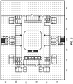
- a floorplan is used such as is shown in Figure 1 . This may include outside walls, inside walls and various other structures. Additionally, the materials of these structures may be defined and/or the radio propagation characteristics may be known or derived.
- Figure 2 illustrates another example floorplan that has been segmented into discrete locations.
- many individual points inside the floorplan are assigned x, y coordinates. If an antenna is placed in this floorplan, various radio characteristics can be calculated for these x, y coordinates.
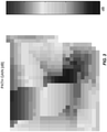
- Figure 3 shows an example where path gain is computed for the points in the floorplan.
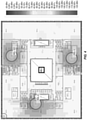
- Figure 4 shows a more detailed visualization of the floorplan of Figure 1 .
- MIMO Multiple-Input and Multiple-Input and Multiple-Output
- a method includes obtaining the antenna deployment including antennas and corresponding locations for the antennas, a cell assignment for the antennas such that each antenna is assigned to one cell out of one or more cells, and a resource assignment for the antennas such that each antenna is assigned to one radio resource out of one or more radio resources. Based on the antenna deployment, the cell assignment, and the resource assignment, the method determines at least one performance metric of the antenna deployment. This may provide a lightweight and efficient method to design a distributed antenna deployment. The resulting network may be optimized in terms the total area where a high rank is achieved.
- Figure 5 illustrates a method for determining a performance metric for an antenna deployment.
- an antenna deployment including antennas and corresponding locations for the antennas, a cell assignment for the antennas such that each antenna is assigned to one cell out of one or more cells, and a resource assignment for the antennas such that each antenna is assigned to one radio resource out of one or more radio resources are obtained (step 500).
- the method determines at least one performance metric of the antenna deployment (step 502).
- the method takes an antenna deployment as an input.
- This input can be user-defined or automatically generated by an optimization algorithm.
- the x and y coordinates of the antennas and the path loss of the deployment area are used to compute the following outputs: assignment of antennas to radio resources (also referred to as data streams) and cells.
- radio resources also referred to as data streams
- each cell transmits N data streams.
- Antennas can only transmit a single, unique data stream, as such data streams must be assigned to antennas optimally such that users see the maximum benefit of a MIMO network.
- MIMO network performance is maximized when a good signal is received from each unique data stream.
- the Ericsson Indoor Planner (EIP) tool is used to generate an antenna deployment.
- the solution is inserted after the deployment step and after radio resources are assigned to antennas.
- Figure 6 realizes the integration of this solution with an existing deployment tool.
- an existing antenna deployment such as a Distributed Antenna System (DAS) head deployment
- DAS Distributed Antenna System
- each head is assigned first to a cell and then to a radio; via the processes depicted in Figure 6 .
- antennas are assigned to cells (step 602).
- radio resources are assigned to the antennas (step 604).
- the performance can then be calculated (step 606) and the method can return to some remaining system (608). Additional details regarding the calculation of performance are provided in Figures 7 through 10 .
- Figure 7 illustrates an example implementation of step 606. In some embodiments, all three of these steps are performed. In other embodiments, only a subset of these steps is performed.
- the Rank of the antenna deployment is calculated (step 700).
- a cumulative signal is calculated (step 702).
- the bitrate for the antenna deployment can be calculated (step 704).
- Figures 8 , 9 , and 10 outline exemplary methods used to calculate Rank, cumulative signal, and bitrate. In the following figures, once a radio resource has been assigned to an antenna, that antenna emits a data stream unique to that radio resource.
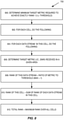
- Figure 8 illustrates an exemplary implementation of step 700.
- the first step is to choose an appropriate metric (or combination) that has a strong relationship to the Rank.
- find the threshold required to achieve at least a Rank of 1.0 step 800.
- empirical data was collected, and a threshold was extracted.
- the following steps are then taken to calculate Rank (using signal power as the metric):
- the total Rank for this antenna deployment is the maximum rank over all of the cells (step 812).
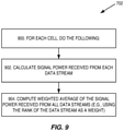
- Figure 9 illustrates an exemplary implementation of step 702.
- the per-data stream Rank can be used to find an equivalent cumulative signal. To do this, for each cell (step 900), the signal received from antennas emitting the same data stream is summed (step 902). The summed signal of each data stream is then multiplied by a weight derived from its Rank and summed with the weighted signals of the other data streams in this cell (step 904). Alternatively, the resulting cell signal can be found by summing the signals of all data streams of the same cell, instead of using the weighted average approach.
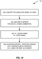
- Figure 10 illustrates an exemplary implementation of step 704.
- the cumulative signal In order to calculate the bitrate, the cumulative signal must be converted to a SINR (step 1000) and this SINR, in turn, is converted to a bitrate. If the maximum achievable Rank is N, then a unique SINR to bitrate conversion is done for each of the following 1x1, 2x2, ..., NxN antenna configurations (step 1002).
- the achievable bitrate is calculated as the weighted average of the MxM and NxN bitrates (where M and N are the closest integers to the Rank achieved in this area) (step 1006).
- the weight is determined by how close the achieved Rank is to M and N.
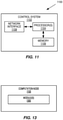
- FIG 11 is a schematic block diagram of a computation node 1100 according to some embodiments of the present disclosure.
- the computation node 1100 includes a control system 1102 that includes one or more processors 1104 (e.g., Central Processing Units (CPUs), Application Specific Integrated Circuits (ASICs), Field Programmable Gate Arrays (FPGAs), and/or the like), memory 1106, and a network interface 1108.
- the one or more processors 1104 are also referred to herein as processing circuitry.
- the one or more processors 1104 operate to provide one or more functions of a computation node 1100 as described herein.
- the function(s) are implemented in software that is stored, e.g., in the memory 1106 and executed by the one or more processors 1104.
- Figure 12 is a schematic block diagram that illustrates a virtualized embodiment of the computation node 1100 according to some embodiments of the present disclosure. This discussion is equally applicable to other types of network nodes or computation nodes. Further, other types of network nodes and computation nodes may have similar virtualized architectures.
- a "virtualized" computation node is an implementation of the computation node 1100 in which at least a portion of the functionality of the computation node 1100 is implemented as a virtual component(s) (e.g., via a virtual machine(s) executing on a physical processing node(s) in a network(s)).
- the computation node 1100 includes the control system 1102 that includes the one or more processors 1104 (e.g., CPUs, ASICs, FPGAs, and/or the like), the memory 1106, and the network interface.
- the control system 1102 is connected to one or more processing nodes 1200 coupled to or included as part of a network(s) 1202 via the network interface 1108.
- Each processing node 1200 includes one or more processors 1204 (e.g., CPUs, ASICs, FPGAs, and/or the like), memory 1206, and a network interface 1208.
- functions 1210 of the computation node 1100 described herein are implemented at the one or more processing nodes 1200 or distributed across the control system 1102 and the one or more processing nodes 1200 in any desired manner.
- some or all of the functions 1210 of the computation node 1100 described herein are implemented as virtual components executed by one or more virtual machines implemented in a virtual environment(s) hosted by the processing node(s) 1200.
- additional signaling or communication between the processing node(s) 1200 and the control system 1102 is used in order to carry out at least some of the desired functions 1210.
- a computer program including instructions which, when executed by at least one processor, causes the at least one processor to carry out the functionality of computation node 1100 or a node (e.g., a processing node 1200) implementing one or more of the functions 1210 of the computation node 1100 in a virtual environment according to any of the embodiments described herein is provided.
- a carrier comprising the aforementioned computer program product is provided. The carrier is one of an electronic signal, an optical signal, a radio signal, or a computer readable storage medium (e.g., a non-transitory computer readable medium such as memory).
- FIG 13 is a schematic block diagram of the computation node 1100 according to some other embodiments of the present disclosure.
- the computation node 1100 includes one or more modules 1300, each of which is implemented in software.
- the module(s) 1300 provide the functionality of the computation node 1100 described herein. This discussion is equally applicable to the processing node 1200 of Figure 12 where the modules 1300 may be implemented at one of the processing nodes 1200 or distributed across multiple processing nodes 1200 and/or distributed across the processing node(s) 1200 and the control system 1102.
- any appropriate steps, methods, features, functions, or benefits disclosed herein may be performed through one or more functional units or modules of one or more virtual apparatuses.
- Each virtual apparatus may comprise a number of these functional units.
- These functional units may be implemented via processing circuitry, which may include one or more microprocessor or microcontrollers, as well as other digital hardware, which may include Digital Signal Processor (DSPs), special-purpose digital logic, and the like.
- the processing circuitry may be configured to execute program code stored in memory, which may include one or several types of memory such as Read Only Memory (ROM), Random Access Memory (RAM), cache memory, flash memory devices, optical storage devices, etc.
- Program code stored in memory includes program instructions for executing one or more telecommunications and/or data communications protocols as well as instructions for carrying out one or more of the techniques described herein.
- the processing circuitry may be used to cause the respective functional unit to perform corresponding functions according one or more embodiments of the present disclosure.
Landscapes
- Engineering & Computer Science (AREA)
- Computer Networks & Wireless Communication (AREA)
- Signal Processing (AREA)
- Quality & Reliability (AREA)
- Physics & Mathematics (AREA)
- Electromagnetism (AREA)
- Mobile Radio Communication Systems (AREA)
Claims (15)
- Procédé réalisé par un nœud de calcul (1100) pour déterminer une métrique de performance pour un déploiement d'antenne, le procédé comprenant :l'obtention (500, 600, 602, 604) du déploiement d'antenne comprenant une pluralité d'antennes et des emplacements correspondants de la pluralité d'antennes, une assignation de cellule pour la pluralité d'antennes de sorte que chaque antenne soit assignée à une cellule parmi une ou plusieurs cellules, et une assignation de ressource pour la pluralité d'antennes de sorte que chaque antenne soit assignée à une ressource radio parmi une ou plusieurs ressources radio ; etsur la base du déploiement d'antenne, de l'assignation de cellule et de l'assignation de ressource, la détermination (700) d'un rang du déploiement d'antenne, dans lequel la détermination du rang du déploiement d'antenne comprend :la détermination (800) d'une métrique cible minimale nécessaire pour atteindre exactement un rang de un ;pour chaque cellule (802) et pour chaque flux de données dans cette cellule (804) :la détermination (806) d'une métrique cible reçue dans une zone donnée ;la détermination (808) qu'un rang de ce flux de données est un rapport de la métrique cible sur la métrique cible minimale ; etla détermination (810) qu'un rang de cette cellule est une somme de rangs de chaque flux de données dans cette cellule ; etla détermination (812) que le rang du déploiement d'antenne est un rang maximal d'un rang de chacune des cellules.
- Procédé selon la revendication 1, dans lequel au moins l'une parmi l'obtention du déploiement d'antenne, l'obtention de l'assignation de cellule et l'obtention de l'assignation de ressource comprend la réception respectivement du déploiement d'antenne, de l'assignation de cellule et de l'assignation de ressource ; et/ou
dans lequel au moins l'une parmi l'obtention du déploiement d'antenne, l'obtention de l'assignation de cellule et l'obtention de l'assignation de ressource comprend la génération respectivement du déploiement d'antenne, de l'assignation de cellule et de l'assignation de ressource. - Procédé selon la revendication 1 ou 2, dans lequel la métrique cible est choisie dans le groupe se composant d'un rapport de signal sur bruit, SNR, et d'un rapport de signal sur interférence plus bruit, SINR ; et/ou
dans lequel le rang de ce flux de données est un maximum de un. - Procédé selon l'une quelconque des revendications 1 à 3, comprenant en outre la détermination (702) d'un signal cumulé du déploiement d'antenne, dans lequeli) la détermination du signal cumulé du déploiement d'antenne comprend :pour chaque cellule (900), la détermination (902) d'une puissance de signal reçue depuis chaque flux de données ; etla détermination (904) que le signal cumulé du déploiement d'antenne est une moyenne pondérée de la puissance de signal reçue depuis chaque flux de données ; et, facultativementdans lequel le rang de chaque flux de données est utilisé en tant qu'un poids pour ce flux de données dans la moyenne pondérée ; ouii) le signal cumulé du déploiement d'antenne est déterminé par la somme des signaux de tous les flux de données de la même cellule.
- Procédé selon la revendication 4, comprenant en outre :
la détermination (704) d'un débit binaire atteignable du déploiement d'antenne. - Procédé selon la revendication 5, dans lequel la détermination du débit binaire atteignable du déploiement d'antenne comprend :la conversion (1000) du signal cumulé du déploiement d'antenne en au moins l'un parmi le SNR et le SINR ;la mise en concordance (1002) de l'au moins un parmi le SNR et le SINR avec un débit binaire pour chaque combinaison N × N d'entrées multiples et de sorties multiples, MIMO ;la détermination (1004) d'un plafond du rang du déploiement d'antenne et d'un plancher du rang du déploiement d'antenne ; etla détermination (1006) du débit binaire atteignable du déploiement d'antenne en tant que la moyenne pondérée du débit binaire mis en concordance avec le plafond du rang et du débit binaire mis en concordance avec le plancher du rang.
- Procédé selon la revendication 6, dans lequel le plafond du rang et le plancher du rang pour le débit binaire mis en concordance avec le plafond du rang et le plancher du rang sont utilisés en tant qu'un poids pour ce débit binaire dans la moyenne pondérée.
- Nœud de calcul (1100) pour déterminer une assignation de ressources radio à des antennes, le nœud de calcul comprenant :
une circuiterie de traitement (1104, 1106, 1204, 1206) configurée pour :obtenir un déploiement d'antenne comprenant une pluralité d'antennes et des emplacements correspondants pour la pluralité d'antennes, une assignation de cellule pour la pluralité d'antennes de sorte que chaque antenne soit assignée à une cellule parmi une ou plusieurs cellules, et une assignation de ressource pour la pluralité d'antennes de sorte que chaque antenne soit assignée à une ressource radio parmi une ou plusieurs ressources radio ; etsur la base du déploiement d'antenne, de l'assignation de cellule et de l'assignation de ressource, déterminer un rang du déploiement d'antenne, dans lequel la détermination du rang du déploiement d'antenne comprend le fait que la circuiterie de traitement est en outre configurée pour :déterminer une métrique cible minimale nécessaire pour atteindre exactement un rang de un ;pour chaque cellule (802) et pour chaque flux de données dans cette cellule (804) :déterminer une métrique cible reçue dans une zone donnée ;déterminer qu'un rang de ce flux de données est un rapport de la métrique cible sur la métrique cible minimale ; etdéterminer qu'un rang de cette cellule est une somme de rangs de chaque flux de données dans cette cellule ; etdéterminer que le rang du déploiement d'antenne est un rang maximal d'un rang de chacune des cellules. - Nœud de calcul (1100) selon la revendication 8, dans lequel au moins l'une parmi l'obtention du déploiement d'antenne, l'obtention de l'assignation de cellule et l'obtention de l'assignation de ressource comprend le fait que la circuiterie de traitement est en outre configurée pour recevoir respectivement le déploiement d'antenne, l'assignation de cellule et l'assignation de ressource ; et/ou
dans lequel au moins l'une parmi l'obtention du déploiement d'antenne, l'obtention de l'assignation de cellule et l'obtention de l'assignation de ressource comprend le fait que la circuiterie de traitement est en outre configurée pour générer respectivement le déploiement d'antenne, l'assignation de cellule et l'assignation de ressource. - Nœud de calcul (1100) selon la revendication 8 ou 9, dans lequel la métrique cible est choisie dans le groupe se composant d'un rapport de signal sur bruit, SNR, et d'un rapport de signal sur interférence plus bruit, SINR.
- Nœud de calcul (1100) selon l'une quelconque des revendications 8 à 10, dans lequel le rang de ce flux de données est un maximum de un.
- Nœud de calcul (1100) selon l'une quelconque des revendications 8 à 11, dans lequel la circuiterie de traitement est en outre configurée pour déterminer un signal cumulé du déploiement d'antenne, dans lequeli) la détermination du signal cumulé du déploiement d'antenne comprend le fait que la circuiterie de traitement est en outre configurée pour :pour chaque cellule (900), déterminer une puissance de signal reçue depuis chaque flux de données ; etdéterminer que le signal cumulé du déploiement d'antenne est une moyenne pondérée de la puissance de signal reçue depuis chaque flux de données ; et, facultativementdans lequel le rang de chaque flux de données est utilisé en tant qu'un poids pour ce flux de données dans la moyenne pondérée ; ouii) le signal cumulé du déploiement d'antenne est déterminé par la somme des signaux de tous les flux de données de la même cellule.
- Nœud de calcul (1100) selon la revendication 12, dans lequel la circuiterie de traitement est en outre configurée pour déterminer un débit binaire atteignable du déploiement d'antenne.
- Nœud de calcul (1100) selon la revendication 13, dans lequel la détermination du débit binaire atteignable du déploiement d'antenne comprend le fait que la circuiterie de traitement est en outre configurée pour :convertir le signal cumulé du déploiement d'antenne en au moins l'un parmi le SNR et le SINR ;mettre en concordance l'au moins un parmi le SNR et le SINR avec un débit binaire pour chaque combinaison N × N d'entrées multiples et de sorties multiples, MIMO ;déterminer un plafond du rang du déploiement d'antenne et un plancher du rang du déploiement d'antenne ; etdéterminer le débit binaire atteignable du déploiement d'antenne en tant que la moyenne pondérée du débit binaire mis en concordance avec le plafond du rang et du débit binaire mis en concordance avec le plancher du rang.
- Nœud de calcul (1100) selon la revendication 14, dans lequel le plafond du rang et le plancher du rang pour le débit binaire mis en concordance avec le plafond du rang et le plancher du rang sont utilisés en tant qu'un poids pour ce débit binaire dans la moyenne pondérée.
Applications Claiming Priority (2)
| Application Number | Priority Date | Filing Date | Title |
|---|---|---|---|
| US201862673443P | 2018-05-18 | 2018-05-18 | |
| PCT/IB2019/053395 WO2019220244A1 (fr) | 2018-05-18 | 2019-04-24 | Simulation de performance d'un système d'antennes mimo distribuées |
Publications (2)
| Publication Number | Publication Date |
|---|---|
| EP3794861A1 EP3794861A1 (fr) | 2021-03-24 |
| EP3794861B1 true EP3794861B1 (fr) | 2022-02-23 |
Family
ID=66752144
Family Applications (1)
| Application Number | Title | Priority Date | Filing Date |
|---|---|---|---|
| EP19728519.0A Active EP3794861B1 (fr) | 2018-05-18 | 2019-04-24 | Simulation de performance d'un système d'antennes mimo distribuées |
Country Status (4)
| Country | Link |
|---|---|
| US (1) | US11356858B2 (fr) |
| EP (1) | EP3794861B1 (fr) |
| TW (1) | TWI761676B (fr) |
| WO (1) | WO2019220244A1 (fr) |
Families Citing this family (4)
| Publication number | Priority date | Publication date | Assignee | Title |
|---|---|---|---|---|
| WO2019220243A1 (fr) | 2018-05-18 | 2019-11-21 | Telefonaktiebolaget Lm Ericsson (Publ) | Systèmes et procédés de conception d'un réseau mimo distribué |
| US12328598B2 (en) | 2020-02-13 | 2025-06-10 | Telefonaktiebolaget Lm Ericsson (Publ) | Method and system for estimating indoor radio transmitter count |
| US12402019B2 (en) | 2020-03-05 | 2025-08-26 | Telefonaktiebolaget Lm Ericsson (Publ) | Method, electronic device and non-transitory computer-readable storage medium for determining indoor radio transmitter distribution |
| CN119922718B (zh) * | 2025-01-14 | 2025-09-30 | 北京科技大学 | 一种Pinching天线辅助的通感一体化网络资源分配方法及装置 |
Family Cites Families (9)
| Publication number | Priority date | Publication date | Assignee | Title |
|---|---|---|---|---|
| US7085697B1 (en) | 2000-08-04 | 2006-08-01 | Motorola, Inc. | Method and system for designing or deploying a communications network which considers component attributes |
| US8059608B2 (en) | 2005-06-14 | 2011-11-15 | Qualcomm Incorporated | Transmit spatial diversity for cellular single frequency networks |
| US20100067435A1 (en) * | 2008-09-18 | 2010-03-18 | Krishna Balachandran | Architecture to support network-wide multiple-in-multiple-out wireless communication over an uplink |
| US8761834B2 (en) * | 2008-12-31 | 2014-06-24 | Motorola Mobility Llc | Method and apparatus for antenna selection and power control in a multiple input multiple output wireless communication system |
| CN102098689B (zh) * | 2009-12-14 | 2013-03-27 | 中国联合网络通信集团有限公司 | 室内分布无线网络的天线自动布置方法及装置 |
| KR101605326B1 (ko) * | 2010-02-26 | 2016-04-01 | 엘지전자 주식회사 | 신호 송수신 방법 및, 그를 위한 기지국 및 사용자기기 |
| WO2012000032A1 (fr) | 2010-06-29 | 2012-01-05 | Commonwealth Scientific And Industrial Research Organisation | Configuration de réseau dynamique |
| EP2617224A4 (fr) * | 2010-09-17 | 2017-04-12 | Consistel Pte Ltd | Conception automatique de réseaux |
| WO2019220243A1 (fr) | 2018-05-18 | 2019-11-21 | Telefonaktiebolaget Lm Ericsson (Publ) | Systèmes et procédés de conception d'un réseau mimo distribué |
-
2019
- 2019-04-24 EP EP19728519.0A patent/EP3794861B1/fr active Active
- 2019-04-24 WO PCT/IB2019/053395 patent/WO2019220244A1/fr not_active Ceased
- 2019-04-24 US US17/056,666 patent/US11356858B2/en active Active
- 2019-05-17 TW TW108117019A patent/TWI761676B/zh not_active IP Right Cessation
Also Published As
| Publication number | Publication date |
|---|---|
| EP3794861A1 (fr) | 2021-03-24 |
| WO2019220244A1 (fr) | 2019-11-21 |
| US20210211891A1 (en) | 2021-07-08 |
| US11356858B2 (en) | 2022-06-07 |
| TWI761676B (zh) | 2022-04-21 |
| TW202005314A (zh) | 2020-01-16 |
Similar Documents
| Publication | Publication Date | Title |
|---|---|---|
| CN110401964B (zh) | 一种面向用户为中心网络基于深度学习的功率控制方法 | |
| EP3794861B1 (fr) | Simulation de performance d'un système d'antennes mimo distribuées | |
| CN107294575B (zh) | 一种大规模mimo波束域安全通信方法 | |
| US12010655B2 (en) | Channel state information reporting method and device, terminal and network side device | |
| US11057080B2 (en) | Software-defined massive multi-input multi-output (MIMO) | |
| CN114337976B (zh) | 一种联合ap选择与导频分配的传输方法 | |
| US11770717B2 (en) | Systems and methods for designing a distributed MIMO network | |
| Bhardwaj et al. | Enhanced dynamic spectrum access in multiband cognitive radio networks via optimized resource allocation | |
| WO2023134650A1 (fr) | Procédé et appareil d'interaction d'informations, et dispositif de communication | |
| CN107947841B (zh) | 大规模mimo非正交多址系统多天线用户对调度方法 | |
| CN114554612A (zh) | 一种多用户调度方法、基站及相关装置 | |
| CN108632849B (zh) | 一种天馈参数的调整方法、装置及设备 | |
| CN106972880A (zh) | 一种基于swipt技术的发送端及中继的低复杂度联合预编码方法 | |
| CN119628689A (zh) | Ris辅助毫米波noma系统的ris划分与资源优化方法 | |
| CN112929907A (zh) | 天线参数的确定方法及装置 | |
| CN114499780A (zh) | 一种csi-rs增强传输方法及装置 | |
| CN114828256B (zh) | 能效谱效联合优化的分布式多小区大规模mimo功率分配方法 | |
| WO2024185501A1 (fr) | Système informatique, procédé effectué par un système informatique et programme | |
| Du et al. | A Graph-based Hybrid Beamforming Framework for MIMO Cell-Free ISAC Networks | |
| KR20250039459A (ko) | 정보 송신 방법, 정보 수신 방법, 통신 기기 및 저장 매체 | |
| Earle et al. | Machine learning models for channel status classification in m-MIMO systems using limited csi feedback | |
| TW202329650A (zh) | 使用者設備的天線選擇方法 | |
| Jiang et al. | An efficient multi-agent optimization approach for coordinated massive MIMO beamforming | |
| Li | Research on information capacity prediction of mobile sensing platform in internet of things based on collaborative congestion | |
| Raja et al. | OBSDNN: Optimal Beam Selection employing Deep Neural Networks in 6G Environment |
Legal Events
| Date | Code | Title | Description |
|---|---|---|---|
| STAA | Information on the status of an ep patent application or granted ep patent |
Free format text: STATUS: UNKNOWN |
|
| STAA | Information on the status of an ep patent application or granted ep patent |
Free format text: STATUS: THE INTERNATIONAL PUBLICATION HAS BEEN MADE |
|
| PUAI | Public reference made under article 153(3) epc to a published international application that has entered the european phase |
Free format text: ORIGINAL CODE: 0009012 |
|
| STAA | Information on the status of an ep patent application or granted ep patent |
Free format text: STATUS: REQUEST FOR EXAMINATION WAS MADE |
|
| 17P | Request for examination filed |
Effective date: 20201105 |
|
| AK | Designated contracting states |
Kind code of ref document: A1 Designated state(s): AL AT BE BG CH CY CZ DE DK EE ES FI FR GB GR HR HU IE IS IT LI LT LU LV MC MK MT NL NO PL PT RO RS SE SI SK SM TR |
|
| AX | Request for extension of the european patent |
Extension state: BA ME |
|
| DAV | Request for validation of the european patent (deleted) | ||
| DAX | Request for extension of the european patent (deleted) | ||
| GRAP | Despatch of communication of intention to grant a patent |
Free format text: ORIGINAL CODE: EPIDOSNIGR1 |
|
| STAA | Information on the status of an ep patent application or granted ep patent |
Free format text: STATUS: GRANT OF PATENT IS INTENDED |
|
| RIC1 | Information provided on ipc code assigned before grant |
Ipc: H04B 7/0413 20170101ALN20210914BHEP Ipc: H04W 16/18 20090101AFI20210914BHEP |
|
| INTG | Intention to grant announced |
Effective date: 20210930 |
|
| GRAS | Grant fee paid |
Free format text: ORIGINAL CODE: EPIDOSNIGR3 |
|
| GRAA | (expected) grant |
Free format text: ORIGINAL CODE: 0009210 |
|
| STAA | Information on the status of an ep patent application or granted ep patent |
Free format text: STATUS: THE PATENT HAS BEEN GRANTED |
|
| AK | Designated contracting states |
Kind code of ref document: B1 Designated state(s): AL AT BE BG CH CY CZ DE DK EE ES FI FR GB GR HR HU IE IS IT LI LT LU LV MC MK MT NL NO PL PT RO RS SE SI SK SM TR |
|
| REG | Reference to a national code |
Ref country code: GB Ref legal event code: FG4D |
|
| REG | Reference to a national code |
Ref country code: CH Ref legal event code: EP |
|
| REG | Reference to a national code |
Ref country code: DE Ref legal event code: R096 Ref document number: 602019011917 Country of ref document: DE |
|
| REG | Reference to a national code |
Ref country code: AT Ref legal event code: REF Ref document number: 1471406 Country of ref document: AT Kind code of ref document: T Effective date: 20220315 |
|
| REG | Reference to a national code |
Ref country code: IE Ref legal event code: FG4D |
|
| REG | Reference to a national code |
Ref country code: LT Ref legal event code: MG9D |
|
| REG | Reference to a national code |
Ref country code: NL Ref legal event code: MP Effective date: 20220223 |
|
| REG | Reference to a national code |
Ref country code: AT Ref legal event code: MK05 Ref document number: 1471406 Country of ref document: AT Kind code of ref document: T Effective date: 20220223 |
|
| PG25 | Lapsed in a contracting state [announced via postgrant information from national office to epo] |
Ref country code: SE Free format text: LAPSE BECAUSE OF FAILURE TO SUBMIT A TRANSLATION OF THE DESCRIPTION OR TO PAY THE FEE WITHIN THE PRESCRIBED TIME-LIMIT Effective date: 20220223 Ref country code: RS Free format text: LAPSE BECAUSE OF FAILURE TO SUBMIT A TRANSLATION OF THE DESCRIPTION OR TO PAY THE FEE WITHIN THE PRESCRIBED TIME-LIMIT Effective date: 20220223 Ref country code: PT Free format text: LAPSE BECAUSE OF FAILURE TO SUBMIT A TRANSLATION OF THE DESCRIPTION OR TO PAY THE FEE WITHIN THE PRESCRIBED TIME-LIMIT Effective date: 20220623 Ref country code: NO Free format text: LAPSE BECAUSE OF FAILURE TO SUBMIT A TRANSLATION OF THE DESCRIPTION OR TO PAY THE FEE WITHIN THE PRESCRIBED TIME-LIMIT Effective date: 20220523 Ref country code: NL Free format text: LAPSE BECAUSE OF FAILURE TO SUBMIT A TRANSLATION OF THE DESCRIPTION OR TO PAY THE FEE WITHIN THE PRESCRIBED TIME-LIMIT Effective date: 20220223 Ref country code: LT Free format text: LAPSE BECAUSE OF FAILURE TO SUBMIT A TRANSLATION OF THE DESCRIPTION OR TO PAY THE FEE WITHIN THE PRESCRIBED TIME-LIMIT Effective date: 20220223 Ref country code: HR Free format text: LAPSE BECAUSE OF FAILURE TO SUBMIT A TRANSLATION OF THE DESCRIPTION OR TO PAY THE FEE WITHIN THE PRESCRIBED TIME-LIMIT Effective date: 20220223 Ref country code: ES Free format text: LAPSE BECAUSE OF FAILURE TO SUBMIT A TRANSLATION OF THE DESCRIPTION OR TO PAY THE FEE WITHIN THE PRESCRIBED TIME-LIMIT Effective date: 20220223 Ref country code: BG Free format text: LAPSE BECAUSE OF FAILURE TO SUBMIT A TRANSLATION OF THE DESCRIPTION OR TO PAY THE FEE WITHIN THE PRESCRIBED TIME-LIMIT Effective date: 20220523 |
|
| PG25 | Lapsed in a contracting state [announced via postgrant information from national office to epo] |
Ref country code: PL Free format text: LAPSE BECAUSE OF FAILURE TO SUBMIT A TRANSLATION OF THE DESCRIPTION OR TO PAY THE FEE WITHIN THE PRESCRIBED TIME-LIMIT Effective date: 20220223 Ref country code: LV Free format text: LAPSE BECAUSE OF FAILURE TO SUBMIT A TRANSLATION OF THE DESCRIPTION OR TO PAY THE FEE WITHIN THE PRESCRIBED TIME-LIMIT Effective date: 20220223 Ref country code: GR Free format text: LAPSE BECAUSE OF FAILURE TO SUBMIT A TRANSLATION OF THE DESCRIPTION OR TO PAY THE FEE WITHIN THE PRESCRIBED TIME-LIMIT Effective date: 20220524 Ref country code: FI Free format text: LAPSE BECAUSE OF FAILURE TO SUBMIT A TRANSLATION OF THE DESCRIPTION OR TO PAY THE FEE WITHIN THE PRESCRIBED TIME-LIMIT Effective date: 20220223 Ref country code: AT Free format text: LAPSE BECAUSE OF FAILURE TO SUBMIT A TRANSLATION OF THE DESCRIPTION OR TO PAY THE FEE WITHIN THE PRESCRIBED TIME-LIMIT Effective date: 20220223 |
|
| PG25 | Lapsed in a contracting state [announced via postgrant information from national office to epo] |
Ref country code: IS Free format text: LAPSE BECAUSE OF FAILURE TO SUBMIT A TRANSLATION OF THE DESCRIPTION OR TO PAY THE FEE WITHIN THE PRESCRIBED TIME-LIMIT Effective date: 20220623 |
|
| PG25 | Lapsed in a contracting state [announced via postgrant information from national office to epo] |
Ref country code: SM Free format text: LAPSE BECAUSE OF FAILURE TO SUBMIT A TRANSLATION OF THE DESCRIPTION OR TO PAY THE FEE WITHIN THE PRESCRIBED TIME-LIMIT Effective date: 20220223 Ref country code: SK Free format text: LAPSE BECAUSE OF FAILURE TO SUBMIT A TRANSLATION OF THE DESCRIPTION OR TO PAY THE FEE WITHIN THE PRESCRIBED TIME-LIMIT Effective date: 20220223 Ref country code: RO Free format text: LAPSE BECAUSE OF FAILURE TO SUBMIT A TRANSLATION OF THE DESCRIPTION OR TO PAY THE FEE WITHIN THE PRESCRIBED TIME-LIMIT Effective date: 20220223 Ref country code: EE Free format text: LAPSE BECAUSE OF FAILURE TO SUBMIT A TRANSLATION OF THE DESCRIPTION OR TO PAY THE FEE WITHIN THE PRESCRIBED TIME-LIMIT Effective date: 20220223 Ref country code: DK Free format text: LAPSE BECAUSE OF FAILURE TO SUBMIT A TRANSLATION OF THE DESCRIPTION OR TO PAY THE FEE WITHIN THE PRESCRIBED TIME-LIMIT Effective date: 20220223 Ref country code: CZ Free format text: LAPSE BECAUSE OF FAILURE TO SUBMIT A TRANSLATION OF THE DESCRIPTION OR TO PAY THE FEE WITHIN THE PRESCRIBED TIME-LIMIT Effective date: 20220223 |
|
| REG | Reference to a national code |
Ref country code: DE Ref legal event code: R097 Ref document number: 602019011917 Country of ref document: DE |
|
| PG25 | Lapsed in a contracting state [announced via postgrant information from national office to epo] |
Ref country code: AL Free format text: LAPSE BECAUSE OF FAILURE TO SUBMIT A TRANSLATION OF THE DESCRIPTION OR TO PAY THE FEE WITHIN THE PRESCRIBED TIME-LIMIT Effective date: 20220223 |
|
| REG | Reference to a national code |
Ref country code: CH Ref legal event code: PL |
|
| PLBE | No opposition filed within time limit |
Free format text: ORIGINAL CODE: 0009261 |
|
| STAA | Information on the status of an ep patent application or granted ep patent |
Free format text: STATUS: NO OPPOSITION FILED WITHIN TIME LIMIT |
|
| REG | Reference to a national code |
Ref country code: BE Ref legal event code: MM Effective date: 20220430 |
|
| PG25 | Lapsed in a contracting state [announced via postgrant information from national office to epo] |
Ref country code: MC Free format text: LAPSE BECAUSE OF FAILURE TO SUBMIT A TRANSLATION OF THE DESCRIPTION OR TO PAY THE FEE WITHIN THE PRESCRIBED TIME-LIMIT Effective date: 20220223 Ref country code: LU Free format text: LAPSE BECAUSE OF NON-PAYMENT OF DUE FEES Effective date: 20220424 Ref country code: LI Free format text: LAPSE BECAUSE OF NON-PAYMENT OF DUE FEES Effective date: 20220430 Ref country code: FR Free format text: LAPSE BECAUSE OF NON-PAYMENT OF DUE FEES Effective date: 20220430 Ref country code: CH Free format text: LAPSE BECAUSE OF NON-PAYMENT OF DUE FEES Effective date: 20220430 |
|
| 26N | No opposition filed |
Effective date: 20221124 |
|
| PG25 | Lapsed in a contracting state [announced via postgrant information from national office to epo] |
Ref country code: SI Free format text: LAPSE BECAUSE OF FAILURE TO SUBMIT A TRANSLATION OF THE DESCRIPTION OR TO PAY THE FEE WITHIN THE PRESCRIBED TIME-LIMIT Effective date: 20220223 Ref country code: BE Free format text: LAPSE BECAUSE OF NON-PAYMENT OF DUE FEES Effective date: 20220430 |
|
| PG25 | Lapsed in a contracting state [announced via postgrant information from national office to epo] |
Ref country code: IE Free format text: LAPSE BECAUSE OF NON-PAYMENT OF DUE FEES Effective date: 20220424 |
|
| PG25 | Lapsed in a contracting state [announced via postgrant information from national office to epo] |
Ref country code: IT Free format text: LAPSE BECAUSE OF FAILURE TO SUBMIT A TRANSLATION OF THE DESCRIPTION OR TO PAY THE FEE WITHIN THE PRESCRIBED TIME-LIMIT Effective date: 20220223 |
|
| PG25 | Lapsed in a contracting state [announced via postgrant information from national office to epo] |
Ref country code: MK Free format text: LAPSE BECAUSE OF FAILURE TO SUBMIT A TRANSLATION OF THE DESCRIPTION OR TO PAY THE FEE WITHIN THE PRESCRIBED TIME-LIMIT Effective date: 20220223 Ref country code: CY Free format text: LAPSE BECAUSE OF FAILURE TO SUBMIT A TRANSLATION OF THE DESCRIPTION OR TO PAY THE FEE WITHIN THE PRESCRIBED TIME-LIMIT Effective date: 20220223 |
|
| PG25 | Lapsed in a contracting state [announced via postgrant information from national office to epo] |
Ref country code: HU Free format text: LAPSE BECAUSE OF FAILURE TO SUBMIT A TRANSLATION OF THE DESCRIPTION OR TO PAY THE FEE WITHIN THE PRESCRIBED TIME-LIMIT; INVALID AB INITIO Effective date: 20190424 |
|
| PG25 | Lapsed in a contracting state [announced via postgrant information from national office to epo] |
Ref country code: MT Free format text: LAPSE BECAUSE OF FAILURE TO SUBMIT A TRANSLATION OF THE DESCRIPTION OR TO PAY THE FEE WITHIN THE PRESCRIBED TIME-LIMIT Effective date: 20220223 |
|
| PGFP | Annual fee paid to national office [announced via postgrant information from national office to epo] |
Ref country code: DE Payment date: 20250429 Year of fee payment: 7 |
|
| PGFP | Annual fee paid to national office [announced via postgrant information from national office to epo] |
Ref country code: GB Payment date: 20250428 Year of fee payment: 7 |
|
| PG25 | Lapsed in a contracting state [announced via postgrant information from national office to epo] |
Ref country code: TR Free format text: LAPSE BECAUSE OF FAILURE TO SUBMIT A TRANSLATION OF THE DESCRIPTION OR TO PAY THE FEE WITHIN THE PRESCRIBED TIME-LIMIT Effective date: 20220223 |