EP3795251A1 - Matériau de formation de couche de catalyseur, matériau constitutif de dispositif de catalyseur, dispositif de catalyseur et leurs procédés de production - Google Patents
Matériau de formation de couche de catalyseur, matériau constitutif de dispositif de catalyseur, dispositif de catalyseur et leurs procédés de production Download PDFInfo
- Publication number
- EP3795251A1 EP3795251A1 EP20779804.2A EP20779804A EP3795251A1 EP 3795251 A1 EP3795251 A1 EP 3795251A1 EP 20779804 A EP20779804 A EP 20779804A EP 3795251 A1 EP3795251 A1 EP 3795251A1
- Authority
- EP
- European Patent Office
- Prior art keywords
- catalyst
- catalyst layer
- constituent material
- layer forming
- fibers
- Prior art date
- Legal status (The legal status is an assumption and is not a legal conclusion. Google has not performed a legal analysis and makes no representation as to the accuracy of the status listed.)
- Pending
Links
Images


Classifications
-
- F—MECHANICAL ENGINEERING; LIGHTING; HEATING; WEAPONS; BLASTING
- F01—MACHINES OR ENGINES IN GENERAL; ENGINE PLANTS IN GENERAL; STEAM ENGINES
- F01N—GAS-FLOW SILENCERS OR EXHAUST APPARATUS FOR MACHINES OR ENGINES IN GENERAL; GAS-FLOW SILENCERS OR EXHAUST APPARATUS FOR INTERNAL-COMBUSTION ENGINES
- F01N3/00—Exhaust or silencing apparatus having means for purifying, rendering innocuous, or otherwise treating exhaust
- F01N3/08—Exhaust or silencing apparatus having means for purifying, rendering innocuous, or otherwise treating exhaust for rendering innocuous
- F01N3/10—Exhaust or silencing apparatus having means for purifying, rendering innocuous, or otherwise treating exhaust for rendering innocuous by thermal or catalytic conversion of noxious components of exhaust
- F01N3/24—Exhaust or silencing apparatus having means for purifying, rendering innocuous, or otherwise treating exhaust for rendering innocuous by thermal or catalytic conversion of noxious components of exhaust characterised by constructional aspects of converting apparatus
- F01N3/28—Construction of catalytic reactors
- F01N3/2803—Construction of catalytic reactors characterised by structure, by material or by manufacturing of catalyst support
- F01N3/2825—Ceramics
- F01N3/2828—Ceramic multi-channel monoliths, e.g. honeycombs
-
- B—PERFORMING OPERATIONS; TRANSPORTING
- B01—PHYSICAL OR CHEMICAL PROCESSES OR APPARATUS IN GENERAL
- B01J—CHEMICAL OR PHYSICAL PROCESSES, e.g. CATALYSIS OR COLLOID CHEMISTRY; THEIR RELEVANT APPARATUS
- B01J37/00—Processes, in general, for preparing catalysts; Processes, in general, for activation of catalysts
- B01J37/0009—Use of binding agents; Moulding; Pressing; Powdering; Granulating; Addition of materials ameliorating the mechanical properties of the product catalyst
- B01J37/0018—Addition of a binding agent or of material, later completely removed among others as result of heat treatment, leaching or washing,(e.g. forming of pores; protective layer, desintegrating by heat)
-
- B—PERFORMING OPERATIONS; TRANSPORTING
- B01—PHYSICAL OR CHEMICAL PROCESSES OR APPARATUS IN GENERAL
- B01D—SEPARATION
- B01D53/00—Separation of gases or vapours; Recovering vapours of volatile solvents from gases; Chemical or biological purification of waste gases, e.g. engine exhaust gases, smoke, fumes, flue gases, aerosols
- B01D53/34—Chemical or biological purification of waste gases
- B01D53/92—Chemical or biological purification of waste gases of engine exhaust gases
- B01D53/94—Chemical or biological purification of waste gases of engine exhaust gases by catalytic processes
- B01D53/9445—Simultaneously removing carbon monoxide, hydrocarbons or nitrogen oxides making use of three-way catalysts [TWC] or four-way-catalysts [FWC]
- B01D53/9454—Simultaneously removing carbon monoxide, hydrocarbons or nitrogen oxides making use of three-way catalysts [TWC] or four-way-catalysts [FWC] characterised by a specific device
-
- B—PERFORMING OPERATIONS; TRANSPORTING
- B01—PHYSICAL OR CHEMICAL PROCESSES OR APPARATUS IN GENERAL
- B01J—CHEMICAL OR PHYSICAL PROCESSES, e.g. CATALYSIS OR COLLOID CHEMISTRY; THEIR RELEVANT APPARATUS
- B01J35/00—Catalysts, in general, characterised by their form or physical properties
- B01J35/50—Catalysts, in general, characterised by their form or physical properties characterised by their shape or configuration
- B01J35/56—Foraminous structures having flow-through passages or channels, e.g. grids or three-dimensional [3D] monoliths
- B01J35/57—Honeycombs
-
- B—PERFORMING OPERATIONS; TRANSPORTING
- B01—PHYSICAL OR CHEMICAL PROCESSES OR APPARATUS IN GENERAL
- B01J—CHEMICAL OR PHYSICAL PROCESSES, e.g. CATALYSIS OR COLLOID CHEMISTRY; THEIR RELEVANT APPARATUS
- B01J35/00—Catalysts, in general, characterised by their form or physical properties
- B01J35/60—Catalysts, in general, characterised by their form or physical properties characterised by their surface properties or porosity
-
- B—PERFORMING OPERATIONS; TRANSPORTING
- B01—PHYSICAL OR CHEMICAL PROCESSES OR APPARATUS IN GENERAL
- B01J—CHEMICAL OR PHYSICAL PROCESSES, e.g. CATALYSIS OR COLLOID CHEMISTRY; THEIR RELEVANT APPARATUS
- B01J37/00—Processes, in general, for preparing catalysts; Processes, in general, for activation of catalysts
- B01J37/0009—Use of binding agents; Moulding; Pressing; Powdering; Granulating; Addition of materials ameliorating the mechanical properties of the product catalyst
- B01J37/0027—Powdering
- B01J37/0045—Drying a slurry, e.g. spray drying
-
- B—PERFORMING OPERATIONS; TRANSPORTING
- B01—PHYSICAL OR CHEMICAL PROCESSES OR APPARATUS IN GENERAL
- B01J—CHEMICAL OR PHYSICAL PROCESSES, e.g. CATALYSIS OR COLLOID CHEMISTRY; THEIR RELEVANT APPARATUS
- B01J37/00—Processes, in general, for preparing catalysts; Processes, in general, for activation of catalysts
- B01J37/02—Impregnation, coating or precipitation
- B01J37/024—Multiple impregnation or coating
- B01J37/0244—Coatings comprising several layers
-
- B—PERFORMING OPERATIONS; TRANSPORTING
- B01—PHYSICAL OR CHEMICAL PROCESSES OR APPARATUS IN GENERAL
- B01J—CHEMICAL OR PHYSICAL PROCESSES, e.g. CATALYSIS OR COLLOID CHEMISTRY; THEIR RELEVANT APPARATUS
- B01J37/00—Processes, in general, for preparing catalysts; Processes, in general, for activation of catalysts
- B01J37/04—Mixing
-
- B—PERFORMING OPERATIONS; TRANSPORTING
- B01—PHYSICAL OR CHEMICAL PROCESSES OR APPARATUS IN GENERAL
- B01J—CHEMICAL OR PHYSICAL PROCESSES, e.g. CATALYSIS OR COLLOID CHEMISTRY; THEIR RELEVANT APPARATUS
- B01J37/00—Processes, in general, for preparing catalysts; Processes, in general, for activation of catalysts
- B01J37/08—Heat treatment
-
- F—MECHANICAL ENGINEERING; LIGHTING; HEATING; WEAPONS; BLASTING
- F01—MACHINES OR ENGINES IN GENERAL; ENGINE PLANTS IN GENERAL; STEAM ENGINES
- F01N—GAS-FLOW SILENCERS OR EXHAUST APPARATUS FOR MACHINES OR ENGINES IN GENERAL; GAS-FLOW SILENCERS OR EXHAUST APPARATUS FOR INTERNAL-COMBUSTION ENGINES
- F01N3/00—Exhaust or silencing apparatus having means for purifying, rendering innocuous, or otherwise treating exhaust
- F01N3/08—Exhaust or silencing apparatus having means for purifying, rendering innocuous, or otherwise treating exhaust for rendering innocuous
- F01N3/10—Exhaust or silencing apparatus having means for purifying, rendering innocuous, or otherwise treating exhaust for rendering innocuous by thermal or catalytic conversion of noxious components of exhaust
- F01N3/24—Exhaust or silencing apparatus having means for purifying, rendering innocuous, or otherwise treating exhaust for rendering innocuous by thermal or catalytic conversion of noxious components of exhaust characterised by constructional aspects of converting apparatus
- F01N3/28—Construction of catalytic reactors
- F01N3/2803—Construction of catalytic reactors characterised by structure, by material or by manufacturing of catalyst support
- F01N3/2807—Metal other than sintered metal
-
- F—MECHANICAL ENGINEERING; LIGHTING; HEATING; WEAPONS; BLASTING
- F01—MACHINES OR ENGINES IN GENERAL; ENGINE PLANTS IN GENERAL; STEAM ENGINES
- F01N—GAS-FLOW SILENCERS OR EXHAUST APPARATUS FOR MACHINES OR ENGINES IN GENERAL; GAS-FLOW SILENCERS OR EXHAUST APPARATUS FOR INTERNAL-COMBUSTION ENGINES
- F01N3/00—Exhaust or silencing apparatus having means for purifying, rendering innocuous, or otherwise treating exhaust
- F01N3/08—Exhaust or silencing apparatus having means for purifying, rendering innocuous, or otherwise treating exhaust for rendering innocuous
- F01N3/10—Exhaust or silencing apparatus having means for purifying, rendering innocuous, or otherwise treating exhaust for rendering innocuous by thermal or catalytic conversion of noxious components of exhaust
- F01N3/24—Exhaust or silencing apparatus having means for purifying, rendering innocuous, or otherwise treating exhaust for rendering innocuous by thermal or catalytic conversion of noxious components of exhaust characterised by constructional aspects of converting apparatus
- F01N3/28—Construction of catalytic reactors
- F01N3/2803—Construction of catalytic reactors characterised by structure, by material or by manufacturing of catalyst support
- F01N3/2825—Ceramics
-
- F—MECHANICAL ENGINEERING; LIGHTING; HEATING; WEAPONS; BLASTING
- F01—MACHINES OR ENGINES IN GENERAL; ENGINE PLANTS IN GENERAL; STEAM ENGINES
- F01N—GAS-FLOW SILENCERS OR EXHAUST APPARATUS FOR MACHINES OR ENGINES IN GENERAL; GAS-FLOW SILENCERS OR EXHAUST APPARATUS FOR INTERNAL-COMBUSTION ENGINES
- F01N3/00—Exhaust or silencing apparatus having means for purifying, rendering innocuous, or otherwise treating exhaust
- F01N3/08—Exhaust or silencing apparatus having means for purifying, rendering innocuous, or otherwise treating exhaust for rendering innocuous
- F01N3/10—Exhaust or silencing apparatus having means for purifying, rendering innocuous, or otherwise treating exhaust for rendering innocuous by thermal or catalytic conversion of noxious components of exhaust
- F01N3/24—Exhaust or silencing apparatus having means for purifying, rendering innocuous, or otherwise treating exhaust for rendering innocuous by thermal or catalytic conversion of noxious components of exhaust characterised by constructional aspects of converting apparatus
- F01N3/28—Construction of catalytic reactors
- F01N3/2803—Construction of catalytic reactors characterised by structure, by material or by manufacturing of catalyst support
- F01N3/2835—Construction of catalytic reactors characterised by structure, by material or by manufacturing of catalyst support fibrous
-
- F—MECHANICAL ENGINEERING; LIGHTING; HEATING; WEAPONS; BLASTING
- F01—MACHINES OR ENGINES IN GENERAL; ENGINE PLANTS IN GENERAL; STEAM ENGINES
- F01N—GAS-FLOW SILENCERS OR EXHAUST APPARATUS FOR MACHINES OR ENGINES IN GENERAL; GAS-FLOW SILENCERS OR EXHAUST APPARATUS FOR INTERNAL-COMBUSTION ENGINES
- F01N3/00—Exhaust or silencing apparatus having means for purifying, rendering innocuous, or otherwise treating exhaust
- F01N3/08—Exhaust or silencing apparatus having means for purifying, rendering innocuous, or otherwise treating exhaust for rendering innocuous
- F01N3/10—Exhaust or silencing apparatus having means for purifying, rendering innocuous, or otherwise treating exhaust for rendering innocuous by thermal or catalytic conversion of noxious components of exhaust
- F01N3/24—Exhaust or silencing apparatus having means for purifying, rendering innocuous, or otherwise treating exhaust for rendering innocuous by thermal or catalytic conversion of noxious components of exhaust characterised by constructional aspects of converting apparatus
- F01N3/28—Construction of catalytic reactors
- F01N3/2839—Arrangements for mounting catalyst support in housing, e.g. with means for compensating thermal expansion or vibration
- F01N3/2842—Arrangements for mounting catalyst support in housing, e.g. with means for compensating thermal expansion or vibration specially adapted for monolithic supports, e.g. of honeycomb type
-
- B—PERFORMING OPERATIONS; TRANSPORTING
- B01—PHYSICAL OR CHEMICAL PROCESSES OR APPARATUS IN GENERAL
- B01D—SEPARATION
- B01D2255/00—Catalysts
- B01D2255/90—Physical characteristics of catalysts
- B01D2255/902—Multilayered catalyst
- B01D2255/9022—Two layers
-
- B—PERFORMING OPERATIONS; TRANSPORTING
- B01—PHYSICAL OR CHEMICAL PROCESSES OR APPARATUS IN GENERAL
- B01D—SEPARATION
- B01D2255/00—Catalysts
- B01D2255/90—Physical characteristics of catalysts
- B01D2255/92—Dimensions
- B01D2255/9205—Porosity
-
- B—PERFORMING OPERATIONS; TRANSPORTING
- B01—PHYSICAL OR CHEMICAL PROCESSES OR APPARATUS IN GENERAL
- B01D—SEPARATION
- B01D2258/00—Sources of waste gases
- B01D2258/01—Engine exhaust gases
- B01D2258/014—Stoichiometric gasoline engines
-
- B—PERFORMING OPERATIONS; TRANSPORTING
- B01—PHYSICAL OR CHEMICAL PROCESSES OR APPARATUS IN GENERAL
- B01J—CHEMICAL OR PHYSICAL PROCESSES, e.g. CATALYSIS OR COLLOID CHEMISTRY; THEIR RELEVANT APPARATUS
- B01J35/00—Catalysts, in general, characterised by their form or physical properties
- B01J35/30—Catalysts, in general, characterised by their form or physical properties characterised by their physical properties
- B01J35/34—Mechanical properties
-
- B—PERFORMING OPERATIONS; TRANSPORTING
- B82—NANOTECHNOLOGY
- B82Y—SPECIFIC USES OR APPLICATIONS OF NANOSTRUCTURES; MEASUREMENT OR ANALYSIS OF NANOSTRUCTURES; MANUFACTURE OR TREATMENT OF NANOSTRUCTURES
- B82Y30/00—Nanotechnology for materials or surface science, e.g. nanocomposites
-
- B—PERFORMING OPERATIONS; TRANSPORTING
- B82—NANOTECHNOLOGY
- B82Y—SPECIFIC USES OR APPLICATIONS OF NANOSTRUCTURES; MEASUREMENT OR ANALYSIS OF NANOSTRUCTURES; MANUFACTURE OR TREATMENT OF NANOSTRUCTURES
- B82Y40/00—Manufacture or treatment of nanostructures
-
- F—MECHANICAL ENGINEERING; LIGHTING; HEATING; WEAPONS; BLASTING
- F01—MACHINES OR ENGINES IN GENERAL; ENGINE PLANTS IN GENERAL; STEAM ENGINES
- F01N—GAS-FLOW SILENCERS OR EXHAUST APPARATUS FOR MACHINES OR ENGINES IN GENERAL; GAS-FLOW SILENCERS OR EXHAUST APPARATUS FOR INTERNAL-COMBUSTION ENGINES
- F01N2330/00—Structure of catalyst support or particle filter
- F01N2330/30—Honeycomb supports characterised by their structural details
- F01N2330/32—Honeycomb supports characterised by their structural details characterised by the shape, form or number of corrugations of plates, sheets or foils
-
- F—MECHANICAL ENGINEERING; LIGHTING; HEATING; WEAPONS; BLASTING
- F01—MACHINES OR ENGINES IN GENERAL; ENGINE PLANTS IN GENERAL; STEAM ENGINES
- F01N—GAS-FLOW SILENCERS OR EXHAUST APPARATUS FOR MACHINES OR ENGINES IN GENERAL; GAS-FLOW SILENCERS OR EXHAUST APPARATUS FOR INTERNAL-COMBUSTION ENGINES
- F01N2510/00—Surface coverings
- F01N2510/06—Surface coverings for exhaust purification, e.g. catalytic reaction
- F01N2510/068—Surface coverings for exhaust purification, e.g. catalytic reaction characterised by the distribution of the catalytic coatings
- F01N2510/0684—Surface coverings for exhaust purification, e.g. catalytic reaction characterised by the distribution of the catalytic coatings having more than one coating layer, e.g. multi-layered coatings
-
- F—MECHANICAL ENGINEERING; LIGHTING; HEATING; WEAPONS; BLASTING
- F01—MACHINES OR ENGINES IN GENERAL; ENGINE PLANTS IN GENERAL; STEAM ENGINES
- F01N—GAS-FLOW SILENCERS OR EXHAUST APPARATUS FOR MACHINES OR ENGINES IN GENERAL; GAS-FLOW SILENCERS OR EXHAUST APPARATUS FOR INTERNAL-COMBUSTION ENGINES
- F01N2590/00—Exhaust or silencing apparatus adapted to particular use, e.g. for military applications, airplanes, submarines
- F01N2590/04—Exhaust or silencing apparatus adapted to particular use, e.g. for military applications, airplanes, submarines for motorcycles
-
- Y—GENERAL TAGGING OF NEW TECHNOLOGICAL DEVELOPMENTS; GENERAL TAGGING OF CROSS-SECTIONAL TECHNOLOGIES SPANNING OVER SEVERAL SECTIONS OF THE IPC; TECHNICAL SUBJECTS COVERED BY FORMER USPC CROSS-REFERENCE ART COLLECTIONS [XRACs] AND DIGESTS
- Y02—TECHNOLOGIES OR APPLICATIONS FOR MITIGATION OR ADAPTATION AGAINST CLIMATE CHANGE
- Y02E—REDUCTION OF GREENHOUSE GAS [GHG] EMISSIONS, RELATED TO ENERGY GENERATION, TRANSMISSION OR DISTRIBUTION
- Y02E60/00—Enabling technologies; Technologies with a potential or indirect contribution to GHG emissions mitigation
- Y02E60/30—Hydrogen technology
- Y02E60/50—Fuel cells
-
- Y—GENERAL TAGGING OF NEW TECHNOLOGICAL DEVELOPMENTS; GENERAL TAGGING OF CROSS-SECTIONAL TECHNOLOGIES SPANNING OVER SEVERAL SECTIONS OF THE IPC; TECHNICAL SUBJECTS COVERED BY FORMER USPC CROSS-REFERENCE ART COLLECTIONS [XRACs] AND DIGESTS
- Y02—TECHNOLOGIES OR APPLICATIONS FOR MITIGATION OR ADAPTATION AGAINST CLIMATE CHANGE
- Y02T—CLIMATE CHANGE MITIGATION TECHNOLOGIES RELATED TO TRANSPORTATION
- Y02T10/00—Road transport of goods or passengers
- Y02T10/10—Internal combustion engine [ICE] based vehicles
- Y02T10/12—Improving ICE efficiencies
Definitions
- the present invention relates to a catalyst apparatus provided to clean the exhaust gas or any other substance from a motorcycle, an automobile, or any other vehicle and a constituent material of the catalyst apparatus.
- a catalyst apparatus used to process exhaust gas or any other substance from a motorcycle, an automobile, or any other vehicle is primarily formed of a catalyst element in which a carrier having a honeycomb structure carries catalyst metal particles to greatly increase contact between the catalyst apparatus and the exhaust gas.
- the catalyst metal described above which is a noble metal, such as platinum, rhodium, and palladium, has a challenge of reduction in the amount of required catalyst metal through efficient contact between the catalyst metal and the exhaust gas.
- An example of an attempt to reduce the amount of required catalyst metal may be an approach that causes a material primarily made of ceramic powder or pulp to undergo a papermaking process to form a porous paper-based sheet, molds the paper-based sheet into a corrugate shape, winds the corrugate paper-based sheet to form a honeycomb column, and then coats the honeycomb column with a ceramic raw material and catalyst metal particles (see Non-Patent Literature 1, for example).
- the present invention proposes an approach that is a result of essential reexamination of the approach of the related art as above and is directed to a technical challenge of development of a novel catalyst layer forming material, a catalyst apparatus constituent material, and a catalyst apparatus that allow increased contact between individual catalyst metal particles and the exhaust gas or any other substance, and further to methods for manufacturing the catalyst layer forming material, the catalyst apparatus constituent material, and the catalyst apparatus.
- the catalyst layer forming material according to claim 1 contains a catalyst carrier, which is slurry containing ceramic fine particles, mixed with catalyst metal particles and a pore former to be evaporated at high temperature, and the pore former contains long fibers formed of cellulose nano-fibers and/or short fibers formed of cellulose nano-fibers.
- the catalyst apparatus constituent material according to claim 2 contains the catalyst layer forming material according to claim 1.
- the catalyst layer forming material is applied onto a surface of a base or a surface of a catalyst-metal-particle-containing layer formed on the surface of the base to form a catalyst layer, and the catalyst layer forming material is baked so that the pore former is evaporated to form pores.
- the catalyst layer is formed of a plurality of catalyst layers.
- the base is a metal foil, and the base is formed in a corrugate shape and lapped and wound into a tubular shape having a honeycomb cross section.
- the base is a honeycomb structure made of ceramic.
- the catalyst apparatus according to claim 6 includes the catalyst apparatus constituent material according to claim 4 or 5 accommodated in a casing.
- the method for manufacturing a catalyst layer forming material according to claim 7 includes mixing a catalyst carrier, which is slurry containing ceramic fine particles, with catalyst metal particles and a pore former to be evaporated at high temperature, and the pore former contains long fibers formed of cellulose nano-fibers and/or short fibers formed of cellulose nano-fibers.
- the method for manufacturing a catalyst apparatus constituent material according to claim 8 includes applying the catalyst layer forming material manufactured by the method for manufacturing a catalyst layer forming material according to claim 7 onto a surface of a base, and baking the catalyst layer forming material to evaporate the pore former to form pores.
- the catalyst layer is formed of a plurality of catalyst layers.
- the base is formed in a corrugate shape and lapped and wound into a tubular shape having a honeycomb cross section.
- the base is a honeycomb structure made of ceramic.
- the method for manufacturing a catalyst apparatus according to claim 12 includes accommodating the catalyst apparatus constituent material manufactured by the method for manufacturing a catalyst apparatus constituent material according to claim 9 in a casing.
- the invention according to claim 1 in which the long fibers made of cellulose nano-fibers and the short fibers made of cellulose nano-fibers are uniformly dispersed in the slurry, allows uniform distribution of the pores formed in the catalyst layer and formation of a pore network after the catalyst layer forming material is baked.
- the invention according to claim 2 allows uniform distribution of the pores in the catalyst layer and easy formation of the components of the catalyst apparatus in each of which the pore network formed of individual pores connected to each other are formed.
- the long-dimension pores formed when the long fibers made of cellulose nano-fibers are evaporated can be connected to the short-dimension pores formed when the short fibers made of cellulose nano-fibers are evaporated to form a pore network.
- the invention according to claim 3 allows the pore networks formed in the plurality of formed catalyst layers to be connected to each other.
- the type of the catalyst metal particles present in the layers can differ from each other.
- the invention according to claim 4 or 5 can form the honeycomb structure that allows the exhaust gas or any other substance to access the individual catalyst metal particles uniformly distributed in the catalyst layer via the pore network.
- the invention according to claim 6 allows manufacture of a catalyst apparatus that further excels in durability without a decrease in contact between the individual catalyst metal particles and the exhaust gas while reducing the cost and other factors involved in the formation of the honeycomb structure.
- the invention according to claim 8 allows easy formation of the components of the catalyst apparatus in each of which the pores are uniformly distributed in the catalyst layer.
- the long-dimension pores formed when the long fibers made of cellulose nano-fibers are evaporated can be connected to the short-dimension pores formed when the short fibers made of cellulose nano-fibers are evaporated to form a pore network.
- the invention according to claim 9 allows the pore networks formed in the plurality of formed catalyst layers to be connected to each other.
- the type of the catalyst metal particles present in the layers can differ from each other.
- the invention according to claim 10 or 11 allows formation of a honeycomb structure that allows access the uniformly distributed individual catalyst metal particles via the pore network.
- the invention according to claim 12 allows manufacture of a catalyst apparatus that further excels in durability without a decrease in contact between the individual catalyst metal particles and the exhaust gas while reducing the cost and other factors involved in the formation of the honeycomb structure.
- a catalyst layer forming material 1 is used to form a catalyst apparatus constituent material 10, which is a component of a catalyst apparatus 100, which is provided to clean the exhaust gas or any other substance from a motorcycle, an automobile, or any other vehicle, is a slurry substance containing catalyst metal particles 3, and is formed of a catalyst carrier 2 mixed with the catalyst metal particles 3 and a pore former 5, which is evaporated at high temperature.
- the catalyst carrier 2 is slurry containing ceramic fine particles.
- the slurry may be further mixed, for example, with a metal oxide precursor.
- the ceramic fine particles are made of Al 2 O 3 (alumina), SiO 2 (silica), or any other substance ground into powder having predetermined particle diameter.
- the metal oxide precursor is made of a material that forms a ceramic structure when undergoing a condensation reaction, such as alumina sol and silica sol.
- the catalyst metal particles 3 are made of any one or more of Pt (platinum), Rh (rhodium), Pd (palladium), Ir (iridium), Os (osmium), Ru (ruthenium), or any other noble metal, Al (aluminum), Ce (cerium), Zr (zirconium) or any other base metal.
- the pore former 5 is formed of long fibers 5L made of cellulose nano-fibers (hereinafter referred to as CNF) and/or short fibers 5S made of CNF.
- CNF cellulose nano-fibers
- the long fibers 5L and the short fibers 5S are produced by mechanical or chemical defibration.
- the long fibers 5L are ultrathin fibers produced by mechanical defibration, whereas the short fibers 5S are produced by chemical defibration.
- the short fibers 5S are produced by TEMPO oxidizing defibration.
- slurry that is the mixture of the catalyst carrier 2, the catalyst metal particles 3, and the pore former 5 (the long fibers 5L, the short fibers 5S) mixed with one another at a predetermined ratio is fed along with zirconia balls Z into a pot P by way of example and the mixture is thoroughly blended by using a planetary ball mill M including a turntable T, which rotates with the pot P while rotating around its axis, as shown in Figure 2 .
- Using the planetary ball mill M allows not only collision between the zirconia balls Z and the inner wall of the pot P but larger centrifugal force produced by the two types of rotation in opposite directions, whereby submicron-level blending and stirring can be performed in a short period of time.
- the catalyst layer forming material 1 prepared as described above is then applied onto the surface of a base 11 to form a catalyst layer 12.
- the procedure of the formation of the catalyst layer 12 will be described below.
- the base 11 is preferably a metal foil made, for example, of stainless steel or aluminum having some degrees of flexibility, shape retainability, and heat resistance but can instead be made of another material having the properties described above.
- a corrugate base 11a having a corrugate shape having protrusions and recesses is formed by a corrugate controller (not shown).
- the corrugate base 11a having protrusions and recesses and flat liner bases 11b are then layered on each other, and the resultant structure is wound into a tubular shape.
- the tube is cut into a cylindrical honeycomb structure 13 having a honeycomb cross section.
- honeycomb structure 13 is then dipped in the catalyst layer forming material 1 fed into a liquid tank V so that the catalyst layer forming material 1 is applied onto the honeycomb inner wall surfaces, the honeycomb structure 13 is lifted, and an excess catalyst layer forming material 1 is then removed as appropriate, and the resultant honeycomb structure 13 is dried by a routine procedure to form the catalyst layer 12 on the inner wall surfaces, as shown in Figure 3(a) .
- the catalyst layer forming material 1 can be switched to a catalyst layer forming material 1 containing different catalyst metal particles 3 or any other substance, whereby catalyst layers 12 having different properties can be stacked to form.
- pores 15 are formed only in a lower catalyst layer 12L, which is formed on the base 11, but no pores 15 are formed in an upper catalyst layer 12U, as shown in Figure 4(a) . That is, the catalyst carrier 2, the catalyst metal particles 3, and the pore former 5 are contained in the catalyst layer forming material 1 used to form the lower catalyst layer 12L, whereas only the catalyst carrier 2 and the catalyst metal particles 3 but no pore former 5 are contained in the catalyst layer forming material 1 used to form the upper catalyst layer 12U.
- the catalyst layer 12 is formed on opposite sides of the base 11, as shown in Figure 1 , and the catalyst layer 12 on one side (lower side) of the base 11 is omitted in Figure 4 . Further, the catalyst metal particles 3, long-dimension pores 15L, short-dimension pores 15S, the base 11, the upper catalyst layer 12U, and the lower catalyst layer 12L are drawn in Figures 1 and 4 at scales different from actual scales for convenience of the description.
- the approach shown below is employed in a case where the catalyst layer forming material 1 is not desired to be attached to the side circumferential surface of the honeycomb structure 13, which is the surface in contact with the casing 101.
- a tubular holder H which has an inner diameter roughly equal to the outer diameter of the honeycomb structure 13, is used, and the honeycomb structure 13 is placed on a flange F formed at an inner lower portion of the holder H, as shown in Figure 3(b) .
- an upper portion of the holder H spreads in the form of a funnel, and the catalyst layer forming material 1 is supplied through the funnel into the holder H via a liquid feeding tube S and applied onto the honeycomb inner wall surfaces of the honeycomb structure 13.
- the catalyst layer forming material 1 discharged via a lower portion of the holder H is recovered and reused as appropriate.
- the honeycomb structure 13 is then heated and baked, for example, for one hour at 500°C, and the long fibers 5L and the short fibers 5S, which form the pore former 5 located in the catalyst layer 12 (the lower catalyst layer 12L in the embodiment), are evaporated to form the pores 15 (long-dimension pores 15L and short-dimension pores 15S) in the catalyst layer 12.
- the long-dimension pores 15L are in contact with each other or the long-dimension pores 15L adjacent to each other are connected to short-dimension pores 15S to form a pore network 15N, as if the pores 15 were connected to each other in the form of a network.
- the catalyst apparatus 100 is then formed by placing the catalyst apparatus constituent material 10 produced as described above in the tubular casing 101 made, for example, of metal, as shown in Figure 1 .
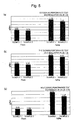
- the catalyst apparatus 100 (sample 2) according to the present invention produced as described above was then attached to a compact motor cycle B and tested and evaluated, and results of the evaluation test (performance of cleaning CO, THC, and NOx (EU3: Fresh, Aging)) are shown below.
- a sample 1 which is a target compared with the sample 2, includes the catalyst carrier 2 and the catalyst metal particles 3 in both the lower catalyst layer 12L and the upper catalyst layer 12U, but no pores 15.
- the present invention is embodied based on the embodiment described above and can also be embodied based on the following technical ideas of the present invention.
- the catalyst apparatus constituent material 10 has a tubular shape and can instead have an appropriate shape in accordance with the form and other factors of the catalyst apparatus 100, in which the catalyst apparatus constituent material 10 is incorporated.
- the catalyst apparatus constituent material 10 when used as the electrode of a secondary battery, the catalyst apparatus constituent material 10 has a flat-plate-like shape.
- the honeycomb structure 13 is made of stainless steel.
- the honeycomb structure 13 may, however, be made of another material, such as ceramic.
- the honeycomb structure 13 can instead be produced by molding a ceramic material in extrusion molding to form a honeycomb structure and then baking the honeycomb structure as also shown in Figure 1 by way of example.
- the pores 15 are formed only in the lower catalyst layer 12L formed on the base 11, and the upper catalyst layer 12U having no pores 15 formed therein is the catalyst-metal-particle-containing layer, as shown in Figure 4(a) .
- the pores 15 can be formed both in the lower catalyst layer 12L and the upper catalyst layer 12U, as shown in Figure 4(b) , or the pores 15 can be formed only in the upper catalyst layer 12U and the lower catalyst layer 12L having no pores 15 formed therein is the catalyst-metal-particle-containing layer, as shown in Figure 4(c) .
- the pore networks 15N formed in the separate layers communicate with each other and are connected to each other.
Landscapes
- Chemical & Material Sciences (AREA)
- Engineering & Computer Science (AREA)
- Chemical Kinetics & Catalysis (AREA)
- Health & Medical Sciences (AREA)
- Combustion & Propulsion (AREA)
- Materials Engineering (AREA)
- Organic Chemistry (AREA)
- Toxicology (AREA)
- Mechanical Engineering (AREA)
- General Engineering & Computer Science (AREA)
- Ceramic Engineering (AREA)
- Physics & Mathematics (AREA)
- Thermal Sciences (AREA)
- Environmental & Geological Engineering (AREA)
- Analytical Chemistry (AREA)
- General Chemical & Material Sciences (AREA)
- Oil, Petroleum & Natural Gas (AREA)
- Biomedical Technology (AREA)
- Catalysts (AREA)
- Exhaust Gas After Treatment (AREA)
- Exhaust Gas Treatment By Means Of Catalyst (AREA)
Applications Claiming Priority (2)
| Application Number | Priority Date | Filing Date | Title |
|---|---|---|---|
| JP2019058244 | 2019-03-26 | ||
| PCT/JP2020/004923 WO2020195237A1 (fr) | 2019-03-26 | 2020-02-07 | Matériau de formation de couche de catalyseur, matériau constitutif de dispositif de catalyseur, dispositif de catalyseur et leurs procédés de production |
Publications (2)
| Publication Number | Publication Date |
|---|---|
| EP3795251A1 true EP3795251A1 (fr) | 2021-03-24 |
| EP3795251A4 EP3795251A4 (fr) | 2021-06-09 |
Family
ID=72611890
Family Applications (1)
| Application Number | Title | Priority Date | Filing Date |
|---|---|---|---|
| EP20779804.2A Pending EP3795251A4 (fr) | 2019-03-26 | 2020-02-07 | Matériau de formation de couche de catalyseur, matériau constitutif de dispositif de catalyseur, dispositif de catalyseur et leurs procédés de production |
Country Status (5)
| Country | Link |
|---|---|
| US (1) | US11867109B2 (fr) |
| EP (1) | EP3795251A4 (fr) |
| JP (1) | JP6913873B2 (fr) |
| CN (1) | CN113543880B (fr) |
| WO (1) | WO2020195237A1 (fr) |
Families Citing this family (1)
| Publication number | Priority date | Publication date | Assignee | Title |
|---|---|---|---|---|
| JP7328192B2 (ja) * | 2020-10-06 | 2023-08-16 | トヨタ自動車株式会社 | 排ガス浄化装置 |
Family Cites Families (14)
| Publication number | Priority date | Publication date | Assignee | Title |
|---|---|---|---|---|
| JPH07256116A (ja) * | 1994-03-25 | 1995-10-09 | Calsonic Corp | 触媒コンバータの金属触媒担体とその製造方法 |
| CN100542674C (zh) * | 2003-06-10 | 2009-09-23 | 揖斐电株式会社 | 蜂窝状结构体 |
| DE602004029544D1 (de) * | 2003-07-15 | 2010-11-25 | Ibiden Co Ltd | Honigwabenstrukturkörper |
| JP2005087826A (ja) | 2003-09-16 | 2005-04-07 | Nissan Motor Co Ltd | ナノハニカム触媒およびその製造方法 |
| US20080241032A1 (en) * | 2007-04-02 | 2008-10-02 | Geo2 Technologies, Inc. | Catalyzing Lean NOx Filter and Method of Using Same |
| JP5094234B2 (ja) * | 2007-06-25 | 2012-12-12 | 本田技研工業株式会社 | 排ガス浄化フィルタ及びその製造方法 |
| US8440586B2 (en) * | 2010-02-26 | 2013-05-14 | Corning Incorporated | Low pressure drop extruded catalyst filter |
| JP5872179B2 (ja) * | 2011-03-10 | 2016-03-01 | 株式会社エフ・シー・シー | 排気ガス浄化用触媒担体の製造方法 |
| JP5895600B2 (ja) * | 2012-03-01 | 2016-03-30 | 日産自動車株式会社 | 排ガス浄化触媒及びその製造方法 |
| JP2014227324A (ja) * | 2013-05-23 | 2014-12-08 | 宮川化成工業株式会社 | 多孔質セラミックス焼結体およびその製造方法 |
| JP6130423B2 (ja) * | 2015-03-27 | 2017-05-17 | トヨタ自動車株式会社 | 排ガス浄化用触媒 |
| JP6219871B2 (ja) | 2015-03-27 | 2017-10-25 | トヨタ自動車株式会社 | 排ガス浄化用触媒 |
| JP6426650B2 (ja) * | 2016-04-12 | 2018-11-21 | トヨタ自動車株式会社 | 排ガス浄化用触媒 |
| JP6442574B2 (ja) * | 2017-03-16 | 2018-12-19 | 太平洋セメント株式会社 | ナノ粒子集合体、ナノ粒子焼成物、及びこれらの製造方法 |
-
2020
- 2020-02-07 US US17/252,040 patent/US11867109B2/en active Active
- 2020-02-07 WO PCT/JP2020/004923 patent/WO2020195237A1/fr not_active Ceased
- 2020-02-07 EP EP20779804.2A patent/EP3795251A4/fr active Pending
- 2020-02-07 JP JP2020567182A patent/JP6913873B2/ja active Active
- 2020-02-07 CN CN202080002866.XA patent/CN113543880B/zh active Active
Also Published As
| Publication number | Publication date |
|---|---|
| CN113543880B (zh) | 2023-10-03 |
| CN113543880A (zh) | 2021-10-22 |
| EP3795251A4 (fr) | 2021-06-09 |
| JPWO2020195237A1 (ja) | 2021-05-20 |
| US11867109B2 (en) | 2024-01-09 |
| JP6913873B2 (ja) | 2021-08-04 |
| US20210262373A1 (en) | 2021-08-26 |
| WO2020195237A1 (fr) | 2020-10-01 |
Similar Documents
| Publication | Publication Date | Title |
|---|---|---|
| CN1097481C (zh) | 汽车尾气催化剂 | |
| AU2007263408B2 (en) | Ceramic filter | |
| CN107282043B (zh) | 排气净化用催化剂 | |
| JP2022527152A (ja) | 層状三金属触媒物品およびその触媒物品の製造方法 | |
| US20080241467A1 (en) | Mixed particles and honeycomb structure for gas conversion apparatus | |
| JP2022540561A (ja) | 層状触媒物品および触媒物品を製造する方法 | |
| JP2013521121A (ja) | 一酸化炭素変換触媒 | |
| CN114786811B (zh) | 具有富集pgm区的排放控制催化剂制品、用于生产其的方法和装置 | |
| JP6684257B2 (ja) | 排ガス浄化用ハニカム触媒 | |
| US20080004174A1 (en) | Honeycomb-shaped substrate for catalyst and catalyst for purifying exhaust gases, catalyst which uses the same | |
| CN109967071A (zh) | 废气净化催化剂 | |
| US11867109B2 (en) | Catalyst layer forming material, catalyst apparatus constituent material, catalyst apparatus, and methods for manufacturing the same | |
| US20240189771A1 (en) | Platinum-containing three-way catalyst for close-coupled engine application | |
| JP2017171543A (ja) | 多孔質セラミックス構造体 | |
| CN114728235A (zh) | 具有富集pgm区的排放控制催化剂制品 | |
| CN111132758A (zh) | 蜂窝催化剂 | |
| JPH0657320B2 (ja) | 排気ガス浄化用触媒の製造法 | |
| CN111107933A (zh) | 蜂窝催化剂 | |
| JP2019058874A (ja) | ハニカム触媒 | |
| JP2007268484A (ja) | ハニカム基材へのコート方法 | |
| JP6782571B2 (ja) | ハニカム構造体 | |
| JP4507717B2 (ja) | 排気ガス浄化用触媒 | |
| CN119097118A (zh) | 复合雾化芯及其制备方法 | |
| CN115916397A (zh) | 具有pgm梯度结构的排放控制催化剂制品 | |
| JP2019000774A (ja) | 排ガス浄化用触媒及びその製造方法 |
Legal Events
| Date | Code | Title | Description |
|---|---|---|---|
| STAA | Information on the status of an ep patent application or granted ep patent |
Free format text: STATUS: THE INTERNATIONAL PUBLICATION HAS BEEN MADE |
|
| PUAI | Public reference made under article 153(3) epc to a published international application that has entered the european phase |
Free format text: ORIGINAL CODE: 0009012 |
|
| STAA | Information on the status of an ep patent application or granted ep patent |
Free format text: STATUS: REQUEST FOR EXAMINATION WAS MADE |
|
| 17P | Request for examination filed |
Effective date: 20201218 |
|
| AK | Designated contracting states |
Kind code of ref document: A1 Designated state(s): AL AT BE BG CH CY CZ DE DK EE ES FI FR GB GR HR HU IE IS IT LI LT LU LV MC MK MT NL NO PL PT RO RS SE SI SK SM TR |
|
| AX | Request for extension of the european patent |
Extension state: BA ME |
|
| A4 | Supplementary search report drawn up and despatched |
Effective date: 20210510 |
|
| RIC1 | Information provided on ipc code assigned before grant |
Ipc: B01J 37/02 20060101AFI20210503BHEP Ipc: B01D 53/94 20060101ALI20210503BHEP Ipc: B01J 35/04 20060101ALI20210503BHEP Ipc: B01J 37/04 20060101ALI20210503BHEP Ipc: B01J 37/08 20060101ALI20210503BHEP Ipc: F01N 3/28 20060101ALI20210503BHEP |
|
| DAV | Request for validation of the european patent (deleted) | ||
| DAX | Request for extension of the european patent (deleted) | ||
| STAA | Information on the status of an ep patent application or granted ep patent |
Free format text: STATUS: EXAMINATION IS IN PROGRESS |
|
| 17Q | First examination report despatched |
Effective date: 20240322 |