EP3795332A2 - Module d'aération ainsi qu'installation de traction du fil associée - Google Patents
Module d'aération ainsi qu'installation de traction du fil associée Download PDFInfo
- Publication number
- EP3795332A2 EP3795332A2 EP20183468.6A EP20183468A EP3795332A2 EP 3795332 A2 EP3795332 A2 EP 3795332A2 EP 20183468 A EP20183468 A EP 20183468A EP 3795332 A2 EP3795332 A2 EP 3795332A2
- Authority
- EP
- European Patent Office
- Prior art keywords
- ventilation
- film
- channel
- transport
- nozzle
- Prior art date
- Legal status (The legal status is an assumption and is not a legal conclusion. Google has not performed a legal analysis and makes no representation as to the accuracy of the status listed.)
- Granted
Links
Images







Classifications
-
- B—PERFORMING OPERATIONS; TRANSPORTING
- B29—WORKING OF PLASTICS; WORKING OF SUBSTANCES IN A PLASTIC STATE IN GENERAL
- B29C—SHAPING OR JOINING OF PLASTICS; SHAPING OF MATERIAL IN A PLASTIC STATE, NOT OTHERWISE PROVIDED FOR; AFTER-TREATMENT OF THE SHAPED PRODUCTS, e.g. REPAIRING
- B29C35/00—Heating, cooling or curing, e.g. crosslinking or vulcanising; Apparatus therefor
- B29C35/002—Component parts, details or accessories; Auxiliary operations
-
- B—PERFORMING OPERATIONS; TRANSPORTING
- B29—WORKING OF PLASTICS; WORKING OF SUBSTANCES IN A PLASTIC STATE IN GENERAL
- B29C—SHAPING OR JOINING OF PLASTICS; SHAPING OF MATERIAL IN A PLASTIC STATE, NOT OTHERWISE PROVIDED FOR; AFTER-TREATMENT OF THE SHAPED PRODUCTS, e.g. REPAIRING
- B29C55/00—Shaping by stretching, e.g. drawing through a die; Apparatus therefor
- B29C55/02—Shaping by stretching, e.g. drawing through a die; Apparatus therefor of plates or sheets
- B29C55/10—Shaping by stretching, e.g. drawing through a die; Apparatus therefor of plates or sheets multiaxial
- B29C55/12—Shaping by stretching, e.g. drawing through a die; Apparatus therefor of plates or sheets multiaxial biaxial
-
- B—PERFORMING OPERATIONS; TRANSPORTING
- B29—WORKING OF PLASTICS; WORKING OF SUBSTANCES IN A PLASTIC STATE IN GENERAL
- B29C—SHAPING OR JOINING OF PLASTICS; SHAPING OF MATERIAL IN A PLASTIC STATE, NOT OTHERWISE PROVIDED FOR; AFTER-TREATMENT OF THE SHAPED PRODUCTS, e.g. REPAIRING
- B29C48/00—Extrusion moulding, i.e. expressing the moulding material through a die or nozzle which imparts the desired form; Apparatus therefor
- B29C48/25—Component parts, details or accessories; Auxiliary operations
- B29C48/88—Thermal treatment of the stream of extruded material, e.g. cooling
- B29C48/885—External treatment, e.g. by using air rings for cooling tubular films
-
- B—PERFORMING OPERATIONS; TRANSPORTING
- B29—WORKING OF PLASTICS; WORKING OF SUBSTANCES IN A PLASTIC STATE IN GENERAL
- B29C—SHAPING OR JOINING OF PLASTICS; SHAPING OF MATERIAL IN A PLASTIC STATE, NOT OTHERWISE PROVIDED FOR; AFTER-TREATMENT OF THE SHAPED PRODUCTS, e.g. REPAIRING
- B29C55/00—Shaping by stretching, e.g. drawing through a die; Apparatus therefor
- B29C55/02—Shaping by stretching, e.g. drawing through a die; Apparatus therefor of plates or sheets
- B29C55/10—Shaping by stretching, e.g. drawing through a die; Apparatus therefor of plates or sheets multiaxial
- B29C55/12—Shaping by stretching, e.g. drawing through a die; Apparatus therefor of plates or sheets multiaxial biaxial
- B29C55/16—Shaping by stretching, e.g. drawing through a die; Apparatus therefor of plates or sheets multiaxial biaxial simultaneously
- B29C55/165—Apparatus therefor
-
- B—PERFORMING OPERATIONS; TRANSPORTING
- B29—WORKING OF PLASTICS; WORKING OF SUBSTANCES IN A PLASTIC STATE IN GENERAL
- B29C—SHAPING OR JOINING OF PLASTICS; SHAPING OF MATERIAL IN A PLASTIC STATE, NOT OTHERWISE PROVIDED FOR; AFTER-TREATMENT OF THE SHAPED PRODUCTS, e.g. REPAIRING
- B29C35/00—Heating, cooling or curing, e.g. crosslinking or vulcanising; Apparatus therefor
- B29C35/02—Heating or curing, e.g. crosslinking or vulcanizing during moulding, e.g. in a mould
- B29C35/04—Heating or curing, e.g. crosslinking or vulcanizing during moulding, e.g. in a mould using liquids, gas or steam
- B29C35/045—Heating or curing, e.g. crosslinking or vulcanizing during moulding, e.g. in a mould using liquids, gas or steam using gas or flames
-
- B—PERFORMING OPERATIONS; TRANSPORTING
- B29—WORKING OF PLASTICS; WORKING OF SUBSTANCES IN A PLASTIC STATE IN GENERAL
- B29C—SHAPING OR JOINING OF PLASTICS; SHAPING OF MATERIAL IN A PLASTIC STATE, NOT OTHERWISE PROVIDED FOR; AFTER-TREATMENT OF THE SHAPED PRODUCTS, e.g. REPAIRING
- B29C35/00—Heating, cooling or curing, e.g. crosslinking or vulcanising; Apparatus therefor
- B29C35/16—Cooling
-
- B—PERFORMING OPERATIONS; TRANSPORTING
- B29—WORKING OF PLASTICS; WORKING OF SUBSTANCES IN A PLASTIC STATE IN GENERAL
- B29C—SHAPING OR JOINING OF PLASTICS; SHAPING OF MATERIAL IN A PLASTIC STATE, NOT OTHERWISE PROVIDED FOR; AFTER-TREATMENT OF THE SHAPED PRODUCTS, e.g. REPAIRING
- B29C48/00—Extrusion moulding, i.e. expressing the moulding material through a die or nozzle which imparts the desired form; Apparatus therefor
- B29C48/25—Component parts, details or accessories; Auxiliary operations
- B29C48/88—Thermal treatment of the stream of extruded material, e.g. cooling
- B29C48/91—Heating, e.g. for cross linking
-
- B—PERFORMING OPERATIONS; TRANSPORTING
- B29—WORKING OF PLASTICS; WORKING OF SUBSTANCES IN A PLASTIC STATE IN GENERAL
- B29C—SHAPING OR JOINING OF PLASTICS; SHAPING OF MATERIAL IN A PLASTIC STATE, NOT OTHERWISE PROVIDED FOR; AFTER-TREATMENT OF THE SHAPED PRODUCTS, e.g. REPAIRING
- B29C48/00—Extrusion moulding, i.e. expressing the moulding material through a die or nozzle which imparts the desired form; Apparatus therefor
- B29C48/25—Component parts, details or accessories; Auxiliary operations
- B29C48/88—Thermal treatment of the stream of extruded material, e.g. cooling
- B29C48/911—Cooling
-
- B—PERFORMING OPERATIONS; TRANSPORTING
- B29—WORKING OF PLASTICS; WORKING OF SUBSTANCES IN A PLASTIC STATE IN GENERAL
- B29C—SHAPING OR JOINING OF PLASTICS; SHAPING OF MATERIAL IN A PLASTIC STATE, NOT OTHERWISE PROVIDED FOR; AFTER-TREATMENT OF THE SHAPED PRODUCTS, e.g. REPAIRING
- B29C55/00—Shaping by stretching, e.g. drawing through a die; Apparatus therefor
- B29C55/02—Shaping by stretching, e.g. drawing through a die; Apparatus therefor of plates or sheets
-
- B—PERFORMING OPERATIONS; TRANSPORTING
- B29—WORKING OF PLASTICS; WORKING OF SUBSTANCES IN A PLASTIC STATE IN GENERAL
- B29C—SHAPING OR JOINING OF PLASTICS; SHAPING OF MATERIAL IN A PLASTIC STATE, NOT OTHERWISE PROVIDED FOR; AFTER-TREATMENT OF THE SHAPED PRODUCTS, e.g. REPAIRING
- B29C55/00—Shaping by stretching, e.g. drawing through a die; Apparatus therefor
- B29C55/02—Shaping by stretching, e.g. drawing through a die; Apparatus therefor of plates or sheets
- B29C55/20—Edge clamps
-
- B—PERFORMING OPERATIONS; TRANSPORTING
- B29—WORKING OF PLASTICS; WORKING OF SUBSTANCES IN A PLASTIC STATE IN GENERAL
- B29C—SHAPING OR JOINING OF PLASTICS; SHAPING OF MATERIAL IN A PLASTIC STATE, NOT OTHERWISE PROVIDED FOR; AFTER-TREATMENT OF THE SHAPED PRODUCTS, e.g. REPAIRING
- B29C35/00—Heating, cooling or curing, e.g. crosslinking or vulcanising; Apparatus therefor
- B29C35/02—Heating or curing, e.g. crosslinking or vulcanizing during moulding, e.g. in a mould
- B29C35/04—Heating or curing, e.g. crosslinking or vulcanizing during moulding, e.g. in a mould using liquids, gas or steam
- B29C35/045—Heating or curing, e.g. crosslinking or vulcanizing during moulding, e.g. in a mould using liquids, gas or steam using gas or flames
- B29C2035/046—Heating or curing, e.g. crosslinking or vulcanizing during moulding, e.g. in a mould using liquids, gas or steam using gas or flames dried air
-
- B—PERFORMING OPERATIONS; TRANSPORTING
- B29—WORKING OF PLASTICS; WORKING OF SUBSTANCES IN A PLASTIC STATE IN GENERAL
- B29C—SHAPING OR JOINING OF PLASTICS; SHAPING OF MATERIAL IN A PLASTIC STATE, NOT OTHERWISE PROVIDED FOR; AFTER-TREATMENT OF THE SHAPED PRODUCTS, e.g. REPAIRING
- B29C35/00—Heating, cooling or curing, e.g. crosslinking or vulcanising; Apparatus therefor
- B29C35/16—Cooling
- B29C2035/1658—Cooling using gas
-
- B—PERFORMING OPERATIONS; TRANSPORTING
- B29—WORKING OF PLASTICS; WORKING OF SUBSTANCES IN A PLASTIC STATE IN GENERAL
- B29C—SHAPING OR JOINING OF PLASTICS; SHAPING OF MATERIAL IN A PLASTIC STATE, NOT OTHERWISE PROVIDED FOR; AFTER-TREATMENT OF THE SHAPED PRODUCTS, e.g. REPAIRING
- B29C35/00—Heating, cooling or curing, e.g. crosslinking or vulcanising; Apparatus therefor
- B29C35/16—Cooling
- B29C2035/1658—Cooling using gas
- B29C2035/1666—Cooling using gas dried air
-
- B—PERFORMING OPERATIONS; TRANSPORTING
- B29—WORKING OF PLASTICS; WORKING OF SUBSTANCES IN A PLASTIC STATE IN GENERAL
- B29L—INDEXING SCHEME ASSOCIATED WITH SUBCLASS B29C, RELATING TO PARTICULAR ARTICLES
- B29L2007/00—Flat articles, e.g. films or sheets
-
- B—PERFORMING OPERATIONS; TRANSPORTING
- B29—WORKING OF PLASTICS; WORKING OF SUBSTANCES IN A PLASTIC STATE IN GENERAL
- B29L—INDEXING SCHEME ASSOCIATED WITH SUBCLASS B29C, RELATING TO PARTICULAR ARTICLES
- B29L2007/00—Flat articles, e.g. films or sheets
- B29L2007/002—Panels; Plates; Sheets
-
- B—PERFORMING OPERATIONS; TRANSPORTING
- B29—WORKING OF PLASTICS; WORKING OF SUBSTANCES IN A PLASTIC STATE IN GENERAL
- B29L—INDEXING SCHEME ASSOCIATED WITH SUBCLASS B29C, RELATING TO PARTICULAR ARTICLES
- B29L2007/00—Flat articles, e.g. films or sheets
- B29L2007/008—Wide strips, e.g. films, webs
Definitions
- the invention relates to a ventilation module, in particular for stretching systems for plastic films according to the preamble of claim 1, as well as a stretching system with such a ventilation module.
- Ventilation modules are also used in the manufacture of plastic films, among other things. They are used to heat, warm or cool web-shaped materials, in particular a plastic film to be stretched.
- the ventilation nozzle is often arranged transversely, ie generally perpendicular to the outflow direction of the material web and thus transversely to the longitudinal direction of the web, above and / or below the material web. If ventilation nozzles of this type are used in film stretching systems, the film stretching system can be a monoaxial longitudinal, monoaxial transverse or sequential or simultaneous longitudinal and transverse stretching system.
- the uniformity of the outflow and the uniformity of the temperature distribution of the outflowing air flow is particularly important for the film stretching process, since uneven heating of a plastic film during processing can have negative effects on the thickness profile and the structure of the plastic film and thus on its quality and quality. Slight areas of heat are stretched more, for example, which means that they can be thinner than, for example, colder areas of plastic film. Uniform ventilation is particularly important in the production of very thin plastic films and foils.
- Ventilators are known from the prior art. Such ventilation modules are often also referred to as ventilation nozzles. From the DE 196 23 471 C1 a ventilation nozzle is known which is constructed in the form of a perforated nozzle. A multitude of holes arranged in a row, both in the withdrawal direction as well as are offset transversely to the take-off direction, is penetrated by a volume of air, which is fed to the plastic film web via a multi-chamber system.
- nozzle boxes above and below the moving material web in particular in the form of a plastic film, which comprise telescopic nozzles and in particular telescopic slot nozzles, via which the moving material web can be subjected to an air stream.
- the slot nozzles can be adjusted to a certain extent in relation to the nozzle body or nozzle channel in the direction of the material plane or away from it.
- the object of the present invention to create an improved ventilation module with associated nozzles, which eliminates the disadvantages of the prior art and in particular also larger adjustment ranges with regard to the different required wide material webs allowed.
- the material web width is ultimately understood to mean the working width or also the film width. The corresponding terms are sometimes used in parallel.
- the improved ventilation module should also enable an improved temperature distribution in the plane of the material web.
- the nozzle according to the invention can extend over a complete ventilation zone without having to provide intermediate nozzle areas in which suction must take place.
- the nozzle itself is located somewhat further above the transport system carrying the movable clips or the housing of a transport system channel.
- the nozzle outlet openings are closed in the area above the material web to be processed without any gaps in the direction of movement of the material web.
- the air or gas recirculation openings are located in the area between the clips that engage laterally on the edge of the material web. At least one nozzle return opening can be so close to the moving material web and in particular to the Moving plastic film web lie that the distance between the actual nozzle return opening and the material web is less than the distance from the most distant point of a clip or clip part, for example in the form of a clip lever up to the level of the material web. This makes it possible for the gas or air flow supplied to the material web to be discharged directly in the desired and set temperature range of the material web to be heated, heated or cooled, without the temperature being falsified by the cooling clips themselves or by undesired turbulence comes, which can lead to strong undesirable temperature differences.
- the ventilation module according to the invention with the associated nozzle can be adjusted in width without any problems in further areas without having to give up the advantages according to the invention.
- the blown air it is possible for the blown air to be sucked back in a targeted manner between the clips and not in the general space above the material web, in which fresh, heated or cooled air is also supplied in the direction of the material web. This automatically prevents an exchange of temperature between the air flowing around the film and the colder clips or adjacent walls.
- the function of a ventilation module and thus of the ventilation module according to the invention with slot or hole nozzles, in particular for an oven with a continuous web of goods or material is to heat the corresponding web of goods or material, in particular in the form of a plastic film to be stretched, to cool down and / or to maintain a constant temperature in the area of this web of material or material, it being possible for the material or material web to vary in thickness.
- the nozzle outlet direction is directed perpendicularly or obliquely to the web of goods or material, the ventilation nozzles being arranged above and / or below the web of goods or material.
- a ventilation module according to the invention is explained in connection with an exemplary stretching system, the stretching system being primarily explained using a simultaneous stretching system, although in principle a corresponding ventilation module according to the invention can also be used for other moving material webs in general and for a stretching system in particular, which for example only can consist of a monoaxial longitudinal stretching system, a monoaxial transverse stretching system or a sequential longitudinal and transverse stretching system in which a material web, in particular the plastic film, is stretched first in the longitudinal and then in the transverse direction or vice versa, first in the transverse and then in the longitudinal direction.
- a simultaneous stretching system explained by way of example has two symmetrically designed drive systems which lie symmetrically to a central symmetry plane SE running vertically to the film plane.
- the two drive systems arranged symmetrically to the plane of symmetry SE in the haul-off direction 1 with the associated circumferential movement path are shown, with the material web F to be treated, ie to be stretched, in particular in the form of a Plastic film F is moved along the take-off direction 1 through it, for which purpose clips are used that grip the film edge and move the film through the stretching system.
- the plastic melt is released from a nozzle or extruder nozzle, usually onto a cooling roller, which is also referred to as a chill roll.
- a cooling roller which is also referred to as a chill roll.
- a so-called “cast film” has formed, which then usually runs into an oven to control the temperature of the film.
- the term "cast film” is usually no longer used, but only a “film” or "plastic film”.
- the term "foil” is often used.
- a film F to be stretched runs into the stretching system in an inlet area ER, the two material web or film edges 5 then being gripped by clips K circulating on the closed webs 2, clips being shown in the cross-sectional view using, for example Figure 2 are shown.
- the film F is then heated, for example, in a subsequent preheating zone PH and then fed to a stretching zone R in order to be stretched here simultaneously in the longitudinal and transverse directions.
- the Clamps are accelerated to a higher stretching speed v2 compared to the drive speed v1 in the entry area in order to stretch the plastic film simultaneously in the longitudinal and transverse directions.
- the clips are moved away from each other on diverging track sections, with the distance x between two successive clips as well as the distance y between the clips increasing, as is the case on the associated paths on the drive side on the one hand and on the operator side on the other are moved, so the distance y between the opposite side edges of the plastic film increases.
- joints G By means of joints G, the course of the guideway 2 can be adjusted, especially in the area of the stretching zone, in accordance with the desired and optimal specifications.
- the guide rails can also run through an oven O.
- the film has a speed v2 that is higher than the speed v1.
- the stretched film F then generally passes through at least one heat treatment zone HT, ie a so-called annealing zone, in which relaxation can take place.
- the speed v2 is slowed down and the distance x between each successive clip is reduced.
- the distance y from opposing clips can be reduced.
- the speeds are thereby reduced to the extent of the desired relaxation.
- the film is advantageously subjected to relaxation.
- This relaxation can take place in the longitudinal direction, in the transverse direction or in both directions. It is preferably carried out both in the longitudinal and in the transverse direction.
- a method is therefore preferred which is characterized in that, after the simultaneous stretching, relaxation is carried out in the longitudinal direction or in the transverse direction or in both directions. This means that the film is allowed to shrink in a controlled manner.
- the extent of relaxation is usually between 2% and 12%, preferably between 4% and 8% and very particularly preferably 5% to 7%, depending on the length and / or the width of the film.
- the film is unfolded by suitable means and then leaves the simultaneous stretching system.
- FIG. 2 So a clip transport unit T can be seen, which a so-called clip part 6 and the so-called transport part 7 includes.
- the clip part 6 is connected to the transport part 7 via a so-called bridge 8.
- the clip bridge 8 can be added to the transport or clip part.
- the clip part 6 comprises a clip lever 25c which can be pivoted about a clip axis 25b and which is sometimes also referred to as a knife flap 25c.
- a film F is fixed, i.e., pinched and held, between the gripping surface 25d and a clamp table 25e.
- a pear-shaped or U-shaped closing part 25g ensures the opening and closing of the clamp lever and thus the clamping or releasing of the film together with a corresponding prior art device (not shown).
- the opening and closing can take place purely mechanically or magnetically, depending on the design of the closing part.
- At least one pair of rollers 505 run on each running surface, namely a pair of rollers 505a lying on top, which rotate around a horizontal axis and on one upwards Unroll facing running surface 15a. The entire weight of the associated transport part with the clip part connected to it is absorbed and supported via this pair of rollers.
- a pair of rollers 505b rolling on the lower running surface 15b is only used for safety when running.
- a pair of rollers 505c and opposite a pair of rollers 505d are also provided on the clip side, which roll on the relevant vertical running surfaces 15c and 15d.
- the transport part 7 is guided and stored above it.
- the corresponding guide rail 15 is held at intervals by a plurality of horizontal supports offset in the longitudinal direction of the guide rail, each of which runs in the free space 401 between the upper and lower running wheel 505d located away from the clip and is firmly connected to the guide rail.
- the rail system and support elements of the rollers can also be designed completely differently.
- sliding elements could also be used instead of the rollers and the guide rail itself could, as is known in the prior art, also be designed completely differently.
- the corresponding transport part is driven by linear motors which comprise stationary primary parts 502 and secondary parts 503 which can move with the clip transport parts T.
- linear motors which comprise stationary primary parts 502 and secondary parts 503 which can move with the clip transport parts T.
- the clips ie the clip 6 with the transport parts 7 by means of the primary parts 502 and the secondary parts 503 are moved and moved longitudinally.
- the aforementioned primary parts 502 are attached parallel to the guide and support rail 15.
- the secondary parts 503 consist of the aforementioned permanent magnets 503a, which are fastened in a respective holding cage 503b, which in turn is held on the clip body 6.
- a (small) spacing gap Sp is formed between the primary and secondary parts 502, 503, through which the electromagnetic waves generated by the primary part act on the permanent magnet 503a on the transport part and thereby move the transport part in the feed direction.
- the film is stretched, for example, with such a linear motor-driven simultaneous stretching system.
- a simultaneous stretching system can also be used, which works by means of a pantograph system.
- the solution according to the invention can not only be implemented in a simultaneous stretching system, but rather also with a purely longitudinal or purely transverse stretching system or with a sequential longitudinal and transverse stretching system in which the film is stretched first in the longitudinal and then in the transverse direction or vice versa, first in the transverse and then in the longitudinal direction. In that case it would Figure 1 only reproduce the transverse stretching stage.
- the solution according to the invention is not only possible with a stretching system, but also when, for example, the film is moved in parallel without stretching, in particular passed through an oven in parallel.
- Figure 3 Reference shows a spatial view of a section from a corresponding stretching system, namely a leading section in which a plastic film has not yet stretched in the transverse direction or not yet by means of a simultaneous stretching system or a sequential stretching system in the transverse direction.
- the film or plastic film F therefore still has a relatively narrow width.
- the two lateral transport system channels 35 are shown, in which the based on Figure 2 reproduced transport parts 7 can be moved on the corresponding guide and / or support rail 15 and, in the construction shown, carry the actual clip part 6 via a bridge part B.
- the term movable clips K is also briefly referred to below with regard to the clip part 6 with the associated transport part.
- the transport system channels 35 are designed in the manner of a housing. These are the two transport system channel housing 35a in Figure 3 shown, which are arranged to the left and right of the moving material web F. According to Figure 3
- the transport system duct housings 35a each have a top side, a bottom side, distant outer sides and an inner side 35b facing the moving material web F, which is also sometimes referred to below as the transport system shielding wall 35b.
- the corresponding transport system channels 35 with the associated transport system channel housing 35a is also off Figure 2 can be seen in the cross-sectional view, in this embodiment according to Figure 2 in the transport duct housing 35a only the guide and transport rail 15 for the forward movement of the clips K in the withdrawal direction 1 are accommodated and the space for the cable ducts and terminal boxes has been omitted for the sake of simplicity.
- the rail system for the return path is provided or accommodated outside of this channel housing arrangement 35a in a separate channel.
- each of the two transport system channels 35 has a column-shaped opening 37 through which the connecting part 8, designated as bridge B, protrudes and protrudes between the actual clip part 6 and the transport part 7 in the direction of the film.
- the clips K are shown in the closed state, in which they grip the opposite edges 5 of a film F and are moved or driven in the withdrawal direction 1 through the system.
- FIG Figure 4 reproduced in cross section, in which the two lateral transport system channels 35 are shown, which hold the rail system with the transport part 7 and the clip part 6 held over the bridge B, which hold a film F between their clip table and the lower end of the clip lever.
- the two lateral transport system channels 35 and the ventilation nozzles 41 form the ventilation space BE.
- the two transport system channels 35 must be further removed from one another, for example in accordance with the arrows 39 shown in the opposite direction. Then films with a wider film width than in Figure 4 are processed because the in Figure 4 shown, the respective lateral film edges gripping clips are then more distant from one another and can hold a wider film F clamped between them and move it in the take-off direction 1.
- a corresponding ventilation nozzle 41 is above the film and a ventilation nozzle 41 below the film arranged, ie even above and below the transport system channels 35 and thus above and below the transport system channel housing 35c and 35d.
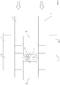
- the air instabilities also occur because in the same space in which the film F is moved, not only does the temperature-controlled air flow in according to the arrow 141, but also in turn flows out in the opposite direction according to the arrows 143, to then flow in the space between the individual ventilation nozzles 41 to flow to the not shown above-lying return suction channels.
- Ventilation module according to the invention
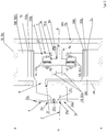
- FIGS. 5a and 5b each show two cross-sectional representations through an upper ventilation module according to the invention, namely a vertical cross-section through two transport system channels 35 which run parallel to one another and are arranged at a lateral distance from one another. In between runs the corresponding film F to be fed through the system and to be stretched.
- the cross-sectional view is thus shown transversely and in particular perpendicular to the two guide and transport rails 15, these rails 15 and the actual transport units 7 not being shown in detail. In this respect, reference is made to the previous explanations and illustrations of known solutions.
- the associated transport system channels 35 with the associated movable clips K are set in such a way that they hold, for example, a narrow film F with a relatively small film width at the film edges 5 and guide it through the stretching system in the take-off direction 1.
- the ventilation module according to the invention is also set differently, which will be discussed below.
- the upper ventilation module When presented in accordance with Figure 5a the upper ventilation module is shown with an upper ventilation nozzle 51, which has a suitable, for example, in Figure 5a has ventilation nozzle feed opening 53 on the right, so that a correspondingly tempered or, depending on the application, also cooled air or gas flow, usually ambient air (which also consist of other gases or gaseous media or can be mixed with other gaseous media), accordingly the arrows 55 can be supplied.
- ambient air which also consist of other gases or gaseous media or can be mixed with other gaseous media
- the corresponding air or gas flow can be blown into a central section 57 (ventilation or ventilation nozzle chamber 57) which has an outlet opening 59 which is preferably oriented in the direction of the film F.
- the gas or air flow can then flow out in the direction of the film F via a subsequent ventilation duct or ventilation nozzle duct 61 (which is also sometimes referred to below as ventilation outlet duct 61) in accordance with the flow arrows 63 there.
- the gas or air flow is fed to the aeration nozzle or ventilation outlet channel 61 via a gas flow inlet side 61c, the gas flow then being able to flow on after flowing through the ventilation outlet channel at its nozzle outlet opening 62 via the gas flow outlet side 61d thus formed in the direction of film F.
- the actual nozzle outlet opening 62 lies in the distance region of the clips K, ie in the exemplary embodiment shown even at a smaller distance X from the film plane E, which is smaller than a distance XX between the furthest one Location of the cover 35c and the film plane E.
- this distance between the film plane E and the section of the associated cover 35c which is furthest away from the film plane E is designated by XX.
- the temperature-controlled air flows directly onto the film F and thus the film plane E without being cooled by the mass of the clip bodies, if these mainly have a temperature-controlled gas flow that differs from the temperature of the film.
- the gas or air flow fed to the film can then flow laterally between two clips following one another in the withdrawal direction, specifically in the direction of the flow arrows 67.
- a corresponding gas flow (heated or unheated and preferably consisting of air) can be fed to the ventilation module from the so-called air inflow side on one side through the mentioned ventilation supply opening 53 or on the two opposite sides of the ventilation module (i.e. on both sides), from where the gas - Or air flow then evenly passes into the nozzle chamber 57 mentioned. From there, the gas or air flow can flow uniformly over the entire nozzle width and length, ie over the entire available cross section of the so-called outlet openings 59 from the ventilation chamber 57 into the actual ventilation outlet channel 61.
- the so-called outlet openings 59 thus form the nozzle inlet openings 59 for the ventilation outlet channel 61.
- the outlet opening 59 of the ventilation chamber 57 is - as will be discussed later - designed so that it has a plurality of slots and / or holes.
- the gas or air stream can then continue to flow to the nozzle outlet opening 62 in order to exit there in the direction of the film F, at the level of the clips K or clip parts 6.
- This outflow movement can therefore be more or less unimpeded between the clip bodies in the direction of film F and film plane E. Reflected by the film F, the gas or air flow is then sucked off between the clips (which are a certain distance from one another in the direction of movement, ie the withdrawal direction) over the edge of the film in the direction of the suction nozzle, which will be discussed later.
- a spacing space 43 is again provided between the top or cover side 35c of the transport system channels 35 (i.e. the side that is remote from the film plane F) and the material web or film side 51a of the ventilation nozzle 51, so that the returned gas flow over the direction of flow is then correspondingly folded over into the spacing space 43 in accordance with the arrow representation 67, in order then to be able to flow into corresponding back suction channels 70.
- the recirculated air or gas streams flow through these back suction channels 70 and can go up to an upper section of the exemplary embodiment shown Figure 5a reach the upper suction nozzle 71 or chamber.
- the recirculated gas or air flow can be guided further according to the correspondingly reproduced arrows 72, for example to a heating device 73 (if there is temperature control, that is to say heating or heating is provided for the gas flow; otherwise a cooling device 73 would have to be provided here) in order to then feed the gas or air flow, which has been brought back to the appropriate temperature - which will be discussed later - via appropriate fan devices, for example again to the ventilation nozzle feed opening 53, so that the gas flow then again in the sense described is fed to the ventilation channel 51 via the flow direction 55.
- a heating device 73 if there is temperature control, that is to say heating or heating is provided for the gas flow; otherwise a cooling device 73 would have to be provided here
- a corresponding ventilation nozzle is then also preferably arranged in a mirror-inverted manner corresponding to the height of the film plane E with reference to the transport system channels 35 on the underside of the film F, as shown schematically on the basis of FIG Figure 5c is shown.
- the ventilation nozzle with its actual ventilation outlet channel 61 protruding in the direction of the film F is at least divided into two parts and a ventilation channel section 61a, which, for example, in relation to the take-off direction 1 or in relation to the material web or the plastic film film F, the clips K (or clip part 6) lying on the left of the movable clips K on the left with the associated transport system channel 35 on the left.
- Section 61b is then on the opposite side to the web of material or film F, that is, with reference to the cross-sectional illustration according to FIG Figure 5b arranged on the right side of the web of material or film F, and assigned to the clips K located on the right or movable on the right side and the transport system channel 35 located on the right. Therefore, in principle, the ventilation channel spacings 61a and 61b could also be referred to as ventilation channel halves 61a and 61b, which are preferably divided in a plane running perpendicular to the film plane and in the take-off direction 1 and are preferably arranged and / or designed in a mirror-inverted manner.
- the two ventilation outlet channel sections 61a, 61b on the side facing away from the film plane E merge into angular sections 64 running parallel to the film plane E, the angular section 64a assigned to the one ventilation outlet nozzle section 61a and the angular section 64b assigned to the opposite ventilation outlet nozzle section 61b from each other run away.
- These angular sections 64a, 64b delimit the supply opening 83 for supplying the gas and air flow from the ventilation chamber 57 to the ventilation outlet nozzle 61 in the lateral direction.
- the two ventilation channel sections 61a and 61b are preferably also adjusted to a greater or lesser extent (even if they are separate are adjustable), so that the width of the ventilation channel 61 in the transverse direction or in the perpendicular direction perpendicular to the withdrawal direction 1 then becomes significantly wider.
- the ventilation channel width B is so large that the corresponding lateral ventilation channel walls 62a and 62b (which are sometimes referred to below as ventilation channel sheets) are set or adjusted with the width setting of the transport system channels 35 so that they move in the direction of the film F facing end 62c of the ventilation channel walls 62a and 62b preferably comes to lie in the same relative position to the clips K or to the clip parts 6, as in the case of the closely spaced position of the transport system channels 35 with the associated movable clips K according to the cross-sectional illustration Figure 5a .
- a width adjustment with regard to the film and the associated ventilation nozzle can be carried out in one dimension, as was not previously possible in the prior art. Nevertheless, the supplied temperature-controlled gas flow can be supplied directly to the film F, since the actual nozzle outlet opening 62 also in the case of the width setting according to FIG Figure 5b can be arranged lying directly adjacent to the film plane E.
- these guide walls or guide plates 77 run from their fastening point 62d, preferably on the opposite outer sides of the ventilation channel sections 61a and 61b, viewed from the film plane E, diverging and then merge into a return channel 79 encompassing the spacing space 43, whose return channel 79 includes the film F. facing return channel wall 79a, for example, on the top side 35c (ceiling side 35c) of the transport system channel 35 or the transport system channel housing 35a rests directly or indirectly.
- the nozzle outlet opening 62 and thus the two ventilation duct sections 61a and 61b which can be adjusted away from or towards one another, preferably with the respectively assigned transport system duct 35 according to the arrows 39, can move away from one another or towards one another adjusted.
- the guide walls or guide plates 77 are also provided with passage openings 81, for example hole openings or slotted openings.
- these slot or gap openings 81 are provided as longitudinal slots running perpendicular to the plane of the drawing, so that the returned gas flow in accordance with the arrow representations 67 'shown from the area below these guide walls or guide plates 77 (in which the movable clips K are located) into the space above the Baffles at the in Figure 6b Flow into the return channel shown upper ventilation nozzle assembly can.
- the ventilation nozzle on the underside of the film would preferably be designed accordingly.
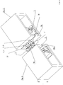
- FIG Figure 7 In order to show the actual ventilation nozzle or the ventilation outlet duct 61 in three dimensions, for example in a narrow state that has been moved together, FIG Figure 7 Referenced.
- the aforementioned passage openings 81 here in the form of slot-shaped passage openings 81, are shown in the lateral air walls or guide plates 77.
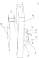
- FIG. 8a Based on Figures 8a and 8b a corresponding three-dimensional representation of a complete ventilation nozzle with an upper ventilation nozzle 51 and corresponding lower ventilation nozzle 51 'is now shown, in cross section transverse to the film plane E and transversely to the take-off direction 1 of the film F.
- the mentioned guide walls or guide plates 77 can have several, for example, one above the other through openings 81, in particular when the through openings 81 are designed in the form of slits, i.e. parallel to one another and parallel to the film plane E. Otherwise, however, they could also be transverse longitudinal slots running for this purpose or hole openings distributed over a large area with a multiplicity of gas passage openings can be provided.
- the gas passage wall 83 comprises an arrangement with one or more outlet openings 59, i.e. with one or more nozzle inlet openings 59 for the ventilation outlet channel 61, via which the gas or air flow can flow from the ventilation chamber 57 into the actual ventilation outlet channel 61.
- the outlet openings 59 and thus the nozzle inlet opening 59 in the ventilation outlet channel 61 in the gas passage wall 83 in the exemplary embodiment shown are designed in the form of a perforated grid, i.e. with a large number of individual holes offset from one another in the longitudinal and transverse directions or a large number of individual openings which that is, they are introduced into this gas passage wall 83 in the longitudinal and transverse directions.
- the corresponding air or gas passage openings 59 are arranged distributed in such an area that ensures that the corresponding gas or air flow even with the maximum width distance adjustment of the ventilation channel sections 61a and 61b according to FIG Figure 8b Can flow in as unhindered as possible over the entire width and length adjustment through this gas passage wall 83 into the actual ventilation channel 61, as is also shown with the aid of the arrows 141 arranged next to one another.
- these cover walls or cover plates 91 cover the majority of the perforated gas passage wall 83 as part of the film-side boundary wall 51a, so that a gas or air flow can flow into the actual ventilation channel 61 only via those unshielded remaining passage openings 81, i.e. through the mentioned cover walls or cover plates 91 is not closed.
- suction channels 69 mentioned several times can be provided, for example, namely in the form of a plurality of tubular channels which are arranged adjacent to one another in the withdrawal direction 1.
Landscapes
- Physics & Mathematics (AREA)
- Thermal Sciences (AREA)
- Engineering & Computer Science (AREA)
- Mechanical Engineering (AREA)
- Health & Medical Sciences (AREA)
- Oral & Maxillofacial Surgery (AREA)
- Shaping By String And By Release Of Stress In Plastics And The Like (AREA)
- Air-Flow Control Members (AREA)
Applications Claiming Priority (1)
| Application Number | Priority Date | Filing Date | Title |
|---|---|---|---|
| DE102019120794.0A DE102019120794A1 (de) | 2019-08-01 | 2019-08-01 | Belüftungsmodul sowie zugehörige Reckanlage |
Publications (4)
| Publication Number | Publication Date |
|---|---|
| EP3795332A2 true EP3795332A2 (fr) | 2021-03-24 |
| EP3795332A3 EP3795332A3 (fr) | 2021-04-14 |
| EP3795332C0 EP3795332C0 (fr) | 2024-09-04 |
| EP3795332B1 EP3795332B1 (fr) | 2024-09-04 |
Family
ID=71452004
Family Applications (1)
| Application Number | Title | Priority Date | Filing Date |
|---|---|---|---|
| EP20183468.6A Active EP3795332B1 (fr) | 2019-08-01 | 2020-07-01 | Module d'aération ainsi qu'installation de traction du fil associée |
Country Status (6)
| Country | Link |
|---|---|
| US (1) | US11759981B2 (fr) |
| EP (1) | EP3795332B1 (fr) |
| JP (1) | JP7593754B2 (fr) |
| KR (1) | KR20210015703A (fr) |
| CN (1) | CN112297408B (fr) |
| DE (1) | DE102019120794A1 (fr) |
Families Citing this family (4)
| Publication number | Priority date | Publication date | Assignee | Title |
|---|---|---|---|---|
| CN115486723A (zh) * | 2021-06-18 | 2022-12-20 | 广东美的厨房电器制造有限公司 | 喷嘴和烹饪器具 |
| KR102399283B1 (ko) * | 2021-11-01 | 2022-05-19 | 주식회사 에스티영원 | 필름 연신장비의 열풍공급용 노즐장치 및 노즐 시스템 |
| CN114161632B (zh) * | 2021-12-03 | 2022-10-28 | 连云港市金田高新材料有限公司 | 一种双向拉伸聚丙烯复合薄膜的冷却装置及冷却方法 |
| CN114368136B (zh) * | 2021-12-31 | 2024-04-23 | 苏州富强科技有限公司 | 一种气道结构及烘箱 |
Citations (3)
| Publication number | Priority date | Publication date | Assignee | Title |
|---|---|---|---|---|
| EP0455632B1 (fr) | 1987-11-02 | 1994-10-26 | E.I. Du Pont De Nemours And Company | Systeme de propulsion de moteur lineaire |
| DE4436676C2 (de) | 1994-10-13 | 1997-03-27 | Brueckner Maschbau | Verfahren zur Herstellung von längs- und/oder quergereckten, insbesondere simultan biaxial gereckten Folienbahnen |
| DE19623471C1 (de) | 1996-06-12 | 1998-02-05 | Brueckner Maschbau | Belüftungsdüse |
Family Cites Families (10)
| Publication number | Priority date | Publication date | Assignee | Title |
|---|---|---|---|---|
| DE927682C (de) * | 1951-12-06 | 1955-05-16 | Julien Dungler | Blasduese fuer Maschinen zur Behandlung von Gewebe, Papier od. dgl., wie Trockenrahmen od. dgl. |
| JP2983263B2 (ja) * | 1990-08-23 | 1999-11-29 | 日本石油化学株式会社 | 熱風循環式延伸機 |
| JP2007320276A (ja) * | 2006-06-05 | 2007-12-13 | Toray Ind Inc | テンターオーブン |
| DE102009060753A1 (de) * | 2009-12-30 | 2011-07-07 | Brückner Maschinenbau GmbH & Co. KG, 83313 | Belüftungsdüse sowie Kunststofffolienreckanlage mit zugehöriger Belüftungsdüse |
| EP2692508B1 (fr) * | 2011-03-29 | 2018-12-19 | Toray Industries, Inc. | Four de rétraction et procédé de fabrication d'un film étiré |
| JP5793914B2 (ja) * | 2011-03-31 | 2015-10-14 | 東レ株式会社 | 幅可変ノズルおよびそれを用いたテンターオーブン |
| JP6394010B2 (ja) * | 2013-03-29 | 2018-09-26 | 東レ株式会社 | テンターオーブン、及びそれを用いた熱可塑性樹脂フィルムの製造方法 |
| CN203718818U (zh) * | 2014-01-21 | 2014-07-16 | 四川川锅锅炉有限责任公司 | 一种面积可调且可摆动的二次风喷嘴 |
| MY201353A (en) * | 2017-03-28 | 2024-02-19 | Toray Industries | Air flow controller and manufacturing method of stretched film |
| CN107801356B (zh) * | 2017-10-27 | 2020-03-24 | 成都市宏山科技有限公司 | 风道可变式散热器 |
-
2019
- 2019-08-01 DE DE102019120794.0A patent/DE102019120794A1/de not_active Withdrawn
-
2020
- 2020-07-01 EP EP20183468.6A patent/EP3795332B1/fr active Active
- 2020-07-29 CN CN202010744853.1A patent/CN112297408B/zh active Active
- 2020-07-30 JP JP2020128947A patent/JP7593754B2/ja active Active
- 2020-07-30 KR KR1020200095464A patent/KR20210015703A/ko active Pending
- 2020-07-31 US US16/945,023 patent/US11759981B2/en active Active
Patent Citations (3)
| Publication number | Priority date | Publication date | Assignee | Title |
|---|---|---|---|---|
| EP0455632B1 (fr) | 1987-11-02 | 1994-10-26 | E.I. Du Pont De Nemours And Company | Systeme de propulsion de moteur lineaire |
| DE4436676C2 (de) | 1994-10-13 | 1997-03-27 | Brueckner Maschbau | Verfahren zur Herstellung von längs- und/oder quergereckten, insbesondere simultan biaxial gereckten Folienbahnen |
| DE19623471C1 (de) | 1996-06-12 | 1998-02-05 | Brueckner Maschbau | Belüftungsdüse |
Also Published As
| Publication number | Publication date |
|---|---|
| EP3795332C0 (fr) | 2024-09-04 |
| CN112297408B (zh) | 2023-03-10 |
| KR20210015703A (ko) | 2021-02-10 |
| DE102019120794A1 (de) | 2021-02-04 |
| US11759981B2 (en) | 2023-09-19 |
| CN112297408A (zh) | 2021-02-02 |
| EP3795332A3 (fr) | 2021-04-14 |
| JP2021035767A (ja) | 2021-03-04 |
| JP7593754B2 (ja) | 2024-12-03 |
| US20210031411A1 (en) | 2021-02-04 |
| EP3795332B1 (fr) | 2024-09-04 |
Similar Documents
| Publication | Publication Date | Title |
|---|---|---|
| EP3795332B1 (fr) | Module d'aération ainsi qu'installation de traction du fil associée | |
| DE69420995T2 (de) | Wellvorrichtung für Kunststoffrohre und Formblöcke | |
| EP2519396B1 (fr) | Ajutage d'aération et installation d'étirage de feuille de plastique équipée d'un ajutage d'aération | |
| EP2809496B1 (fr) | Banc d'étirage et procédé d'allongement d'une bande continue de film | |
| DE60014781T2 (de) | Anlage und Verfahren zur Vermeidung von Bandvibrationen in den Gaseinblaszonen insbesondere in den Kühlzonen | |
| DE2528370B2 (de) | Verfahren zum herstellen von biaxial verstreckten folienbahnen aus kunststoff und vorrichtung zur durchfuehrung des verfahrens | |
| EP3504363A1 (fr) | Four d'oxydation | |
| EP0464036B1 (fr) | Procede et dispositif de traitement de monofilaments | |
| DE1504507A1 (de) | Reckmaschine fuer das Querrecken thermoplastischer Kunststoffbahnen | |
| EP0907476B1 (fr) | Buse de ventilation | |
| DE2554485A1 (de) | Einem drahtwalzwerk direkt nachgeschaltetes kontrolliertes abkuehlen von warmgewalztem stahldraht, verfahren und anlage | |
| DE3703097C1 (de) | Kluppenkettenbahn fuer endlos umlaufende Spannkluppen in Spannrahmen | |
| EP3400123A1 (fr) | Dispositif et procédé de refroidissement de matériau en feuille | |
| DE102014103598A1 (de) | Bandführer für eine Strecke sowie Strecke | |
| EP0950499B1 (fr) | Procédé de fabrication de feuilles soufflées ayant des surfaces propres et dispositif pour la mise en oeuvre de ce procédé | |
| DE102021203051A1 (de) | Folienreckanlage mit behandlungszonen zum querrecken durch die anlage laufender kunststofffolien | |
| WO2022122428A1 (fr) | Dispositif de formation de mousse et appareil d'extrusion de mousse | |
| EP1232809B1 (fr) | Extrudeuse avec au moins un appareil d'extraction | |
| DE102024107021A1 (de) | Messkopf, Kantensensor sowie Anlage | |
| EP3250742B1 (fr) | Caisson d'air d'une machine d'équipement | |
| DE6803360U (de) | Vorrichtung zur behandlung von orientierten, hitzestabilisierten, thermoplastischen kunststoffolien | |
| DE102024131014A1 (de) | Kombinationsreckwerk zum Recken von Kunststofffolien | |
| DE1504443C (de) | Verfahren zur Verbesserung der physikalischen Eigenschaften von Kunststofffolienbahnen | |
| DE102023135403A1 (de) | Folienaufwickelvorrichtung, Folienherstellungsanlage sowie Verfahren zum Aufwickeln einer Folienbahn | |
| AT410077B (de) | Behandlungsvorrichtung für kunststoffextrudate |
Legal Events
| Date | Code | Title | Description |
|---|---|---|---|
| PUAI | Public reference made under article 153(3) epc to a published international application that has entered the european phase |
Free format text: ORIGINAL CODE: 0009012 |
|
| STAA | Information on the status of an ep patent application or granted ep patent |
Free format text: STATUS: THE APPLICATION HAS BEEN PUBLISHED |
|
| PUAL | Search report despatched |
Free format text: ORIGINAL CODE: 0009013 |
|
| AK | Designated contracting states |
Kind code of ref document: A2 Designated state(s): AL AT BE BG CH CY CZ DE DK EE ES FI FR GB GR HR HU IE IS IT LI LT LU LV MC MK MT NL NO PL PT RO RS SE SI SK SM TR |
|
| AX | Request for extension of the european patent |
Extension state: BA ME |
|
| AK | Designated contracting states |
Kind code of ref document: A3 Designated state(s): AL AT BE BG CH CY CZ DE DK EE ES FI FR GB GR HR HU IE IS IT LI LT LU LV MC MK MT NL NO PL PT RO RS SE SI SK SM TR |
|
| AX | Request for extension of the european patent |
Extension state: BA ME |
|
| RIC1 | Information provided on ipc code assigned before grant |
Ipc: B29C 55/12 20060101AFI20210305BHEP Ipc: B29C 55/20 20060101ALN20210305BHEP |
|
| STAA | Information on the status of an ep patent application or granted ep patent |
Free format text: STATUS: REQUEST FOR EXAMINATION WAS MADE |
|
| 17P | Request for examination filed |
Effective date: 20210416 |
|
| RBV | Designated contracting states (corrected) |
Designated state(s): AL AT BE BG CH CY CZ DE DK EE ES FI FR GB GR HR HU IE IS IT LI LT LU LV MC MK MT NL NO PL PT RO RS SE SI SK SM TR |
|
| STAA | Information on the status of an ep patent application or granted ep patent |
Free format text: STATUS: EXAMINATION IS IN PROGRESS |
|
| 17Q | First examination report despatched |
Effective date: 20221109 |
|
| RAP3 | Party data changed (applicant data changed or rights of an application transferred) |
Owner name: BRUECKNER MASCHINENBAU GMBH |
|
| GRAP | Despatch of communication of intention to grant a patent |
Free format text: ORIGINAL CODE: EPIDOSNIGR1 |
|
| STAA | Information on the status of an ep patent application or granted ep patent |
Free format text: STATUS: GRANT OF PATENT IS INTENDED |
|
| RIC1 | Information provided on ipc code assigned before grant |
Ipc: B29C 55/20 20060101ALN20240212BHEP Ipc: B29C 55/12 20060101AFI20240212BHEP |
|
| INTG | Intention to grant announced |
Effective date: 20240304 |
|
| GRAS | Grant fee paid |
Free format text: ORIGINAL CODE: EPIDOSNIGR3 |
|
| GRAA | (expected) grant |
Free format text: ORIGINAL CODE: 0009210 |
|
| STAA | Information on the status of an ep patent application or granted ep patent |
Free format text: STATUS: THE PATENT HAS BEEN GRANTED |
|
| AK | Designated contracting states |
Kind code of ref document: B1 Designated state(s): AL AT BE BG CH CY CZ DE DK EE ES FI FR GB GR HR HU IE IS IT LI LT LU LV MC MK MT NL NO PL PT RO RS SE SI SK SM TR |
|
| REG | Reference to a national code |
Ref country code: GB Ref legal event code: FG4D Free format text: NOT ENGLISH |
|
| REG | Reference to a national code |
Ref country code: CH Ref legal event code: EP |
|
| REG | Reference to a national code |
Ref country code: IE Ref legal event code: FG4D Free format text: LANGUAGE OF EP DOCUMENT: GERMAN |
|
| REG | Reference to a national code |
Ref country code: DE Ref legal event code: R096 Ref document number: 502020009075 Country of ref document: DE |
|
| U01 | Request for unitary effect filed |
Effective date: 20240911 |
|
| U07 | Unitary effect registered |
Designated state(s): AT BE BG DE DK EE FI FR IT LT LU LV MT NL PT RO SE SI Effective date: 20241002 |
|
| PG25 | Lapsed in a contracting state [announced via postgrant information from national office to epo] |
Ref country code: NO Free format text: LAPSE BECAUSE OF FAILURE TO SUBMIT A TRANSLATION OF THE DESCRIPTION OR TO PAY THE FEE WITHIN THE PRESCRIBED TIME-LIMIT Effective date: 20241204 |
|
| PG25 | Lapsed in a contracting state [announced via postgrant information from national office to epo] |
Ref country code: PL Free format text: LAPSE BECAUSE OF FAILURE TO SUBMIT A TRANSLATION OF THE DESCRIPTION OR TO PAY THE FEE WITHIN THE PRESCRIBED TIME-LIMIT Effective date: 20240904 Ref country code: GR Free format text: LAPSE BECAUSE OF FAILURE TO SUBMIT A TRANSLATION OF THE DESCRIPTION OR TO PAY THE FEE WITHIN THE PRESCRIBED TIME-LIMIT Effective date: 20241205 |
|
| PG25 | Lapsed in a contracting state [announced via postgrant information from national office to epo] |
Ref country code: HR Free format text: LAPSE BECAUSE OF FAILURE TO SUBMIT A TRANSLATION OF THE DESCRIPTION OR TO PAY THE FEE WITHIN THE PRESCRIBED TIME-LIMIT Effective date: 20240904 |
|
| PG25 | Lapsed in a contracting state [announced via postgrant information from national office to epo] |
Ref country code: ES Free format text: LAPSE BECAUSE OF FAILURE TO SUBMIT A TRANSLATION OF THE DESCRIPTION OR TO PAY THE FEE WITHIN THE PRESCRIBED TIME-LIMIT Effective date: 20240904 Ref country code: RS Free format text: LAPSE BECAUSE OF FAILURE TO SUBMIT A TRANSLATION OF THE DESCRIPTION OR TO PAY THE FEE WITHIN THE PRESCRIBED TIME-LIMIT Effective date: 20241204 |
|
| PG25 | Lapsed in a contracting state [announced via postgrant information from national office to epo] |
Ref country code: RS Free format text: LAPSE BECAUSE OF FAILURE TO SUBMIT A TRANSLATION OF THE DESCRIPTION OR TO PAY THE FEE WITHIN THE PRESCRIBED TIME-LIMIT Effective date: 20241204 Ref country code: PL Free format text: LAPSE BECAUSE OF FAILURE TO SUBMIT A TRANSLATION OF THE DESCRIPTION OR TO PAY THE FEE WITHIN THE PRESCRIBED TIME-LIMIT Effective date: 20240904 Ref country code: NO Free format text: LAPSE BECAUSE OF FAILURE TO SUBMIT A TRANSLATION OF THE DESCRIPTION OR TO PAY THE FEE WITHIN THE PRESCRIBED TIME-LIMIT Effective date: 20241204 Ref country code: HR Free format text: LAPSE BECAUSE OF FAILURE TO SUBMIT A TRANSLATION OF THE DESCRIPTION OR TO PAY THE FEE WITHIN THE PRESCRIBED TIME-LIMIT Effective date: 20240904 Ref country code: GR Free format text: LAPSE BECAUSE OF FAILURE TO SUBMIT A TRANSLATION OF THE DESCRIPTION OR TO PAY THE FEE WITHIN THE PRESCRIBED TIME-LIMIT Effective date: 20241205 Ref country code: ES Free format text: LAPSE BECAUSE OF FAILURE TO SUBMIT A TRANSLATION OF THE DESCRIPTION OR TO PAY THE FEE WITHIN THE PRESCRIBED TIME-LIMIT Effective date: 20240904 |
|
| PG25 | Lapsed in a contracting state [announced via postgrant information from national office to epo] |
Ref country code: IS Free format text: LAPSE BECAUSE OF FAILURE TO SUBMIT A TRANSLATION OF THE DESCRIPTION OR TO PAY THE FEE WITHIN THE PRESCRIBED TIME-LIMIT Effective date: 20250104 |
|
| PG25 | Lapsed in a contracting state [announced via postgrant information from national office to epo] |
Ref country code: SM Free format text: LAPSE BECAUSE OF FAILURE TO SUBMIT A TRANSLATION OF THE DESCRIPTION OR TO PAY THE FEE WITHIN THE PRESCRIBED TIME-LIMIT Effective date: 20240904 |
|
| PG25 | Lapsed in a contracting state [announced via postgrant information from national office to epo] |
Ref country code: CZ Free format text: LAPSE BECAUSE OF FAILURE TO SUBMIT A TRANSLATION OF THE DESCRIPTION OR TO PAY THE FEE WITHIN THE PRESCRIBED TIME-LIMIT Effective date: 20240904 |
|
| PG25 | Lapsed in a contracting state [announced via postgrant information from national office to epo] |
Ref country code: SK Free format text: LAPSE BECAUSE OF FAILURE TO SUBMIT A TRANSLATION OF THE DESCRIPTION OR TO PAY THE FEE WITHIN THE PRESCRIBED TIME-LIMIT Effective date: 20240904 |
|
| PLBE | No opposition filed within time limit |
Free format text: ORIGINAL CODE: 0009261 |
|
| STAA | Information on the status of an ep patent application or granted ep patent |
Free format text: STATUS: NO OPPOSITION FILED WITHIN TIME LIMIT |
|
| 26N | No opposition filed |
Effective date: 20250605 |
|
| U20 | Renewal fee for the european patent with unitary effect paid |
Year of fee payment: 6 Effective date: 20250728 |
|
| REG | Reference to a national code |
Ref country code: CH Ref legal event code: H13 Free format text: ST27 STATUS EVENT CODE: U-0-0-H10-H13 (AS PROVIDED BY THE NATIONAL OFFICE) Effective date: 20260224 |
|
| GBPC | Gb: european patent ceased through non-payment of renewal fee |
Effective date: 20250701 |
|
| PG25 | Lapsed in a contracting state [announced via postgrant information from national office to epo] |
Ref country code: GB Free format text: LAPSE BECAUSE OF NON-PAYMENT OF DUE FEES Effective date: 20250701 |
|
| PG25 | Lapsed in a contracting state [announced via postgrant information from national office to epo] |
Ref country code: CH Free format text: LAPSE BECAUSE OF NON-PAYMENT OF DUE FEES Effective date: 20250731 |