EP3795431A1 - Dispositif de verrouillage pour un composant fonctionnel, unité fonctionnelle pour un véhicule ainsi que procédé de support non destructif pour un mouvement d'un composant fonctionnel - Google Patents
Dispositif de verrouillage pour un composant fonctionnel, unité fonctionnelle pour un véhicule ainsi que procédé de support non destructif pour un mouvement d'un composant fonctionnel Download PDFInfo
- Publication number
- EP3795431A1 EP3795431A1 EP20195281.9A EP20195281A EP3795431A1 EP 3795431 A1 EP3795431 A1 EP 3795431A1 EP 20195281 A EP20195281 A EP 20195281A EP 3795431 A1 EP3795431 A1 EP 3795431A1
- Authority
- EP
- European Patent Office
- Prior art keywords
- evasive
- locking
- housing
- component
- assembly
- Prior art date
- Legal status (The legal status is an assumption and is not a legal conclusion. Google has not performed a legal analysis and makes no representation as to the accuracy of the status listed.)
- Granted
Links
Images



Classifications
-
- B—PERFORMING OPERATIONS; TRANSPORTING
- B60—VEHICLES IN GENERAL
- B60R—VEHICLES, VEHICLE FITTINGS, OR VEHICLE PARTS, NOT OTHERWISE PROVIDED FOR
- B60R25/00—Fittings or systems for preventing or indicating unauthorised use or theft of vehicles
- B60R25/01—Fittings or systems for preventing or indicating unauthorised use or theft of vehicles operating on vehicle systems or fittings, e.g. on doors, seats or windscreens
- B60R25/02—Fittings or systems for preventing or indicating unauthorised use or theft of vehicles operating on vehicle systems or fittings, e.g. on doors, seats or windscreens operating on the steering mechanism
- B60R25/021—Fittings or systems for preventing or indicating unauthorised use or theft of vehicles operating on vehicle systems or fittings, e.g. on doors, seats or windscreens operating on the steering mechanism restraining movement of the steering column or steering wheel hub, e.g. restraining means controlled by ignition switch
- B60R25/0211—Fittings or systems for preventing or indicating unauthorised use or theft of vehicles operating on vehicle systems or fittings, e.g. on doors, seats or windscreens operating on the steering mechanism restraining movement of the steering column or steering wheel hub, e.g. restraining means controlled by ignition switch comprising a locking member radially and linearly moved towards the steering column
-
- B—PERFORMING OPERATIONS; TRANSPORTING
- B60—VEHICLES IN GENERAL
- B60R—VEHICLES, VEHICLE FITTINGS, OR VEHICLE PARTS, NOT OTHERWISE PROVIDED FOR
- B60R25/00—Fittings or systems for preventing or indicating unauthorised use or theft of vehicles
- B60R25/01—Fittings or systems for preventing or indicating unauthorised use or theft of vehicles operating on vehicle systems or fittings, e.g. on doors, seats or windscreens
- B60R25/02—Fittings or systems for preventing or indicating unauthorised use or theft of vehicles operating on vehicle systems or fittings, e.g. on doors, seats or windscreens operating on the steering mechanism
- B60R25/021—Fittings or systems for preventing or indicating unauthorised use or theft of vehicles operating on vehicle systems or fittings, e.g. on doors, seats or windscreens operating on the steering mechanism restraining movement of the steering column or steering wheel hub, e.g. restraining means controlled by ignition switch
-
- B—PERFORMING OPERATIONS; TRANSPORTING
- B60—VEHICLES IN GENERAL
- B60R—VEHICLES, VEHICLE FITTINGS, OR VEHICLE PARTS, NOT OTHERWISE PROVIDED FOR
- B60R25/00—Fittings or systems for preventing or indicating unauthorised use or theft of vehicles
- B60R25/01—Fittings or systems for preventing or indicating unauthorised use or theft of vehicles operating on vehicle systems or fittings, e.g. on doors, seats or windscreens
- B60R25/04—Fittings or systems for preventing or indicating unauthorised use or theft of vehicles operating on vehicle systems or fittings, e.g. on doors, seats or windscreens operating on the propulsion system, e.g. engine or drive motor
- B60R25/06—Fittings or systems for preventing or indicating unauthorised use or theft of vehicles operating on vehicle systems or fittings, e.g. on doors, seats or windscreens operating on the propulsion system, e.g. engine or drive motor operating on the vehicle transmission
Definitions
- the invention relates to a locking device for a functionally essential component of a vehicle, in particular for a steering gear, a functional unit for a vehicle and a method for non-destructive support of a movement of a functionally essential component of a vehicle.
- Locking devices for functionally essential components of vehicles are known in principle from the prior art. These are mostly safety devices through which the functionally essential component can be locked in a certain position so that the vehicle cannot easily be moved by an unauthorized person.
- Such devices are used, for example, to lock steering columns or gear shift levers. Furthermore, such devices often have a movably mounted locking bolt, which is transferred with the aid of a gear between a locking position for locking the functionally essential component and an unlocking position for unlocking the functionally essential component. In the locking position, the locking bolt normally engages between two teeth of a gear-like element of the interlocking component in order to prevent movement, in particular in the form of a rotation of the functionally essential component. If the functionally essential component is nevertheless moved, a transverse force is transmitted through the teeth to the locking pin, so that it is loaded in the direction of a tilting movement. The locking bolt is supported on a guide, which can be damaged under high loads.
- a locking device for a functionally essential component of a vehicle has a locking element for locking the functionally essential component and a mounting housing.
- the locking element for locking the functionally essential component is movably arranged in the assembly housing.
- the assembly housing can also be at least partially assembled with a free space to form a component housing for the functionally essential component.
- the assembly housing has a rigid housing section and an evasive element.
- the evasive element is movably arranged on the rigid housing section in order to evade a tilting movement of the locking element, in particular the locking element, in the direction of the free space from a rest position into an evasive position.
- the functionally essential component can be, for example, a steering column or a switching device, in particular in the form of a gearshift lever.
- a steering wheel or gear lock can be made available by the locking device.
- the locking element can preferably be a locking pin.
- the locking element can be adjustable between a locking position and an unlocking position in order to lock the functionally essential component in the locking position, in particular in its function, and to release it in the unlocking position.
- the locking element can be linearly movable in one direction of movement between the locking position and the unlocking position.
- the component housing can in particular at least partially or completely surround the functionally essential component.
- the component housing can be a housing of the functionally essential component.
- the assembly housing in which the locking element can be moved can in particular have a plurality of housing sections.
- further components of the locking device can be arranged in the assembly housing.
- the blocking element can be protected from environmental influences and / or from a be protected from unauthorized interference. It is conceivable that the assembly housing can be at least partially mounted in the component housing of the functionally essential component, so that the free space is formed between the component housing and the assembly housing.
- the free space can in particular be understood to mean a space that is free of components.
- the free space is preferably a gap between the component housing and the assembly housing.
- the free space can have a width between the assembly housing and the component housing of less than 1 mm and / or greater than or equal to 0.1 mm, particularly preferably between 0.1 mm and 0.7 mm.
- the component housing in particular can be used to protect the functionally essential component and / or part of the locking device at least partially from environmental influences.
- the rigid housing section can in particular be arranged and / or fastened rigidly to the component housing.
- the assembly housing can preferably be at least partially inserted into an assembly interface, i.e. preferably an opening in the component housing, in the component housing.
- the evasive element By means of the evasive element, in particular a transmission of force from the locking element to the rigid housing section can be avoided or reduced. This can make it possible for the locking element not to be supported on the rigid housing section during the tilting movement of the locking element, so that this is also not damaged.
- the evasion of the evasive element into the evasive position in the direction of the free space can in particular be understood to mean that the evasive element presents no or only a minor resistance to the blocking element.
- the evasive element can thus be moved from the rest position into the evasive position by the locking element.
- the evasive element can be pushed by the blocking element from the rest position into the evasive position.
- a flexible housing section can thus be created by the evasive element. The flexible housing section can thus improve load absorption within the locking device and / or on the functionally essential component.
- the movement and / or loading of the locking element can thus be absorbed without damaging or destroying the mounting housing.
- it can thereby be avoided that, for example, parts of the assembly housing break and damage or block the functionally essential component.
- a movement of the functionally essential component can thereby be avoided even under high loads, so that the safety of the vehicle can be improved overall.
- the evasive element is formed by an insert part that is separate from the rigid housing section.
- the separate insert part can in particular be understood to mean a component that is separate from the rigid housing section.
- the separate insert can be flexibly attached to the rigid housing section or loosely attached to the rigid housing section.
- the evasive element can preferably be designed in such a way that it can only be arranged in one orientation on the rigid housing section in order to simplify assembly of the evasive element on the rigid housing section.
- the assembly housing has a locking element guide for guiding the locking element, in particular along a direction of movement of the locking element, which can be inserted into the component housing so that the free space is formed between the locking element guide and the component housing, in particular where the evasive element in the rest position forms a housing part of the locking element guide through which the locking element can be guided at least in some areas.
- the locking element guide can in particular have a guide channel in which the locking element can move between the locking position and the unlocking position.
- the free space can arise in particular in that the locking element guide is inserted into the component housing of the movable component and, in particular, is then fastened.
- the free space can thus include a play between the locking element guide and the component housing.
- the free space can therefore the assembly of the locking element guide in the component housing can be simplified and / or made possible.
- the evasive element can preferably form a lower housing part of the locking element guide. If the locking element tilts due to a movement of the functionally essential component and in particular is pressed against an edge of the locking element guide, the risk of breakage can consequently be reduced or avoided by arranging the evasive element in this area.
- the evasive element thus preferably replaces, in particular, a highly stressful housing part of the locking element guide.
- the evasive element has a hinge section with which the evasive element is mounted on the rigid housing section, in particular pivotably.
- the hinge section can preferably have a rounding which promotes a pivoting movement of the evasive element on the rigid housing section.
- the evasive element can roll through the hinge section on the rigid housing section in order to enable a movement about a rigid or movable axis of rotation.
- the hinge section can also enable the evasive element to be supported on the rigid housing section.
- a pivoting movement of the evasive element can in particular be understood to mean that the evasive element executes an at least partially rotary movement about an axis of rotation.
- the evasive element can advantageously follow or advance the tilting movement of the locking element in order to avoid the loading of the rigid housing section by the locking element.
- an opening of the assembly housing in the rest position is closed at least in some areas by the evasive element and is open in at least some areas in the evade position.
- the opening of the mounting housing preferably extends from an outside to a guide channel of the locking element.
- the evasive element at the opening folds open during the tilting movement of the blocking element in order to release the opening, so that the blocking element can move at least partially into the area of the opening. This allows an advantageous space to the locking element Movement can be given without loading the rigid housing portion of the mounting housing in a harmful manner.
- the locking element in particular in the evasive position of the evasive element, can be supported by the evasive element via the free space on the component housing.
- the evasive element can move at least in some areas into the free space until the evasive element has reached the component housing.
- the evasive element can thus preferably bridge the free space in order to support the blocking element on the component housing.
- a maximum movement path of the locking element during the tilting movement of the locking element can be predetermined by the evasive element.
- the evasive element is loaded by a pressure load when it is supported via the free space, so that cracking is reduced or excluded.
- a, preferably elastic, restoring means is arranged on the assembly housing, by means of which the evasive element can be moved from the evasive position into the rest position, in particular wherein the reset means causes a restoring force on the evasive element in the evasive position of the evasive element .
- the evasive element can thus automatically return to the rest position after the load.
- the restoring force can in particular be a spring force of the restoring means.
- the restoring means can preferably be a completely elastic component or an at least partially elastic component.
- the restoring means can have at least one elastic section in order to apply the restoring force to the evasive element.
- the restoring means can be elastically deflected during the movement of the evasive element from the rest position into the evade position.
- the restoring means preferably comprises a spring steel or consists of a spring steel. Furthermore, it can be provided that in the evasive position a restoring force acts on the locking element by the restoring means, so that the locking element also returns to an initial position in the locking element guide is adjusted. This can ensure that the locking element can move back into the unlocking position without getting stuck.
- a holding element can preferably be provided in a locking device according to the invention, by means of which the evasive element is fixed, preferably releasably, at least in the rest position on the rigid housing section, in particular wherein the holding element is formed in one piece and / or in one piece with the restoring means.
- the evasive element can be fastened to the rigid housing section in the rest position and the evasive position, in particular flexibly.
- the holding element can be designed in one piece and / or of the same material with the restoring means.
- the holding element has an elastic section, by means of which it is possible to reset the evasive element from the evasive position into the rest position.
- the holding element fixes the evasive element movably on the locking element guide.
- the retaining element can preferably be formed by the restoring means. It is conceivable that an elastic clamping force, which is applied by the holding element and fixes the evasive element in the rest position on the rigid housing section, is used to reset the evasive element from the evasive position to the rest position.
- the retaining element can be plugged onto the locking element guide from an assembly side in order to releasably fix the evasive element on the rigid housing section, in particular wherein the retaining element engages around the locking element guide like a clamp.
- Clamp-like encompassing can in particular mean that the holding element acts preferably from at least two opposite sides, preferably from three sides, on the locking element guide, ie in particular on the rigid housing section and the evasive element. It can preferably be provided that the holding element supports the evasive element on a side of the locking element guide opposite the evasive element.
- the retaining element and / or the restoring means for mounting the retaining element on the locking element guide can be elastically expandable so that the attachment of the retaining element onto the locking element guide is simplified and at the same time a clamping effect can be brought about to fix the evasive element on the rigid housing section. This allows easy assembly at the same time and sufficient mobility of the evasive element on the rigid housing section can be made possible by the holding element.
- the rigid housing section and / or the evasive element has a recess through which the retaining element is positively attached to the assembly housing, in particular wherein the recess has an elongated extension in an assembly direction of the retaining element with a free assembly outlet, so that the holding element can be guided through the recess along the assembly direction in the recess.
- the holding element can in particular be fastened in a form-fitting manner on the assembly housing in the recess in a fastening direction different from the assembly direction, preferably in two fastening directions different from the assembly direction.
- the recess preferably runs at least partially circumferentially around the locking element guide.
- the attachment can allow sufficient mobility of the evasive element relative to the rigid housing section.
- the free assembly outlet can be understood to mean that the recess is not limited in the assembly direction and / or opposite to the assembly direction, so that the holding element can be pushed into the recess along the assembly direction.
- the recess can provide a form-fitting fastening option and at the same time an assembly aid.
- the holding element has at least one clamping section for fixing the holding element on the mounting housing, in particular in a mounting direction of the holding element.
- the clamping section can, for example, comprise a narrowing of a receiving area of the holding element for the locking element guide.
- the clamping section can be designed in particular to fix the holding element on the evasive element and / or on the rigid housing section.
- the clamping section can preferably be designed to be elastic and / or flexible.
- the clamping section causes a clamping force on the evasive element, so that the evasive element is pressed against the rigid housing section and / or into the opening of the assembly housing. A simple, movable assembly of the evasive element can thus be made possible.
- the evasive element can also be secured in the assembly direction by the clamping section.
- an adjusting mechanism for adjusting the locking element between a locking position for locking the functionally essential component and an unlocking position for unlocking the functionally essential component is provided, the locking element having a roll-off means by which the locking element is pivotably mounted on the adjusting mechanism is.
- the adjusting mechanism can preferably have a control cam which acts with the roll-off means.
- the control cam can provide for the locking element to be adjusted linearly between the locking position and the unlocking position in normal operation.
- the adjusting mechanism can preferably have an electric motor in order to drive the locking element when moving between the locking position and the unlocking position.
- the tilting movement of the locking element can in particular be promoted by the roll-off means. This can ensure that the adjusting mechanism is also not damaged when a force acts on the locking element which causes the tilting movement.
- the rigid housing section of the assembly housing has a fastening interface for fastening the assembly housing to the component housing, in particular wherein the fastening interface is arranged on a side of the locking element guide opposite the evasive element.
- the fastening interface can in particular be designed for screwing the assembly housing to the component housing.
- the fastening interface can comprise a bore with a thread.
- the mounting housing can be moved opposite to the free space during fastening, so that the free space is increased and, in particular, reduced on the side of the fastening interface.
- the The assembly housing is in direct contact with the component housing. This can ensure that an advantageous load conduction can take place on the opposite side of the evasive element even with an opposing tilting movement of the locking element from the assembly housing to the component housing.
- the assembly housing and / or the evasive element is designed as a cast part, in particular a zinc die-cast part.
- the cast part in particular the zinc die-cast part, can be an inexpensive manufacturing option for producing the assembly housing and / or the evasive element.
- the rigid housing section can preferably be designed as a cast part and / or as a zinc die-cast part.
- the rigid housing section and / or the evasive element can comprise a zamak alloy or consist of a zamak alloy. In this way, in particular, a high structural strength can be achieved, as a result of which the resistance to loads on the locking devices can be further improved.
- a locking device it can preferably be provided that at least one storage means for storing a lubricant is arranged on a housing inside of the locking element guide opposite the evasion element.
- the storage means can preferably be a fat pocket.
- several storage means for storing the lubricant can be arranged on the inside of the housing.
- the evasive means has one or more storage means for storing a lubricant.
- grease or oil can be provided in the locking element guide in order to enable an improved running of the locking bolt.
- an improved movement can also be made possible during the tilting movement of the locking pin, when the locking pin rubs with the evasive element.
- this can reduce wear, so that damage to the locking device can be reduced or avoided overall.
- the assembly housing and / or the evasive element is a cast part, improved access to the storage means can thus be made possible by the evasive element.
- this can also simplify removal from the mold, so that the storage means are integral, for example as a recess, in the cast part can be provided. Filling the storage means can also be simplified if an opening is provided in order to position the evasive element.
- a functional unit for a vehicle comprises a component that is functionally essential for the vehicle and a locking device for the functionally essential component.
- the locking device has a locking element for locking the functionally essential component and a mounting housing in which the locking element is movably arranged.
- the assembly housing is at least partially mounted with a free space to a component housing for the functionally essential component. It is also provided that the assembly housing has a rigid housing section and an evasive element.
- the evasive element is movably arranged on the rigid housing section in order to evade a tilting movement of the locking element in the direction of the free space from a rest position into an evasive position.
- the functional unit is preferably a steering unit and / or a gear shift unit for the vehicle.
- the functionally essential component can therefore be, for example, a steering column and / or a gearshift lever.
- the functionally essential component can be an assembly.
- the assembly housing can, for example, be mounted in the component housing so that the free space is formed between the component housing and the assembly housing. In particular, the safety of the vehicle can thus be improved by the functional unit in that the risk of breakage of the assembly housing is reduced or avoided.
- the locking element for locking the functionally essential component can be pushed through an access opening in the component housing, the evasive element having an extension in at least one spatial direction, preferably in all spatial directions, which is greater than a diameter of the Access opening.
- the locking element when moving between the unlocked position and the Move the locking position through the access opening.
- the size of the evasive element which is larger than a diameter of the access opening, can prevent the evasive element from falling through the access opening to the functionally essential component and damaging it or disrupting its function, even if the retaining element and / or the evading element is damaged.
- the safety of the functional unit can thus be improved overall.
- the functionally essential component presses against the blocking element so that the blocking element executes the tilting movement.
- the tilting movement can in particular be carried out until the blocking element is supported on the component housing.
- the locking element can be supported directly or indirectly on the component housing.
- the evasive element is arranged between the component housing and the locking element when the blocking element is supported, so that the blocking element is supported on the component housing by the evasive element.
- the movement of the evasive element can preferably take the form of a pivoting movement respectively.
- the locking device can be part of a functional unit according to the invention. A method according to the invention thus brings the same advantages as have already been described in detail with reference to a locking device according to the invention and / or a functional unit according to the invention for a vehicle.
- the Figures 1 and 2 show a functional unit 3 according to the invention with a functionally essential component 2 for a vehicle 1.
- the functionally essential component 2 can be, for example, a steering column and / or part of a gear shift.
- the functionally essential component 2 can be understood to mean, in particular, a component which is safety-relevant and / or without which operation of the vehicle 1 is impossible.
- the functional unit 3 has a locking device 10 according to the invention for the functionally essential component 2.
- the locking device 10 comprises according to Figure 1 a locking element 11 for locking the functionally essential component 2.
- the locking element 11 is movably arranged between a locking position 41 and an unlocking position 42 in a mounting housing 20 of the locking unit 10.
- the assembly housing 20 has a locking element guide 21 for guiding the locking element 11 along a direction of movement 204.
- the locking element guide 21 can be inserted into a component housing 4 of the functionally essential component 2.
- a play is provided between the component housing 4 and the locking element guide 21, which, in particular, may be minimal, but allows the locking element guide 21 to be inserted into the component housing 4.
- the locking element guide 21 can be introduced centrally into an opening in the component housing 4, for example, as in FIG Figure 2 shown.
- the locking element guide 21 also has a fastening interface 25, through which the assembly housing 20 can be fastened to the component housing 4.
- the fastening interface 25 can preferably be an interface for screwing, so that the mounting housing 20 can be fixed to the component housing 4 with a fastening means 13, in particular in the form of a screw.
- the blocking element guide 21 is arranged directly at the fastening interface 25 on the component housing 4, so that a free space 4.1 is created between the component housing 4 and the blocking element guide 21 on the fastening interface 25 opposite side of the blocking element guide 21.
- Figure 3 shows a more detailed representation of the functional unit 3 according to the invention, in which the blocking element 11 is in the locking position 41.
- the assembly housing 20 has a rigid housing section 23 and an escape element 22.
- the evasive element 22 is formed by an insert part that is separate from the rigid housing section 23 and is in Figure 3 shown in a rest position I, in which the evasive element 22 closes an opening 12 of the assembly housing 20 at least in some areas.
- the evasive element 22 forms a housing part of the locking element guide 21 through which the locking element 11 can be guided at least in regions.
- the fastening interface 25 is arranged on a side 21.1 of the blocking element guide 21 opposite the evasive element 22.
- the rigid housing section 23 and the evasive element 22 have storage means 14 in which a lubricant can be stored.
- the storage means 14 can be designed as so-called fat pockets for receiving lubricating grease.
- the storage means 14 of the rigid housing section 23 is preferably arranged on a housing inner side 21.3 of the locking element guide 21 in order to facilitate removal of the rigid housing section 23 during manufacture and / or a filling of the storage means 14.
- the rigid housing section 23 and / or the evasive element 22 can preferably be cast parts, in particular in the form of zinc die-cast parts.
- Figure 10 also shows a method 100 for non-destructive support of a movement of the functionally essential component 2 of the vehicle 1 in the functional unit 3 in FIG schematic representation of the process steps.
- the method 100 is described below with reference to the functional unit 3.
- the evasive element 22 is also movably arranged on the rigid housing section 23 in order to move the locking element 11 from the rest position I in the direction of the free space 4.1 into an evasive position II during the tilting movement 200, as in FIG Figure 4 shown to evade.
- the evasive action comprises moving 102 the evasive element 22 in the direction of the free space 4.1 until the locking element 11 is supported 103 on the component housing 4 by the evasive element 22.
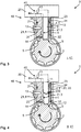
- FIG. 5 and 6 the rest position I and the evasive position II in a schematic representation of the locking device 10. If a transverse force acts along a loading direction 201 on the locking element 11, the locking element 11 presses against the evasion element 22. The evasion element 22 then performs a pivoting movement in the direction of the free space 4.1, so that the free space 4.1 is bridged by the evasive element 22. The evasive element 22 abuts the component housing 4 via the free space 4.1. As a result, the blocking element 11 in the evasive position II of the evasive element 22 can be supported by the evasive element 22 via the free space 4.1 on the component housing 4.
- the evasive element 22 can preferably have a hinge section 24, with which the evasive element 22 is pivotably mounted on the rigid housing section 23.
- the evasive element 22 can be loosely arranged on the rigid housing section 23 during assembly.
- an elastic restoring means 33 for restoring 104 the evasive element 22 from the evasive position II to the rest position I is arranged on the assembly housing 20. By means of the restoring means 33, the evasive element 22 can therefore be moved from the evasive position II into the rest position I, in particular automatically.
- the resetting means 33 effects a resetting force 210 on the evasive element 22 in order to initiate an automatic resetting of the evasive element 22 from the evasive position II to the rest position I.
- a holding element 30 is provided, with which the restoring means 33 is designed in one piece.
- the restoring means 33 forms an elastic section of the holding element 30.
- the rigid housing section 23 and the evasive element 22 also have a recess 26 through which the holding element 30 is fastened to the mounting housing 23 in a form-fitting manner.
- the recess 26 can in particular be designed like a channel so that a form fit is effected in two directions, in particular in the direction of movement 204 of the locking element 11 when adjusting between the locking position and the unlocking position 41, 42.
- Figure 7 shows a top view of the holding element 30 and the locking element guide 21 during the assembly of the holding element 30.
- the evasive element 22 is secured by the holding element 30 in a fastening direction 203 on the rigid housing section 23.
- the recess 26 has an elongated extension in an assembly direction 202 of the holding element 30 with a free assembly outlet 32 which is arranged on an assembly side 21.2 of the locking element guide 21. Due to the free assembly outlet 32, the holding element 30 can be plugged onto the locking element guide 21 in a simple manner, so that the holding element 30 can be guided through the recess 26 along the assembly direction 202 in the recess 26.
- the holding element 30 has a clamping section 31 for fixing the holding element 30 on the mounting housing 20, in particular in a mounting direction 202 of the holding element 30.
- the evasive element 22 can be fixed to the rigid housing section 23 in a form-fitting and / or force-fitting manner.
- the holding element 30 engages around the locking element guide 21 in the assembled state in a clamp-like manner.
- the holding element 30 has at least one flexible and / or elastic section, which according to the illustration in FIG Figure 6 is elastically adjustable during the pivoting movement of the evasive element 22. This gives the evasive element 22 a possibility of movement in the loading direction 201 or in the direction of the free space 4.1.
- a locking mechanism 40 for adjusting the locking element 11 between the locking position 41 and the unlocking position 42 has a control cam 44 on which the locking element 11 is guided.
- the adjustment mechanism 40 is preferably in Mounting housing 20 arranged.
- the locking element 11 also has a roll-off means 43, by means of which the locking element 11 can roll on the control cam 44 in order to promote a pivotable mounting of the locking element 11 on the adjusting mechanism 40.
- the locking element 11 can even be given the freedom of movement for the tilting movement 200 by the adjustment mechanism 40.
- damage to the assembly housing 20 due to a load in the direction of the free space 4.1 is avoided or reduced.
- Figure 8 shows a locking element guide 21 of a locking device 10 according to the invention in a top view during the assembly of the retaining element 30.
- the evasive element 22 extends over at least two sides of the locking element guide 21, whereby the evasive element has an extension in at least two spatial directions that is greater than a diameter an access opening 5 through which the locking element 11 for locking the functionally essential component 2 can be pushed.
- the evasive element 22 cannot fall through the access opening 5 in the direction of the functionally essential component 2 and damage it or block its function.
- Figure 9 shows a vehicle 1 with a functional unit 3 according to the invention in the form of a steering gear.
- a functionally essential component 2 is formed by a steering column of the vehicle 1.
- the functional unit 3 is preferably designed in accordance with one of the exemplary embodiments described above. As a result, the security of the vehicle 1 can be increased overall if an unauthorized actuation of the functionally essential component 2 does not damage a locking device 10 of the functional unit 3.
Landscapes
- Engineering & Computer Science (AREA)
- Mechanical Engineering (AREA)
- Lock And Its Accessories (AREA)
Applications Claiming Priority (1)
| Application Number | Priority Date | Filing Date | Title |
|---|---|---|---|
| DE102019125189.3A DE102019125189A1 (de) | 2019-09-19 | 2019-09-19 | Verriegelungsvorrichtung für ein funktionswesentliches Bauteil, Funktionseinheit für ein Fahrzeug sowie Verfahren zum zerstörungsfreien Abstützen einer Bewegung eines funktionswesentlichen Bauteils |
Publications (2)
| Publication Number | Publication Date |
|---|---|
| EP3795431A1 true EP3795431A1 (fr) | 2021-03-24 |
| EP3795431B1 EP3795431B1 (fr) | 2023-11-29 |
Family
ID=72470160
Family Applications (1)
| Application Number | Title | Priority Date | Filing Date |
|---|---|---|---|
| EP20195281.9A Active EP3795431B1 (fr) | 2019-09-19 | 2020-09-09 | Dispositif de verrouillage pour un composant fonctionnel, unité fonctionnelle pour un véhicule ainsi que procédé de support non destructif pour un mouvement d'un composant fonctionnel |
Country Status (3)
| Country | Link |
|---|---|
| EP (1) | EP3795431B1 (fr) |
| CN (1) | CN112519718B (fr) |
| DE (1) | DE102019125189A1 (fr) |
Citations (3)
| Publication number | Priority date | Publication date | Assignee | Title |
|---|---|---|---|---|
| EP0887240A2 (fr) * | 1997-05-07 | 1998-12-30 | VALEO GmbH & Co Schliesssysteme KG | Dispositif de verrouillage pour véhicule automobile |
| EP1249375A2 (fr) * | 2001-04-14 | 2002-10-16 | Huf Hülsbeck & Fürst GmbH & Co. KG | Dispositif de verrouillage pour la colonne de direction d'un véhicule |
| US20040069026A1 (en) * | 2002-10-04 | 2004-04-15 | Keisuke Fukushima | Electrically-operated steering lock device |
Family Cites Families (13)
| Publication number | Priority date | Publication date | Assignee | Title |
|---|---|---|---|---|
| DE10017032B4 (de) * | 2000-04-05 | 2008-04-17 | Valeo Deutschland Gmbh & Co. Sicherheitssysteme | Vorrichtung zur Ver- und Entriegelung der Lenkspindel einer Lenkeinrichtung |
| DE102004043898B3 (de) * | 2004-09-10 | 2005-12-01 | Huf Hülsbeck & Fürst Gmbh & Co. Kg | Vorrichtung zum Sperren der Lenkspindel eines Kraftfahrzeugs |
| ATE454295T1 (de) * | 2006-04-13 | 2010-01-15 | Huf Huelsbeck & Fuerst Gmbh | Verriegelungsvorrichtung |
| JP4819729B2 (ja) * | 2007-03-27 | 2011-11-24 | 株式会社ユーシン | ステアリングロック装置 |
| DE102007018218A1 (de) * | 2007-04-16 | 2008-10-23 | Huf Hülsbeck & Fürst Gmbh & Co. Kg | Vorrichtung zur Ansteuerung eines Sperrgliedes |
| DE102007034481A1 (de) * | 2007-07-20 | 2009-01-22 | Huf Hülsbeck & Fürst Gmbh & Co. Kg | Verriegelungsvorrichtung mit Arretierungsteil |
| DE102008013487A1 (de) * | 2008-03-10 | 2009-09-17 | Huf Hülsbeck & Fürst Gmbh & Co. Kg | Verfahren sowie Vorrichtung zur Ansteuerung eines Sperrgliedes |
| DE102008023997B4 (de) * | 2008-05-16 | 2019-04-25 | Huf Hülsbeck & Fürst GmbH & Co KG | Sperrvorrichtung mit einem Sperrglied zur Sperrung eines funktionswesentlichen Bauteils |
| DE102010037071A1 (de) * | 2010-08-19 | 2012-02-23 | Huf Hülsbeck & Fürst Gmbh & Co. Kg | Vorrichtung zur Verlagerung eines bewegbaren Sperrelementes |
| EP2476593B1 (fr) * | 2011-01-13 | 2014-01-08 | Valeo Sicherheitssysteme GmbH | Procédé de protection contre le vol d'un vehicule automobile |
| DE102013018835A1 (de) * | 2013-09-19 | 2015-03-19 | Huf Hülsbeck & Fürst Gmbh & Co. Kg | Mechanische Lenkungsverriegelung für Fahrzeuge |
| DE102014112816A1 (de) * | 2014-09-05 | 2016-03-10 | Huf Hülsbeck & Fürst Gmbh & Co. Kg | Lenkradverriegelung |
| DE102014017828A1 (de) * | 2014-12-03 | 2015-06-18 | Daimler Ag | Lenkungsverriegelungsvorrichtung für ein Fahrzeug |
-
2019
- 2019-09-19 DE DE102019125189.3A patent/DE102019125189A1/de active Pending
-
2020
- 2020-09-09 EP EP20195281.9A patent/EP3795431B1/fr active Active
- 2020-09-15 CN CN202010966025.2A patent/CN112519718B/zh active Active
Patent Citations (3)
| Publication number | Priority date | Publication date | Assignee | Title |
|---|---|---|---|---|
| EP0887240A2 (fr) * | 1997-05-07 | 1998-12-30 | VALEO GmbH & Co Schliesssysteme KG | Dispositif de verrouillage pour véhicule automobile |
| EP1249375A2 (fr) * | 2001-04-14 | 2002-10-16 | Huf Hülsbeck & Fürst GmbH & Co. KG | Dispositif de verrouillage pour la colonne de direction d'un véhicule |
| US20040069026A1 (en) * | 2002-10-04 | 2004-04-15 | Keisuke Fukushima | Electrically-operated steering lock device |
Also Published As
| Publication number | Publication date |
|---|---|
| CN112519718A (zh) | 2021-03-19 |
| DE102019125189A1 (de) | 2021-03-25 |
| EP3795431B1 (fr) | 2023-11-29 |
| DE102019125189A9 (de) | 2021-07-01 |
| CN112519718B (zh) | 2023-12-12 |
Similar Documents
| Publication | Publication Date | Title |
|---|---|---|
| EP3020902B1 (fr) | Chariot à bobines pour la réception d'une porte coulissante dotée d'un dispositif anti-levage | |
| DE3781390T2 (de) | Selbstblockierende sicherheitsseilklemme. | |
| DE102012006060B4 (de) | Entriegelungsvorrichtung für das Verriegelungsmittel einer Sitzschiene | |
| EP3020901B1 (fr) | Chariot à bobines pour la réception d'une porte coulissante dotée d'au moins deux dispositifs de montage | |
| DE102009038317B4 (de) | Verstellbare Lenksäule für ein Kraftfahrzeug | |
| EP3577011B1 (fr) | Colonne de direction pour un véhicule automobile | |
| EP4234864B1 (fr) | Arrêt de porte | |
| WO2012079096A1 (fr) | Colonne de direction pour un véhicule automobile | |
| DE102006004678A1 (de) | Montageeinheit für die Befestigungsöse eines Gurtschlosses | |
| WO2016193011A1 (fr) | Système de verrouillage pour un connecteur de charge | |
| DE10260368A1 (de) | Verbesserte Diebstahlschutzvorrichtung für ein Fahrzeug | |
| EP1839915A2 (fr) | Dispositif de serrage pour une chaîne antidérapante | |
| EP3911553B1 (fr) | Colonne de direction pour un véhicule automobile | |
| EP1277611A1 (fr) | Charnière extérieure pour la fixation d'un dossier | |
| EP2993090B1 (fr) | Verrouillage de volant de direction | |
| DE10335311A1 (de) | Lenkschlossvorrichtung | |
| EP2789779B1 (fr) | Dispositif de fixation pour une porte coulissante d'un véhicule automobile | |
| EP3795431B1 (fr) | Dispositif de verrouillage pour un composant fonctionnel, unité fonctionnelle pour un véhicule ainsi que procédé de support non destructif pour un mouvement d'un composant fonctionnel | |
| EP2288417B1 (fr) | Appareil de blocage entraîné | |
| WO2018215842A1 (fr) | Fixation de câble et élément de passage formant coulisse | |
| EP3428374B1 (fr) | Dispositif articulé à résistance au pivotement dépendante de la direction | |
| DE202018101859U1 (de) | Vorrichtung zum Fixieren eines Batterietrogs eines Flurförderzeugs | |
| EP3347626B1 (fr) | Dispositif de frein de stationnement pour une boîte de vitesses de véhicule automobile | |
| DE102013220567B4 (de) | Lenkradschloss, Lenksäule und Lenksystem | |
| DE3148972A1 (de) | Schnapp- und sperrmechanismus fuer ein kraftfahrzeug zum zuhalten eines aufstellbaren teiles, insbesondere einer motorhaube oder eines kofferraumdeckels |
Legal Events
| Date | Code | Title | Description |
|---|---|---|---|
| PUAI | Public reference made under article 153(3) epc to a published international application that has entered the european phase |
Free format text: ORIGINAL CODE: 0009012 |
|
| STAA | Information on the status of an ep patent application or granted ep patent |
Free format text: STATUS: THE APPLICATION HAS BEEN PUBLISHED |
|
| AK | Designated contracting states |
Kind code of ref document: A1 Designated state(s): AL AT BE BG CH CY CZ DE DK EE ES FI FR GB GR HR HU IE IS IT LI LT LU LV MC MK MT NL NO PL PT RO RS SE SI SK SM TR |
|
| AX | Request for extension of the european patent |
Extension state: BA ME |
|
| STAA | Information on the status of an ep patent application or granted ep patent |
Free format text: STATUS: REQUEST FOR EXAMINATION WAS MADE |
|
| 17P | Request for examination filed |
Effective date: 20210924 |
|
| RBV | Designated contracting states (corrected) |
Designated state(s): AL AT BE BG CH CY CZ DE DK EE ES FI FR GB GR HR HU IE IS IT LI LT LU LV MC MK MT NL NO PL PT RO RS SE SI SK SM TR |
|
| GRAP | Despatch of communication of intention to grant a patent |
Free format text: ORIGINAL CODE: EPIDOSNIGR1 |
|
| STAA | Information on the status of an ep patent application or granted ep patent |
Free format text: STATUS: GRANT OF PATENT IS INTENDED |
|
| INTG | Intention to grant announced |
Effective date: 20230609 |
|
| P01 | Opt-out of the competence of the unified patent court (upc) registered |
Effective date: 20230711 |
|
| GRAS | Grant fee paid |
Free format text: ORIGINAL CODE: EPIDOSNIGR3 |
|
| GRAA | (expected) grant |
Free format text: ORIGINAL CODE: 0009210 |
|
| STAA | Information on the status of an ep patent application or granted ep patent |
Free format text: STATUS: THE PATENT HAS BEEN GRANTED |
|
| AK | Designated contracting states |
Kind code of ref document: B1 Designated state(s): AL AT BE BG CH CY CZ DE DK EE ES FI FR GB GR HR HU IE IS IT LI LT LU LV MC MK MT NL NO PL PT RO RS SE SI SK SM TR |
|
| REG | Reference to a national code |
Ref country code: GB Ref legal event code: FG4D Free format text: NOT ENGLISH |
|
| REG | Reference to a national code |
Ref country code: CH Ref legal event code: EP |
|
| REG | Reference to a national code |
Ref country code: DE Ref legal event code: R096 Ref document number: 502020006178 Country of ref document: DE |
|
| REG | Reference to a national code |
Ref country code: IE Ref legal event code: FG4D Free format text: LANGUAGE OF EP DOCUMENT: GERMAN |
|
| REG | Reference to a national code |
Ref country code: DE Ref legal event code: R084 Ref document number: 502020006178 Country of ref document: DE |
|
| REG | Reference to a national code |
Ref country code: LT Ref legal event code: MG9D |
|
| REG | Reference to a national code |
Ref country code: NL Ref legal event code: MP Effective date: 20231129 |
|
| PG25 | Lapsed in a contracting state [announced via postgrant information from national office to epo] |
Ref country code: GR Free format text: LAPSE BECAUSE OF FAILURE TO SUBMIT A TRANSLATION OF THE DESCRIPTION OR TO PAY THE FEE WITHIN THE PRESCRIBED TIME-LIMIT Effective date: 20240301 |
|
| PG25 | Lapsed in a contracting state [announced via postgrant information from national office to epo] |
Ref country code: IS Free format text: LAPSE BECAUSE OF FAILURE TO SUBMIT A TRANSLATION OF THE DESCRIPTION OR TO PAY THE FEE WITHIN THE PRESCRIBED TIME-LIMIT Effective date: 20240329 |
|
| PG25 | Lapsed in a contracting state [announced via postgrant information from national office to epo] |
Ref country code: LT Free format text: LAPSE BECAUSE OF FAILURE TO SUBMIT A TRANSLATION OF THE DESCRIPTION OR TO PAY THE FEE WITHIN THE PRESCRIBED TIME-LIMIT Effective date: 20231129 |
|
| PG25 | Lapsed in a contracting state [announced via postgrant information from national office to epo] |
Ref country code: ES Free format text: LAPSE BECAUSE OF FAILURE TO SUBMIT A TRANSLATION OF THE DESCRIPTION OR TO PAY THE FEE WITHIN THE PRESCRIBED TIME-LIMIT Effective date: 20231129 |
|
| PG25 | Lapsed in a contracting state [announced via postgrant information from national office to epo] |
Ref country code: LT Free format text: LAPSE BECAUSE OF FAILURE TO SUBMIT A TRANSLATION OF THE DESCRIPTION OR TO PAY THE FEE WITHIN THE PRESCRIBED TIME-LIMIT Effective date: 20231129 Ref country code: IS Free format text: LAPSE BECAUSE OF FAILURE TO SUBMIT A TRANSLATION OF THE DESCRIPTION OR TO PAY THE FEE WITHIN THE PRESCRIBED TIME-LIMIT Effective date: 20240329 Ref country code: GR Free format text: LAPSE BECAUSE OF FAILURE TO SUBMIT A TRANSLATION OF THE DESCRIPTION OR TO PAY THE FEE WITHIN THE PRESCRIBED TIME-LIMIT Effective date: 20240301 Ref country code: ES Free format text: LAPSE BECAUSE OF FAILURE TO SUBMIT A TRANSLATION OF THE DESCRIPTION OR TO PAY THE FEE WITHIN THE PRESCRIBED TIME-LIMIT Effective date: 20231129 Ref country code: BG Free format text: LAPSE BECAUSE OF FAILURE TO SUBMIT A TRANSLATION OF THE DESCRIPTION OR TO PAY THE FEE WITHIN THE PRESCRIBED TIME-LIMIT Effective date: 20240229 |
|
| PG25 | Lapsed in a contracting state [announced via postgrant information from national office to epo] |
Ref country code: NL Free format text: LAPSE BECAUSE OF FAILURE TO SUBMIT A TRANSLATION OF THE DESCRIPTION OR TO PAY THE FEE WITHIN THE PRESCRIBED TIME-LIMIT Effective date: 20231129 |
|
| PG25 | Lapsed in a contracting state [announced via postgrant information from national office to epo] |
Ref country code: SE Free format text: LAPSE BECAUSE OF FAILURE TO SUBMIT A TRANSLATION OF THE DESCRIPTION OR TO PAY THE FEE WITHIN THE PRESCRIBED TIME-LIMIT Effective date: 20231129 Ref country code: RS Free format text: LAPSE BECAUSE OF FAILURE TO SUBMIT A TRANSLATION OF THE DESCRIPTION OR TO PAY THE FEE WITHIN THE PRESCRIBED TIME-LIMIT Effective date: 20231129 Ref country code: PL Free format text: LAPSE BECAUSE OF FAILURE TO SUBMIT A TRANSLATION OF THE DESCRIPTION OR TO PAY THE FEE WITHIN THE PRESCRIBED TIME-LIMIT Effective date: 20231129 Ref country code: NO Free format text: LAPSE BECAUSE OF FAILURE TO SUBMIT A TRANSLATION OF THE DESCRIPTION OR TO PAY THE FEE WITHIN THE PRESCRIBED TIME-LIMIT Effective date: 20240229 Ref country code: NL Free format text: LAPSE BECAUSE OF FAILURE TO SUBMIT A TRANSLATION OF THE DESCRIPTION OR TO PAY THE FEE WITHIN THE PRESCRIBED TIME-LIMIT Effective date: 20231129 Ref country code: LV Free format text: LAPSE BECAUSE OF FAILURE TO SUBMIT A TRANSLATION OF THE DESCRIPTION OR TO PAY THE FEE WITHIN THE PRESCRIBED TIME-LIMIT Effective date: 20231129 Ref country code: HR Free format text: LAPSE BECAUSE OF FAILURE TO SUBMIT A TRANSLATION OF THE DESCRIPTION OR TO PAY THE FEE WITHIN THE PRESCRIBED TIME-LIMIT Effective date: 20231129 |
|
| PG25 | Lapsed in a contracting state [announced via postgrant information from national office to epo] |
Ref country code: DK Free format text: LAPSE BECAUSE OF FAILURE TO SUBMIT A TRANSLATION OF THE DESCRIPTION OR TO PAY THE FEE WITHIN THE PRESCRIBED TIME-LIMIT Effective date: 20231129 |
|
| PG25 | Lapsed in a contracting state [announced via postgrant information from national office to epo] |
Ref country code: CZ Free format text: LAPSE BECAUSE OF FAILURE TO SUBMIT A TRANSLATION OF THE DESCRIPTION OR TO PAY THE FEE WITHIN THE PRESCRIBED TIME-LIMIT Effective date: 20231129 |
|
| PG25 | Lapsed in a contracting state [announced via postgrant information from national office to epo] |
Ref country code: SK Free format text: LAPSE BECAUSE OF FAILURE TO SUBMIT A TRANSLATION OF THE DESCRIPTION OR TO PAY THE FEE WITHIN THE PRESCRIBED TIME-LIMIT Effective date: 20231129 |
|
| PG25 | Lapsed in a contracting state [announced via postgrant information from national office to epo] |
Ref country code: SM Free format text: LAPSE BECAUSE OF FAILURE TO SUBMIT A TRANSLATION OF THE DESCRIPTION OR TO PAY THE FEE WITHIN THE PRESCRIBED TIME-LIMIT Effective date: 20231129 Ref country code: SK Free format text: LAPSE BECAUSE OF FAILURE TO SUBMIT A TRANSLATION OF THE DESCRIPTION OR TO PAY THE FEE WITHIN THE PRESCRIBED TIME-LIMIT Effective date: 20231129 Ref country code: RO Free format text: LAPSE BECAUSE OF FAILURE TO SUBMIT A TRANSLATION OF THE DESCRIPTION OR TO PAY THE FEE WITHIN THE PRESCRIBED TIME-LIMIT Effective date: 20231129 Ref country code: IT Free format text: LAPSE BECAUSE OF FAILURE TO SUBMIT A TRANSLATION OF THE DESCRIPTION OR TO PAY THE FEE WITHIN THE PRESCRIBED TIME-LIMIT Effective date: 20231129 Ref country code: EE Free format text: LAPSE BECAUSE OF FAILURE TO SUBMIT A TRANSLATION OF THE DESCRIPTION OR TO PAY THE FEE WITHIN THE PRESCRIBED TIME-LIMIT Effective date: 20231129 Ref country code: DK Free format text: LAPSE BECAUSE OF FAILURE TO SUBMIT A TRANSLATION OF THE DESCRIPTION OR TO PAY THE FEE WITHIN THE PRESCRIBED TIME-LIMIT Effective date: 20231129 Ref country code: CZ Free format text: LAPSE BECAUSE OF FAILURE TO SUBMIT A TRANSLATION OF THE DESCRIPTION OR TO PAY THE FEE WITHIN THE PRESCRIBED TIME-LIMIT Effective date: 20231129 |
|
| PG25 | Lapsed in a contracting state [announced via postgrant information from national office to epo] |
Ref country code: PT Free format text: LAPSE BECAUSE OF FAILURE TO SUBMIT A TRANSLATION OF THE DESCRIPTION OR TO PAY THE FEE WITHIN THE PRESCRIBED TIME-LIMIT Effective date: 20240401 |
|
| PG25 | Lapsed in a contracting state [announced via postgrant information from national office to epo] |
Ref country code: PT Free format text: LAPSE BECAUSE OF FAILURE TO SUBMIT A TRANSLATION OF THE DESCRIPTION OR TO PAY THE FEE WITHIN THE PRESCRIBED TIME-LIMIT Effective date: 20240401 |
|
| REG | Reference to a national code |
Ref country code: DE Ref legal event code: R097 Ref document number: 502020006178 Country of ref document: DE |
|
| PLBE | No opposition filed within time limit |
Free format text: ORIGINAL CODE: 0009261 |
|
| STAA | Information on the status of an ep patent application or granted ep patent |
Free format text: STATUS: NO OPPOSITION FILED WITHIN TIME LIMIT |
|
| PG25 | Lapsed in a contracting state [announced via postgrant information from national office to epo] |
Ref country code: SI Free format text: LAPSE BECAUSE OF FAILURE TO SUBMIT A TRANSLATION OF THE DESCRIPTION OR TO PAY THE FEE WITHIN THE PRESCRIBED TIME-LIMIT Effective date: 20231129 |
|
| PG25 | Lapsed in a contracting state [announced via postgrant information from national office to epo] |
Ref country code: SI Free format text: LAPSE BECAUSE OF FAILURE TO SUBMIT A TRANSLATION OF THE DESCRIPTION OR TO PAY THE FEE WITHIN THE PRESCRIBED TIME-LIMIT Effective date: 20231129 |
|
| 26N | No opposition filed |
Effective date: 20240830 |
|
| PG25 | Lapsed in a contracting state [announced via postgrant information from national office to epo] |
Ref country code: MC Free format text: LAPSE BECAUSE OF FAILURE TO SUBMIT A TRANSLATION OF THE DESCRIPTION OR TO PAY THE FEE WITHIN THE PRESCRIBED TIME-LIMIT Effective date: 20231129 |
|
| REG | Reference to a national code |
Ref country code: CH Ref legal event code: PL |
|
| PG25 | Lapsed in a contracting state [announced via postgrant information from national office to epo] |
Ref country code: LU Free format text: LAPSE BECAUSE OF NON-PAYMENT OF DUE FEES Effective date: 20240909 |
|
| GBPC | Gb: european patent ceased through non-payment of renewal fee |
Effective date: 20240909 |
|
| PG25 | Lapsed in a contracting state [announced via postgrant information from national office to epo] |
Ref country code: GB Free format text: LAPSE BECAUSE OF NON-PAYMENT OF DUE FEES Effective date: 20240909 |
|
| REG | Reference to a national code |
Ref country code: BE Ref legal event code: MM Effective date: 20240930 |
|
| PG25 | Lapsed in a contracting state [announced via postgrant information from national office to epo] |
Ref country code: BE Free format text: LAPSE BECAUSE OF NON-PAYMENT OF DUE FEES Effective date: 20240930 |
|
| PG25 | Lapsed in a contracting state [announced via postgrant information from national office to epo] |
Ref country code: FR Free format text: LAPSE BECAUSE OF NON-PAYMENT OF DUE FEES Effective date: 20240930 |
|
| PG25 | Lapsed in a contracting state [announced via postgrant information from national office to epo] |
Ref country code: CH Free format text: LAPSE BECAUSE OF NON-PAYMENT OF DUE FEES Effective date: 20240930 |
|
| PG25 | Lapsed in a contracting state [announced via postgrant information from national office to epo] |
Ref country code: IE Free format text: LAPSE BECAUSE OF NON-PAYMENT OF DUE FEES Effective date: 20240909 |
|
| PG25 | Lapsed in a contracting state [announced via postgrant information from national office to epo] |
Ref country code: FI Free format text: LAPSE BECAUSE OF FAILURE TO SUBMIT A TRANSLATION OF THE DESCRIPTION OR TO PAY THE FEE WITHIN THE PRESCRIBED TIME-LIMIT Effective date: 20231129 |
|
| PGFP | Annual fee paid to national office [announced via postgrant information from national office to epo] |
Ref country code: DE Payment date: 20250930 Year of fee payment: 6 |
|
| PGFP | Annual fee paid to national office [announced via postgrant information from national office to epo] |
Ref country code: AT Payment date: 20251020 Year of fee payment: 5 |
|
| PG25 | Lapsed in a contracting state [announced via postgrant information from national office to epo] |
Ref country code: CY Free format text: LAPSE BECAUSE OF FAILURE TO SUBMIT A TRANSLATION OF THE DESCRIPTION OR TO PAY THE FEE WITHIN THE PRESCRIBED TIME-LIMIT; INVALID AB INITIO Effective date: 20200909 |
|
| PG25 | Lapsed in a contracting state [announced via postgrant information from national office to epo] |
Ref country code: HU Free format text: LAPSE BECAUSE OF FAILURE TO SUBMIT A TRANSLATION OF THE DESCRIPTION OR TO PAY THE FEE WITHIN THE PRESCRIBED TIME-LIMIT; INVALID AB INITIO Effective date: 20200909 |