EP3795862A1 - Elektrisch isoliertes durchführungsrohr - Google Patents
Elektrisch isoliertes durchführungsrohr Download PDFInfo
- Publication number
- EP3795862A1 EP3795862A1 EP19198725.4A EP19198725A EP3795862A1 EP 3795862 A1 EP3795862 A1 EP 3795862A1 EP 19198725 A EP19198725 A EP 19198725A EP 3795862 A1 EP3795862 A1 EP 3795862A1
- Authority
- EP
- European Patent Office
- Prior art keywords
- tube
- fixing means
- lead
- transmission
- arrangement according
- Prior art date
- Legal status (The legal status is an assumption and is not a legal conclusion. Google has not performed a legal analysis and makes no representation as to the accuracy of the status listed.)
- Granted
Links
Images
Classifications
-
- F—MECHANICAL ENGINEERING; LIGHTING; HEATING; WEAPONS; BLASTING
- F03—MACHINES OR ENGINES FOR LIQUIDS; WIND, SPRING, OR WEIGHT MOTORS; PRODUCING MECHANICAL POWER OR A REACTIVE PROPULSIVE THRUST, NOT OTHERWISE PROVIDED FOR
- F03D—WIND MOTORS
- F03D15/00—Transmission of mechanical power
-
- F—MECHANICAL ENGINEERING; LIGHTING; HEATING; WEAPONS; BLASTING
- F16—ENGINEERING ELEMENTS AND UNITS; GENERAL MEASURES FOR PRODUCING AND MAINTAINING EFFECTIVE FUNCTIONING OF MACHINES OR INSTALLATIONS; THERMAL INSULATION IN GENERAL
- F16H—GEARING
- F16H15/00—Gearings for conveying rotary motion with variable gear ratio, or for reversing rotary motion, by friction between rotary members
- F16H15/48—Gearings for conveying rotary motion with variable gear ratio, or for reversing rotary motion, by friction between rotary members with members having orbital motion
- F16H15/50—Gearings providing a continuous range of gear ratios
- F16H15/52—Gearings providing a continuous range of gear ratios in which a member of uniform effective diameter mounted on a shaft may co-operate with different parts of another member
-
- F—MECHANICAL ENGINEERING; LIGHTING; HEATING; WEAPONS; BLASTING
- F16—ENGINEERING ELEMENTS AND UNITS; GENERAL MEASURES FOR PRODUCING AND MAINTAINING EFFECTIVE FUNCTIONING OF MACHINES OR INSTALLATIONS; THERMAL INSULATION IN GENERAL
- F16H—GEARING
- F16H57/00—General details of gearing
- F16H57/02—Gearboxes; Mounting gearing therein
- F16H57/029—Gearboxes; Mounting gearing therein characterised by means for sealing the gearboxes, e.g. to improve airtightness
-
- F—MECHANICAL ENGINEERING; LIGHTING; HEATING; WEAPONS; BLASTING
- F16—ENGINEERING ELEMENTS AND UNITS; GENERAL MEASURES FOR PRODUCING AND MAINTAINING EFFECTIVE FUNCTIONING OF MACHINES OR INSTALLATIONS; THERMAL INSULATION IN GENERAL
- F16H—GEARING
- F16H57/00—General details of gearing
- F16H57/08—General details of gearing of gearings with members having orbital motion
-
- H—ELECTRICITY
- H01—ELECTRIC ELEMENTS
- H01B—CABLES; CONDUCTORS; INSULATORS; SELECTION OF MATERIALS FOR THEIR CONDUCTIVE, INSULATING OR DIELECTRIC PROPERTIES
- H01B17/00—Insulators or insulating bodies characterised by their form
- H01B17/56—Insulating bodies
- H01B17/58—Tubes, sleeves, beads, or bobbins through which the conductor passes
- H01B17/583—Grommets; Bushings
-
- H—ELECTRICITY
- H02—GENERATION; CONVERSION OR DISTRIBUTION OF ELECTRIC POWER
- H02G—INSTALLATION OF ELECTRIC CABLES OR LINES, OR OF COMBINED OPTICAL AND ELECTRIC CABLES OR LINES
- H02G3/00—Installations of electric cables or lines or protective tubing therefor in or on buildings, equivalent structures or vehicles
- H02G3/02—Details
- H02G3/04—Protective tubing or conduits, e.g. cable ladders or cable troughs
- H02G3/0406—Details thereof
-
- H—ELECTRICITY
- H02—GENERATION; CONVERSION OR DISTRIBUTION OF ELECTRIC POWER
- H02G—INSTALLATION OF ELECTRIC CABLES OR LINES, OR OF COMBINED OPTICAL AND ELECTRIC CABLES OR LINES
- H02G3/00—Installations of electric cables or lines or protective tubing therefor in or on buildings, equivalent structures or vehicles
- H02G3/02—Details
- H02G3/04—Protective tubing or conduits, e.g. cable ladders or cable troughs
- H02G3/0462—Tubings, i.e. having a closed section
-
- F—MECHANICAL ENGINEERING; LIGHTING; HEATING; WEAPONS; BLASTING
- F03—MACHINES OR ENGINES FOR LIQUIDS; WIND, SPRING, OR WEIGHT MOTORS; PRODUCING MECHANICAL POWER OR A REACTIVE PROPULSIVE THRUST, NOT OTHERWISE PROVIDED FOR
- F03D—WIND MOTORS
- F03D80/00—Details, components or accessories not provided for in groups F03D1/00 - F03D17/00
- F03D80/80—Arrangement of components within nacelles or towers
- F03D80/82—Arrangement of components within nacelles or towers of electrical components
- F03D80/85—Cabling
-
- F—MECHANICAL ENGINEERING; LIGHTING; HEATING; WEAPONS; BLASTING
- F05—INDEXING SCHEMES RELATING TO ENGINES OR PUMPS IN VARIOUS SUBCLASSES OF CLASSES F01-F04
- F05B—INDEXING SCHEME RELATING TO WIND, SPRING, WEIGHT, INERTIA OR LIKE MOTORS, TO MACHINES OR ENGINES FOR LIQUIDS COVERED BY SUBCLASSES F03B, F03D AND F03G
- F05B2260/00—Function
- F05B2260/40—Transmission of power
-
- F—MECHANICAL ENGINEERING; LIGHTING; HEATING; WEAPONS; BLASTING
- F16—ENGINEERING ELEMENTS AND UNITS; GENERAL MEASURES FOR PRODUCING AND MAINTAINING EFFECTIVE FUNCTIONING OF MACHINES OR INSTALLATIONS; THERMAL INSULATION IN GENERAL
- F16H—GEARING
- F16H57/00—General details of gearing
- F16H57/02—Gearboxes; Mounting gearing therein
- F16H2057/02039—Gearboxes for particular applications
- F16H2057/02078—Gearboxes for particular applications for wind turbines
-
- Y—GENERAL TAGGING OF NEW TECHNOLOGICAL DEVELOPMENTS; GENERAL TAGGING OF CROSS-SECTIONAL TECHNOLOGIES SPANNING OVER SEVERAL SECTIONS OF THE IPC; TECHNICAL SUBJECTS COVERED BY FORMER USPC CROSS-REFERENCE ART COLLECTIONS [XRACs] AND DIGESTS
- Y02—TECHNOLOGIES OR APPLICATIONS FOR MITIGATION OR ADAPTATION AGAINST CLIMATE CHANGE
- Y02E—REDUCTION OF GREENHOUSE GAS [GHG] EMISSIONS, RELATED TO ENERGY GENERATION, TRANSMISSION OR DISTRIBUTION
- Y02E10/00—Energy generation through renewable energy sources
- Y02E10/70—Wind energy
- Y02E10/72—Wind turbines with rotation axis in wind direction
Definitions
- the invention is based on the object of making available an improved solution compared to the gearboxes known from the prior art. In particular, damage that can occur in an integrated drive train due to stray currents should be avoided.
- the transmission can in particular be a transmission for a wind turbine.
- a feed-through pipe also known as a pitch tube, is a pipe for passing electrical or hydraulic supply lines through the transmission. It is characterized in that it passes through the gear or the housing of the gear and its mouths are arranged outside the gear or the housing of the gear.
- the lead-through tube is preferably sealed so that it is impermeable to lubricants with respect to the housing of the transmission.
- the lead-through tube is fixed in the transmission, that is to say in at least one component of the transmission, by means of the fixing means.
- the lead-through tube is usually designed to be rotationally symmetrical. Accordingly, the fixing means is preferably also rotationally symmetrical.
- the invention is based on the knowledge that the lead-through pipe is a significant transmitter of stray currents due to the fact that it extends completely through the transmission.
- the fixing means is therefore designed to be electrically insulating with respect to the lead-through tube.
- the fixing means thus electrically isolates the lead-through tube and the component of the transmission, in which the lead-through tube is fixed by means of the fixing means, from one another. This eliminates a major cause of leakage currents.
- the invention effectively prevents leakage currents emanating from a generator from being introduced into the transmission via the lead-through pipe.
- the insulation according to the invention is particularly suitable for integrated drive trains, since it takes up little space.
- the leadthrough tube is designed to be axially movable relative to the fixing means, ie in the direction of an axis of rotation, for example an axis of rotation of the component in which the leadthrough tube is fixed by means of the fixing means. This allows Compensate for changes in length of the duct due to temperature fluctuations.
- the component of the transmission in which the lead-through tube is fixed by means of the fixing means is a shaft, in particular a hollow shaft, or a rotatably mounted planet carrier.
- the fixing means electrically isolates the lead-through tube from the shaft or the planet carrier.
- the fixing means has a through hole.
- the hole is aligned centrally, that is, its central axis coincides with a central axis of the duct.
- the lead-through tube and the hole can be rotationally symmetrical. In this case, an axis of symmetry of the duct and an axis of symmetry of the hole coincide.
- the lead-through tube runs through the hole and is there with the fixing agent.
- the fixing means is joined along its radially outer edge to the component of the transmission in which the leadthrough tube is fixed, or to the shaft or the planet carrier.
- the fixing means has an electrical non-conductor and a base body.
- the latter can consist of an electrically conductive material.
- the electrical non-conductor is arranged between the lead-through tube and the base body or, according to a further development, between the base body and the component of the transmission in which the lead-through pipe is fixed by means of the fixing means, or between the base body and the shaft or the planet carrier.
- the base body is preferably developed in such a way that at least part of the base body is arranged radially between the lead-through tube and the non-conductor.
- This part of the base body is preferably closed in the circumferential direction.
- the part of the base body can be shaped as a hollow cylinder be. Preferably, it completely fills an intermediate space running between the lead-through pipe and the non-conductor.
- a base body whose material has the same coefficient of thermal expansion as the material of the lead-through tube is also preferred.
- the base body and the lead-through tube can consist of the same material.
- the further development is advantageous when the non-conductor and the lead-through tube have different coefficients of thermal expansion. Then there would be the risk that different dimensional changes as a result of temperature fluctuations impair the axial mobility of the lead-through tube in the fixing means.
- the part of the fixing means according to the further development shields the lead-through tube against dimensional changes in the non-conductor. The axial mobility of the lead-through tube is thus guaranteed.
- the arrangement is preferably developed with a generator which is connected to the transmission in a rotationally effective manner.
- a generator which is connected to the transmission in a rotationally effective manner.
- an output shaft of the transmission is non-rotatably connected to an input shaft of the generator.
- the transmission and the generator can form an integrated drive train.
- a clutch is provided which connects the output shaft of the transmission to the input shaft of the generator in a rotationally fixed manner.
- the coupling has an electrically isolating effect. This ensures complete electrical insulation of the components of the gearbox and the generator that are at risk of voltage.
- the invention makes it possible to use an electrically conductive duct, for example a metallic duct.
- the idea on which the invention is based can alternatively be implemented in that the fixing means does not have an electrically insulating effect, but rather the lead-through tube itself. This can be achieved by means of a lead-through tube that consists of an insulator.
- the fixing means 101 shown serves to fix a feed-through tube 103 on the drive side in a planet carrier 105.
- the radial position of the lead-through tube 103 is fixed by the fixing means 101.
- the fixing means 101 itself is rigidly fixed in the planet carrier 105, that is to say a fixing between the fixing means 101 and the planet carrier 105 does not allow any relative movements between the fixing means 101 and the planet carrier 105.
- a metallic base body 107 of the fixing means 101 has an L-shaped cross section.
- the base body 107 is screwed to the planet carrier 105.
- Corresponding screw connections are designed to be electrically insulating.
- An insulating layer 113 is introduced into a gap running between the base body 107 and the planet carrier 105. This consists of an electrical insulator such as polyamide. The insulating layer 113 electrically insulates the base body 107 and thus the lead-through tube 103 from the planet carrier 105. Like the cross section of the base body 107, the cross section of the insulating layer 113 is also L-shaped.
- the axial leg of the base body 107 which is L-shaped in cross section, runs in the axial direction between the insulating layer 113 and the lead-through pipe 103. This prevents dimensional changes in the insulating layer 113 as a result of temperature fluctuations affect the duct 103. In this way, the axial displaceability of the leadthrough tube 103 relative to the planet carrier 105 is retained even in the event of temperature fluctuations.
- the illustrated clutch 201 connects an output-side sun shaft 203 to an input shaft 205 of a generator.
- the sun shaft 203 forms a first flange 207, the input shaft 205 of the generator a second flange 209.
- the first flange 207 and the second flange 209 are screwed together. In this way, a non-rotatable connection is made between the first flange 207 and the second flange 209.
- first flange 207 and the second flange 209 there is a disk 211, which consists of an electrical insulator.
- the screw connections of the first flange 207 and the second flange 209 are also encapsulated with electrical insulators.
- the sun shaft 203 and the input shaft 205 of the generator are electrically isolated from each other.
- the gearbox is completely isolated from the generator.
- Such a combination is particularly advantageous because it allows the insulation to be arranged completely in the installation space of the transmission. The interfaces of the transmission to the outside are therefore not affected.
Landscapes
- Engineering & Computer Science (AREA)
- General Engineering & Computer Science (AREA)
- Mechanical Engineering (AREA)
- Chemical & Material Sciences (AREA)
- Life Sciences & Earth Sciences (AREA)
- Sustainable Development (AREA)
- Sustainable Energy (AREA)
- Combustion & Propulsion (AREA)
- Civil Engineering (AREA)
- Structural Engineering (AREA)
- Architecture (AREA)
- Connection Of Motors, Electrical Generators, Mechanical Devices, And The Like (AREA)
- General Details Of Gearings (AREA)
Abstract
Description
- Bei Windkraftanlagen ist ein Trend hin zu integrierten Antriebssträngen zu verzeichnen. Bei einem integrierten Antriebsstrang bilden das Getriebe und der Generator eine bauliche Einheit. Dies zieht Probleme mit Streuströmen nach sich. Die Streuströme können in Form von hochfrequenten Wechselströmen oder niederfrequenten Gleich- oder Wechselströmen auftreten. Es besteht die Gefahr, dass an Verzahnungen und Wälzlagern durch Spannungsüberschläge Schäden auftreten.
- Um Folgeschäden aufgrund von Streuströmen zu vermeiden, müssen geeignete Maßnahmen zur Isolierung getroffen werden. Bei mittelschnell laufenden Antriebssträngen sind allerdings die zu übertragenden Drehmomente zwischen Getriebe und Generator vergleichsweise hoch. Gleichzeitig mangelt es aufgrund der integrierten Bauweise des Antriebsstrangs zwischen Getriebe und Generator an verfügbarem Bauraum. Dies erschwert eine ausreichende Dimensionierung der drehmomentübertragenden Bauteile. Dies betrifft insbesondere die elektrische Isolierung der drehmomentübertragenden Bauteile.
- Insbesondere eine elektrische Isolierung des sogenannten Durchführungsrohrs ist problematisch, das sich die Länge Durchführungsrohr bei Temperaturschwankungen in axialer Richtung ändert. Zugleich ändert sich der Durchmesser des Durchführungsrohrs. Aufgrund unterschiedlicher Wärmeausdehnungskoeffizienten des Durchführungsrohrs und der als elektrischer Isolator in Frage kommenden Materialien besteht daher die Gefahr, dass sich das Durchführungsrohr in dem Isolator "verklemmt".
- Der Erfindung liegt die Aufgabe zugrunde, eine gegenüber den aus dem Stand der Technik bekannten Getrieben verbesserte Lösung verfügbar zu machen. Insbesondere sollen Schäden, die in einem integrierten Antriebsstrang aufgrund von Streuströmen auftreten können, vermieden werden.
- Diese Aufgabe wird gelöst durch eine Anordnung nach Anspruch 1. Bevorzugte Weiterbildungen sind in den Unteransprüchen enthalten.
- Bei dem Getriebe kann es sich insbesondere um ein Getriebe für eine Windkraftanlage handeln. Ein Durchführungsrohr, auch Pitch Tube genannt, ist ein Rohr zum Durchführen von, etwa elektrischen oder hydraulischen Versorgungsleitungen durch das Getriebe. Es zeichnet sich dadurch aus, dass es durch das Getriebe bzw. das Gehäuse des Getriebes hindurchführt und seine Mündungen außerhalb des Getriebes bzw. des Gehäuses des Getriebes angeordnet sind. Gegenüber dem Gehäuse des Getriebes ist das Durchführungsrohr bevorzugt schmierstoffundurchlässig abgedichtet.
- Das Durchführungsrohr ist mittels des Fixiermittels in dem Getriebe, das heißt in mindestens einer Komponente des Getriebes fixiert. Das Durchführungsrohr ist gewöhnlich rotationssymmetrisch ausgestaltet. Entsprechend ist das Fixiermittel bevorzugt ebenso rotationssymmetrisch.
- Die Erfindung basiert auf der Erkenntnis, dass das Durchführungsrohr aufgrund des Umstands, dass es vollständig durch das Getriebe hindurchführt, ein maßgeblicher Überträger von Streuströmen ist. Erfindungsgemäß ist daher das Fixiermittel gegenüber dem Durchführungsrohr elektrisch isolierend ausgeführt. Das Fixiermittel isoliert also das Durchführungsrohr und die Komponente des Getriebes, in der das Durchführungsrohr mittels des Fixiermittels fixiert ist, elektrisch voneinander. Dadurch wird ein Hauptverursacher von Kriechströmen eliminiert. Die Erfindung verhindert wirkungsvoll, dass von einem Generator ausgehende Kriechströme über das Durchführungsrohr in das Getriebe eingeleitet werden. Die erfindungsgemäße Isolierung ist besonders für integrierte Antriebsstränge geeignet, da sie nur wenig Bauraum beansprucht.
- Bevorzugt ist das Durchführungsrohr relativ zu dem Fixiermittel axial, d.h. in Richtung einer Drehachse, etwa einer Drehachse der Komponente, in der das Durchführungsrohr mittels des Fixiermittels fixiert ist, beweglich weitergebildet. Dadurch lassen sich Längenänderungen des Durchführungsrohrs infolge von Temperaturschwankungen ausgleichen.
- In einer bevorzugten Weiterbildung handelt es sich bei der Komponente des Getriebes, in der das Durchführungsrohr mittels des Fixiermittels fixiert ist, um eine Welle, insbesondere eine Hohlwelle, oder einen drehbar gelagerten Planetenträger. Das Fixiermittel isoliert weiterbildungsgemäß das Durchführungsrohr elektrisch gegenüber der Welle oder dem Planetenträger.
- In einer darüber hinaus bevorzugten Weiterbildung weist das Fixiermittel ein durchgehendes Loch auf. Das Loch ist zentrisch ausgerichtet, das heißt seine Mittelachse stimmt mit einer Mittelachse des Durchführungsrohrs überein. Insbesondere können das Durchführungsrohr und das Loch rotationssymmetrisch sein. In diesem Fall stimmen eine Symmetrieachse des Durchführungsrohrs und eine Symmetrieachse des Lochs überein. Das Durchführungsrohr verläuft durch das Loch hindurch und ist dort mit dem Fixiermittel verfügt.
- Entlang seines radial äußeren Randes ist das Fixiermittel in einer bevorzugten Weiterbildung mit der Komponente des Getriebes, in der das Durchführungsrohr fixiert ist, bzw. mit der Welle oder dem Planetenträger gefügt.
- Das Fixiermittel weist in einer bevorzugten Weiterbildung einen elektrischen Nichtleiter und einen Grundkörper auf. Letzterer kann aus einem elektrisch leitfähigen Material bestehen. Der elektrische Nichtleiter ist zwischen dem Durchführungsrohr und dem Grundkörper oder weiterbildungsgemäß zwischen dem Grundkörper und der Komponente des Getriebes, in der das Durchführungsrohr mittels des Fixiermittels fixiert ist, bzw. zwischen dem Grundkörper und der Welle oder dem Planetenträger angeordnet.
- Bevorzugt ist der Grundkörper so weitergebildet, dass mindestens ein Teil des Grundkörpers radial zwischen dem Durchführungsrohr und dem Nichtleiter angeordnet ist. Dieser Teil des Grundkörpers ist bevorzugt in Umfangsrichtung in sich geschlossen. Insbesondere kann der Teil des Grundkörpers hohlzylindrisch geformt sein. Erfüllt bevorzugt einen zwischen dem Durchführungsrohr und dem Nichtleiter verlaufenden Zwischenraum vollständig aus. Weiterhin bevorzugt wird ein Grundkörper, dessen Material den gleichen Wärmeausdehnungskoeffizienten wie das Material des Durchführungsrohrs aufweist. Insbesondere können der Grundkörper und das Durchführungsrohr aus dem gleichen Material bestehen.
- Die Weiterbildung ist dann von Vorteil, wenn der Nichtleiter und das Durchführungsrohr einen unterschiedlichen Wärmeausdehnungskoeffizienten aufweisen. Dann bestünde die Gefahr, dass unterschiedliche Maßänderungen infolge von Temperaturschwankungen die axiale Beweglichkeit des Durchführungsrohrs in dem Fixiermittel beeinträchtigen. Der weiterbildungsgemäße Teil des Fixiermittels hingegen schirmt das Durchführungsrohr gegenüber Maßänderungen des Nichtleiters ab. Die axiale Beweglichkeit des Durchführungsrohrs bleibt so gewährleistet.
- Die Anordnung ist bevorzugt mit einem Generator weitergebildet, der drehwirksam mit dem Getriebe verbunden ist. Dies bedeutet, dass eine Ausgangswelle des Getriebes drehfest mit einer Eingangswelle des Generators verbunden ist. Insbesondere können das Getriebe und der Generator einen integrierten Antriebsstrang bilden.
- In einer darüber hinaus bevorzugten Weiterbildung ist eine Kupplung vorgesehen, welche die Ausgangswelle des Getriebes drehfest mit der Eingangswelle des Generators verbindet. Die Kupplung wirkt elektrisch isolierend. Dadurch ist eine vollständige elektrische Isolierung der spannungsgefährdeten Komponenten des Getriebes und des Generators gewährleistet.
- Die Erfindung ermöglicht es, ein elektrisch leitendes Durchführungsrohr, etwa ein metallisches Durchführungsrohr zu verwenden. Die der Erfindung zugrundeliegende Idee lässt sich alternativ umsetzen, indem nicht das Fixiermittel elektrisch isolierend wirkt, sondern das Durchführungsrohr selbst. Dies lässt sich mittels eine Durchführungsrohrs erreichen, das aus einem Isolator besteht.
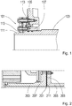
- Ausführungsbeispiele der Erfindung sind in den Figuren dargestellt. Übereinstimmende Bezugsziffern kennzeichnen dabei gleiche oder funktionsgleiche Merkmale. Im Einzelnen zeigt:
- Fig. 1
- ein Fixiermittel mit Einlage; und
- Fig. 2
- eine Kupplung.
- Das in
Fig. 1 dargestellte Fixiermittel 101 dient dazu, ein Durchführungsrohr 103 antriebsseitig in einem Planetenträger 105 zu fixieren. Durch das Fixiermittel 101 wird insbesondere die radiale Position des Durchführungsrohrs 103 festgelegt. Das Fixiermittel 101 selbst ist starr in dem Planetenträger 105 fixiert, das heißt eine Fixierung zwischen dem Fixiermittel 101 und dem Planetenträger 105 lässt keinerlei Relativbewegungen zwischen dem Fixiermittel 101 und dem Planetenträger 105 zu. - Ein metallischer Grundkörper 107 des Fixiermittels 101 ist im Querschnitt L-förmig aufgebaut. Der Grundkörper 107 ist mit dem Planetenträger 105 verschraubt. Entsprechende Verschraubungen sind elektrisch isolierend ausgeführt.
- Eine mit dem Grundkörper 107 verschraubte Nase 109 greift in eine Aussparung 109 des Durchführungsrohrs 103 ein, um das Durchführungsrohr 103 relativ zu dem Planetenträger 105 drehfest zu fixieren.
- In einen zwischen dem Grundkörper 107 und dem Planetenträger 105 verlaufenden Spalt ist eine Isolierschicht 113 eingebracht. Diese besteht aus einem elektrischen Isolator, etwa Polyamid. Die Isolierschicht 113 isoliert den Grundkörper 107 und damit das Durchführungsrohr 103 elektrisch gegenüber dem Planetenträger 105. Wie der Querschnitt des Grundkörpers 107 ist auch der Querschnitt der Isolierschicht 113 L-förmig.
- Der axiale Schenkel des im Querschnitt L-förmigen Grundkörpers 107 verläuft in axialer Richtung zwischen der Isolierschicht 113 und dem Durchführungsrohr 103. Auf diese Weise wird verhindert, dass sich Maßänderungen der Isolierschicht 113 infolge von Temperaturschwankungen auf das Durchführungsrohr 103 auswirken. So bleibt die axiale Verschiebbarkeit des Durchführungsrohrs 103 gegenüber dem Planetenträger 105 auch bei Temperaturschwankungen erhalten.
- Die in
Fig. 2 dargestellte Kupplung 201 verbindet eine ausgangsseitige Sonnenwelle 203 mit einer Eingangswelle 205 eines Generators. Die Sonnenwelle 203 bildet einen ersten Flansch 207 aus, die Eingangswelle 205 des Generators einen zweiten Flansch 209. Der erste Flansch 207 und der zweite Flansch 209 sind miteinander verschraubt. Auf diese Weise kommt eine drehfeste Verbindung zwischen dem ersten Flansch 207 und dem zweiten Flansch 209 zustande. - Zwischen dem ersten Flansch 207 und dem zweiten Flansch 209 befindet sich eine Scheibe 211, die aus einem elektrischen Isolator besteht. Auch die Verschraubungen des ersten Flansches 207 und des zweiten Flansches 209 sind mit elektrischen Isolatoren gekapselt. Somit sind die Sonnenwelle 203 und die Eingangswelle 205 des Generators elektrisch voneinander isoliert. In Kombination mit dem isolierten Durchführungsrohr wird eine vollständige Isolierung des Getriebes gegenüber dem Generator erreicht.
- Von Vorteil ist eine derartige Kombination insbesondere, weil sie sich die Isolierungen vollständig im Bauraum des Getriebes anordnen lassen. Die Schnittstellen des Getriebes nach außen hin werden daher nicht beeinflusst.
-
- 101
- Fixiermittel
- 103
- Durchführungsrohr
- 105
- Planetenträger
- 107
- Grundkörper
- 111
- Aussparung
- 113
- Isolierschicht
- 201
- Kupplung
- 203
- Sonnenwelle
- 205
- Eingangswelle
- 207
- erster Flansch
- 209
- zweiter Flansch
- 211
- Scheibe
Claims (10)
- Anordnung mit einem Getriebe, einem Durchführungsrohr (103) und einem Fixiermittel (101); wobei
das Durchführungsrohr (103) mittels des Fixiermittels (101) in dem Getriebe fixiert ist; dadurch gekennzeichnet, dass
das Fixiermittel (101) gegenüber dem Durchführungsrohr (103) elektrisch isolierend ausgeführt ist. - Anordnung nach Anspruch 1; dadurch gekennzeichnet, dass das Durchführungsrohr (103) relativ zu dem Fixiermittel (101) axial beweglich ist.
- Anordnung nach einem der vorhergehenden Ansprüche; dadurch gekennzeichnet, das
das Durchführungsrohr (103) mittels des Fixiermittels (101) in einer Welle oder einem drehbar gelagerten Planetenträger (105) des Getriebes fixiert ist; wobei das Fixiermittel (101) das Durchführungsrohr (103) elektrisch gegenüber der Welle oder dem Planetenträger (105) isoliert. - Anordnung nach einem der vorhergehenden Ansprüche; dadurch gekennzeichnet, dass
das Fixiermittel (101) ein zentrisches, durchgehendes Loch aufweist; wobei das Fixiermittel (101) in dem Loch mit dem Durchführungsrohr (103) gefügt ist. - Anordnung nach dem vorhergehenden Anspruch unter Rückbezug auf Anspruch 2; dadurch gekennzeichnet, dass
das Fixiermittel (101) entlang seines radial äußeren Randes mit der Welle oder dem Planetenträger (105) gefügt ist. - Anordnung nach einem der Ansprüche 3 bis 5; dadurch gekennzeichnet, dass das Fixiermittel (101) einen Grundkörper (107) und einen elektrischen Nichtleiter (113) aufweist; wobei
der Nichtleiter (113) zwischen dem Grundkörper (107) und der Welle oder dem Planetenträger (105) angeordnet ist. - Anordnung nach dem vorhergehenden Anspruch; dadurch gekennzeichnet, dass mindestens ein Teil des Grundkörpers (107) radial zwischen dem Durchführungsrohr (103) und dem Nichtleiter (113) angeordnet ist.
- Anordnung nach einem der vorhergehenden Ansprüche; gekennzeichnet durch einen drehwirksam mit dem Getriebe verbundenen Generator.
- Anordnung nach dem vorhergehenden Anspruch; gekennzeichnet durch eine Kupplung (201), die eine Ausgangswelle (203) des Getriebes drehfest mit einer Eingangswelle (205) des Generators verbindet; wobei
die Kupplung (201) elektrisch isolierend ausgeführt ist. - Anordnung mit einem Getriebe, einem Durchführungsrohr und einem Fixiermittel; wobei
das Durchführungsrohr mittels des Fixiermittels in dem Getriebe fixiert ist; dadurch gekennzeichnet, dass
das Durchführungsrohr aus einem Isolator besteht.
Priority Applications (6)
| Application Number | Priority Date | Filing Date | Title |
|---|---|---|---|
| EP19198725.4A EP3795862B2 (de) | 2019-09-20 | 2019-09-20 | Elektrisch isoliertes durchführungsrohr |
| FIEP19198725.4T FI3795862T4 (fi) | 2019-09-20 | 2019-09-20 | Sähköisesti eristetty läpivientiputki |
| ES19198725T ES2905143T5 (en) | 2019-09-20 | 2019-09-20 | Insulated feed-through pipe |
| CN202080052312.0A CN114127447B (zh) | 2019-09-20 | 2020-08-17 | 绝缘的穿通管 |
| US17/642,713 US12276255B2 (en) | 2019-09-20 | 2020-08-17 | Insulated pitch tube |
| PCT/EP2020/072957 WO2021052693A1 (de) | 2019-09-20 | 2020-08-17 | Isoliertes durchführungsrohr |
Applications Claiming Priority (1)
| Application Number | Priority Date | Filing Date | Title |
|---|---|---|---|
| EP19198725.4A EP3795862B2 (de) | 2019-09-20 | 2019-09-20 | Elektrisch isoliertes durchführungsrohr |
Publications (3)
| Publication Number | Publication Date |
|---|---|
| EP3795862A1 true EP3795862A1 (de) | 2021-03-24 |
| EP3795862B1 EP3795862B1 (de) | 2021-12-08 |
| EP3795862B2 EP3795862B2 (de) | 2024-12-18 |
Family
ID=67998379
Family Applications (1)
| Application Number | Title | Priority Date | Filing Date |
|---|---|---|---|
| EP19198725.4A Active EP3795862B2 (de) | 2019-09-20 | 2019-09-20 | Elektrisch isoliertes durchführungsrohr |
Country Status (6)
| Country | Link |
|---|---|
| US (1) | US12276255B2 (de) |
| EP (1) | EP3795862B2 (de) |
| CN (1) | CN114127447B (de) |
| ES (1) | ES2905143T5 (de) |
| FI (1) | FI3795862T4 (de) |
| WO (1) | WO2021052693A1 (de) |
Cited By (2)
| Publication number | Priority date | Publication date | Assignee | Title |
|---|---|---|---|---|
| EP4345300A1 (de) | 2022-09-28 | 2024-04-03 | Flender GmbH | Betriebssicheres pitchrohr für eine blatteinstellwinkelregelung einer windkraftanlage |
| EP4345299A1 (de) | 2022-09-27 | 2024-04-03 | Flender GmbH | Betriebssichere lageranordnung für ein pitchrohr einer windkraftanlage |
Families Citing this family (1)
| Publication number | Priority date | Publication date | Assignee | Title |
|---|---|---|---|---|
| CN116906274B (zh) * | 2022-06-29 | 2023-12-19 | 北京金风科创风电设备有限公司 | 传动系统及风力发电机组 |
Citations (5)
| Publication number | Priority date | Publication date | Assignee | Title |
|---|---|---|---|---|
| US6019292A (en) * | 1995-06-29 | 2000-02-01 | Itt Manufacturing Enterprises, Inc. | Sealing part used in a metallic tubelet for windshield cleaning systems |
| EP2541058A1 (de) * | 2011-06-30 | 2013-01-02 | Siemens Aktiengesellschaft | Antriebssystem für eine Windkraftanlage |
| DE102014200674A1 (de) * | 2014-01-16 | 2015-07-16 | Zf Friedrichshafen Ag | Anschlussstück für ein Pitchrohr |
| EP3001062A1 (de) * | 2014-09-26 | 2016-03-30 | Siemens Aktiengesellschaft | Überlastkupplung |
| US20170023067A1 (en) * | 2014-03-12 | 2017-01-26 | Siemens Aktiengesellschaft | Gear coupling |
Family Cites Families (17)
| Publication number | Priority date | Publication date | Assignee | Title |
|---|---|---|---|---|
| JPS5912899B2 (ja) * | 1977-11-05 | 1984-03-26 | 松下電器産業株式会社 | 機器の歯車装置 |
| DK2080904T3 (da) | 2008-01-17 | 2011-06-27 | Hansen Transmissions Int | Et gear til en vindturbine |
| US8376708B2 (en) | 2009-06-30 | 2013-02-19 | General Electric Company | Drivetrain system for a wind turbine generator and method of assembling the same |
| KR101775373B1 (ko) * | 2010-06-21 | 2017-09-06 | 엔비전 에너지 (덴마크) 에이피에스 | 가요성 샤프트 풍력 터빈 |
| DE102010053389A1 (de) * | 2010-12-03 | 2012-06-06 | Vishay Electronic Gmbh | Elektrischer Leistungswiderstand |
| ES2545986T3 (es) * | 2011-04-07 | 2015-09-17 | Siemens Aktiengesellschaft | Unidad compacta generador-engranaje para centrales de energía eólica |
| EP2541096A1 (de) * | 2011-06-30 | 2013-01-02 | Siemens Aktiengesellschaft | Antriebssystem für eine Windkraftanlage |
| KR101367115B1 (ko) | 2011-12-05 | 2014-02-26 | 대우조선해양 주식회사 | 풍력발전기의 슬립링 배치구조 및 이를 갖는 풍력 발전기 |
| DE102012002347A1 (de) * | 2011-12-24 | 2013-06-27 | Robert Bosch Gmbh | Elektrische Maschine für eine Windenergieanlage |
| EP2617994B1 (de) | 2012-01-20 | 2021-01-13 | ZF Wind Power Antwerpen NV | Antriebsstrang für eine Windenergieanlage |
| DE102014000044B3 (de) | 2014-01-07 | 2015-05-07 | Senvion Se | Vorrichtung zur Führung eines Leitungsstrangs innerhalb einer Hohlwelle |
| EP2933483A1 (de) | 2014-04-15 | 2015-10-21 | Siemens Aktiengesellschaft | Antriebssystem einer Windkraftanlage |
| US11365722B2 (en) | 2016-12-29 | 2022-06-21 | Vestas Wind Systems A/S | Insulated shaft joint |
| DE102017212537A1 (de) | 2017-07-21 | 2019-01-24 | Zf Friedrichshafen Ag | Hoch belastbare, elektrisch isolierende Kupplung |
| CN207161276U (zh) | 2017-09-11 | 2018-03-30 | 三一重能有限公司 | 风力发电机及其传动轴内置电缆保护装置 |
| DE102017221362A1 (de) * | 2017-11-29 | 2019-05-29 | Zf Friedrichshafen Ag | Fixierung eines Pitchrohrs |
| ES2902893T5 (en) * | 2019-09-20 | 2025-01-28 | Zahnradfabrik Friedrichshafen | Gear box arrangement for wind turbine with insulated feed-through pipe |
-
2019
- 2019-09-20 FI FIEP19198725.4T patent/FI3795862T4/fi active
- 2019-09-20 EP EP19198725.4A patent/EP3795862B2/de active Active
- 2019-09-20 ES ES19198725T patent/ES2905143T5/es active Active
-
2020
- 2020-08-17 CN CN202080052312.0A patent/CN114127447B/zh active Active
- 2020-08-17 WO PCT/EP2020/072957 patent/WO2021052693A1/de not_active Ceased
- 2020-08-17 US US17/642,713 patent/US12276255B2/en active Active
Patent Citations (5)
| Publication number | Priority date | Publication date | Assignee | Title |
|---|---|---|---|---|
| US6019292A (en) * | 1995-06-29 | 2000-02-01 | Itt Manufacturing Enterprises, Inc. | Sealing part used in a metallic tubelet for windshield cleaning systems |
| EP2541058A1 (de) * | 2011-06-30 | 2013-01-02 | Siemens Aktiengesellschaft | Antriebssystem für eine Windkraftanlage |
| DE102014200674A1 (de) * | 2014-01-16 | 2015-07-16 | Zf Friedrichshafen Ag | Anschlussstück für ein Pitchrohr |
| US20170023067A1 (en) * | 2014-03-12 | 2017-01-26 | Siemens Aktiengesellschaft | Gear coupling |
| EP3001062A1 (de) * | 2014-09-26 | 2016-03-30 | Siemens Aktiengesellschaft | Überlastkupplung |
Cited By (8)
| Publication number | Priority date | Publication date | Assignee | Title |
|---|---|---|---|---|
| EP4345299A1 (de) | 2022-09-27 | 2024-04-03 | Flender GmbH | Betriebssichere lageranordnung für ein pitchrohr einer windkraftanlage |
| WO2024068186A1 (de) | 2022-09-27 | 2024-04-04 | Flender Gmbh | Betriebssichere lageranordnung für ein pitchrohr einer windkraftanlage |
| CN119895145A (zh) * | 2022-09-27 | 2025-04-25 | 弗兰德有限公司 | 用于风力涡轮机的变桨管的操作可靠的轴承组件 |
| US12467436B2 (en) | 2022-09-27 | 2025-11-11 | Flender Gmbh | Operationally reliable bearing assembly for a pitch tube of a wind turbine |
| EP4345300A1 (de) | 2022-09-28 | 2024-04-03 | Flender GmbH | Betriebssicheres pitchrohr für eine blatteinstellwinkelregelung einer windkraftanlage |
| WO2024068191A1 (de) | 2022-09-28 | 2024-04-04 | Flender Gmbh | Betriebssicheres pitchrohr für eine blatteinstellwinkelregelung einer windkraftanlage |
| CN119998545A (zh) * | 2022-09-28 | 2025-05-13 | 弗兰德有限公司 | 用于风力涡轮机的叶片变桨控制系统的可靠变桨管 |
| US12553418B2 (en) | 2022-09-28 | 2026-02-17 | Flender Gmbh | Reliable pitch tube for a blade pitch control system of a wind turbine |
Also Published As
| Publication number | Publication date |
|---|---|
| FI3795862T4 (fi) | 2025-03-21 |
| EP3795862B2 (de) | 2024-12-18 |
| US20220341398A1 (en) | 2022-10-27 |
| ES2905143T5 (en) | 2025-04-11 |
| EP3795862B1 (de) | 2021-12-08 |
| WO2021052693A1 (de) | 2021-03-25 |
| CN114127447A (zh) | 2022-03-01 |
| US12276255B2 (en) | 2025-04-15 |
| ES2905143T3 (es) | 2022-04-07 |
| CN114127447B (zh) | 2025-06-10 |
Similar Documents
| Publication | Publication Date | Title |
|---|---|---|
| EP3795862B1 (de) | Elektrisch isoliertes durchführungsrohr | |
| EP3795825B1 (de) | Elektrisch isoliertes durchführungsrohr | |
| DE102015006084B4 (de) | Antriebsanordnung mit einem Überlagerungsgetriebe und einer mit variabel einstellbarer Drehzahl anzutreibenden Arbeitsmaschine | |
| EP3982520A1 (de) | Anordnung zur abdichtung und erdung einer welle für ein getriebe, für eine elektrische maschine, oder für eine elektrische achsantriebs-einheit | |
| DE102015211644B4 (de) | Verbesserte elektromagnetische Verträglichkeit einer Antriebsordnung für ein elektrisch angetriebenes Fahrzeug | |
| DE102007060985A1 (de) | Vorrichtung zur Übertragung von Bereitstellungsmitteln | |
| DE102015223669B4 (de) | Planetengetriebe für eine Windkraftanlage und Verfahren zur Montage des Planetengetriebes | |
| EP3795861A1 (de) | Lagerung eines durchführungsrohrs | |
| WO2021004698A1 (de) | Übertragung von energie und daten mittels eines öldurchführungsrings | |
| DE102015225606B4 (de) | Generator mit Getriebestufe | |
| DE112018007566T5 (de) | Elektrisches Brückenantriebssystem und Fahrzeug | |
| DE102021131340B3 (de) | Triebwellenanordnung mit einem innenverzahnten Träger; Getriebe und Antriebseinheit | |
| WO2022234079A1 (de) | Wellenerdungseinrichtung zur herstellung einer elektrisch leitfähigen verbindung zwischen einer drehbaren welle und einem gehäuse | |
| DE102018206107A1 (de) | Erdung eines Generators | |
| WO2024068191A1 (de) | Betriebssicheres pitchrohr für eine blatteinstellwinkelregelung einer windkraftanlage | |
| DE102021125229A1 (de) | Elektrisch betreibbarer Achsantriebsstrang und Planetengetriebe | |
| DE102005059528B4 (de) | Kraftübertragungssystem für ein Hybridfahrzeug | |
| DE102010010201A1 (de) | Windkraftanlage mit Getriebe/Generator-Baueinheit | |
| DE102021201875B4 (de) | Getriebe bzw. Verfahren zum Betrieb eines Getriebes | |
| EP4594636B1 (de) | Betriebssichere lageranordnung für ein pitchrohr einer windkraftanlage | |
| DE102020204639A1 (de) | Getriebe für ein elektrisches Antriebssystem eines Kraftfahrzeugs sowie elektrisches Antriebssystem mit einem solchen Getriebe | |
| DE102015012721A1 (de) | Antriebs- und/oder Getriebeeinrichtung für ein Kraftfahrzeug sowie entsprechendes Kraftfahrzeug | |
| DE102017223353A1 (de) | Hochbelastbare drehfeste Verbindung | |
| DE102016202735A1 (de) | Teilbares Pitchrohr | |
| EP2918471A1 (de) | Einzelachsantrieb eines Schienenfahrzeugs |
Legal Events
| Date | Code | Title | Description |
|---|---|---|---|
| PUAI | Public reference made under article 153(3) epc to a published international application that has entered the european phase |
Free format text: ORIGINAL CODE: 0009012 |
|
| STAA | Information on the status of an ep patent application or granted ep patent |
Free format text: STATUS: REQUEST FOR EXAMINATION WAS MADE |
|
| 17P | Request for examination filed |
Effective date: 20200727 |
|
| AK | Designated contracting states |
Kind code of ref document: A1 Designated state(s): AL AT BE BG CH CY CZ DE DK EE ES FI FR GB GR HR HU IE IS IT LI LT LU LV MC MK MT NL NO PL PT RO RS SE SI SK SM TR |
|
| AX | Request for extension of the european patent |
Extension state: BA ME |
|
| GRAP | Despatch of communication of intention to grant a patent |
Free format text: ORIGINAL CODE: EPIDOSNIGR1 |
|
| STAA | Information on the status of an ep patent application or granted ep patent |
Free format text: STATUS: GRANT OF PATENT IS INTENDED |
|
| INTG | Intention to grant announced |
Effective date: 20210716 |
|
| GRAS | Grant fee paid |
Free format text: ORIGINAL CODE: EPIDOSNIGR3 |
|
| GRAA | (expected) grant |
Free format text: ORIGINAL CODE: 0009210 |
|
| STAA | Information on the status of an ep patent application or granted ep patent |
Free format text: STATUS: THE PATENT HAS BEEN GRANTED |
|
| AK | Designated contracting states |
Kind code of ref document: B1 Designated state(s): AL AT BE BG CH CY CZ DE DK EE ES FI FR GB GR HR HU IE IS IT LI LT LU LV MC MK MT NL NO PL PT RO RS SE SI SK SM TR |
|
| REG | Reference to a national code |
Ref country code: GB Ref legal event code: FG4D Free format text: NOT ENGLISH |
|
| REG | Reference to a national code |
Ref country code: AT Ref legal event code: REF Ref document number: 1454017 Country of ref document: AT Kind code of ref document: T Effective date: 20211215 Ref country code: CH Ref legal event code: EP |
|
| REG | Reference to a national code |
Ref country code: DE Ref legal event code: R096 Ref document number: 502019002952 Country of ref document: DE |
|
| REG | Reference to a national code |
Ref country code: IE Ref legal event code: FG4D Free format text: LANGUAGE OF EP DOCUMENT: GERMAN |
|
| REG | Reference to a national code |
Ref country code: FI Ref legal event code: FGE |
|
| REG | Reference to a national code |
Ref country code: ES Ref legal event code: FG2A Ref document number: 2905143 Country of ref document: ES Kind code of ref document: T3 Effective date: 20220407 |
|
| REG | Reference to a national code |
Ref country code: LT Ref legal event code: MG9D |
|
| REG | Reference to a national code |
Ref country code: NL Ref legal event code: MP Effective date: 20211208 |
|
| PG25 | Lapsed in a contracting state [announced via postgrant information from national office to epo] |
Ref country code: RS Free format text: LAPSE BECAUSE OF FAILURE TO SUBMIT A TRANSLATION OF THE DESCRIPTION OR TO PAY THE FEE WITHIN THE PRESCRIBED TIME-LIMIT Effective date: 20211208 Ref country code: LT Free format text: LAPSE BECAUSE OF FAILURE TO SUBMIT A TRANSLATION OF THE DESCRIPTION OR TO PAY THE FEE WITHIN THE PRESCRIBED TIME-LIMIT Effective date: 20211208 Ref country code: BG Free format text: LAPSE BECAUSE OF FAILURE TO SUBMIT A TRANSLATION OF THE DESCRIPTION OR TO PAY THE FEE WITHIN THE PRESCRIBED TIME-LIMIT Effective date: 20220308 |
|
| PG25 | Lapsed in a contracting state [announced via postgrant information from national office to epo] |
Ref country code: SE Free format text: LAPSE BECAUSE OF FAILURE TO SUBMIT A TRANSLATION OF THE DESCRIPTION OR TO PAY THE FEE WITHIN THE PRESCRIBED TIME-LIMIT Effective date: 20211208 Ref country code: NO Free format text: LAPSE BECAUSE OF FAILURE TO SUBMIT A TRANSLATION OF THE DESCRIPTION OR TO PAY THE FEE WITHIN THE PRESCRIBED TIME-LIMIT Effective date: 20220308 Ref country code: LV Free format text: LAPSE BECAUSE OF FAILURE TO SUBMIT A TRANSLATION OF THE DESCRIPTION OR TO PAY THE FEE WITHIN THE PRESCRIBED TIME-LIMIT Effective date: 20211208 Ref country code: HR Free format text: LAPSE BECAUSE OF FAILURE TO SUBMIT A TRANSLATION OF THE DESCRIPTION OR TO PAY THE FEE WITHIN THE PRESCRIBED TIME-LIMIT Effective date: 20211208 Ref country code: GR Free format text: LAPSE BECAUSE OF FAILURE TO SUBMIT A TRANSLATION OF THE DESCRIPTION OR TO PAY THE FEE WITHIN THE PRESCRIBED TIME-LIMIT Effective date: 20220309 |
|
| PG25 | Lapsed in a contracting state [announced via postgrant information from national office to epo] |
Ref country code: NL Free format text: LAPSE BECAUSE OF FAILURE TO SUBMIT A TRANSLATION OF THE DESCRIPTION OR TO PAY THE FEE WITHIN THE PRESCRIBED TIME-LIMIT Effective date: 20211208 |
|
| PG25 | Lapsed in a contracting state [announced via postgrant information from national office to epo] |
Ref country code: SM Free format text: LAPSE BECAUSE OF FAILURE TO SUBMIT A TRANSLATION OF THE DESCRIPTION OR TO PAY THE FEE WITHIN THE PRESCRIBED TIME-LIMIT Effective date: 20211208 Ref country code: SK Free format text: LAPSE BECAUSE OF FAILURE TO SUBMIT A TRANSLATION OF THE DESCRIPTION OR TO PAY THE FEE WITHIN THE PRESCRIBED TIME-LIMIT Effective date: 20211208 Ref country code: RO Free format text: LAPSE BECAUSE OF FAILURE TO SUBMIT A TRANSLATION OF THE DESCRIPTION OR TO PAY THE FEE WITHIN THE PRESCRIBED TIME-LIMIT Effective date: 20211208 Ref country code: PT Free format text: LAPSE BECAUSE OF FAILURE TO SUBMIT A TRANSLATION OF THE DESCRIPTION OR TO PAY THE FEE WITHIN THE PRESCRIBED TIME-LIMIT Effective date: 20220408 Ref country code: EE Free format text: LAPSE BECAUSE OF FAILURE TO SUBMIT A TRANSLATION OF THE DESCRIPTION OR TO PAY THE FEE WITHIN THE PRESCRIBED TIME-LIMIT Effective date: 20211208 Ref country code: CZ Free format text: LAPSE BECAUSE OF FAILURE TO SUBMIT A TRANSLATION OF THE DESCRIPTION OR TO PAY THE FEE WITHIN THE PRESCRIBED TIME-LIMIT Effective date: 20211208 |
|
| PG25 | Lapsed in a contracting state [announced via postgrant information from national office to epo] |
Ref country code: PL Free format text: LAPSE BECAUSE OF FAILURE TO SUBMIT A TRANSLATION OF THE DESCRIPTION OR TO PAY THE FEE WITHIN THE PRESCRIBED TIME-LIMIT Effective date: 20211208 |
|
| REG | Reference to a national code |
Ref country code: DE Ref legal event code: R026 Ref document number: 502019002952 Country of ref document: DE |
|
| PLBI | Opposition filed |
Free format text: ORIGINAL CODE: 0009260 |
|
| PLAX | Notice of opposition and request to file observation + time limit sent |
Free format text: ORIGINAL CODE: EPIDOSNOBS2 |
|
| PG25 | Lapsed in a contracting state [announced via postgrant information from national office to epo] |
Ref country code: IS Free format text: LAPSE BECAUSE OF FAILURE TO SUBMIT A TRANSLATION OF THE DESCRIPTION OR TO PAY THE FEE WITHIN THE PRESCRIBED TIME-LIMIT Effective date: 20220408 |
|
| REG | Reference to a national code |
Ref country code: FI Ref legal event code: MDE Opponent name: SIEMENS GAMESA RENEWABLE ENERGY GMBH & CO. KG |
|
| 26 | Opposition filed |
Opponent name: SIEMENS GAMESA RENEWABLE ENERGY GMBH & CO. KG Effective date: 20220906 |
|
| PG25 | Lapsed in a contracting state [announced via postgrant information from national office to epo] |
Ref country code: DK Free format text: LAPSE BECAUSE OF FAILURE TO SUBMIT A TRANSLATION OF THE DESCRIPTION OR TO PAY THE FEE WITHIN THE PRESCRIBED TIME-LIMIT Effective date: 20211208 Ref country code: AL Free format text: LAPSE BECAUSE OF FAILURE TO SUBMIT A TRANSLATION OF THE DESCRIPTION OR TO PAY THE FEE WITHIN THE PRESCRIBED TIME-LIMIT Effective date: 20211208 |
|
| PLBB | Reply of patent proprietor to notice(s) of opposition received |
Free format text: ORIGINAL CODE: EPIDOSNOBS3 |
|
| PG25 | Lapsed in a contracting state [announced via postgrant information from national office to epo] |
Ref country code: MC Free format text: LAPSE BECAUSE OF FAILURE TO SUBMIT A TRANSLATION OF THE DESCRIPTION OR TO PAY THE FEE WITHIN THE PRESCRIBED TIME-LIMIT Effective date: 20211208 |
|
| REG | Reference to a national code |
Ref country code: CH Ref legal event code: PL |
|
| REG | Reference to a national code |
Ref country code: BE Ref legal event code: MM Effective date: 20220930 |
|
| PG25 | Lapsed in a contracting state [announced via postgrant information from national office to epo] |
Ref country code: IT Free format text: LAPSE BECAUSE OF FAILURE TO SUBMIT A TRANSLATION OF THE DESCRIPTION OR TO PAY THE FEE WITHIN THE PRESCRIBED TIME-LIMIT Effective date: 20211208 |
|
| PG25 | Lapsed in a contracting state [announced via postgrant information from national office to epo] |
Ref country code: LU Free format text: LAPSE BECAUSE OF NON-PAYMENT OF DUE FEES Effective date: 20220920 |
|
| PG25 | Lapsed in a contracting state [announced via postgrant information from national office to epo] |
Ref country code: LI Free format text: LAPSE BECAUSE OF NON-PAYMENT OF DUE FEES Effective date: 20220930 Ref country code: IE Free format text: LAPSE BECAUSE OF NON-PAYMENT OF DUE FEES Effective date: 20220920 Ref country code: FR Free format text: LAPSE BECAUSE OF NON-PAYMENT OF DUE FEES Effective date: 20220930 Ref country code: CH Free format text: LAPSE BECAUSE OF NON-PAYMENT OF DUE FEES Effective date: 20220930 |
|
| PG25 | Lapsed in a contracting state [announced via postgrant information from national office to epo] |
Ref country code: BE Free format text: LAPSE BECAUSE OF NON-PAYMENT OF DUE FEES Effective date: 20220930 |
|
| PG25 | Lapsed in a contracting state [announced via postgrant information from national office to epo] |
Ref country code: CY Free format text: LAPSE BECAUSE OF FAILURE TO SUBMIT A TRANSLATION OF THE DESCRIPTION OR TO PAY THE FEE WITHIN THE PRESCRIBED TIME-LIMIT Effective date: 20211208 |
|
| GBPC | Gb: european patent ceased through non-payment of renewal fee |
Effective date: 20230920 |
|
| PG25 | Lapsed in a contracting state [announced via postgrant information from national office to epo] |
Ref country code: MK Free format text: LAPSE BECAUSE OF FAILURE TO SUBMIT A TRANSLATION OF THE DESCRIPTION OR TO PAY THE FEE WITHIN THE PRESCRIBED TIME-LIMIT Effective date: 20211208 Ref country code: HU Free format text: LAPSE BECAUSE OF FAILURE TO SUBMIT A TRANSLATION OF THE DESCRIPTION OR TO PAY THE FEE WITHIN THE PRESCRIBED TIME-LIMIT; INVALID AB INITIO Effective date: 20190920 |
|
| PG25 | Lapsed in a contracting state [announced via postgrant information from national office to epo] |
Ref country code: TR Free format text: LAPSE BECAUSE OF FAILURE TO SUBMIT A TRANSLATION OF THE DESCRIPTION OR TO PAY THE FEE WITHIN THE PRESCRIBED TIME-LIMIT Effective date: 20211208 |
|
| PG25 | Lapsed in a contracting state [announced via postgrant information from national office to epo] |
Ref country code: GB Free format text: LAPSE BECAUSE OF NON-PAYMENT OF DUE FEES Effective date: 20230920 |
|
| PG25 | Lapsed in a contracting state [announced via postgrant information from national office to epo] |
Ref country code: GB Free format text: LAPSE BECAUSE OF NON-PAYMENT OF DUE FEES Effective date: 20230920 |
|
| PG25 | Lapsed in a contracting state [announced via postgrant information from national office to epo] |
Ref country code: MT Free format text: LAPSE BECAUSE OF FAILURE TO SUBMIT A TRANSLATION OF THE DESCRIPTION OR TO PAY THE FEE WITHIN THE PRESCRIBED TIME-LIMIT Effective date: 20211208 |
|
| PGFP | Annual fee paid to national office [announced via postgrant information from national office to epo] |
Ref country code: FI Payment date: 20240912 Year of fee payment: 6 |
|
| PUAH | Patent maintained in amended form |
Free format text: ORIGINAL CODE: 0009272 |
|
| STAA | Information on the status of an ep patent application or granted ep patent |
Free format text: STATUS: PATENT MAINTAINED AS AMENDED |
|
| 27A | Patent maintained in amended form |
Effective date: 20241218 |
|
| AK | Designated contracting states |
Kind code of ref document: B2 Designated state(s): AL AT BE BG CH CY CZ DE DK EE ES FI FR GB GR HR HU IE IS IT LI LT LU LV MC MK MT NL NO PL PT RO RS SE SI SK SM TR |
|
| REG | Reference to a national code |
Ref country code: DE Ref legal event code: R102 Ref document number: 502019002952 Country of ref document: DE |
|
| REG | Reference to a national code |
Ref country code: ES Ref legal event code: DC2A Ref document number: 2905143 Country of ref document: ES Kind code of ref document: T5 Effective date: 20250411 |
|
| PGFP | Annual fee paid to national office [announced via postgrant information from national office to epo] |
Ref country code: DE Payment date: 20250919 Year of fee payment: 7 |
|
| REG | Reference to a national code |
Ref country code: AT Ref legal event code: MM01 Ref document number: 1454017 Country of ref document: AT Kind code of ref document: T Effective date: 20240920 |
|
| PG25 | Lapsed in a contracting state [announced via postgrant information from national office to epo] |
Ref country code: AT Free format text: LAPSE BECAUSE OF NON-PAYMENT OF DUE FEES Effective date: 20240920 |
|
| PGFP | Annual fee paid to national office [announced via postgrant information from national office to epo] |
Ref country code: ES Payment date: 20251020 Year of fee payment: 7 |
|
| PG25 | Lapsed in a contracting state [announced via postgrant information from national office to epo] |
Ref country code: SI Free format text: LAPSE BECAUSE OF FAILURE TO SUBMIT A TRANSLATION OF THE DESCRIPTION OR TO PAY THE FEE WITHIN THE PRESCRIBED TIME-LIMIT Effective date: 20211208 |
|
| PG25 | Lapsed in a contracting state [announced via postgrant information from national office to epo] |
Ref country code: FI Free format text: LAPSE BECAUSE OF NON-PAYMENT OF DUE FEES Effective date: 20250920 |
|
| PGFP | Annual fee paid to national office [announced via postgrant information from national office to epo] |
Ref country code: AT Payment date: 20260410 Year of fee payment: 5 |